EP2538464A2 - Thermoelectric conversion units - Google Patents
Thermoelectric conversion units Download PDFInfo
- Publication number
- EP2538464A2 EP2538464A2 EP12171256A EP12171256A EP2538464A2 EP 2538464 A2 EP2538464 A2 EP 2538464A2 EP 12171256 A EP12171256 A EP 12171256A EP 12171256 A EP12171256 A EP 12171256A EP 2538464 A2 EP2538464 A2 EP 2538464A2
- Authority
- EP
- European Patent Office
- Prior art keywords
- case
- frame member
- thermoelectric conversion
- substrates
- flow channel
- Prior art date
- Legal status (The legal status is an assumption and is not a legal conclusion. Google has not performed a legal analysis and makes no representation as to the accuracy of the status listed.)
- Withdrawn
Links
- 238000006243 chemical reaction Methods 0.000 title claims abstract description 82
- 239000000758 substrate Substances 0.000 claims abstract description 70
- 230000002093 peripheral effect Effects 0.000 claims abstract description 67
- 238000007789 sealing Methods 0.000 claims abstract description 17
- 230000000994 depressogenic effect Effects 0.000 claims description 59
- 238000010438 heat treatment Methods 0.000 description 5
- 238000001816 cooling Methods 0.000 description 4
- 239000011347 resin Substances 0.000 description 4
- 229920005989 resin Polymers 0.000 description 4
- 230000005611 electricity Effects 0.000 description 3
- 230000005679 Peltier effect Effects 0.000 description 2
- 239000004020 conductor Substances 0.000 description 2
- 239000002826 coolant Substances 0.000 description 2
- 239000007788 liquid Substances 0.000 description 2
- 238000012986 modification Methods 0.000 description 2
- 230000004048 modification Effects 0.000 description 2
- 238000005192 partition Methods 0.000 description 2
- 230000005678 Seebeck effect Effects 0.000 description 1
- 230000005680 Thomson effect Effects 0.000 description 1
- 238000010276 construction Methods 0.000 description 1
- 230000001419 dependent effect Effects 0.000 description 1
- 238000010586 diagram Methods 0.000 description 1
- 230000000694 effects Effects 0.000 description 1
- 230000005489 elastic deformation Effects 0.000 description 1
- 238000003780 insertion Methods 0.000 description 1
- 230000037431 insertion Effects 0.000 description 1
- 238000004519 manufacturing process Methods 0.000 description 1
- 239000000463 material Substances 0.000 description 1
- 239000002184 metal Substances 0.000 description 1
- 229910052751 metal Inorganic materials 0.000 description 1
- 150000002739 metals Chemical class 0.000 description 1
- 239000004065 semiconductor Substances 0.000 description 1
Images





Classifications
-
- H—ELECTRICITY
- H10—SEMICONDUCTOR DEVICES; ELECTRIC SOLID-STATE DEVICES NOT OTHERWISE PROVIDED FOR
- H10N—ELECTRIC SOLID-STATE DEVICES NOT OTHERWISE PROVIDED FOR
- H10N10/00—Thermoelectric devices comprising a junction of dissimilar materials, i.e. devices exhibiting Seebeck or Peltier effects
- H10N10/10—Thermoelectric devices comprising a junction of dissimilar materials, i.e. devices exhibiting Seebeck or Peltier effects operating with only the Peltier or Seebeck effects
- H10N10/17—Thermoelectric devices comprising a junction of dissimilar materials, i.e. devices exhibiting Seebeck or Peltier effects operating with only the Peltier or Seebeck effects characterised by the structure or configuration of the cell or thermocouple forming the device
Definitions
- Embodiments of the present invention relate to a thermoelectric conversion unit having a thermoelectric conversion element.
- thermoelectric conversion unit described in Japanese Laid-Open Patent Publication 2001-119076 includes a pair of substrates opposing each other, a plurality of thermoelectric conversion elements provided between the pair of substrates, and an insulative resin filled between the plurality of thermoelectric conversion elements between the pair of substrates. The pair of substrates and the thermoelectric conversion elements are integrated by the insulative resin.
- a thermoelectric conversion unit described in Japanese Laid-Open Patent Publication 2001-4245 includes a case formed with a flow channel having an open structure, a thermoelectric conversion module having thermoelectric conversion elements and configured to cover the opening portion of the flow channel, and a seal member configured to seal a portion between the thermoelectric conversion module and the case.
- thermoelectric conversion unit having a simple structure in which the thermoelectric conversion elements can be securely held between the pair of substrates. It is also preferred that the case formed with the flow channel can also be mounted securely.
- thermoelectric conversion unit having a pair of substrates opposing each other, thermoelectric conversion elements provided between the pair of substrates, a frame member, and a case.
- the frame member may be mounted along an outer peripheral portion of the pair of substrates.
- the case may be formed with flow channels having an opened structure. Opening portions of the flow channels may be covered with the substrates.
- the case may include a peripheral wall portion configured to cover the outer peripheral portion of the frame member. The peripheral wall portion of the case and the outer peripheral portion of the frame member are preferably arranged in close proximity such that sealing may occur.
- the frame member may hold the pair of the substrate, and the thermoelectric conversion elements via the pair of the substrates.
- the frame member may be easily configured due to its structure extending along the outer peripheral portions the pair of substrates.
- the case and the frame member preferably tightly contact with each other and hence can be mounted with each other with stability.
- a heat exchange system 10 is provided, for example, on a vehicle, and as shown in FIG. 1 , may include a thermoelectric conversion unit 1, a radiator 11 and an indoor heat exchanger 14.
- the radiator 11 may be connected to an engine 12 of the vehicle by piping 20.
- An outdoor heat medium (coolant liquid) may circulate between the engine 12 and the radiator 11 by a pump 13 provided at a midpoint of the piping 20.
- the outdoor heat medium receives heat from the engine 12 and radiates the heat from the radiator 11 to the outside.
- the thermoelectric conversion unit 1 may be connected to the radiator 11 by piping 21 connected to the piping 20 as shown in FIG. 1 , and may be connected to the radiator 11 in parallel to the engine 12.
- the outdoor heat medium is cooled upon reception of cold from the thermoelectric conversion unit 1 via the piping 20, 21. Therefore, the outdoor heat medium can be cooled not only by the radiator 11 but also by the thermoelectric conversion unit 1.
- the thermoelectric conversion unit 1 may be connected to the indoor heat exchanger 14 by piping 22 as shown in FIG 1 .
- An indoor heat medium (coolant liquid) may circulate between the thermoelectric conversion unit 1 and the indoor heat exchanger 14 by a pump 15 provided at a midpoint of the piping 22.
- the indoor heat medium may receive heat from the thermoelectric conversion unit 1, and radiate the heat to indoor air from the indoor heat exchanger 14. Therefore, the indoor air can be heated by the indoor heat exchanger 14.
- the thermoelectric conversion unit 1 includes a case 3 and preferably a plurality (two, for example) of thermoelectric conversion modules 2 as shown in FIGS. 2 and 3 .
- the case 3 preferably has a cylindrical shape and an internal space formed in the case 3.
- the case 3 preferably includes a top panel 3a, a bottom panel 3b, and side panels 3c and 3d.
- a front panel 3e is preferably provided between front portions of the side panels 3c and 3d
- a rear panel 3f is preferably provided between rear portions of the side panels 3c and 3d
- a center panel 3g is preferably provided between center portions of the side panels 3c and 3d.
- the front panel 3e, the rear panel 3f, and the center panel 3g are preferably positioned between the top panel 3a and the bottom panel 3b. They are preferably positioned so that two flow channels 3h and 3i can be formed between the top panel 3a and the bottom panel 3b.
- Inner side surfaces of the front panel 3e and the rear panel 3f may be formed with depressed portions 3el and 3fl.
- the depressed portions 3el and 3fl may be formed over the entire length of the front panel 3e and the rear panel 3f in the longitudinal direction.
- the center panel 3g preferably has both inner side surfaces opposing the front panel 3e and the rear panel 3f. Depressed portions 3gl may be formed on the both inner side surfaces.
- the depressed portions 3gl may be formed over the entire length of the center panel 3g in the longitudinal direction.
- large depressed portions 3c2 and 3d2 and depressed portions 3c1 and 3d1 are preferably formed on the inner peripheral surfaces of the side panels 3c and 3d.
- the large depressed portions 3c2 and 3d2 are preferably formed at substantially the centers in height of the side panels 3c and 3d, and are formed over the entire length of the side panels 3c and 3d in the longitudinal direction.
- the depressed portions 3c1 and 3dl are preferably formed so as to be depressed on bottom surfaces of the large depressed portions 3c2 and 3d2.
- the depressed portions 3c1 and 3d1 are preferably formed over the entire length of the side panels 3c and 3d in the longitudinal direction.
- the thermoelectric conversion module 2 is preferably inserted into the case 3 in a state in which the side panel 3d is removed.
- the thermoelectric conversion module 2 preferably includes thermoelectric conversion elements 2a, substrates 2b and 2c, and fins 2d and 2e.
- the thermoelectric conversion elements (Peltier elements) 2a are preferably formed of different metals, conductors, or semiconductors.
- the thermoelectric conversion element 2a achieves a Peltier effect by using a DC electricity.
- At least one heating surface absorbs heat as a heat-absorbing portion, while the at least other one radiates heat as a heat-radiating portion.
- a plurality of thermoelectric conversion elements 2a may be provided between the substrates 2b and 2c.
- the plurality of thermoelectric conversion elements 2a are preferably arranged in a plurality of rows in the vertically and laterally planar directions with respect to the substrates 2b and 2c.
- the substrates 2b and 2c are preferably formed into a panel shape as shown in FIG. 4 , and are made from an insulative material.
- the substrates 2b and 2c include inner surfaces 2b2 and 2c2 opposing each other and outer surfaces 2b1 and 2c1 positioned on the back sides of the inner surfaces 2b2 and 2c2.
- the inner surfaces 2b2 and 2c2 are preferably provided with electrodes 2b3 and 2c3 arranged in a plurality of rows in the vertical and lateral directions.
- the electrodes 2b3 and 2c3 are preferably made from a conductive material, and the thermoelectric conversion elements 2a may be soldered on the electrodes 2b3 and 2c3.
- the substrates 2b and 2c may partition an internal space of the case 3 by being inserted into the case 3 as shown in FIGS. 3 and 4 .
- the internal space of the case 3 may be partitioned into the first flow channel 3h by the first substrate 2b and the internal space of the case 3 may be partitioned into the second flow channel 3i by the second substrate 2c.
- the first flow channel 3h and the second flow channel 3i are formed having an opened structure in the interior of the case 3.
- An opening portion of the first flow channel 3h may be covered with the first substrate 2b and an opening portion of the second flow channel 3i may be covered with the second substrate 2c.
- the first flow channel 3h and the second flow channel 3i include inlet ports 3h1 and 3il at one end portion of the case 3 and exits 3h2 and 3i2 at the other end of the case 3.
- the fins 2d and 2e are preferably provided on the outer surfaces 2b1 and 2c1 of the substrates 2b and 2c.
- the fins 2d and 2e project toward the flow channels 3h and 3i from the substrates 2b and 2c.
- the fins 2d and 2e include a plurality of plate portions 2dl and 2el arranged side by side and are formed with gaps 2d2 and 2e2 between the plate portions 2dl and 2el.
- the gaps 2d2 and 2e2 preferably expand in the direction of flow in the flow channels 3h and 3i so as not to block the flow channels 3h and 3i.
- a frame member 4 may be mounted on outer peripheral portions of the substrates 2b and 2c as shown in FIGS. 3 to 5 .
- the frame member 4 is preferably made of a rubber or a resin having a large elastic deformation potential.
- the frame member 4 integrally includes a frame body 4a, a projecting portion 4b, and an inner projecting portion 4c.
- An inner peripheral portion of the frame body 4a preferably has an annular shape and preferably comes into tight contact with the entire outer peripheries of the substrates 2b and 2c. Accordingly, the frame body 4a preferably seals a portion between the outer peripheral portions of the substrates 2b and 2c and protects the thermoelectric conversion elements 2a from the heat medium or the outside air.
- the inner projecting portion 4c may project from the frame body 4a to between the substrates 2b and 2c.
- the inner projecting portion 4c may project from the entire circumference of an inner peripheral surface of the frame body 4a.
- the inner projecting portion 4c is preferably in close proximity to or abuts the inner surfaces 2b2 and 2c2 of the substrates 2b and 2c. Accordingly, the inner projecting portion 4c preferably restricts the substrates 2b and 2c from getting close and the thermoelectric conversion elements 2a from collapsing.
- the projecting portion 4b may project outward from the frame body 4a as shown in FIGS. 3 and 4 .
- the projecting portion 4b preferably projects from the entire periphery of an outer peripheral surface of the frame body 4a.
- the projecting portion 4b may be inserted into the depressed portions 3el to 3gl from the sides of the case 3 from which the side panel 3d is removed.
- the projecting portion 4b may be inserted into the case 3 while being guided to the depressed portions 3el to 3gl.
- the frame member 4 and the thermoelectric conversion module 2 are preferably inserted into the case 3.
- the projecting portion 4b may also be inserted into the depressed portions 3c1 and 3d1 of the side panels 3c and 3d.
- An outer peripheral portion of the frame member 4 preferably opposes a peripheral wall portion 3j (the side panels 3c and 3d, the front panel 3e, the rear panel 3f, and the center panel 3g) of the case 3 and preferably comes into tight contact with the entire periphery with respect to the peripheral wall portion 3j. Accordingly, the frame member 4 may cooperate with the substrates 2b and 2c, and can partition the internal space of the case 3 into the flow channels 3h and 3i.
- the frame member 4 When manufacturing the thermoelectric conversion unit 1, the frame member 4 may be mounted on the thermoelectric conversion module 2 as shown in FIG. 3 .
- the thermoelectric conversion module 2 can be slid and inserted into the case 3 together with the frame member 4.
- the side panel 3d of the case 3 may be mounted on a case body.
- a converter may be electrically connected to the thermoelectric conversion unit 1.
- the converter supplies a DC electricity to the thermoelectric conversion unit 1, and the DC electricity flows in series through the plurality of thermoelectric conversion elements 2a by the electrodes 2b3 and 2c3. With the supply of the electric current, the thermoelectric conversion elements 2a can absorb heat via the second substrate 2c and the second fin 2e and radiate the heat via the first substrate 2b and the first fin 2d .
- the second flow channel 3i of the thermoelectric conversion unit 1 may be connected to the piping 21 as shown in FIG. 1 .
- the outdoor heat medium is supplied to the second flow channel 3i by the pump 13 via the piping 20 and 21,
- the outdoor heat medium is supplied from the inlet port 3i1 to the second flow channel 3i as shown in FIG. 4 .
- the outdoor heat medium preferably flows in the second flow channel 3i, is cooled by from the second substrate 2c and the second fin 2e, and is discharged from the exit 3i2 to the outside of the second flow channel 3i.
- the first flow channel 3h of the thermoelectric conversion unit 1 is preferably connected to the piping 22 as shown in FIG 1 .
- the indoor heat medium is supplied to the first flow channel 3h by the pump 15 via the piping 22.
- the indoor heat medium flows in the first flow channel 3h from the inlet port 3hl as shown in FIG. 4 , thereby receiving heat from the first substrate 2b and the first fin 2d.
- the indoor heat medium is discharged from the exit 3h2 to the outside of the first flow channel 3h, and flows in the indoor heat exchanger 14 shown in FIG 1 .
- the indoor heat exchanger 14 discharges the heat to the air in the interior of the chamber.
- the thermoelectric conversion unit 1 preferably includes the pair of substrates 2b and 2c opposing each other, the thermoelectric conversion elements 2a provided between the pair of substrates 2b and 2c, the frame member 4 and the case 3 as shown in FIGS. 4 and 5 .
- the frame member 4 may be mounted on and along the outer peripheral portion of the pair of substrates 2b and 2c.
- the case 3 is preferably formed with the flow channels 3h and 3i having an opened structure, and whose opening portions of the flow channels 3h and 3i are covered with the substrates 2b and 2c.
- the case 3 includes the peripheral wall portion 3j (3c to 3g) configured to cover the outer peripheral portion of the frame member 4.
- the peripheral wall portion 3j of the case 3 and the outer peripheral portion of the frame member 4 preferably come into tight contact with each other to achieve sealing.
- the frame member 4 preferably holds the pair of the substrates 2b and 2c.
- the pair of substrates 2b and 2c hold the thermoelectric conversion elements 2a.
- the frame member 4 may be easily configured due to its structure extending along the outer peripheral portions of the pair of substrates 2b and 2c. The case 3 and the frame member 4 may be brought into tight contact with each other, and hence be securely mounted with each other.
- the frame member 4 may include an inner peripheral portion contacting the circumferences of the respective outer peripheral portions of the pair of substrates 2b and 2c and/or the outer peripheral portion which contacts the circumference of the peripheral wall portion 3j of the case 3 as shown in FIGS. 4 and 5 . Therefore, the inner peripheral portion of the frame member 4 can protect the thermoelectric conversion elements 2a from the heat medium or the outside air through sealing a portion between the pair of substrates 2b and 2c.
- the frame member 4 is preferably positioned between the case 3 and the substrates 2b and 2c and seals a portion between the case 3 and the substrates 2b and 2c. Therefore, the frame member 4 forms the flow channels 3h and 3i in cooperation with the substrates 2b and 2c.
- the peripheral wall portion 3j of the case 3 may be formed with the depressed portions 3c1 to 3g1.
- the frame member 4 preferably has a projecting portion 4b which can be inserted into the depressed portions 3c1 to 3g1.
- the case 3 and the frame member 4 can be securely mounted using the depressed portions 3c1 to 3gl and the projecting portion 4b.
- the case 3 may be provided with a tubular member formed with opening portions at both ends thereof as shown in FIGS. 3 and 4 .
- the depressed portions 3c1 to 3g1 extending in the axial direction of the tubular member may be formed on the inner peripheral portion of the case 3.
- the depressed portions 3c1 to 3g1 preferably reach both opening portions of the case 3, Therefore, by using the depressed portions 3e1 to 3g1 and the projecting portion 4b, the frame member 4 and the case 3 can be mounted using a sliding movement.
- an internal space configured to store a pair of substrates 2b and 2c and the frame member 4 may be formed in the case 3.
- the internal space includes a first flow channel 3h partitioned by the first substrate 2b and the frame member 4, and a second flow channel 3i partitioned by the second substrate 2c and the frame member 4. Therefore, the frame member 4 forms the two flow channels 3h and 3i in the case 3 through use of the substrates 2b and 2c,
- the thermoelectric conversion unit 1 may have a case 5 as shown in FIGS. 6 and 7 instead of the case 3 shown in FIG. 3 .
- the case 5 may have a cylindrical shape and can be formed with an internal space in the case 5.
- the case 5 may include a top panel 5a, a bottom panel 5b, and side panels 5c and 5d.
- a front panel 5e is preferably provided between front portions of the side panels 5c and 5d, and a rear panel 5f is preferably provided between rear portions of the side panels 5c and 5d.
- the front panel Se and the rear panel 5f may be positioned between the top panel 5a and the bottom panel 5b.
- depressed portions 5c1 and 5dl may be formed on inner side surfaces of the side panels 5c and 5d.
- the depressed portions 5c1 and 5dl are preferably generally positioned at the center of the height of the side panels 5c and 5d, and may be formed over the entire length of the side panels 5c and 5d in the longitudinal direction.
- depressed portions 5el and 5fl may be formed on inner side surfaces of the front panel 5e and the rear panel 5f.
- the depressed portions 5el and 5fl are positioned at substantially the centers of the height of the front panel 5e and the rear panel 5f, and may be formed over the entire length of the front panel 5e and the rear panel 5f in the longitudinal direction.
- thermoelectric conversion module 2 and the frame member 4 may be inserted into the case 5 from the front or rear of the case 5 such that the front panel 5e or the rear panel 5f can be removed.
- the frame member 4 may be inserted into the case 5 while the projecting portion 4b of the frame member 4 is guided into the depressed portions 5c1, and 5dl of the side panels 5c and 5d.
- the two thermoelectric conversion modules 2 are preferably located adjacent to each other in the case 5. Further, the projecting portions 4b of the frame members 4 mounted on the respective thermoelectric conversion modules 2 preferably come into tight contact with each other.
- the front panel 5e and the rear panel 5f may be mounted on the side panels 5c and 5d.
- the projecting portion 4b of the frame member 4 may be inserted into the depressed portion 5el of the front panel 5e and the depressed portion 5f1 of the rear panel 5f.
- the case 5 preferably includes a peripheral portion 5j (5c, 5d, 5e and 5f) configured to cover the outer peripheral portions of the frame members 4.
- the outer peripheral surfaces of the frame members 4 preferably come into tight contact with the peripheral wall portions 5j. Accordingly, the frame members 4 and the thermoelectric conversion modules 2 may form flow channels 5h and 5i in the internal space of the case 5.
- the thermoelectric conversion unit 1 may include a frame member 6 shown in FIGS. 8 and 9 instead of the frame member 4 shown in FIGS. 6 and 7 .
- the frame member 6 may integrally include a frame body 6a, a projecting portion 6b, and an inner projecting portion 6c.
- the frame body 6a may include an annular outer frame portion 6al and a compartmentalizing portion 6a2 compartmentalizing an inner area of the outer frame portion 6al into a plurality of compartments.
- the frame member 6 may be formed with a plurality of opening portions 6a3 by the outer frame portion 6a1 and the compartmentalizing portion 6a2.
- the respective thermoelectric conversion modules 2 may be mounted on the respective opening portions 6a3.
- An inner projecting portion 6c preferably projects between the substrates 2b and 2c from the frame body 6a.
- the inner projecting portions 6c are preferably formed on both surfaces, i.e., the inner peripheral surfaces of the outer same portion 6al and the compartmentalizing portion 6a2.
- the projecting portion 6b may be inserted into the depressed portions 5c1 and 5d1 of the side panels 5c and 5d of the case 5 such that the front panel 5e or the rear panel Sf can be removed by a sliding movement.
- the front panel 5e and the rear panel 5f may be mounted on the front or rear portion of the case 5.
- the projecting portion 6b of the flame member 6 can be inserted into the depressed portions 5el and 5fl of the front panel 5e and the rear panel 5f.
- the frame member 6 preferably comes into tight contact with the circumference of the peripheral wall portion 5j (5c, 5d, 5e and 5f) of the case 5. Accordingly, the frame member 6 preferably forms the flow channels 5h and 5i in the internal space of the case 5 in cooperation with the thermoelectric conversion modules 2.
- the thermoelectric conversion unit 1 may have a case 7 as shown in FIG. 10 instead of the case 3 shown in FIG. 5 .
- the case 7 may include a first case 7a and a second case 7b as shown in FIG. 10 .
- the first case 7a and the second case 7b are preferably stacked in layers and cooperate each other to configure a cylindrical shape.
- the cylindrical shape is similar to the cylindrical shape of the case 3 shown in FIGS. 3 to 5 .
- depressed portions 7al and 7bl which constitute flow channels 7h and 7i having an opened structure, may be formed on the first case 7a and the second case 7b. Opening portions of the flow channels 7h and 7i may be covered with the substrates 2b and 2c.
- the first case 7a may have a peripheral wall portion 7a4 configured to cover an outer periphery of the frame member 4.
- the peripheral wall portion 7a4 can be formed with a large depressed portion 7a3 and a depressed portion 7a2.
- the large depressed portion 7a3 is preferably formed over the entire length of a side wall of the first case 7a.
- the frame member 4 and outer peripheral end portions of the substrates 2b and 2c may be installed in the large depressed portion 7a3.
- the depressed portion 7a2 may be formed so as to be depressed on a bottom surface of the large depressed portion 7a3.
- the depressed portion 7a2 is preferably formed over the entire length of a side wall of the first case 7a.
- the projecting portion 4b of the frame member 4 may be inserted into the depressed portion 7a2.
- the frame member 4 can be mounted in the first case 7a using the projecting portion 4b and the depressed portion 7a2 by a sliding movement.
- the second case 7b may be placed on top of the first case 7a.
- the second case 7b may have an opposed wall portion 7b2 opposing the frame member 4 and a peripheral wall portion 7a4 on an outer periphery of the second flow channel 7i.
- Mounted on the first case 7a may be a front panel and a rear panel formed in the same manner as the front panel 5e and the rear panel 5f shown in FIG 6 .
- the thermoelectric conversion unit 1 may have the case 7 and the frame member 4 shown in FIG. 11 instead of the case 7 and the frame member 4 shown in FIG 10 .
- the case 7 shown in FIG. 11 is not formed with the depressed portion 7a2 shown in FIG 10 , but is formed with depressed portions 7a5 and 7a7 and a projecting portion 7a6.
- the depressed portions 7a5 and 7a7 are formed so as to be depressed on the bottom surface of the large depressed portion 7a3.
- the projecting portion 7a6 projects toward the frame member 4 from the bottom surface of the large depressed portion 7a3.
- the frame member 4 shown in FIG 11 is not formed with the projecting portion 4b shown in FIG. 10 but is preferably formed with projecting portions 4d and 4f and a depressed portion 4e.
- the projecting portions 4d and 4f may be slidably inserted into the depressed portions 7a5 and 7a7 of the case 7.
- the projecting portion 7a6 of the case 7 may be slidably inserted into the depressed portion 4e.
- the frame member 4 can be mounted on the first case 7a using the projecting portions 4d, 4f and 7a6 and the depressed portions 4e, 7a5 and 7a7 via a sliding movement.
- the thermoelectric conversion unit 1 may have the frame member 4 and the case 7 shown in FIG. 12 instead of the frame member 4 and the case 7 shown in FIG. 10 .
- the frame member 4 shown in FIG 12 includes a sealing projecting portion 4g in addition to the configuration shown in FIG. 10 .
- the opposed wall portion 7b2 of the second case 7b is formed with a depressed portion 7b3 in which the sealing projecting portion 4g is inserted.
- the sealing projecting portion 4g may come into resilient contact with the second case 7b by placing the second case 7b on the first case 7a. In such a way, the portion between the frame member 4 and the second case 7b may be sealed.
- the case 7 preferably includes a first case 7a formed with a first flow channel 7h and a second case 7b formed with a second flow channel 7i.
- the first case 7a may have a peripheral wall portion 7a4.
- the second case 7b may have an opposed wall portion 7b2 opposing the peripheral wall portion 7a4 and the frame member 4.
- the frame member 4 may be provided with a sealing projecting portion 4g projecting toward the opposed wall portion 7b2 and configured to seal the portion between the frame member 4 and the opposed wall portion 7b2 by coming into resilient contact with the opposed wall portion 7b2. Therefore, the sealing projecting portion 4g can be resiliently deformed by placing the second case 7b on the first case 7a, and is capable of sealing the portion between the second case 7b and the frame member 4.
- the frame member 4 may have four corners at substantially right angles as shown in FIG. 3 , or may have arcuate portions 4al and 4bl as shown in FIG. 13 .
- the arcuate portions 4al may be formed at the four corners of the frame body 4a.
- the arcuate portions 4bl are formed at four corners of the projecting portion 4b.
- the case 3 may be formed with arcuate portions having a shape corresponding to the arcuate portions 4al and 4bl of the frame member 4. Using such a construction, the four corners of the frame 4 are able to withstand concentrated forces applied to them. In this manner, the sealing property of the portion between the frame member 4 and the case 3 can be improved.
- thermoelectric conversion unit 1 may have any number of the thermoelectric conversion modules 2.
- the case 3 may be formed with one or more flow channels. As shown in FIGS. 10 and 11 , the case 7 may only have the first case 7a without having the second case 7b.
- thermoelectric conversion elements 2a may be Peltier elements providing a Peltier effect, or may be elements which provide a Seebeck Effect or a Thomson Effect.
- a case 3 may be formed with the depressed portions 3c1 to 3g1 on the peripheral wall portion 3j and a frame member 4 may be formed with a projecting portion 4b.
- a case 3 may be formed without the depressed portions 3c1 to 3g1
- the frame member 4 may be formed without the depressed portions 3c1 to 3g1.
- the peripheral wall portion 3j of the case 3 and the outer peripheral portion of the frame member 4 may be brought into tight contact with each other to create a sealing effect.
- the sealing projecting portion 4g may be formed on the frame member 4.
- the seal projecting portion may be formed on the opposed wall portion 7b2 of the second case 7b.
- the frame member 4 may be formed with the depressed portion for allowing insertion of the seal projecting portion.
- the heat exchange system 10 may be used for heating or cooling a cabin of the vehicle. When used for cooling, the first flow channel 3h is preferably connected to the piping 21 and the second flow channel 3i is preferably connected to the piping 22.
- the heat exchange system 10 may be used for cooling or heating vehicle components such as a battery. It is contemplated that the heat exchange system 10 may be used for heating and/or cooling objects and components outside of the vehicle industry.
- Embodiments of the present invention may include a thermoelectric conversion unit (1) having a pair of substrates (2b, 2c) opposing each other, thermoelectric conversion element (2a)s provided between the pair of substrates (2b, 2c), a frame member (4; 6), and a case (3; 5; 7).
- the frame member (4; 6) may be mounted along an outer peripheral portion of the pair of substrates (2b, 2c).
- the case (3; 5; 7) may be formed with flow channel (3h, 3i; 5h, 5i, 7h, 7i)s having an opened structure. Opening portions of the flow channel (3h, 3i; 5h, 5i; 7h, 7i)s may be covered with the substrates (2b, 2c).
- the case (3; 5; 7) may include a peripheral wall portion (3j; 5j; 7a4) configured to cover the outer peripheral portion of the frame member (4; 6).
- the peripheral wall portion (3j; 5j; 7a4) of the case (3; 5; 7) and the outer peripheral portion of the frame member (4; 6) preferably tightly contact each other to achieve sealing.
Landscapes
- Cooling Or The Like Of Electrical Apparatus (AREA)
- Devices That Are Associated With Refrigeration Equipment (AREA)
Abstract
Embodiments of the present invention may include a thermoelectric conversion unit (1) having a pair of substrates (2b, 2c) opposing each other, thermoelectric conversion element (2a)s provided between the pair of substrates (2b, 2c), a frame member (4; 6), and a case (3; 5; 7). The frame member (4; 6) may be mounted along an outer peripheral portion of the pair of substrates (2b, 2c). The case (3; 5; 7) may be formed with flow channel (3h, 3i; 5h, 5i; 7h, 7i)s having an opened structure. Opening portions of the flow channel (3h, 3i; 5h, 5i; 7h, 7i)s may be covered with the substrates (2b, 2c). The case (3; 5; 7) may include a peripheral wall portion (3j; 5j; 7a4) configured to cover the outer peripheral portion of the frame member (4; 6). The peripheral wall portion (3j; 5j; 7a4) of the case (3; 5; 7) and the outer peripheral portion of the frame member (4; 6) preferably tightly contact each other to achieve sealing.
Description
- This application claims priority to Japanese patent application serial number
2011-138651 - Embodiments of the present invention relate to a thermoelectric conversion unit having a thermoelectric conversion element.
- A thermoelectric conversion unit described in Japanese Laid-Open Patent Publication
2001-119076 2001-4245 - However, in Japanese Laid-Open Patent Publication
2001-119076 - Certain embodiments of the present invention include a thermoelectric conversion unit having a pair of substrates opposing each other, thermoelectric conversion elements provided between the pair of substrates, a frame member, and a case. The frame member may be mounted along an outer peripheral portion of the pair of substrates. The case may be formed with flow channels having an opened structure. Opening portions of the flow channels may be covered with the substrates. The case may include a peripheral wall portion configured to cover the outer peripheral portion of the frame member. The peripheral wall portion of the case and the outer peripheral portion of the frame member are preferably arranged in close proximity such that sealing may occur.
- The frame member may hold the pair of the substrate, and the thermoelectric conversion elements via the pair of the substrates. The frame member may be easily configured due to its structure extending along the outer peripheral portions the pair of substrates. The case and the frame member preferably tightly contact with each other and hence can be mounted with each other with stability.
- Additional objects, features, and advantages, of the present invention will be readily understood after reading the following detailed description together with the claims and the accompanying drawings, in which:
-
FIG. 1 is a configuration diagram of a thermoelectric conversion system; -
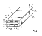
FIG. 2 is a perspective view of a thermoelectric conversion unit; -
FIG. 3 is a perspective view of the thermoelectric conversion unit during assembly; -
FIG. 4 is a cross-sectional view taken along line IV-IV inFIG. 2 ; -
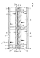
FIG 5 is a cross-sectional view taken along line V-V inFIG. 2 ; -
FIG. 6 is a perspective view of a thermoelectric conversion unit during assembly; -
FIG. 7 is a cross-sectional view taken along line VII-VII inFIG 6 ; -
FIG. 8 is a perspective view of a thermoelectric conversion unit during assembly; -
FIG. 9 is a cross-sectional view taken along line IX-IX inFIG. 8 ; -
FIG. 10 is a cross-sectional view corresponding toFIG 5 with the other configuration; -
FIG. 11 is a cross-sectional view corresponding toFIG. 5 with the other configuration; -
FIG. 12 is a cross-sectional view corresponding toFIG. 5 with the other configuration; and -
FIG. 13 is a top view of a thermoelectric conversion unit and a frame. - Each of the additional features and teachings disclosed above and below may be utilized separately or in conjunction with other features and teachings to provide improved thermoelectric conversion units. Representative examples of the present invention, which utilize many of these additional features and teachings both separately and in conjunction with one another, will now be described in detail with reference to the attached drawings. This detailed description is merely intended to teach a person of ordinary skill in the art further details for practicing preferred aspects of the present teachings and is not intended to limit the scope of the invention. Only the claims define the scope of the claimed invention. Therefore, combinations of features and steps disclosed in the following detailed description may not be necessary to practice the invention in the broadest sense, and are instead taught merely to particularly describe representative examples of the invention. Moreover, various features of the representative examples and the dependent claims may be combined in ways that are not specifically enumerated in order to provide additional useful configurations of the present teachings.
- Referring now to
FIGS. 1 to 5 , an embodiment of the present invention will be described. Aheat exchange system 10 is provided, for example, on a vehicle, and as shown inFIG. 1 , may include athermoelectric conversion unit 1, aradiator 11 and anindoor heat exchanger 14. Theradiator 11 may be connected to anengine 12 of the vehicle bypiping 20. An outdoor heat medium (coolant liquid) may circulate between theengine 12 and theradiator 11 by apump 13 provided at a midpoint of thepiping 20. The outdoor heat medium receives heat from theengine 12 and radiates the heat from theradiator 11 to the outside. - The
thermoelectric conversion unit 1 may be connected to theradiator 11 bypiping 21 connected to thepiping 20 as shown inFIG. 1 , and may be connected to theradiator 11 in parallel to theengine 12. The outdoor heat medium is cooled upon reception of cold from thethermoelectric conversion unit 1 via thepiping radiator 11 but also by thethermoelectric conversion unit 1. - The
thermoelectric conversion unit 1 may be connected to theindoor heat exchanger 14 bypiping 22 as shown inFIG 1 . An indoor heat medium (coolant liquid) may circulate between thethermoelectric conversion unit 1 and theindoor heat exchanger 14 by apump 15 provided at a midpoint of thepiping 22. The indoor heat medium may receive heat from thethermoelectric conversion unit 1, and radiate the heat to indoor air from theindoor heat exchanger 14. Therefore, the indoor air can be heated by theindoor heat exchanger 14. - The
thermoelectric conversion unit 1 includes acase 3 and preferably a plurality (two, for example) ofthermoelectric conversion modules 2 as shown inFIGS. 2 and3 . Thecase 3 preferably has a cylindrical shape and an internal space formed in thecase 3. Thecase 3 preferably includes atop panel 3a, abottom panel 3b, andside panels front panel 3e is preferably provided between front portions of theside panels rear panel 3f is preferably provided between rear portions of theside panels center panel 3g is preferably provided between center portions of theside panels - As shown in
FIGS. 3 and4 , thefront panel 3e, therear panel 3f, and thecenter panel 3g are preferably positioned between thetop panel 3a and thebottom panel 3b. They are preferably positioned so that twoflow channels top panel 3a and thebottom panel 3b. Inner side surfaces of thefront panel 3e and the rear panel 3fmay be formed with depressed portions 3el and 3fl. The depressed portions 3el and 3fl may be formed over the entire length of thefront panel 3e and therear panel 3f in the longitudinal direction. Thecenter panel 3g preferably has both inner side surfaces opposing thefront panel 3e and therear panel 3f. Depressed portions 3gl may be formed on the both inner side surfaces. The depressed portions 3gl may be formed over the entire length of thecenter panel 3g in the longitudinal direction. - As shown in
FIG. 5 , large depressed portions 3c2 and 3d2 and depressed portions 3c1 and 3d1 are preferably formed on the inner peripheral surfaces of theside panels side panels side panels side panels FIG. 3 thethermoelectric conversion module 2 is preferably inserted into thecase 3 in a state in which theside panel 3d is removed. - As shown in
FIGS. 4 and5 , thethermoelectric conversion module 2 preferably includesthermoelectric conversion elements 2a,substrates fins thermoelectric conversion element 2a achieves a Peltier effect by using a DC electricity. Of the two heating surfaces, at least one heating surface absorbs heat as a heat-absorbing portion, while the at least other one radiates heat as a heat-radiating portion. A plurality ofthermoelectric conversion elements 2a may be provided between thesubstrates thermoelectric conversion elements 2a are preferably arranged in a plurality of rows in the vertically and laterally planar directions with respect to thesubstrates - The
substrates FIG. 4 , and are made from an insulative material. Thesubstrates thermoelectric conversion elements 2a may be soldered on the electrodes 2b3 and 2c3. - The
substrates case 3 by being inserted into thecase 3 as shown inFIGS. 3 and4 . The internal space of thecase 3 may be partitioned into thefirst flow channel 3h by thefirst substrate 2b and the internal space of thecase 3 may be partitioned into thesecond flow channel 3i by thesecond substrate 2c. In other words, thefirst flow channel 3h and thesecond flow channel 3i are formed having an opened structure in the interior of thecase 3. An opening portion of thefirst flow channel 3h may be covered with thefirst substrate 2b and an opening portion of thesecond flow channel 3i may be covered with thesecond substrate 2c. Thefirst flow channel 3h and thesecond flow channel 3i include inlet ports 3h1 and 3il at one end portion of thecase 3 and exits 3h2 and 3i2 at the other end of thecase 3. - As shown in
FIGS. 3 and5 , thefins substrates fins flow channels substrates fins flow channels flow channels - A
frame member 4 may be mounted on outer peripheral portions of thesubstrates FIGS. 3 to 5 . Theframe member 4 is preferably made of a rubber or a resin having a large elastic deformation potential. Theframe member 4 integrally includes aframe body 4a, a projectingportion 4b, and an inner projectingportion 4c. An inner peripheral portion of theframe body 4a preferably has an annular shape and preferably comes into tight contact with the entire outer peripheries of thesubstrates frame body 4a preferably seals a portion between the outer peripheral portions of thesubstrates thermoelectric conversion elements 2a from the heat medium or the outside air. - The inner projecting
portion 4c may project from theframe body 4a to between thesubstrates portion 4c may project from the entire circumference of an inner peripheral surface of theframe body 4a. The inner projectingportion 4c is preferably in close proximity to or abuts the inner surfaces 2b2 and 2c2 of thesubstrates portion 4c preferably restricts thesubstrates thermoelectric conversion elements 2a from collapsing. - The projecting
portion 4b may project outward from theframe body 4a as shown inFIGS. 3 and4 . The projectingportion 4b preferably projects from the entire periphery of an outer peripheral surface of theframe body 4a. The projectingportion 4b may be inserted into the depressed portions 3el to 3gl from the sides of thecase 3 from which theside panel 3d is removed. The projectingportion 4b may be inserted into thecase 3 while being guided to the depressed portions 3el to 3gl. Theframe member 4 and thethermoelectric conversion module 2 are preferably inserted into thecase 3. - As shown in
FIGS 4 and5 , the projectingportion 4b may also be inserted into the depressed portions 3c1 and 3d1 of theside panels frame member 4 preferably opposes aperipheral wall portion 3j (theside panels front panel 3e, therear panel 3f, and thecenter panel 3g) of thecase 3 and preferably comes into tight contact with the entire periphery with respect to theperipheral wall portion 3j. Accordingly, theframe member 4 may cooperate with thesubstrates case 3 into theflow channels - When manufacturing the
thermoelectric conversion unit 1, theframe member 4 may be mounted on thethermoelectric conversion module 2 as shown inFIG. 3 . Thethermoelectric conversion module 2 can be slid and inserted into thecase 3 together with theframe member 4. As shown inFIG. 2 , theside panel 3d of thecase 3 may be mounted on a case body. A converter, not illustrated, may be electrically connected to thethermoelectric conversion unit 1. The converter supplies a DC electricity to thethermoelectric conversion unit 1, and the DC electricity flows in series through the plurality ofthermoelectric conversion elements 2a by the electrodes 2b3 and 2c3. With the supply of the electric current, thethermoelectric conversion elements 2a can absorb heat via thesecond substrate 2c and thesecond fin 2e and radiate the heat via thefirst substrate 2b and thefirst fin 2d. - The
second flow channel 3i of thethermoelectric conversion unit 1 may be connected to the piping 21 as shown inFIG. 1 . The outdoor heat medium is supplied to thesecond flow channel 3i by thepump 13 via thepiping second flow channel 3i as shown inFIG. 4 . The outdoor heat medium preferably flows in thesecond flow channel 3i, is cooled by from thesecond substrate 2c and thesecond fin 2e, and is discharged from the exit 3i2 to the outside of thesecond flow channel 3i. - The
first flow channel 3h of thethermoelectric conversion unit 1 is preferably connected to the piping 22 as shown inFIG 1 . The indoor heat medium is supplied to thefirst flow channel 3h by thepump 15 via thepiping 22. The indoor heat medium flows in thefirst flow channel 3h from the inlet port 3hl as shown inFIG. 4 , thereby receiving heat from thefirst substrate 2b and thefirst fin 2d. The indoor heat medium is discharged from the exit 3h2 to the outside of thefirst flow channel 3h, and flows in theindoor heat exchanger 14 shown inFIG 1 . Theindoor heat exchanger 14 discharges the heat to the air in the interior of the chamber. - As described above, the
thermoelectric conversion unit 1 preferably includes the pair ofsubstrates thermoelectric conversion elements 2a provided between the pair ofsubstrates frame member 4 and thecase 3 as shown inFIGS. 4 and5 . Theframe member 4 may be mounted on and along the outer peripheral portion of the pair ofsubstrates case 3 is preferably formed with theflow channels flow channels substrates case 3 includes theperipheral wall portion 3j (3c to 3g) configured to cover the outer peripheral portion of theframe member 4. Theperipheral wall portion 3j of thecase 3 and the outer peripheral portion of theframe member 4 preferably come into tight contact with each other to achieve sealing. - The
frame member 4 preferably holds the pair of thesubstrates substrates thermoelectric conversion elements 2a. Theframe member 4 may be easily configured due to its structure extending along the outer peripheral portions of the pair ofsubstrates case 3 and theframe member 4 may be brought into tight contact with each other, and hence be securely mounted with each other. - The
frame member 4 may include an inner peripheral portion contacting the circumferences of the respective outer peripheral portions of the pair ofsubstrates peripheral wall portion 3j of thecase 3 as shown inFIGS. 4 and5 . Therefore, the inner peripheral portion of theframe member 4 can protect thethermoelectric conversion elements 2a from the heat medium or the outside air through sealing a portion between the pair ofsubstrates frame member 4 is preferably positioned between thecase 3 and thesubstrates case 3 and thesubstrates frame member 4 forms theflow channels substrates - As shown in
FIGS. 4 and5 , theperipheral wall portion 3j of thecase 3 may be formed with the depressed portions 3c1 to 3g1. Theframe member 4 preferably has a projectingportion 4b which can be inserted into the depressed portions 3c1 to 3g1. Thecase 3 and theframe member 4 can be securely mounted using the depressed portions 3c1 to 3gl and the projectingportion 4b. - The
case 3 may be provided with a tubular member formed with opening portions at both ends thereof as shown inFIGS. 3 and4 . The depressed portions 3c1 to 3g1 extending in the axial direction of the tubular member may be formed on the inner peripheral portion of thecase 3. The depressed portions 3c1 to 3g1 preferably reach both opening portions of thecase 3, Therefore, by using the depressed portions 3e1 to 3g1 and the projectingportion 4b, theframe member 4 and thecase 3 can be mounted using a sliding movement. - As shown in
FIGS. 3 and4 an internal space configured to store a pair ofsubstrates frame member 4 may be formed in thecase 3. The internal space includes afirst flow channel 3h partitioned by thefirst substrate 2b and theframe member 4, and asecond flow channel 3i partitioned by thesecond substrate 2c and theframe member 4. Therefore, theframe member 4 forms the twoflow channels case 3 through use of thesubstrates - While the embodiments of invention have been described with reference to specific configurations, it will be apparent to those skilled in the art that many alternatives, modifications and variations may be made without departing from the scope of the present invention. Accordingly, embodiments of the present invention are intended to embrace all such alternatives, modifications and variations that may fall within the spirit and scope of the appended claims. For examples, embodiments of the present invention should not be limited to the representative configurations, but may be modified, for example, as described below.
- The
thermoelectric conversion unit 1 may have acase 5 as shown inFIGS. 6 and7 instead of thecase 3 shown inFIG. 3 . As shown inFIGS. 6 and7 , thecase 5 may have a cylindrical shape and can be formed with an internal space in thecase 5. Thecase 5 may include atop panel 5a, abottom panel 5b, andside panels front panel 5e is preferably provided between front portions of theside panels rear panel 5f is preferably provided between rear portions of theside panels rear panel 5f may be positioned between thetop panel 5a and thebottom panel 5b. - As shown in
FIG 6 , depressed portions 5c1 and 5dl may be formed on inner side surfaces of theside panels side panels side panels FIG. 7 , depressed portions 5el and 5fl may be formed on inner side surfaces of thefront panel 5e and therear panel 5f. The depressed portions 5el and 5fl are positioned at substantially the centers of the height of thefront panel 5e and therear panel 5f, and may be formed over the entire length of thefront panel 5e and therear panel 5f in the longitudinal direction. - As shown in
FIG. 6 , thethermoelectric conversion module 2 and theframe member 4 may be inserted into thecase 5 from the front or rear of thecase 5 such that thefront panel 5e or therear panel 5f can be removed. Theframe member 4 may be inserted into thecase 5 while the projectingportion 4b of theframe member 4 is guided into the depressed portions 5c1, and 5dl of theside panels FIG. 7 , the twothermoelectric conversion modules 2 are preferably located adjacent to each other in thecase 5. Further, the projectingportions 4b of theframe members 4 mounted on the respectivethermoelectric conversion modules 2 preferably come into tight contact with each other. - As shown in
FIGS. 6 and7 , thefront panel 5e and therear panel 5f may be mounted on theside panels portion 4b of theframe member 4 may be inserted into the depressed portion 5el of thefront panel 5e and the depressed portion 5f1 of therear panel 5f. Thecase 5 preferably includes aperipheral portion 5j (5c, 5d, 5e and 5f) configured to cover the outer peripheral portions of theframe members 4. The outer peripheral surfaces of theframe members 4 preferably come into tight contact with theperipheral wall portions 5j. Accordingly, theframe members 4 and thethermoelectric conversion modules 2 may formflow channels case 5. - The
thermoelectric conversion unit 1 may include aframe member 6 shown inFIGS. 8 and9 instead of theframe member 4 shown inFIGS. 6 and7 . As shown inFIGS. 8 and9 , theframe member 6 may integrally include aframe body 6a, a projectingportion 6b, and an inner projectingportion 6c. Theframe body 6a may include an annular outer frame portion 6al and a compartmentalizing portion 6a2 compartmentalizing an inner area of the outer frame portion 6al into a plurality of compartments. - The
frame member 6 may be formed with a plurality of opening portions 6a3 by the outer frame portion 6a1 and the compartmentalizing portion 6a2. The respectivethermoelectric conversion modules 2 may be mounted on the respective opening portions 6a3. An inner projectingportion 6c preferably projects between thesubstrates frame body 6a. The inner projectingportions 6c are preferably formed on both surfaces, i.e., the inner peripheral surfaces of the outer same portion 6al and the compartmentalizing portion 6a2. - As shown in
FIGS. 8 and9 , the projectingportion 6b may be inserted into the depressed portions 5c1 and 5d1 of theside panels case 5 such that thefront panel 5e or the rear panel Sf can be removed by a sliding movement. Thefront panel 5e and therear panel 5f may be mounted on the front or rear portion of thecase 5. The projectingportion 6b of theflame member 6 can be inserted into the depressed portions 5el and 5fl of thefront panel 5e and therear panel 5f. Theframe member 6 preferably comes into tight contact with the circumference of theperipheral wall portion 5j (5c, 5d, 5e and 5f) of thecase 5. Accordingly, theframe member 6 preferably forms theflow channels case 5 in cooperation with thethermoelectric conversion modules 2. - The
thermoelectric conversion unit 1 may have acase 7 as shown inFIG. 10 instead of thecase 3 shown inFIG. 5 . Thecase 7 may include afirst case 7a and asecond case 7b as shown inFIG. 10 . Thefirst case 7a and thesecond case 7b are preferably stacked in layers and cooperate each other to configure a cylindrical shape. The cylindrical shape is similar to the cylindrical shape of thecase 3 shown inFIGS. 3 to 5 . - As shown in
FIG. 10 , depressed portions 7al and 7bl, which constituteflow channels 7h and 7i having an opened structure, may be formed on thefirst case 7a and thesecond case 7b. Opening portions of theflow channels 7h and 7i may be covered with thesubstrates first case 7a may have a peripheral wall portion 7a4 configured to cover an outer periphery of theframe member 4. The peripheral wall portion 7a4 can be formed with a large depressed portion 7a3 and a depressed portion 7a2. The large depressed portion 7a3 is preferably formed over the entire length of a side wall of thefirst case 7a. Theframe member 4 and outer peripheral end portions of thesubstrates - As shown in
FIG. 10 , the depressed portion 7a2 may be formed so as to be depressed on a bottom surface of the large depressed portion 7a3. The depressed portion 7a2 is preferably formed over the entire length of a side wall of thefirst case 7a. The projectingportion 4b of theframe member 4 may be inserted into the depressed portion 7a2. Theframe member 4 can be mounted in thefirst case 7a using the projectingportion 4b and the depressed portion 7a2 by a sliding movement. Thesecond case 7b may be placed on top of thefirst case 7a. Thesecond case 7b may have an opposed wall portion 7b2 opposing theframe member 4 and a peripheral wall portion 7a4 on an outer periphery of the second flow channel 7i. Mounted on thefirst case 7a may be a front panel and a rear panel formed in the same manner as thefront panel 5e and therear panel 5f shown inFIG 6 . - The
thermoelectric conversion unit 1 may have thecase 7 and theframe member 4 shown inFIG. 11 instead of thecase 7 and theframe member 4 shown inFIG 10 . Thecase 7 shown inFIG. 11 is not formed with the depressed portion 7a2 shown inFIG 10 , but is formed with depressed portions 7a5 and 7a7 and a projecting portion 7a6. The depressed portions 7a5 and 7a7 are formed so as to be depressed on the bottom surface of the large depressed portion 7a3. The projecting portion 7a6 projects toward theframe member 4 from the bottom surface of the large depressed portion 7a3. - The
frame member 4 shown inFIG 11 is not formed with the projectingportion 4b shown inFIG. 10 but is preferably formed with projectingportions depressed portion 4e. The projectingportions case 7. The projecting portion 7a6 of thecase 7 may be slidably inserted into thedepressed portion 4e. Theframe member 4 can be mounted on thefirst case 7a using the projectingportions depressed portions 4e, 7a5 and 7a7 via a sliding movement. - The
thermoelectric conversion unit 1 may have theframe member 4 and thecase 7 shown inFIG. 12 instead of theframe member 4 and thecase 7 shown inFIG. 10 . Theframe member 4 shown inFIG 12 includes asealing projecting portion 4g in addition to the configuration shown inFIG. 10 . The opposed wall portion 7b2 of thesecond case 7b is formed with a depressed portion 7b3 in which thesealing projecting portion 4g is inserted. Thesealing projecting portion 4g may come into resilient contact with thesecond case 7b by placing thesecond case 7b on thefirst case 7a. In such a way, the portion between theframe member 4 and thesecond case 7b may be sealed. - As described above and shown in
FIG. 12 , thecase 7 preferably includes afirst case 7a formed with afirst flow channel 7h and asecond case 7b formed with a second flow channel 7i. Thefirst case 7a may have a peripheral wall portion 7a4. Thesecond case 7b may have an opposed wall portion 7b2 opposing the peripheral wall portion 7a4 and theframe member 4. Theframe member 4 may be provided with asealing projecting portion 4g projecting toward the opposed wall portion 7b2 and configured to seal the portion between theframe member 4 and the opposed wall portion 7b2 by coming into resilient contact with the opposed wall portion 7b2. Therefore, thesealing projecting portion 4g can be resiliently deformed by placing thesecond case 7b on thefirst case 7a, and is capable of sealing the portion between thesecond case 7b and theframe member 4. - The
frame member 4 may have four corners at substantially right angles as shown inFIG. 3 , or may have arcuate portions 4al and 4bl as shown inFIG. 13 . The arcuate portions 4al may be formed at the four corners of theframe body 4a. The arcuate portions 4bl are formed at four corners of the projectingportion 4b. Thecase 3 may be formed with arcuate portions having a shape corresponding to the arcuate portions 4al and 4bl of theframe member 4. Using such a construction, the four corners of theframe 4 are able to withstand concentrated forces applied to them. In this manner, the sealing property of the portion between theframe member 4 and thecase 3 can be improved. - The
thermoelectric conversion unit 1 may have any number of thethermoelectric conversion modules 2. - The
case 3 may be formed with one or more flow channels. As shown inFIGS. 10 and 11 , thecase 7 may only have thefirst case 7a without having thesecond case 7b. - The
thermoelectric conversion elements 2a may be Peltier elements providing a Peltier effect, or may be elements which provide a Seebeck Effect or a Thomson Effect. - A
case 3 may be formed with the depressed portions 3c1 to 3g1 on theperipheral wall portion 3j and aframe member 4 may be formed with a projectingportion 4b. Alternatively, acase 3 may be formed without the depressed portions 3c1 to 3g1, and theframe member 4 may be formed without the depressed portions 3c1 to 3g1. Theperipheral wall portion 3j of thecase 3 and the outer peripheral portion of theframe member 4 may be brought into tight contact with each other to create a sealing effect. - As shown in
FIG. 12 , thesealing projecting portion 4g may be formed on theframe member 4. Alternatively, the seal projecting portion may be formed on the opposed wall portion 7b2 of thesecond case 7b. Theframe member 4 may be formed with the depressed portion for allowing insertion of the seal projecting portion. - The
heat exchange system 10 may be used for heating or cooling a cabin of the vehicle. When used for cooling, thefirst flow channel 3h is preferably connected to thepiping 21 and thesecond flow channel 3i is preferably connected to thepiping 22. Theheat exchange system 10 may be used for cooling or heating vehicle components such as a battery. It is contemplated that theheat exchange system 10 may be used for heating and/or cooling objects and components outside of the vehicle industry.
Embodiments of the present invention may include a thermoelectric conversion unit (1) having a pair of substrates (2b, 2c) opposing each other, thermoelectric conversion element (2a)s provided between the pair of substrates (2b, 2c), a frame member (4; 6), and a case (3; 5; 7). The frame member (4; 6) may be mounted along an outer peripheral portion of the pair of substrates (2b, 2c). The case (3; 5; 7) may be formed with flow channel (3h, 3i; 5h, 5i, 7h, 7i)s having an opened structure. Opening portions of the flow channel (3h, 3i; 5h, 5i; 7h, 7i)s may be covered with the substrates (2b, 2c). The case (3; 5; 7) may include a peripheral wall portion (3j; 5j; 7a4) configured to cover the outer peripheral portion of the frame member (4; 6). The peripheral wall portion (3j; 5j; 7a4) of the case (3; 5; 7) and the outer peripheral portion of the frame member (4; 6) preferably tightly contact each other to achieve sealing.
Claims (6)
- A thermoelectric conversion unit (1) comprising:a pair of substrates (2b, 2c) opposing each other,a thermoelectric conversion element (2a) provided between the pair of substrates (2b, 2c),a frame member (4; 6) mounted along an outer peripheral portion of the pair of substrates (2b, 2c), anda case (3; 5; 7) formed with a flow channel (3h, 3i; 5h, 5i; 7h, 7i) having an opened structure, and whose opening portion of the flow channel (3h, 3i; 5h, 5i; 7h, 7i) is covered with one of the substrates (2b, 2c),wherein the case (3; 5; 7) comprises a peripheral wall portion (3j; 5j; 7a4) configured to cover the outer peripheral portion of the frame member (4; 6), wherein the peripheral wall portion (3j; 5j; 7a4) of the case (3; 5; 7) and the outer peripheral portion of the frame member (4; 6) contact each other to achieve sealing.
- A thermoelectric conversion unit (1) as in claim 1, wherein the frame member (4; 6) comprises an inner peripheral portion which contacts the entire circumferences of the respective outer peripheral portions of the pair of substrates (2b, 2c), and an outer peripheral portion which contacts the entire circumference of the peripheral wall portion (3j; 5j; 7a4) of the case (3; 5; 7).
- A thermoelectric conversion unit (1) as in claim 1 or 2, further comprising a depressed portion (3cl-3gl; 4e; 5cl-5fl; 7a5, 7a7) wherein the depressed portion (3cl-3gl; 4e; 5cl-5fl; 7a5, 7a7) is formed either of the peripheral wall portion (3j; 5j; 7a4) of the case (3; 5; 7) or the outer peripheral portion of the frame member (4; 6), and a projecting portion (4b, 4d, 4f; 6b; 7a6) wherein the projecting portion (4b, 4d, 4f; 6b; 7a6) is formed either of the peripheral wall portion (3j; Sj; 7a4) of the case (3; 5; 7) or the outer peripheral portion of the frame member (4; 6), and wherein the projecting portion (4b, 4d, 4f; 6b; 7a6) may be inserted into the depressed portion (3cl-3gl; 4e; 5cl-5fl; 7a5, 7a7).
- A thermoelectric conversion unit (1) as in claim 3,
wherein the case (3; 5; 7) is provided with a tubular member,
wherein the tubular member is formed with opening portions at both ends thereof, wherein formed on the inner peripheral portion of the tubular member is either the depressed portion (3c1-3g1; 4e; 5c1-5f1; 7a5, 7a7) or projecting portion (4b, 4d, 4f; 6b; 7a6), such portion extending in an axial direction of the tubular member, wherein such portion extends to both opening portions of the tubular member. - A thermoelectric conversion unit (1) as in one of claims 1 to 4, further comprising:an internal space configured in the case (3; 5; 7) to store the pair of substrates (2b, 2c) and the frame member (4; 6),a first flow channel (3h; 5h; 7h) created in the internal space by the frame member (4; 6) and one of the substrates (2b, 2c), anda second flow channel (3i; 5i; 7i) created in the internal space by the frame member (4; 6) and the other of the substrates (2b, 2c).
- A thermoelectric conversion unit (1) as in one of claims 1 to 5,
wherein the case (7) comprises a first case (7a) formed with a first flow channel (7h) and a second case (7b) formed with a second flow channel (7i),
wherein the second case (7b) comprises an opposed wall portion (7b2) opposing the frame member (4),
wherein either the frame member (4) or the opposed wall portion (7b2) is provided with a sealing projecting portion (4g), the sealing projecting portion (4g) configured to seal the frame member (4) and the opposed wall portion (7b2), such that the frame member (4) and the opposed wall portion (7b2) come into resilient contact with each other.
Applications Claiming Priority (1)
| Application Number | Priority Date | Filing Date | Title |
|---|---|---|---|
| JP2011138651A JP2013008734A (en) | 2011-06-22 | 2011-06-22 | Thermoelectric conversion unit |
Publications (1)
| Publication Number | Publication Date |
|---|---|
| EP2538464A2 true EP2538464A2 (en) | 2012-12-26 |
Family
ID=46466109
Family Applications (1)
| Application Number | Title | Priority Date | Filing Date |
|---|---|---|---|
| EP12171256A Withdrawn EP2538464A2 (en) | 2011-06-22 | 2012-06-08 | Thermoelectric conversion units |
Country Status (3)
| Country | Link |
|---|---|
| US (1) | US20120325280A1 (en) |
| EP (1) | EP2538464A2 (en) |
| JP (1) | JP2013008734A (en) |
Families Citing this family (6)
| Publication number | Priority date | Publication date | Assignee | Title |
|---|---|---|---|---|
| JP6306478B2 (en) * | 2014-09-05 | 2018-04-04 | 京セラ株式会社 | Thermoelectric module and thermoelectric device |
| USD816198S1 (en) * | 2015-01-28 | 2018-04-24 | Phononic, Inc. | Thermoelectric heat pump |
| JP6595320B2 (en) * | 2015-11-27 | 2019-10-23 | 京セラ株式会社 | Thermoelectric module assembly |
| DE102016209683A1 (en) * | 2016-06-02 | 2017-12-07 | Mahle International Gmbh | Thermoelectric module |
| USD833588S1 (en) | 2017-10-11 | 2018-11-13 | Phononic, Inc. | Thermoelectric heat pump |
| JP2019143621A (en) * | 2017-12-20 | 2019-08-29 | マグネティ マレッリ ソチエタ ペル アツィオニ | Intercooler with thermoelectric generator for internal combustion heat engine with turbocharger |
Citations (2)
| Publication number | Priority date | Publication date | Assignee | Title |
|---|---|---|---|---|
| JP2001004245A (en) | 1999-06-18 | 2001-01-12 | Daikin Ind Ltd | Thermoelectric converter |
| JP2001119076A (en) | 1999-08-10 | 2001-04-27 | Matsushita Electric Works Ltd | Thermoelectric conversion module and method of manufacturing the same |
Family Cites Families (2)
| Publication number | Priority date | Publication date | Assignee | Title |
|---|---|---|---|---|
| JP2008034791A (en) * | 2006-06-28 | 2008-02-14 | Denso Corp | Thermoelectric conversion device and method of manufacturing the same |
| US20100147351A1 (en) * | 2007-07-20 | 2010-06-17 | Universal Entertainment Corporation | Thermoelectric conversion module |
-
2011
- 2011-06-22 JP JP2011138651A patent/JP2013008734A/en not_active Withdrawn
-
2012
- 2012-06-08 EP EP12171256A patent/EP2538464A2/en not_active Withdrawn
- 2012-06-18 US US13/525,666 patent/US20120325280A1/en not_active Abandoned
Patent Citations (2)
| Publication number | Priority date | Publication date | Assignee | Title |
|---|---|---|---|---|
| JP2001004245A (en) | 1999-06-18 | 2001-01-12 | Daikin Ind Ltd | Thermoelectric converter |
| JP2001119076A (en) | 1999-08-10 | 2001-04-27 | Matsushita Electric Works Ltd | Thermoelectric conversion module and method of manufacturing the same |
Also Published As
| Publication number | Publication date |
|---|---|
| US20120325280A1 (en) | 2012-12-27 |
| JP2013008734A (en) | 2013-01-10 |
Similar Documents
| Publication | Publication Date | Title |
|---|---|---|
| EP1384271B1 (en) | Electric cooling device | |
| CN107940889B (en) | Apparatus for generating cold water and water purifier | |
| US20120325280A1 (en) | Thermoelectric conversion units | |
| US9627724B2 (en) | Battery pack having a cooling plate assembly | |
| US20110044001A1 (en) | Cooling device for a plurality of power modules | |
| US20160036102A1 (en) | Battery Module | |
| US20160172726A1 (en) | Receiving device for receiving at least one energy storage component | |
| KR102351954B1 (en) | heat exchanger for cooling electric element | |
| KR101473899B1 (en) | A Heat Exchanger using Thermoelectric Modules | |
| WO2017031596A1 (en) | Heat exchanger with plate-like conduits for cooling electronic components | |
| KR101293349B1 (en) | Thermoelectric conversion unit | |
| US9172122B2 (en) | Battery module | |
| US20120247526A1 (en) | Thermoelectric conversion unit and method of manufacturing | |
| US20160156080A1 (en) | Receiving device for receiving at least one energy storage component | |
| KR20130112899A (en) | Temperature-controlled battery | |
| EP2500682A2 (en) | Heat exchanger | |
| JP7255453B2 (en) | circuit construct | |
| CN107343384A (en) | Storage group | |
| US20180115028A1 (en) | Cooling system for cooling electrochemical cells of a battery system | |
| US11752852B2 (en) | Traction battery module | |
| US12041748B2 (en) | Cooling apparatus | |
| KR101307518B1 (en) | Thermoelectric generator device | |
| JP2013008737A (en) | Thermoelectric conversion unit | |
| US11081741B2 (en) | Battery module and battery | |
| CN107004512B (en) | Power storage module |
Legal Events
| Date | Code | Title | Description |
|---|---|---|---|
| PUAI | Public reference made under article 153(3) epc to a published international application that has entered the european phase |
Free format text: ORIGINAL CODE: 0009012 |
|
| 17P | Request for examination filed |
Effective date: 20120711 |
|
| AK | Designated contracting states |
Kind code of ref document: A2 Designated state(s): AL AT BE BG CH CY CZ DE DK EE ES FI FR GB GR HR HU IE IS IT LI LT LU LV MC MK MT NL NO PL PT RO RS SE SI SK SM TR |
|
| AX | Request for extension of the european patent |
Extension state: BA ME |
|
| STAA | Information on the status of an ep patent application or granted ep patent |
Free format text: STATUS: THE APPLICATION HAS BEEN WITHDRAWN |
|
| 18W | Application withdrawn |
Effective date: 20130416 |