EP2538422A1 - Dye-sensitized solar cell and fabrication process thereof - Google Patents
Dye-sensitized solar cell and fabrication process thereof Download PDFInfo
- Publication number
- EP2538422A1 EP2538422A1 EP12173177A EP12173177A EP2538422A1 EP 2538422 A1 EP2538422 A1 EP 2538422A1 EP 12173177 A EP12173177 A EP 12173177A EP 12173177 A EP12173177 A EP 12173177A EP 2538422 A1 EP2538422 A1 EP 2538422A1
- Authority
- EP
- European Patent Office
- Prior art keywords
- layer
- substrate
- titanium
- nanostructure
- cell
- Prior art date
- Legal status (The legal status is an assumption and is not a legal conclusion. Google has not performed a legal analysis and makes no representation as to the accuracy of the status listed.)
- Withdrawn
Links
- 238000000034 method Methods 0.000 title claims abstract description 55
- 230000008569 process Effects 0.000 title claims abstract description 51
- 238000004519 manufacturing process Methods 0.000 title claims description 15
- 239000000758 substrate Substances 0.000 claims abstract description 103
- 239000002071 nanotube Substances 0.000 claims abstract description 102
- 239000002086 nanomaterial Substances 0.000 claims abstract description 67
- 239000000463 material Substances 0.000 claims abstract description 63
- GWEVSGVZZGPLCZ-UHFFFAOYSA-N Titan oxide Chemical compound O=[Ti]=O GWEVSGVZZGPLCZ-UHFFFAOYSA-N 0.000 claims abstract description 59
- 239000003792 electrolyte Substances 0.000 claims abstract description 33
- 239000004408 titanium dioxide Substances 0.000 claims abstract description 27
- 239000010410 layer Substances 0.000 claims description 208
- 239000010936 titanium Substances 0.000 claims description 97
- RTAQQCXQSZGOHL-UHFFFAOYSA-N Titanium Chemical compound [Ti] RTAQQCXQSZGOHL-UHFFFAOYSA-N 0.000 claims description 75
- 229910052719 titanium Inorganic materials 0.000 claims description 75
- LFQSCWFLJHTTHZ-UHFFFAOYSA-N Ethanol Chemical compound CCO LFQSCWFLJHTTHZ-UHFFFAOYSA-N 0.000 claims description 16
- 230000001590 oxidative effect Effects 0.000 claims description 16
- 238000000151 deposition Methods 0.000 claims description 14
- 230000008021 deposition Effects 0.000 claims description 8
- 239000003960 organic solvent Substances 0.000 claims description 8
- 239000011241 protective layer Substances 0.000 claims description 8
- -1 fluoride ions Chemical class 0.000 claims description 7
- 230000003647 oxidation Effects 0.000 claims description 6
- 238000007254 oxidation reaction Methods 0.000 claims description 6
- 238000007598 dipping method Methods 0.000 claims description 5
- 239000008139 complexing agent Substances 0.000 claims description 4
- 150000002148 esters Chemical class 0.000 claims description 3
- 150000003949 imides Chemical class 0.000 claims description 3
- 238000004544 sputter deposition Methods 0.000 claims description 3
- 239000004020 conductor Substances 0.000 claims 1
- 238000002048 anodisation reaction Methods 0.000 description 54
- 239000010408 film Substances 0.000 description 12
- 229920001721 polyimide Polymers 0.000 description 12
- 239000004642 Polyimide Substances 0.000 description 11
- 229910052751 metal Inorganic materials 0.000 description 10
- 239000002184 metal Substances 0.000 description 10
- PEDCQBHIVMGVHV-UHFFFAOYSA-N Glycerine Chemical compound OCC(O)CO PEDCQBHIVMGVHV-UHFFFAOYSA-N 0.000 description 9
- 238000010438 heat treatment Methods 0.000 description 8
- 238000002441 X-ray diffraction Methods 0.000 description 6
- 230000015572 biosynthetic process Effects 0.000 description 6
- 238000002425 crystallisation Methods 0.000 description 6
- 230000008025 crystallization Effects 0.000 description 6
- 229920003223 poly(pyromellitimide-1,4-diphenyl ether) Polymers 0.000 description 6
- 230000005855 radiation Effects 0.000 description 6
- 230000009477 glass transition Effects 0.000 description 5
- BASFCYQUMIYNBI-UHFFFAOYSA-N platinum Substances [Pt] BASFCYQUMIYNBI-UHFFFAOYSA-N 0.000 description 5
- 239000012780 transparent material Substances 0.000 description 5
- 238000003491 array Methods 0.000 description 4
- 239000012298 atmosphere Substances 0.000 description 4
- 238000001755 magnetron sputter deposition Methods 0.000 description 4
- SOQBVABWOPYFQZ-UHFFFAOYSA-N oxygen(2-);titanium(4+) Chemical compound [O-2].[O-2].[Ti+4] SOQBVABWOPYFQZ-UHFFFAOYSA-N 0.000 description 4
- 238000001878 scanning electron micrograph Methods 0.000 description 4
- WEVYAHXRMPXWCK-UHFFFAOYSA-N Acetonitrile Chemical compound CC#N WEVYAHXRMPXWCK-UHFFFAOYSA-N 0.000 description 3
- HEMHJVSKTPXQMS-UHFFFAOYSA-M Sodium hydroxide Chemical compound [OH-].[Na+] HEMHJVSKTPXQMS-UHFFFAOYSA-M 0.000 description 3
- LDDQLRUQCUTJBB-UHFFFAOYSA-N ammonium fluoride Chemical compound [NH4+].[F-] LDDQLRUQCUTJBB-UHFFFAOYSA-N 0.000 description 3
- 238000007743 anodising Methods 0.000 description 3
- 239000007864 aqueous solution Substances 0.000 description 3
- 239000002800 charge carrier Substances 0.000 description 3
- 239000011248 coating agent Substances 0.000 description 3
- 238000000576 coating method Methods 0.000 description 3
- 239000013078 crystal Substances 0.000 description 3
- 239000007789 gas Substances 0.000 description 3
- 230000003287 optical effect Effects 0.000 description 3
- 239000004417 polycarbonate Substances 0.000 description 3
- 229920000515 polycarbonate Polymers 0.000 description 3
- 239000000243 solution Substances 0.000 description 3
- 238000012546 transfer Methods 0.000 description 3
- XLYOFNOQVPJJNP-UHFFFAOYSA-N water Chemical compound O XLYOFNOQVPJJNP-UHFFFAOYSA-N 0.000 description 3
- DDFHBQSCUXNBSA-UHFFFAOYSA-N 5-(5-carboxythiophen-2-yl)thiophene-2-carboxylic acid Chemical compound S1C(C(=O)O)=CC=C1C1=CC=C(C(O)=O)S1 DDFHBQSCUXNBSA-UHFFFAOYSA-N 0.000 description 2
- XKRFYHLGVUSROY-UHFFFAOYSA-N Argon Chemical compound [Ar] XKRFYHLGVUSROY-UHFFFAOYSA-N 0.000 description 2
- KRHYYFGTRYWZRS-UHFFFAOYSA-N Fluorane Chemical compound F KRHYYFGTRYWZRS-UHFFFAOYSA-N 0.000 description 2
- KJTLSVCANCCWHF-UHFFFAOYSA-N Ruthenium Chemical group [Ru] KJTLSVCANCCWHF-UHFFFAOYSA-N 0.000 description 2
- 238000010521 absorption reaction Methods 0.000 description 2
- 238000004090 dissolution Methods 0.000 description 2
- 239000008151 electrolyte solution Substances 0.000 description 2
- 238000011049 filling Methods 0.000 description 2
- XMBWDFGMSWQBCA-UHFFFAOYSA-N hydrogen iodide Chemical compound I XMBWDFGMSWQBCA-UHFFFAOYSA-N 0.000 description 2
- 238000005470 impregnation Methods 0.000 description 2
- 239000003504 photosensitizing agent Substances 0.000 description 2
- 229920006393 polyether sulfone Polymers 0.000 description 2
- 229920001343 polytetrafluoroethylene Polymers 0.000 description 2
- 239000004810 polytetrafluoroethylene Substances 0.000 description 2
- 229910052707 ruthenium Inorganic materials 0.000 description 2
- 238000001228 spectrum Methods 0.000 description 2
- WRTMQOHKMFDUKX-UHFFFAOYSA-N triiodide Chemical compound I[I-]I WRTMQOHKMFDUKX-UHFFFAOYSA-N 0.000 description 2
- 238000005406 washing Methods 0.000 description 2
- WCZNKVPCIFMXEQ-UHFFFAOYSA-N 2,3,5,6-tetramethylbenzene-1,4-diamine Chemical compound CC1=C(C)C(N)=C(C)C(C)=C1N WCZNKVPCIFMXEQ-UHFFFAOYSA-N 0.000 description 1
- 229910004613 CdTe Inorganic materials 0.000 description 1
- YCKRFDGAMUMZLT-UHFFFAOYSA-N Fluorine atom Chemical compound [F] YCKRFDGAMUMZLT-UHFFFAOYSA-N 0.000 description 1
- LGRFSURHDFAFJT-UHFFFAOYSA-N Phthalic anhydride Natural products C1=CC=C2C(=O)OC(=O)C2=C1 LGRFSURHDFAFJT-UHFFFAOYSA-N 0.000 description 1
- 239000012327 Ruthenium complex Substances 0.000 description 1
- 239000011358 absorbing material Substances 0.000 description 1
- 230000009471 action Effects 0.000 description 1
- 238000004458 analytical method Methods 0.000 description 1
- 229910052786 argon Inorganic materials 0.000 description 1
- 238000005452 bending Methods 0.000 description 1
- GKPXMGUNTQSFGA-UHFFFAOYSA-N but-2-ynyl 1-methyl-3,6-dihydro-2h-pyridine-5-carboxylate;4-methylbenzenesulfonic acid Chemical compound CC1=CC=C(S(O)(=O)=O)C=C1.CC#CCOC(=O)C1=CCCN(C)C1 GKPXMGUNTQSFGA-UHFFFAOYSA-N 0.000 description 1
- JHIWVOJDXOSYLW-UHFFFAOYSA-N butyl 2,2-difluorocyclopropane-1-carboxylate Chemical compound CCCCOC(=O)C1CC1(F)F JHIWVOJDXOSYLW-UHFFFAOYSA-N 0.000 description 1
- 230000008859 change Effects 0.000 description 1
- 238000006243 chemical reaction Methods 0.000 description 1
- 238000004140 cleaning Methods 0.000 description 1
- 230000007423 decrease Effects 0.000 description 1
- 239000012153 distilled water Substances 0.000 description 1
- 230000000694 effects Effects 0.000 description 1
- 239000012777 electrically insulating material Substances 0.000 description 1
- 238000006056 electrooxidation reaction Methods 0.000 description 1
- 229920002457 flexible plastic Polymers 0.000 description 1
- 229910052731 fluorine Inorganic materials 0.000 description 1
- 239000011737 fluorine Substances 0.000 description 1
- 239000011521 glass Substances 0.000 description 1
- AMGQUBHHOARCQH-UHFFFAOYSA-N indium;oxotin Chemical compound [In].[Sn]=O AMGQUBHHOARCQH-UHFFFAOYSA-N 0.000 description 1
- 238000002347 injection Methods 0.000 description 1
- 239000007924 injection Substances 0.000 description 1
- 238000011835 investigation Methods 0.000 description 1
- 230000031700 light absorption Effects 0.000 description 1
- 239000007788 liquid Substances 0.000 description 1
- 239000006193 liquid solution Substances 0.000 description 1
- 239000003550 marker Substances 0.000 description 1
- 238000005259 measurement Methods 0.000 description 1
- 230000007246 mechanism Effects 0.000 description 1
- 239000000178 monomer Substances 0.000 description 1
- 239000002105 nanoparticle Substances 0.000 description 1
- 239000011941 photocatalyst Substances 0.000 description 1
- 239000004033 plastic Substances 0.000 description 1
- 229920003023 plastic Polymers 0.000 description 1
- 229910052697 platinum Inorganic materials 0.000 description 1
- 239000005020 polyethylene terephthalate Substances 0.000 description 1
- 229920000139 polyethylene terephthalate Polymers 0.000 description 1
- 230000001681 protective effect Effects 0.000 description 1
- 239000010453 quartz Substances 0.000 description 1
- 230000006798 recombination Effects 0.000 description 1
- 238000005215 recombination Methods 0.000 description 1
- 230000001235 sensitizing effect Effects 0.000 description 1
- 238000000926 separation method Methods 0.000 description 1
- VYPSYNLAJGMNEJ-UHFFFAOYSA-N silicon dioxide Inorganic materials O=[Si]=O VYPSYNLAJGMNEJ-UHFFFAOYSA-N 0.000 description 1
- 239000007787 solid Substances 0.000 description 1
- 239000002904 solvent Substances 0.000 description 1
- 230000003595 spectral effect Effects 0.000 description 1
- 238000002798 spectrophotometry method Methods 0.000 description 1
- 239000000126 substance Substances 0.000 description 1
- 239000010409 thin film Substances 0.000 description 1
- XOLBLPGZBRYERU-UHFFFAOYSA-N tin dioxide Chemical compound O=[Sn]=O XOLBLPGZBRYERU-UHFFFAOYSA-N 0.000 description 1
- 229910001887 tin oxide Inorganic materials 0.000 description 1
- 238000004506 ultrasonic cleaning Methods 0.000 description 1
- 238000001429 visible spectrum Methods 0.000 description 1
- 230000003442 weekly effect Effects 0.000 description 1
Images



Classifications
-
- H—ELECTRICITY
- H01—ELECTRIC ELEMENTS
- H01G—CAPACITORS; CAPACITORS, RECTIFIERS, DETECTORS, SWITCHING DEVICES, LIGHT-SENSITIVE OR TEMPERATURE-SENSITIVE DEVICES OF THE ELECTROLYTIC TYPE
- H01G9/00—Electrolytic capacitors, rectifiers, detectors, switching devices, light-sensitive or temperature-sensitive devices; Processes of their manufacture
- H01G9/20—Light-sensitive devices
- H01G9/2027—Light-sensitive devices comprising an oxide semiconductor electrode
- H01G9/2031—Light-sensitive devices comprising an oxide semiconductor electrode comprising titanium oxide, e.g. TiO2
-
- H—ELECTRICITY
- H01—ELECTRIC ELEMENTS
- H01G—CAPACITORS; CAPACITORS, RECTIFIERS, DETECTORS, SWITCHING DEVICES, LIGHT-SENSITIVE OR TEMPERATURE-SENSITIVE DEVICES OF THE ELECTROLYTIC TYPE
- H01G9/00—Electrolytic capacitors, rectifiers, detectors, switching devices, light-sensitive or temperature-sensitive devices; Processes of their manufacture
- H01G9/20—Light-sensitive devices
- H01G9/2059—Light-sensitive devices comprising an organic dye as the active light absorbing material, e.g. adsorbed on an electrode or dissolved in solution
-
- H—ELECTRICITY
- H01—ELECTRIC ELEMENTS
- H01G—CAPACITORS; CAPACITORS, RECTIFIERS, DETECTORS, SWITCHING DEVICES, LIGHT-SENSITIVE OR TEMPERATURE-SENSITIVE DEVICES OF THE ELECTROLYTIC TYPE
- H01G9/00—Electrolytic capacitors, rectifiers, detectors, switching devices, light-sensitive or temperature-sensitive devices; Processes of their manufacture
- H01G9/20—Light-sensitive devices
- H01G9/2095—Light-sensitive devices comprising a flexible sustrate
-
- Y—GENERAL TAGGING OF NEW TECHNOLOGICAL DEVELOPMENTS; GENERAL TAGGING OF CROSS-SECTIONAL TECHNOLOGIES SPANNING OVER SEVERAL SECTIONS OF THE IPC; TECHNICAL SUBJECTS COVERED BY FORMER USPC CROSS-REFERENCE ART COLLECTIONS [XRACs] AND DIGESTS
- Y02—TECHNOLOGIES OR APPLICATIONS FOR MITIGATION OR ADAPTATION AGAINST CLIMATE CHANGE
- Y02E—REDUCTION OF GREENHOUSE GAS [GHG] EMISSIONS, RELATED TO ENERGY GENERATION, TRANSMISSION OR DISTRIBUTION
- Y02E10/00—Energy generation through renewable energy sources
- Y02E10/50—Photovoltaic [PV] energy
- Y02E10/542—Dye sensitized solar cells
-
- Y—GENERAL TAGGING OF NEW TECHNOLOGICAL DEVELOPMENTS; GENERAL TAGGING OF CROSS-SECTIONAL TECHNOLOGIES SPANNING OVER SEVERAL SECTIONS OF THE IPC; TECHNICAL SUBJECTS COVERED BY FORMER USPC CROSS-REFERENCE ART COLLECTIONS [XRACs] AND DIGESTS
- Y02—TECHNOLOGIES OR APPLICATIONS FOR MITIGATION OR ADAPTATION AGAINST CLIMATE CHANGE
- Y02P—CLIMATE CHANGE MITIGATION TECHNOLOGIES IN THE PRODUCTION OR PROCESSING OF GOODS
- Y02P70/00—Climate change mitigation technologies in the production process for final industrial or consumer products
- Y02P70/50—Manufacturing or production processes characterised by the final manufactured product
Definitions
- the present invention relates to a dye-sensitized photovoltaic cell and a relevant process of manufacturing a dye-sensitized photovoltaic cell.
- the present invention discloses a flexible photovoltaic cell and a process of making it.
- TiO 2 titanium dioxide nanostructures
- TiO 2 nanotube arrays due to their properties, which are relevant in applications such as gas sensors, photovoltaic cells, biomedical materials and photocatalysts.
- TiO 2 nanotubes may be manufactured with various methods, including anodic oxidation of titanium films or sheets.
- a composite porous layer consisting of solid nanoparticles (spherical particles in a first portion of the layer and rodlike particles in a second portion of the layer) is sintered on a glass substrate coated with an Au film and is then removed from the substrate by dissolving the metal layer. Subsequently, the nanoporous layer is transferred to a flexible plastic (i.e. PET) substrate or to a glass substrate. In both cases, the transfer substrate is already coated with a transparent conductive oxide layer (TCO). A thin adhesion layer between the transfer substrate and the porous layer has been deemed to be required for mechanical stability.
- TCO transparent conductive oxide layer
- the Applicant has realized that a solar cell can be directly fabricated on a substrate of polymeric material, without using relatively complex techniques such as lift-off of the active photovoltaic layer from the original substrate.
- the Applicant has conceived a dye-sensitized photovoltaic cell that can be fabricated on a polymeric substrate using a relatively simple, low-cost process.
- the present invention relates to a dye-sensitized photovoltaic cell, comprising: a first substrate of polymeric material having a top surface; an anode, arranged on the first substrate; an active photovoltaic layer arranged on the anode, and comprising a nanostructure including an array of titanium dioxide nanotubes, a photosensitive material in contact with the nanostructure and a redox electrolyte, and a cathode arranged on the active photovoltaic layer, wherein the redox electrolyte is placed between the anode and the cathode.
- the active photovoltaic layer of the photovoltaic cell comprises the nanostructure, the photosensitive dye and the redox electrolyte.
- the nanotubes afford electronic transfer in the cell along much shorter rectilinear paths than in unordered nanocrystalline aggregates, such as an aggregate of solid nanoparticles having a polycrystalline structure. This strongly reduces recombination processes, which might degrade photoconversion efficiency in sensitized solar cells.
- the photovoltaic cell further comprises a second substrate of polymeric material and arranged on the cathode.
- the second substrate is made of a transparent polymeric material.
- the first substrate is a flexible film of polymeric material.
- the second substrate is a flexible film of polymeric material.
- the cathode comprises a layer of conductive transparent material.
- the first substrate is made of an imide-based or ester-based polymeric material.
- the first substrate is made of polyimide.
- the nanostructure essentially consists of a nanotube array.
- a nanostructure essentially consisting of a nanotube array is not intended to exclude the presence of TiO 2 nanostructures other than nanotubes, in much smaller amounts. Nevertheless, the presence of these structures does not alter the essential nature of the electronic transport towards the anode, which is mainly due to nanotubes.
- the nanostructure is obtained by a process of anodization of a titanium primary layer, directly grown on a substrate of polymeric material.
- the crystalline structure has crystalline domain with mutual random orientation.
- the anode comprises a titanium residual layer which is directly formed on the top surface of the first substrate of polymeric material and the nanostructure including a titanium dioxide nanotube array is arranged on and in contact with the titanium residual layer.
- the anode is made of the titanium residual layer.
- the titanium residual layer has a thickness that ranges from 50 nm to 200 nm.
- the nanotube array has a crystalline structure.
- the photovoltaic cell comprises: a first substrate of polymeric material having a top surface; an anode, arranged on the first substrate; an active photovoltaic layer arranged on the anode, and comprising a nanostructure including an arrangement of titanium dioxide nanotubes, a photosensitive material in contact with the nanostructure and a redox electrolyte, and a cathode arranged on the active photovoltaic layer wherein, in the photovoltaic cell the redox electrolyte is placed between the anode and the cathode, and the anode comprises a first conductive transparent layer.
- the nanostructure contacts the layer of transparent conductive oxide.
- the anode is made of a transparent conductive layer.
- the first transparent conductive layer has a top surface, and the nanostructure is directly formed on the top surface of the transparent conductive layer.
- the first transparent conductive layer has a sheet resistance ranging from 8 to 20 ⁇ /.
- the nanotube array has a crystalline structure.
- the cathode comprises a second conductive layer.
- the first substrate is made of a transparent polymeric material.
- the first substrate is made of polyimide.
- the first substrate is a flexible film of polymeric material.
- the photovoltaic cell further comprises a second substrate of polymeric material and arranged on the cathode.
- the second substrate is made of a transparent polymeric material.
- the second substrate is a flexible film of polymeric material.
- the present invention relates to a process of manufacturing a dye-sensitized photovoltaic cell, which comprises: providing a first substrate of polymeric material having a top surface; forming a titanium primary layer on the first substrate; oxidizing the titanium primary layer to form a nanostructure comprising a titanium dioxide nanotube array, the nanostructure being arranged on a first conductive layer; exposing the nanostructure to contact with a photosensitive material; placing a second conductive layer on the nanostructure, and placing a redox electrolyte between the first and second conductive layers.
- the present invention relates to a process of manufacturing a dye-sensitized photovoltaic cell, which comprises: providing a first substrate of polymeric material having a top surface; forming a titanium primary layer directly on the top surface of the first substrate, where the primary layer has a thickness; incompletely oxidizing the titanium primary layer through the thickness of the primary layer to form a nanostructure comprising a titanium dioxide nanotube array on an unoxidized titanium residual layer, the titanium residual layer being placed between the first substrate and the nanostructure; exposing the nanostructure to contact with a photosensitive material; placing a conductive layer on the nanostructure, and placing a redox electrolyte between the titanium residual layer and the conductive layer.
- the titanium primary layer has a thickness that ranges from 1 ⁇ m to 15 ⁇ m.
- placing a redox electrolyte comprises filling the gap between the titanium residual layer and the conductive with a redox electrolyte.
- the titanium residual layer acts as an anode for the solar cell and the conductive layer acts as a cathode or counter-electrode.
- the step of oxidizing is carried out by an anodization process.
- the step of incompletely oxidizing comprises performing anodization through a first thickness portion of the primary layer, having a smaller thickness than the primary layer, and stopping anodization such that a second thickness portion lying under the first portion, remains unoxidized and forms an unoxidized titanium metal residual layer.
- the primary layer After the formation of the primary layer, the primary layer has a free surface.
- the process also comprises, after depositing the primary layer and prior to oxidizing the primary layer, covering the surface of the primary layer with a protective layer comprising an alcohol-based ink.
- the protective layer has a thickness that ranges from 200 nm to 1000 nm.
- the process also comprises, after anodizing the primary layer, crystallizing the nanostructure.
- the step of forming a titanium primary layer comprises depositing a titanium primary layer on the top surface of the first substrate of polymeric coating.
- the step of depositing a titanium primary layer is carried out by magnetron sputtering.
- the step of anodizing the primary layer comprises dipping the titanium primary layer deposited on the first substrate into an electrolytic bath which comprises an organic solvent and a complexing agent containing fluoride ions, and providing a potential difference between a first and a second electrode, in which the first electrode comprises the titanium primary layer.
- the present invention relates to a process of manufacturing a dye-sensitized photovoltaic cell, which comprises: providing a first substrate of polymeric material having a top surface; forming a first conductive layer on the top surface of the substrate; forming a titanium primary layer on the first conductive layer, where the primary surface has a thickness; oxidizing the titanium primary layer through the thickness of the primary layer to form a nanostructure comprising a titanium dioxide nanotube array; exposing the nanostructure to contact with a photosensitive material; placing a second conductive layer on the nanostructure, and placing a redox electrolyte between the first conductive layer and the second conductive layer.
- the titanium primary layer has a thickness that ranges from 1 ⁇ m to 15 ⁇ m.
- placing a redox electrolyte comprises filling the gap between the first conductive layer and the second conductive layer with a redox electrolyte.
- the first conductive layer acts as an anode and the second conductive layer acts as a cathode or counter-electrode.
- the step of oxidizing is carried out by an anodization process.
- the step of anodizing comprises performing anodization through the thickness of the primary layer such that the nanotube array contacts the top surface of the first conductive layer.
- the primary layer After the formation of the titanium primary layer, the primary layer has a surface.
- the process also comprises, after depositing the primary layer and prior to oxidizing the primary layer, covering the surface of the primary layer with a protective layer comprising an alcohol-based ink.
- the protective layer has a thickness that ranges from 200 nm to 1000 nm.
- the first conductive layer is transparent.
- the first substrate is made of a transparent polymeric material.
- the second conductive layer is transparent.
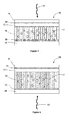
- a dye-sensitized photovoltaic cell 10 comprises a first substrate 16 made of a polymeric material.
- the substrate 16 is flexible.
- the substrate is made of an imide-based or ester-based polymeric material.
- the first substrate is made of a material selected from the group consisting of: polycarbonate (PC), polyethylene terephthalate (PET), polyether sulfones (PES), polyimide and polytetrafluoroethylene (PTFE) . Selection of the most suitable material may depend on a plurality of factors, including the ability of withstanding the relatively high temperatures of photovoltaic cell manufacturing processes and/or the transparency to incident light.
- PET transparent
- PC transparent
- the substrate is made of polyimide.
- the first substrate consists of a Kapton® HN film, manufactured by DuPontTM, which withstands relatively high temperatures, e.g. to about 400°C.
- the substrate may be made of 6FDA-DAD polyimide, composed of the following monomers: 4,4'-hexafluoroisopropylene phthalic anhydride and 2,3,5,6 tetramethyl-p-phenylene diamine.
- 6FDA-DAD polyimide composed of the following monomers: 4,4'-hexafluoroisopropylene phthalic anhydride and 2,3,5,6 tetramethyl-p-phenylene diamine.
- Such polyimide withstands temperatures above 350°C and is transparent to visible and near-infrared light.
- the first substrate 16 has a top surface, with a titanium metal layer 15 arranged thereon.
- the titanium layer 15 contacts the top surface of the first substrate and forms the anode of the photovoltaic cell 10.
- the thickness of the titanium metal layer that forms the anode preferably ranges from 50 to 200 nm.
- a nanostructure 14 is formed on the titanium layer 15, preferably in direct contact therewith, and comprises a titanium dioxide (TiO 2 ) nanotube array.
- the nanotubes are formed by an anodization process.
- the nanostructure 14 essentially consists of a nanotube array.
- nanotubes are formed by an anodization process, they have an approximately cylindrical hollow shape, closed at the bottom.
- the closed base of nanotubes, which defines the bottom surface of the nanostructure contacts the underlying titanium layer 15.
- the nanotube array may have a closely packed hexagonal geometry, or a square geometry.
- the main dimensional parameters that characterize nanotubes are length, internal radius, external radius and wall thickness, derived from the latter two parameters.
- the nanotubes have a crystalline structure.
- the structure consisting of a titanium metal layer (unoxidized) with a nanotube array arranged thereon may be formed by deposition of a Ti primary layer directly on the first substrate, followed by an anodization process, in which anodization is not performed throughout the thickness of the Ti primary layer, as explained in greater detail below. It will be appreciated that the presence of a Ti metal layer avoids the need for a conductive layer between the first polymeric substrate 16 and the nanostructure 14, as electric conduction during operation of the photovoltaic cell is ensured by the Ti layer itself, which acts as an anode.
- the TiO 2 nanotube array at least partially contacts a photosensitive, light-absorbing material 17.
- the photosensitive material comprises an organic dye, which consists of a photosensitizer molecular complex, e.g. a ruthenium complex.
- a photosensitizer molecular complex e.g. a ruthenium complex.
- a conductive transparent layer 12 is arranged on the nanostructure 14 to form the cathode of the photovoltaic cell.
- the conductive layer 12 is made of a transparent conductive oxide (TCO), e.g. ITO (indium-tin oxide) or FTO (fluorine doped tin oxide).
- TCO transparent conductive oxide
- ITO indium-tin oxide
- FTO fluorine doped tin oxide
- a second substrate 11, transparent to light, is arranged on the conductive transparent layer 12.
- the second substrate is a flexible substrate made of a transparent polymeric material, e.g. PET.
- the gap between the anode 15 and the cathode 12 is filled with a redox electrolyte 13.
- the redox electrolyte includes a redox couple in a liquid solution or in gel form. In practice, the electrolyte is dispersed between the nanotubes and has the purpose of reducing the molecules after electron injection into TiO 2 .
- the nanostructure, the photosensitive dye and the redox electrolyte form the active photovoltaic layer of the photovoltaic cell.
- the Ti layer 15 that acts as an anode is not particularly suitable for direct light radiation, as the latter would cause reflections of a significant portion of the incident light.
- the photovoltaic cell 10 of Figure 1 is oriented, in operation, such that light impinges upon the side with the cathode of transparent material 12, whereas the first substrate 16 and the anode 15 form the unlighted back side of the cell.
- the second substrate 11 against which direct light radiation impinges, is made of a transparent material.
- the incident light designated by arrow 18, passes through the second substrate 11 and the conductive layer 12 and hits the dye molecules, that form the photosensitive material 17 of the cell.
- the dye molecules absorb the photons and reach a photoexcited state, in which pairs of free charge carrier pairs, i.e. electron-hole pairs, are generated.
- the free charge carrier pairs are separated at the interface between the photosensitive material and the TiO 2 nanotubes and, for each pair, an electron is directly "injected" into the conduction band of TiO 2 , to be carried to the anode, i.e. the unoxidized titanium layer 15.
- the dye molecule that has lost the electron, is in an oxidized state that can be neutralized by the molecule of the redox couple in the redox electrolyte 13. Therefore, dye molecules are regenerated by redox couples to reduce oxidation thereof.
- the redox electrolyte comprises a liquid electrolytic solution consisting of an organic solvent and a redox couple such as I 3 - /I - .
- the dye molecule that has lost one electron acquires one electron from iodide thereby oxidizing it into a triiodide (I 3 - ).
- FIG. 1 shows a photovoltaic cell of a further embodiment of the present invention.
- Reference numerals like those of Figure 1 designate equal elements or element having the same functions as those described with reference to Figure 1 .
- the first substrate 24 of polymeric material which is preferably flexible, has a conductive layer 21 arranged thereon, to form the anode of the cell.
- the first substrate is made of a transparent material that withstands the crystallization temperatures of the nanotube array.
- the polymeric material of the first substrate is transparent polyimide.
- the first substrate is a colorless (transparent) Kapton® polyimide film, which is being developed by DuPontTM for CdTe-based solar cells.
- the first substrate is made of transparent polyimide 6FDA-DAD.
- the conductive layer 21 is a conductive transparent layer, more preferably a TCO film.
- a nanostructure 22 comprising a titanium dioxide nanotube array is formed on the anode 21.
- the nanostructure 22 directly contacts the conductive layer 21.
- the nanotubes are formed by an anodization process.
- the nanostructure is arranged in contact with the conductive layer by means of a bottom surface.
- the nanostructure 22 essentially consists of a nanotube array, and the nanotube array contacts the conductive layer.
- the nanotube array may have a closely packed hexagonal geometry, or a square geometry.
- the nanotubes Preferably, the nanotubes have a crystalline structure.
- the photovoltaic cell configuration of this embodiment may be obtained by deposition of a Ti layer on the conductive layer that forms the anode, and then by an oxidation process by anodization, in which anodization is performed throughout the thickness of the deposited Ti layer. In other words, the titanium primary layer undergoes a substantially complete anodization.
- the conductive layer 21 has a sheet resistance ranging from 8 to 20 ⁇ /.
- the active photovoltaic layer comprises the nanostructure 22, the photosensitive material 17 and a redox electrolyte 13.
- a further conductive layer 12 and a second substrate of polymeric material, such as PET or PC are arranged on the nanotube array 22.
- the photovoltaic cell of figure 2 When the photovoltaic cell of figure 2 is formed with a first polymeric substrate 24 transparent to incident light, it can be backlit with incident light impinging on the first substrate 24.
- the arrow 23 designates the incident light.
- This operating configuration may be advantageous, in certain embodiments, because light radiation is directly absorbed by the sensitizing molecule without passing through the redox electrolyte, which is often not wholly transparent and hence causes partial light absorption and reduced photoconversion efficiency.
- a Ti metal layer is placed between the conductive transparent layer 21 that forms the anode and the nanostructure 22.
- light incidence occurs in a configuration like that described with reference to Figure 1 .
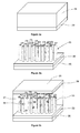
- FIGs 3a-3c schematically and show a sequence of steps of a photovoltaic cell manufacturing process according to one embodiment of the present invention.
- the above process is suitable for manufacturing the photovoltaic cell of Figure 1 .
- a titanium primary layer 31 is deposited on a first substrate 30 of polymeric material, such as a film of polyimide or another plastic material having a high glass transition temperature (e.g. higher than about 300°C-350°C).
- the titanium layer is deposited by sputtering, e.g. magnetron sputtering.
- the deposited titanium layer has a thickness that ranges from 1 ⁇ m to 15 ⁇ m.
- the titanium layer undergoes an anodic oxidation process, also referred in the present descriptione and claims to as anodization, for forming a TiO 2 nanotube array.
- the anodization process involves dipping the Ti primary layer deposited on the first substrate into an electrolytic bath.
- the electrolytic bath comprises an organic solvent and a complexing agent containing fluoride ions.
- the electrolytic bath is contained in a two-electrode electrochemical cell, in which the first electrode is the titanium primary layer and the second layer is a metal sheet, e.g. made of Pt. A voltage is applied between the electrodes.
- nanotubes results from a competition between the electrochemical oxidation of titanium at the free surface of the primary layer and the chemical dissolution of the layer by the fluoride ions in the electrolyte.
- the anodization of the primary layer is not complete and a titanium residual layer that has not reacted with the electrolyte remains at the end of the process.
- the nanotube array does not extend throughout the Ti primary layer, a Ti residual layer remaining underneath the nanotube array.
- Figure 3b shows the structure after the anodization step.
- a nanostructure 33 comprising a nanotube array is arranged on and in contact with a titanium residual layer 32.
- the nanostructure 33 essentially consists of a nanotube array.
- the Ti residual layer 32 is arranged on and in contact with the first substrate 30 of polymeric material and forms the anode of the solar cell.
- the thickness of the Ti residual layer ranges from 50 nm to 200 nm.
- the titanium residual layer may also act as a charge carrier, during anodization, to allow anodization of titanium on an insulating polymeric substrate. Partial anodization through the thickness of the primary layer may be obtained by appropriately selecting the anodization time and turning off the voltage/current generator when, possibly depending on the thickness of the primary layer, the desired thickness of the residual layer has been reached.
- the polymeric material of the first substrate is an electrically insulating material.
- the organic solvent of the electrolytic bath comprises glycerol.
- an electrolytic bath containing an organic solvent and fluoride ions may be preferred to an electrolytic bath consisting of an aqueous solution containing hydrofluoric acid.
- the anodization process is slower in the case of electrolytes containing an organic solvent. Nevertheless, the possible drawback associated with a lower speed of nanotube formation is balanced by the possibility of forming longer nanotubes, due to the less aggressive action of the organic solvent, such as glycerol.
- the top surface of the primary layer i.e. the free surface
- a thin protective layer of alcohol-based ink e.g. by coating the surface of the Ti primary layer with an alcohol ink-based marker pen.
- a protective layer of alcohol-based ink induces the formation of nanotubes having substantially smooth surfaces, and inhibits the formation of scales and residues, which are generally found in nanotube arrays resulting from anodization processes conducted with no protective cover.
- Coating of the titanium surface provides a nanotube array with very clean surfaces, that require no cleaning treatment, such as ultrasonic cleaning, after nanotube growth.
- ink is supposed to allow alcohol contact with titanium during the anodization process, when the sample is dipped in the electrolytic bath. In this way, during the process, alcohol exerts a solvent effect that causes removal of weekly adhered residues from nanotube surfaces.
- the protective layer has a thickness that ranges from 200 nm to 1 ⁇ m.
- Figure 4 is an image obtained by a Scanning Electron Microscope (SEM) of a nanotube array obtained from the anodization process.
- SEM Scanning Electron Microscope
- the openings of nanotube cavities are visible in Figure 4 , which is a side view.
- the nanotubes are about 2 ⁇ m long.
- Figure 5 is a SEM image of a bottom plan view of the nanotube array of Figure 4 , after separation of the nanotubes from the substrate, in which the nanotubes are shown to be closed at their base.
- the nanotubes are arranged with a substantially vertical orientation relative to the top surface of the first substrate.
- the length, internal and external radius and vertical wall thickness of nanotubes may be set, by appropriately selecting at least one of the parameters that characterize the anodization process, such as the voltage to be applied, current density, anodization time and concentration of the complexing agent that dissolves TiO 2 (e.g., HF or NH 4 F).
- the parameters that characterize the anodization process such as the voltage to be applied, current density, anodization time and concentration of the complexing agent that dissolves TiO 2 (e.g., HF or NH 4 F).
- the nanotubes are 2 to 40 ⁇ m long. Length is intended as the length of nanotube sidewalls.
- the sidewall thickness which is defined as the difference between the external radius and the internal radius, ranges from 5 nm to 25 nm.
- the external radius of nanotubes ranges from 10 nm to 150 nm, more preferably from 20 nm to 40 nm.
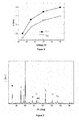
- Figure 6 is a chart that shows the external radius, r ext , (full circles) and the internal radius, r int , (empty circles), as measured on SEM images, of nanotube arrays as a function of the anodization voltage applied during the anodization process, with an electrochemical bath of 0.5-1 wt.% NH 4 F (ammonium fluoride) and 1-5 mol L -1 H 2 O. Anodization was conducted on a 5 ⁇ m Ti primary layer, deposited on polyimide (Kapton® HN). Figure 6 shows that both the external radius and the internal radius increase as the applied voltage increases. By changing the applied voltage, the internal radius may change over a wide range of values, e.g.
- nanotubes having a relatively small external radius, preferably ranging from 20 nm to 40 nm, as the increased specific surface affords a greater load of photosensitive dye.
- the nanotube array obtained from the anodization process has an amorphous structure.
- nanotube crystallization is conducted by heating the nanotube array to a temperature above 200-250°C, e.g. ranging from 300°C to 400°C.
- the heating temperature may be selected according to the polymeric material of which the first substrate is made, and particularly according to the glass transition temperature of such polymeric material.
- the heating process induces crystallization of the nanotubes and of the Ti metal that forms the residual layer.
- the heating process conditions are selected to provide an anatase crystal structure in nanotubes.
- the structure is heated for at least 3 hours, e.g. from 3 to 5 hours, to a temperature of 350°C at ambient atmosphere.
- Figure 7 is an X-ray diffraction pattern (XRD) of a sample that consists of a structure formed of a Kapton® HN substrate, having a titanium primary layer deposited thereon, which is anodized with incomplete anodization, and then heated to 350°C for 5 hours in ambient atmosphere.
- the pattern of Figure 7 which concerns the sample after the heating process, shows diffraction peaks that are designated by symbols, i.e. empty circles and stars.
- Peaks indicated with stars designate the anatase crystal phase of TiO 2 , whereas the empty circles are relative to crystalline titanium metal.
- the titanium metal signal is generated by the Ti residual layer between the polymeric substrate and the nanotube array.
- XRD 2 X-ray diffraction measures taken by a two-dimensional detector, XRD 2 (not shown)
- the Applicant noted that the TiO 2 nanostructure created by anodization of a Ti primary layer directly formed on a polymeric substrate has no preferential direction of the TiO 2 phase. In other words, nanotubes are crystallized with crystalline domains having mutual random orientations.
- the nanostructure is exposed to a photosensitive material which comprises an organic dye, consisting of a photosensitizer molecular complex.
- a photosensitive material which comprises an organic dye, consisting of a photosensitizer molecular complex.
- a transparent conductive layer is arranged on the TiO 2 nanostructure.
- the transparent conductive layer that forms the cathode of the solar cell is preferably formed on a second substrate of transparent material.
- a TCO layer is grown on a substrate of transparent polymeric material, before placing the latter on the nanostructure.
- FIG. 3c shows the structure of the finished solar cell, which comprises the organic dye 36 absorbed by the nanostructure, and a TCO layer 34 arranged on the nanotube array 33.
- the TCO layer is arranged on a second substrate 35, preferably made of a polymeric material, and the second substrate with the TCO layer is arranged on the nanostructure 33.
- the gap between the cathode 34 and the anode 32 is filled with a redox electrolyte 37.
- FIGs 8a-8c sequentially show some steps of a photovoltaic cell manufacturing process according to one embodiment of the present invention.
- the above process is suitable for manufacturing the photovoltaic cell of Figure 2 .
- a transparent conductive layer 41 preferably a TCO layer, is deposited on a substrate 40 of transparent polymeric material, such as a film of transparent polyimide having a glass transition temperature above 300°C.
- the TCO layer may be deposited to obtain a solar cell with a transparent photoanode, after complete anodization of the titanium primary layer 42.
- the thickness of the TCO layer ranges from 50 to 200 nm.
- a titanium primary layer 42 is deposited on the TCO layer 41.
- the titanium layer is deposited by sputtering, e.g. magnetron sputtering.
- the deposited titanium layer has a thickness that ranges from 1 ⁇ m to 15 ⁇ m.
- the titanium layer undergoes an anodization process, for forming a TiO 2 nanotube array.
- the anodization process involves dipping the Ti primary layer deposited on the first substrate into an electrolytic bath.
- anodization of the primary layer is complete and substantially the entire Ti primary layer has reacted with the electrolyte.
- the nanotube array extend throughout the thickness of the Ti primary layer.
- Figure 8b shows the structure after the anodization step: a nanostructure 43 comprising a nanotube array is arranged on and in contact with the transparent conductive layer.
- the nanostructure 43 essentially consists of a nanotube array.
- Complete anodization is achieved, for instance, by appropriately selecting the anodization time.
- the anodization speed shall be preferably monitored, to prevent anodization of the nanotube layer at the end of the complete anodization of the titanium primary layer, and hence to prevent partial nanotube dissolution.
- a second conductive layer 44 which acts as a cathode for the solar cell, is arranged on the nanostructure.
- the second conductive layer 44 preferably transparent, is formed on a second substrate of polymeric material 45, preferably transparent.
- a TCO layer is deposited on a substrate of transparent polymeric material, such as PET.
- the second substrate 45 with the conductive layer 44 thereon, is arranged on the nanostructure.
- the gap between the anode (i.e. the first conductive transparent substrate 41) and the cathode (the second conductive transparent substrate 44) is filled with a redox electrolyte 47.
- a parameter that characterizes the nanotube array is the roughness factor, RF, which is defined as the total surface area available for impregnation with the dye molecule, per unit area of the sample.
- RF the roughness factor
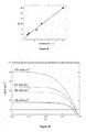
- Figure 9 is a chart that shows the roughness factor (RF) obtained from the analysis of SEM images of a nanotube array having an external radius of 30 nm as a function of the nanotube length. A substantially linear dependence is found between the RF values and nanotube length.
- RF roughness factor
- the roughness factor ranges from 100 nm to 2000, corresponding to a nanotube length range from 2 to 40 nm.
- Roughness factors of less than about 250 were found to ensure an adequate photosensitive dye load on the nanotube array and a sufficient optical density for full absorption of the incident solar radiation in the dye spectral range by the active photovoltaic layer.
- a titanium layer was formed on a substrate consisting of a Kapton®NH sheet, sold by Dupont, by room temperature DC magnetron sputtering.
- the thickness of the substrate was about 250 ⁇ m.
- an argon gas was used at a pressure of 4x10 -3 mbar and a power density of 2.5 W/cm 2 .
- the deposition rate was 1.5 ⁇ m/hour.
- the resulting film showed no crack and was 4 ⁇ m thick. The film did not tend to peel off the substrate upon moderate bending of the first substrate or a heating process to 350°C.
- Titanium layers were anodized at room temperature in an electrochemical cell.
- the Ti layer Prior to anodization, the Ti layer was covered with a thin layer, of about 400 nm, of an ethanol-based ink using an ethanol-based Stabilo OHPen felt-tip pen.
- Anodization was conducted using a power supply ((Delta Elektronika SM 300-5, Netherlands) in a two-electrode cell in potentiostatic conditions, i.e. at constant voltage. A platinum sheet was used as a counter-electrode.
- the electrolytic solution was a glycerol solution of 0.5-1 wt.% NH 4 F (ammonium fluoride) and 1-5 mol L -1 H 2 O.
- the voltage applied between the sample and the Pt cathode was 50 V and the anodization time was about 160 minutes.
- the titanium residual layer was 200 nm thick.
- the nanotubes were 6 ⁇ m long and had an amorphous structure.
- the samples After anodization, the samples underwent a heating process in the ambient atmosphere to 350°C for 5 hours to induce crystallization of amorphous crystals. Then, the samples were washed with distilled water and dried at room temperature.
- the nanotubes were dye-sensitized by 20-hour impregnation in a solution having a 0.5 mM ethanol concentration, and containing a ruthenium-based molecule N719 (manufactured by Solaronix). The unabasorbed dye was removed by ethanol washing. Dye absorption in the structure was quantitatively determined using the US-Vis spectrophotometric method, after a calibration that used diluted aqueous solutions of N719.
- the absorbed dye was completely removed from the top surface of the nanotube structure, i.e. the surface opposite to the first substrate, by washing with an aqueous solution containing 0.1 M NaOH.
- UV-Vis measures were obtained in quartz optical cells, having an optical path of 1 cm, using a double-beam spectrophotometer series T80 by PG Instrument Ltd.
- the solar cell is based on the redox potential of the redox couple I 3 - / I - (triiodide/iodide) using a low-viscosity electrolyte with 50 mM triioide in acetonitrile (Iodolyte AN-50 by Solaronix).
- the active area of the solar cell was 5 ⁇ 5 mm 2 .
- the counter-electrode was a PET sheet covered with a 200 nm TCO layer and having a sheet resistance of 10 ⁇ /. A 5 nm Pt film was deposited on the TCO layer before arranging the counterelectrode on the nanostructure.
- the functional properties of solar cells were investigated by simulating standard insolation conditions (100 mW/cm 2 with an AM1.5G spectrum) using a solar simulator ABET 2000.
- Figure 10 shows experimental current density (j) - voltage (V) curves for different intensities of simulated solar radiation, i.e. 23, 50, 63 and 100 mW/cm 2 .
- Figure 11 is a chart that shows, in the left y-axis, the open-circuit voltage (V oc ) and in the right y-axis the short-circuit current density (j SC ) of the solar cell, as a function of the simulated solar-radiation intensity (experimental values of Figure 10 ).
- the short-circuit current exhibits a linear dependence on incident light intensity, whereas the short-circuit voltage has a sublinear curve, which would be typical for a molecule-sensitized cell.
- Figure 12 is a chart that shows, in the left y-axis, the fill factor (FF) and in the right y-axis the efficiency ( ⁇ ) of the solar cell, as a function of the simulated solar-radiation intensity (experimental data of Figure 10 ). Conversion efficiency was measured and found to be substantially independent of light intensity and equal to about 3.5%.
Landscapes
- Engineering & Computer Science (AREA)
- Power Engineering (AREA)
- Microelectronics & Electronic Packaging (AREA)
- Hybrid Cells (AREA)
Abstract
Description
- The present invention relates to a dye-sensitized photovoltaic cell and a relevant process of manufacturing a dye-sensitized photovoltaic cell. In a particular aspect, the present invention discloses a flexible photovoltaic cell and a process of making it.
- For the last decades, attention has been focused on the investigation of titanium dioxide nanostructures (TiO2), such as TiO2 nanotube arrays, due to their properties, which are relevant in applications such as gas sensors, photovoltaic cells, biomedical materials and photocatalysts.
- TiO2 nanotubes may be manufactured with various methods, including anodic oxidation of titanium films or sheets.
- The paper " Fabrication of TiO2 Nanotubes Thin Films and Their Gas Sensing Properties", by Yonxiang Li et al., Journal of Sensors, vol. 2009 (2009), Paper ID 402174, provides an overview of the manufacturing processes and growth mechanisms of titanium/titania nanotubes, prepared with the anodization proocess.
- Yuxin Tang et al. in "Preparation and Characterization of TiO2 Nanotube Arrays via Anodization of Titanium Films Deposited on FTO Conducting Glass at Room Temperature", Acta Physico-Chimica Sinica, vol. 24(12), pp. 2191-2197, describes TiO2 nanotube arrays prepared on conductive fluorine doped tin oxide (FTO) by electrochemical anodization of pure titanium films deposited by radio frequency magnetron sputtering at room temperature. Nanotubes having a length of 1100 nm and a pore diameter of 75 nm have been prepared by potentiostatic anodization in a 0.5 wt% NH4F/glycerol solution. Dye-sensitized solar cells have raised considerable interest as a possible low-cost alternative to traditional cells.
- G.K. Mor et al. in "A review on highly ordered, vertically oriented TiO2 nanotube arrays: Fabrication, material properties, and solar energy applications", published in Solar Energy and Materials & Solar Cells 90 (2006), pp. 2011-2075, analyse the application of TiO2 nanotube arrays in heterojunction dye-sensitized solar cells. The authors describe the geometry of a solar cell that comprises a nanotube array formed by anodization of a Ti film on a FTO-coated glass.
- O.K. Varghese et al. in "Long vertically aligned titania nanotubes on transparent conducting oxide for highly efficient solar cells", Nature Nanotechnology, vol. 4 (2009), pp. 592-597, note that there are three main challenges in the manufacture of long nanotube array films, which exhibit high optical transparency and superior electric properties, to obtain efficient solar cells: (1) the formation of uniform titanium films with a thickness of tens of micrometers on FTO glass and having enough adhesion to withstand stresses associated with the anodization; (II) the anodization of these thick films until a uniform optical transparency is achieved, and (III) the manufacture of nanotubes using organic nonaqueous fluorine-containing electrolytes, without debris formation or clumping of nanotubes. The authors report the fabrication of transparent titania nanotube films on FTO glass substrates with lengths between 0.3 and 33.0 µm using a novel electrochemistry approach. The authors note that in dye-sensitized solar cells, the active layers consisting of nanoporous TiO2 are as thick as a few tens of micrometers and are in principle suited for flexible applications. Nevertheless, the authors state that typical plastic substrates do not withstand the process temperatures that are typically used for TiO2 nanoparticle sintering. M. Dürr et al. in "Low-temperature fabrication of dye-sensitized solar cells by transfer of composite porous layers", Nature Materials, vol. 4 (2005), pp. 607-611, describe a process of fabrication of dye-sensitized solar cells by transfer of composite porous layers.
- Particularly, a composite porous layer consisting of solid nanoparticles (spherical particles in a first portion of the layer and rodlike particles in a second portion of the layer) is sintered on a glass substrate coated with an Au film and is then removed from the substrate by dissolving the metal layer. Subsequently, the nanoporous layer is transferred to a flexible plastic (i.e. PET) substrate or to a glass substrate. In both cases, the transfer substrate is already coated with a transparent conductive oxide layer (TCO). A thin adhesion layer between the transfer substrate and the porous layer has been deemed to be required for mechanical stability.
- The Applicant has observed that, while the process proposed by M. Dürr and co-authors provides a dye-sensitized solar cell for flexible applications, that process is relatively complex and cannot ensure proper adhesion of the active photovoltaic layer to the substrate.
- The Applicant has realized that a solar cell can be directly fabricated on a substrate of polymeric material, without using relatively complex techniques such as lift-off of the active photovoltaic layer from the original substrate.
- The Applicant has conceived a dye-sensitized photovoltaic cell that can be fabricated on a polymeric substrate using a relatively simple, low-cost process.
- In one aspect, the present invention relates to a dye-sensitized photovoltaic cell, comprising: a first substrate of polymeric material having a top surface; an anode, arranged on the first substrate; an active photovoltaic layer arranged on the anode, and comprising a nanostructure including an array of titanium dioxide nanotubes, a photosensitive material in contact with the nanostructure and a redox electrolyte, and a cathode arranged on the active photovoltaic layer, wherein the redox electrolyte is placed between the anode and the cathode.
- The active photovoltaic layer of the photovoltaic cell comprises the nanostructure, the photosensitive dye and the redox electrolyte.
- Due to their ordered geometry, the nanotubes afford electronic transfer in the cell along much shorter rectilinear paths than in unordered nanocrystalline aggregates, such as an aggregate of solid nanoparticles having a polycrystalline structure. This strongly reduces recombination processes, which might degrade photoconversion efficiency in sensitized solar cells.
- Preferably, the photovoltaic cell further comprises a second substrate of polymeric material and arranged on the cathode. Preferably, the second substrate is made of a transparent polymeric material.
- Preferably, the first substrate is a flexible film of polymeric material.
- Preferably, the second substrate is a flexible film of polymeric material.
- Preferably, the cathode comprises a layer of conductive transparent material.
- Preferably, the first substrate is made of an imide-based or ester-based polymeric material. In certain preferred embodiments, the first substrate is made of polyimide.
- In certain preferred embodiments, the nanostructure essentially consists of a nanotube array. Herein, a nanostructure essentially consisting of a nanotube array is not intended to exclude the presence of TiO2 nanostructures other than nanotubes, in much smaller amounts. Nevertheless, the presence of these structures does not alter the essential nature of the electronic transport towards the anode, which is mainly due to nanotubes.
- In certain preferred embodiments, the nanostructure is obtained by a process of anodization of a titanium primary layer, directly grown on a substrate of polymeric material. In one embodiment, the crystalline structure has crystalline domain with mutual random orientation.
- In certain preferred embodiments, the anode comprises a titanium residual layer which is directly formed on the top surface of the first substrate of polymeric material and the nanostructure including a titanium dioxide nanotube array is arranged on and in contact with the titanium residual layer. Preferably, the anode is made of the titanium residual layer. Preferably, the titanium residual layer has a thickness that ranges from 50 nm to 200 nm.
- Preferably, the nanotube array has a crystalline structure.
- In some embodiments, the photovoltaic cell comprises: a first substrate of polymeric material having a top surface; an anode, arranged on the first substrate; an active photovoltaic layer arranged on the anode, and comprising a nanostructure including an arrangement of titanium dioxide nanotubes, a photosensitive material in contact with the nanostructure and a redox electrolyte, and a cathode arranged on the active photovoltaic layer wherein, in the photovoltaic cell the redox electrolyte is placed between the anode and the cathode, and the anode comprises a first conductive transparent layer. Preferably, in such embodiments, the nanostructure contacts the layer of transparent conductive oxide. In certain embodiments, the anode is made of a transparent conductive layer. Preferably, the first transparent conductive layer has a top surface, and the nanostructure is directly formed on the top surface of the transparent conductive layer. Preferably, the first transparent conductive layer has a sheet resistance ranging from 8 to 20 Ω/.
- Preferably, the nanotube array has a crystalline structure.
- Preferably, the cathode comprises a second conductive layer. Preferably, the first substrate is made of a transparent polymeric material. In certain embodiments, the first substrate is made of polyimide. Preferably, the first substrate is a flexible film of polymeric material. Preferably, the photovoltaic cell further comprises a second substrate of polymeric material and arranged on the cathode. Preferably, the second substrate is made of a transparent polymeric material.
- Preferably, the second substrate is a flexible film of polymeric material.
- In a further aspect, the present invention relates to a process of manufacturing a dye-sensitized photovoltaic cell, which comprises: providing a first substrate of polymeric material having a top surface; forming a titanium primary layer on the first substrate; oxidizing the titanium primary layer to form a nanostructure comprising a titanium dioxide nanotube array, the nanostructure being arranged on a first conductive layer; exposing the nanostructure to contact with a photosensitive material; placing a second conductive layer on the nanostructure, and placing a redox electrolyte between the first and second conductive layers.
- According to certain preferred embodiments, the present invention relates to a process of manufacturing a dye-sensitized photovoltaic cell, which comprises: providing a first substrate of polymeric material having a top surface; forming a titanium primary layer directly on the top surface of the first substrate, where the primary layer has a thickness; incompletely oxidizing the titanium primary layer through the thickness of the primary layer to form a nanostructure comprising a titanium dioxide nanotube array on an unoxidized titanium residual layer, the titanium residual layer being placed between the first substrate and the nanostructure; exposing the nanostructure to contact with a photosensitive material; placing a conductive layer on the nanostructure, and placing a redox electrolyte between the titanium residual layer and the conductive layer.
- In certain embodiments, the titanium primary layer has a thickness that ranges from 1 µm to 15 µm.
- Preferably, placing a redox electrolyte comprises filling the gap between the titanium residual layer and the conductive with a redox electrolyte. In one embodiment, the titanium residual layer acts as an anode for the solar cell and the conductive layer acts as a cathode or counter-electrode.
- Preferably, the step of oxidizing is carried out by an anodization process.
- Preferably, the step of incompletely oxidizing comprises performing anodization through a first thickness portion of the primary layer, having a smaller thickness than the primary layer, and stopping anodization such that a second thickness portion lying under the first portion, remains unoxidized and forms an unoxidized titanium metal residual layer.
- After the formation of the primary layer, the primary layer has a free surface. Preferably, the process also comprises, after depositing the primary layer and prior to oxidizing the primary layer, covering the surface of the primary layer with a protective layer comprising an alcohol-based ink. Preferably, the protective layer has a thickness that ranges from 200 nm to 1000 nm.
- Preferably, the process also comprises, after anodizing the primary layer, crystallizing the nanostructure.
- Preferably, the step of forming a titanium primary layer comprises depositing a titanium primary layer on the top surface of the first substrate of polymeric coating. Preferably, the step of depositing a titanium primary layer is carried out by magnetron sputtering. Preferably, the step of anodizing the primary layer comprises dipping the titanium primary layer deposited on the first substrate into an electrolytic bath which comprises an organic solvent and a complexing agent containing fluoride ions, and providing a potential difference between a first and a second electrode, in which the first electrode comprises the titanium primary layer.
- In certain further embodiments, the present invention relates to a process of manufacturing a dye-sensitized photovoltaic cell, which comprises: providing a first substrate of polymeric material having a top surface; forming a first conductive layer on the top surface of the substrate; forming a titanium primary layer on the first conductive layer, where the primary surface has a thickness; oxidizing the titanium primary layer through the thickness of the primary layer to form a nanostructure comprising a titanium dioxide nanotube array; exposing the nanostructure to contact with a photosensitive material; placing a second conductive layer on the nanostructure, and placing a redox electrolyte between the first conductive layer and the second conductive layer.
- In certain embodiments, the titanium primary layer has a thickness that ranges from 1 µm to 15 µm.
- Preferably, placing a redox electrolyte comprises filling the gap between the first conductive layer and the second conductive layer with a redox electrolyte. In one embodiment, the first conductive layer acts as an anode and the second conductive layer acts as a cathode or counter-electrode.
- Preferably, the step of oxidizing is carried out by an anodization process.
- Preferably, the step of anodizing comprises performing anodization through the thickness of the primary layer such that the nanotube array contacts the top surface of the first conductive layer.
- After the formation of the titanium primary layer, the primary layer has a surface. Preferably, the process also comprises, after depositing the primary layer and prior to oxidizing the primary layer, covering the surface of the primary layer with a protective layer comprising an alcohol-based ink. Preferably, the protective layer has a thickness that ranges from 200 nm to 1000 nm.
- Preferably, the first conductive layer is transparent. Preferably, the first substrate is made of a transparent polymeric material.
- Preferably, the second conductive layer is transparent.
- Further characteristics and advantages of the invention will be apparent from the following detailed description, which is made with reference to non-limiting embodiments thereof, and to the accompanying figures, in which:
-
Figure 1 is a schematic cross sectional view of a photovoltaic cell according to one embodiment of the present invention. -
Figure 2 is a schematic cross sectional view of a photovoltaic cell according to a further embodiment of the present invention. -
Figures 3a-3c sequentially show (in schematic form) some steps of a photovoltaic cell manufacturing process according to one embodiment of the present invention. -
Figure 4 is an image obtained by a Scanning Electron Microscope (SEM) which shows a side view of a nanotube array manufactured according to the present invention. -
Figure 5 is an image obtained by a Scanning Electron Microscope (SEM) which shows a bottom plan view of a nanotube array ofFigure 4 . -
Figure 6 is a chart that shows the exterior radius, rext, (full circles) and the internal radius, rint, (empty circles), as measured from SEM images, of nanotube arrays as a function of the anodization voltage applied during the anodization process. -
Figure 7 is an X-ray diffraction pattern (XRD) of a sample that consists of a structure formed of a Kapton® HN substrate, having a titanium primary layer deposited thereon, which is anodized and then heated to 350°C for 5 hours in the ambient atmosphere. -
Figures 8a-8c sequentially show (in schematic form) some steps of a photovoltaic cell manufacturing process according to one embodiment of the present invention. -
Figure 9 is a chart that shows the roughness factor of TiO2 nanotubes having an exterior radius of 30 nm as a function of their length. -
Figure 10 is a chart that shows experimental current density (j) - voltage (V) curves for different intensities of simulated solar radiation, i.e. 23, 50, 63 and 100 mW/cm2, for a photovoltaic cell formed according to one embodiment of the present invention. -
Figure 11 is a chart that shows, in the left y-axis, the open-circuit voltage (Voc) and in the right y-axis the short-circuit current density (jSC) of the photovoltaic cell ofFigure 10 , as a function of the simulated solar-radiation intensity. -
Figure 12 is a chart that shows, in the left y-axis, the fill factor (FF) and in the right y-axis the efficiency (η) of the photovoltaic cell ofFigure 10 , as a function of the simulated solar-radiation intensity. - Referring to
Figure 1 , a dye-sensitizedphotovoltaic cell 10 comprises afirst substrate 16 made of a polymeric material. Preferably, thesubstrate 16 is flexible. In preferred embodiments, the substrate is made of an imide-based or ester-based polymeric material. In certain embodiments, the first substrate is made of a material selected from the group consisting of: polycarbonate (PC), polyethylene terephthalate (PET), polyether sulfones (PES), polyimide and polytetrafluoroethylene (PTFE) . Selection of the most suitable material may depend on a plurality of factors, including the ability of withstanding the relatively high temperatures of photovoltaic cell manufacturing processes and/or the transparency to incident light. For instance, of the above polymeric materials, PET (transparent) exhibits a glass transition temperature of 70°C, whereas PC (transparent) has a glass transition temperature of 150°C, both values being lower than the temperatures at which nanotube crystallization is induced, as described below in greater detail. - In certain preferred embodiments, the substrate is made of polyimide. For example, the first substrate consists of a Kapton® HN film, manufactured by DuPont™, which withstands relatively high temperatures, e.g. to about 400°C.
- Still by way of example, the substrate may be made of 6FDA-DAD polyimide, composed of the following monomers: 4,4'-hexafluoroisopropylene phthalic anhydride and 2,3,5,6 tetramethyl-p-phenylene diamine. Such polyimide withstands temperatures above 350°C and is transparent to visible and near-infrared light.
- The
first substrate 16 has a top surface, with atitanium metal layer 15 arranged thereon. Thetitanium layer 15 contacts the top surface of the first substrate and forms the anode of thephotovoltaic cell 10. The thickness of the titanium metal layer that forms the anode preferably ranges from 50 to 200 nm. - A
nanostructure 14 is formed on thetitanium layer 15, preferably in direct contact therewith, and comprises a titanium dioxide (TiO2) nanotube array. In the preferred embodiments, the nanotubes are formed by an anodization process. In one embodiment, thenanostructure 14 essentially consists of a nanotube array. - If nanotubes are formed by an anodization process, they have an approximately cylindrical hollow shape, closed at the bottom. The closed base of nanotubes, which defines the bottom surface of the nanostructure contacts the
underlying titanium layer 15. The nanotube array may have a closely packed hexagonal geometry, or a square geometry. The main dimensional parameters that characterize nanotubes are length, internal radius, external radius and wall thickness, derived from the latter two parameters. Preferably, the nanotubes have a crystalline structure. - The structure consisting of a titanium metal layer (unoxidized) with a nanotube array arranged thereon may be formed by deposition of a Ti primary layer directly on the first substrate, followed by an anodization process, in which anodization is not performed throughout the thickness of the Ti primary layer, as explained in greater detail below. It will be appreciated that the presence of a Ti metal layer avoids the need for a conductive layer between the first
polymeric substrate 16 and thenanostructure 14, as electric conduction during operation of the photovoltaic cell is ensured by the Ti layer itself, which acts as an anode. - The TiO2 nanotube array at least partially contacts a photosensitive, light-absorbing
material 17. The photosensitive material comprises an organic dye, which consists of a photosensitizer molecular complex, e.g. a ruthenium complex. In practice, by having the photosensitive material contact the nanostructure, the inner cavities and the outer surfaces of the nanotubes and the interstices between the nanotubes absorb the photosensitive molecules. - A conductive
transparent layer 12 is arranged on thenanostructure 14 to form the cathode of the photovoltaic cell. In certain embodiments, theconductive layer 12 is made of a transparent conductive oxide (TCO), e.g. ITO (indium-tin oxide) or FTO (fluorine doped tin oxide). - Preferably, a
second substrate 11, transparent to light, is arranged on the conductivetransparent layer 12. Preferably, the second substrate is a flexible substrate made of a transparent polymeric material, e.g. PET. - The gap between the
anode 15 and thecathode 12 is filled with aredox electrolyte 13. The redox electrolyte includes a redox couple in a liquid solution or in gel form. In practice, the electrolyte is dispersed between the nanotubes and has the purpose of reducing the molecules after electron injection into TiO2. - The nanostructure, the photosensitive dye and the redox electrolyte form the active photovoltaic layer of the photovoltaic cell.
- The
Ti layer 15 that acts as an anode is not particularly suitable for direct light radiation, as the latter would cause reflections of a significant portion of the incident light. Thephotovoltaic cell 10 ofFigure 1 is oriented, in operation, such that light impinges upon the side with the cathode oftransparent material 12, whereas thefirst substrate 16 and theanode 15 form the unlighted back side of the cell. Thesecond substrate 11 against which direct light radiation impinges, is made of a transparent material. - In the configuration as shown in
Figure 1 , the incident light, designated byarrow 18, passes through thesecond substrate 11 and theconductive layer 12 and hits the dye molecules, that form thephotosensitive material 17 of the cell. The dye molecules absorb the photons and reach a photoexcited state, in which pairs of free charge carrier pairs, i.e. electron-hole pairs, are generated. The free charge carrier pairs are separated at the interface between the photosensitive material and the TiO2 nanotubes and, for each pair, an electron is directly "injected" into the conduction band of TiO2, to be carried to the anode, i.e. theunoxidized titanium layer 15. The dye molecule, that has lost the electron, is in an oxidized state that can be neutralized by the molecule of the redox couple in theredox electrolyte 13. Therefore, dye molecules are regenerated by redox couples to reduce oxidation thereof. For example, the redox electrolyte comprises a liquid electrolytic solution consisting of an organic solvent and a redox couple such as I3 -/I-. The dye molecule that has lost one electron, acquires one electron from iodide thereby oxidizing it into a triiodide (I3 -). - An electric connection external to the cell, not shown in
Figure 1 , between the anode and the cathode, allows connection of the cell to external loads, which may absorb electric power from the cell when the latter is radiated by light in the spectrum absorbed by the sensitizer molecule, e.g. the visible spectrum if the molecular complex is ruthenium-based.Figure 2 shows a photovoltaic cell of a further embodiment of the present invention. Reference numerals like those ofFigure 1 designate equal elements or element having the same functions as those described with reference toFigure 1 . In thephotovoltaic cell 20, thefirst substrate 24 of polymeric material, which is preferably flexible, has aconductive layer 21 arranged thereon, to form the anode of the cell. Preferably, the first substrate is made of a transparent material that withstands the crystallization temperatures of the nanotube array. In certain preferred embodiments, the polymeric material of the first substrate is transparent polyimide. - For instance, the first substrate is a colorless (transparent) Kapton® polyimide film, which is being developed by DuPont™ for CdTe-based solar cells.
- In one embodiment, the first substrate is made of transparent polyimide 6FDA-DAD. Preferably, the
conductive layer 21 is a conductive transparent layer, more preferably a TCO film. - A
nanostructure 22 comprising a titanium dioxide nanotube array is formed on theanode 21. Preferably, thenanostructure 22 directly contacts theconductive layer 21. In the preferred embodiments, the nanotubes are formed by an anodization process. - Preferably, the nanostructure is arranged in contact with the conductive layer by means of a bottom surface.
- In one embodiment, the
nanostructure 22 essentially consists of a nanotube array, and the nanotube array contacts the conductive layer. - The nanotube array may have a closely packed hexagonal geometry, or a square geometry. Preferably, the nanotubes have a crystalline structure. The photovoltaic cell configuration of this embodiment may be obtained by deposition of a Ti layer on the conductive layer that forms the anode, and then by an oxidation process by anodization, in which anodization is performed throughout the thickness of the deposited Ti layer. In other words, the titanium primary layer undergoes a substantially complete anodization.
- Preferably, the
conductive layer 21 has a sheet resistance ranging from 8 to 20 Ω/. - The active photovoltaic layer comprises the
nanostructure 22, thephotosensitive material 17 and aredox electrolyte 13. A furtherconductive layer 12 and a second substrate of polymeric material, such as PET or PC are arranged on thenanotube array 22. - When the photovoltaic cell of
figure 2 is formed with a firstpolymeric substrate 24 transparent to incident light, it can be backlit with incident light impinging on thefirst substrate 24. Thearrow 23 designates the incident light. This operating configuration may be advantageous, in certain embodiments, because light radiation is directly absorbed by the sensitizing molecule without passing through the redox electrolyte, which is often not wholly transparent and hence causes partial light absorption and reduced photoconversion efficiency. - In one embodiment, not shown in the figures, a Ti metal layer is placed between the conductive
transparent layer 21 that forms the anode and thenanostructure 22. In this embodiment, light incidence occurs in a configuration like that described with reference toFigure 1 . -
Figures 3a-3c schematically and show a sequence of steps of a photovoltaic cell manufacturing process according to one embodiment of the present invention. The above process is suitable for manufacturing the photovoltaic cell ofFigure 1 . - Referring to
Figure 3a , a titaniumprimary layer 31 is deposited on afirst substrate 30 of polymeric material, such as a film of polyimide or another plastic material having a high glass transition temperature (e.g. higher than about 300°C-350°C). Preferably, the titanium layer is deposited by sputtering, e.g. magnetron sputtering. In certain embodiments, the deposited titanium layer has a thickness that ranges from 1 µm to 15 µm. - After deposition, the titanium layer undergoes an anodic oxidation process, also referred in the present descriptione and claims to as anodization, for forming a TiO2 nanotube array. The anodization process (not shown) involves dipping the Ti primary layer deposited on the first substrate into an electrolytic bath. In certain embodiments, the electrolytic bath comprises an organic solvent and a complexing agent containing fluoride ions. The electrolytic bath is contained in a two-electrode electrochemical cell, in which the first electrode is the titanium primary layer and the second layer is a metal sheet, e.g. made of Pt. A voltage is applied between the electrodes. The formation of nanotubes results from a competition between the electrochemical oxidation of titanium at the free surface of the primary layer and the chemical dissolution of the layer by the fluoride ions in the electrolyte. In this embodiment, the anodization of the primary layer is not complete and a titanium residual layer that has not reacted with the electrolyte remains at the end of the process. In other words, the nanotube array does not extend throughout the Ti primary layer, a Ti residual layer remaining underneath the nanotube array.
Figure 3b shows the structure after the anodization step. Ananostructure 33 comprising a nanotube array is arranged on and in contact with a titaniumresidual layer 32. Preferably, thenanostructure 33 essentially consists of a nanotube array. The Tiresidual layer 32 is arranged on and in contact with thefirst substrate 30 of polymeric material and forms the anode of the solar cell. Preferably, the thickness of the Ti residual layer ranges from 50 nm to 200 nm. - It shall be appreciated that the titanium residual layer may also act as a charge carrier, during anodization, to allow anodization of titanium on an insulating polymeric substrate. Partial anodization through the thickness of the primary layer may be obtained by appropriately selecting the anodization time and turning off the voltage/current generator when, possibly depending on the thickness of the primary layer, the desired thickness of the residual layer has been reached.
- In the preferred embodiments, the polymeric material of the first substrate is an electrically insulating material.
- In one embodiment, the organic solvent of the electrolytic bath comprises glycerol. In certain embodiments, an electrolytic bath containing an organic solvent and fluoride ions may be preferred to an electrolytic bath consisting of an aqueous solution containing hydrofluoric acid. The anodization process is slower in the case of electrolytes containing an organic solvent. Nevertheless, the possible drawback associated with a lower speed of nanotube formation is balanced by the possibility of forming longer nanotubes, due to the less aggressive action of the organic solvent, such as glycerol.
- Preferably, after deposition of the titanium primary layer and before the anodization process, the top surface of the primary layer, i.e. the free surface, is covered with a thin protective layer of alcohol-based ink, e.g. by coating the surface of the Ti primary layer with an alcohol ink-based marker pen. The Applicant noted that the presence of a protective layer of alcohol-based ink induces the formation of nanotubes having substantially smooth surfaces, and inhibits the formation of scales and residues, which are generally found in nanotube arrays resulting from anodization processes conducted with no protective cover. Coating of the titanium surface provides a nanotube array with very clean surfaces, that require no cleaning treatment, such as ultrasonic cleaning, after nanotube growth. Without being bound by any particular theory or explanation, ink is supposed to allow alcohol contact with titanium during the anodization process, when the sample is dipped in the electrolytic bath. In this way, during the process, alcohol exerts a solvent effect that causes removal of weekly adhered residues from nanotube surfaces.
- Preferably, the protective layer has a thickness that ranges from 200 nm to 1 µm.
-
Figure 4 is an image obtained by a Scanning Electron Microscope (SEM) of a nanotube array obtained from the anodization process. The openings of nanotube cavities are visible inFigure 4 , which is a side view. The nanotubes are about 2 µm long.Figure 5 is a SEM image of a bottom plan view of the nanotube array ofFigure 4 , after separation of the nanotubes from the substrate, in which the nanotubes are shown to be closed at their base. - The nanotubes are arranged with a substantially vertical orientation relative to the top surface of the first substrate.
- After selection of the electrolytic bath, the length, internal and external radius and vertical wall thickness of nanotubes may be set, by appropriately selecting at least one of the parameters that characterize the anodization process, such as the voltage to be applied, current density, anodization time and concentration of the complexing agent that dissolves TiO2 (e.g., HF or NH4F).
- Preferably, the nanotubes are 2 to 40 µm long. Length is intended as the length of nanotube sidewalls.
- Preferably, the sidewall thickness, which is defined as the difference between the external radius and the internal radius, ranges from 5 nm to 25 nm.
- Preferably, the external radius of nanotubes ranges from 10 nm to 150 nm, more preferably from 20 nm to 40 nm.
-
Figure 6 is a chart that shows the external radius, rext, (full circles) and the internal radius, rint, (empty circles), as measured on SEM images, of nanotube arrays as a function of the anodization voltage applied during the anodization process, with an electrochemical bath of 0.5-1 wt.% NH4F (ammonium fluoride) and 1-5 mol L-1 H2O. Anodization was conducted on a 5 µm Ti primary layer, deposited on polyimide (Kapton® HN).Figure 6 shows that both the external radius and the internal radius increase as the applied voltage increases. By changing the applied voltage, the internal radius may change over a wide range of values, e.g. from 10 nm to 150 nm. The lateral thickness of the sidewall slightly increases as the tube radius increases, whereas the specific surface of the nanotube (defined as the surface by unit volume) decreases as the radius increases. In certain embodiments, use is preferably made of nanotubes having a relatively small external radius, preferably ranging from 20 nm to 40 nm, as the increased specific surface affords a greater load of photosensitive dye. - The nanotube array obtained from the anodization process has an amorphous structure. After the anodization process, nanotube crystallization is conducted by heating the nanotube array to a temperature above 200-250°C, e.g. ranging from 300°C to 400°C. The heating temperature may be selected according to the polymeric material of which the first substrate is made, and particularly according to the glass transition temperature of such polymeric material.
- The heating process induces crystallization of the nanotubes and of the Ti metal that forms the residual layer. Preferably, the heating process conditions are selected to provide an anatase crystal structure in nanotubes. For example, the structure is heated for at least 3 hours, e.g. from 3 to 5 hours, to a temperature of 350°C at ambient atmosphere.
-
Figure 7 is an X-ray diffraction pattern (XRD) of a sample that consists of a structure formed of a Kapton® HN substrate, having a titanium primary layer deposited thereon, which is anodized with incomplete anodization, and then heated to 350°C for 5 hours in ambient atmosphere. XRD measurements on the sample, after the anodization process and before the heating process, not shown, exhibit no diffraction peak that might be associated with crystalline TiO2 . The pattern ofFigure 7 , which concerns the sample after the heating process, shows diffraction peaks that are designated by symbols, i.e. empty circles and stars. Peaks indicated with stars designate the anatase crystal phase of TiO2, whereas the empty circles are relative to crystalline titanium metal. The titanium metal signal is generated by the Ti residual layer between the polymeric substrate and the nanotube array. From X-ray diffraction measures taken by a two-dimensional detector, XRD2 (not shown), the Applicant noted that the TiO2 nanostructure created by anodization of a Ti primary layer directly formed on a polymeric substrate has no preferential direction of the TiO2 phase. In other words, nanotubes are crystallized with crystalline domains having mutual random orientations. - After the crystallization step, the nanostructure is exposed to a photosensitive material which comprises an organic dye, consisting of a photosensitizer molecular complex. Such exposition to the photosensitive material, which is absorbed by the nanotube surfaces and by the interstices therebetween, may be obtained by dipping the sample into a solution containing the organic dye, according to well-known methods.
- At a later step, a transparent conductive layer is arranged on the TiO2 nanostructure. The transparent conductive layer that forms the cathode of the solar cell is preferably formed on a second substrate of transparent material. In certain preferred embodiments, a TCO layer is grown on a substrate of transparent polymeric material, before placing the latter on the nanostructure.
- Then, the gap between the TCO layer and the titanium residual layer is filled with a redox electrolyte.
Figure 3c shows the structure of the finished solar cell, which comprises theorganic dye 36 absorbed by the nanostructure, and aTCO layer 34 arranged on thenanotube array 33. In certain embodiments, the TCO layer is arranged on asecond substrate 35, preferably made of a polymeric material, and the second substrate with the TCO layer is arranged on thenanostructure 33. The gap between thecathode 34 and theanode 32 is filled with aredox electrolyte 37. -
Figures 8a-8c sequentially show some steps of a photovoltaic cell manufacturing process according to one embodiment of the present invention. The above process is suitable for manufacturing the photovoltaic cell ofFigure 2 . - Referring to
Figure 8a , a transparentconductive layer 41, preferably a TCO layer, is deposited on asubstrate 40 of transparent polymeric material, such as a film of transparent polyimide having a glass transition temperature above 300°C. The TCO layer may be deposited to obtain a solar cell with a transparent photoanode, after complete anodization of the titaniumprimary layer 42. Preferably, the thickness of the TCO layer ranges from 50 to 200 nm. - A titanium
primary layer 42 is deposited on theTCO layer 41. Preferably, the titanium layer is deposited by sputtering, e.g. magnetron sputtering. In certain embodiments, the deposited titanium layer has a thickness that ranges from 1 µm to 15 µm. - After deposition, the titanium layer undergoes an anodization process, for forming a TiO2 nanotube array. The anodization process involves dipping the Ti primary layer deposited on the first substrate into an electrolytic bath. Preferably, in this embodiment, anodization of the primary layer is complete and substantially the entire Ti primary layer has reacted with the electrolyte. In other words, the nanotube array extend throughout the thickness of the Ti primary layer.
Figure 8b shows the structure after the anodization step: ananostructure 43 comprising a nanotube array is arranged on and in contact with the transparent conductive layer. In certain preferred embodiments, thenanostructure 43 essentially consists of a nanotube array. Complete anodization is achieved, for instance, by appropriately selecting the anodization time. In this case, the anodization speed shall be preferably monitored, to prevent anodization of the nanotube layer at the end of the complete anodization of the titanium primary layer, and hence to prevent partial nanotube dissolution. - The next process steps are similar to those described with reference to
Figure 3c . The structure of the resulting solar cell is shown inFigure 8c . Particularly, after exposure of the nanostructure comprising the nanotube array to a photosensitive material 46 (e.g. organic dye), a secondconductive layer 44, which acts as a cathode for the solar cell, is arranged on the nanostructure. In certain embodiments, the secondconductive layer 44, preferably transparent, is formed on a second substrate ofpolymeric material 45, preferably transparent. Preferably, a TCO layer is deposited on a substrate of transparent polymeric material, such as PET. - The
second substrate 45, with theconductive layer 44 thereon, is arranged on the nanostructure. The gap between the anode (i.e. the first conductive transparent substrate 41) and the cathode (the second conductive transparent substrate 44) is filled with a redox electrolyte 47. - A parameter that characterizes the nanotube array is the roughness factor, RF, which is defined as the total surface area available for impregnation with the dye molecule, per unit area of the sample. In the case of a closely packed hexagonal geometry of the nanotube array, the roughness factor is given by:

- In the case of a square geometry of the nanotube array, the roughness factor is given by:

- In the relations (1) and (2), L is the average length of nanotubes and D=2rext, rext being the average external radius of nanotuubes, is the average diameter of nanotubes.
-
Figure 9 is a chart that shows the roughness factor (RF) obtained from the analysis of SEM images of a nanotube array having an external radius of 30 nm as a function of the nanotube length. A substantially linear dependence is found between the RF values and nanotube length. - Preferably, the roughness factor ranges from 100 nm to 2000, corresponding to a nanotube length range from 2 to 40 nm.
- Roughness factors of less than about 250 were found to ensure an adequate photosensitive dye load on the nanotube array and a sufficient optical density for full absorption of the incident solar radiation in the dye spectral range by the active photovoltaic layer.
- A titanium layer was formed on a substrate consisting of a Kapton®NH sheet, sold by Dupont, by room temperature DC magnetron sputtering. The thickness of the substrate was about 250 µm.
- During deposition, an argon gas was used at a pressure of 4x10⁻³ mbar and a power density of 2.5 W/cm2. The deposition rate was 1.5 µm/hour. The resulting film showed no crack and was 4 µm thick. The film did not tend to peel off the substrate upon moderate bending of the first substrate or a heating process to 350°C.
- Titanium layers were anodized at room temperature in an electrochemical cell.
- Prior to anodization, the Ti layer was covered with a thin layer, of about 400 nm, of an ethanol-based ink using an ethanol-based Stabilo OHPen felt-tip pen. Anodization was conducted using a power supply ((Delta Elektronika SM 300-5, Netherlands) in a two-electrode cell in potentiostatic conditions, i.e. at constant voltage. A platinum sheet was used as a counter-electrode. The electrolytic solution was a glycerol solution of 0.5-1 wt.% NH4F (ammonium fluoride) and 1-5 mol L-1 H2O. The voltage applied between the sample and the Pt cathode was 50 V and the anodization time was about 160 minutes. The titanium residual layer was 200 nm thick.
- The nanotubes were 6 µm long and had an amorphous structure.
- After anodization, the samples underwent a heating process in the ambient atmosphere to 350°C for 5 hours to induce crystallization of amorphous crystals. Then, the samples were washed with distilled water and dried at room temperature.
- The nanotubes were dye-sensitized by 20-hour impregnation in a solution having a 0.5 mM ethanol concentration, and containing a ruthenium-based molecule N719 (manufactured by Solaronix). The unabasorbed dye was removed by ethanol washing. Dye absorption in the structure was quantitatively determined using the US-Vis spectrophotometric method, after a calibration that used diluted aqueous solutions of N719.
- The absorbed dye was completely removed from the top surface of the nanotube structure, i.e. the surface opposite to the first substrate, by washing with an aqueous solution containing 0.1 M NaOH. UV-Vis measures were obtained in quartz optical cells, having an optical path of 1 cm, using a double-beam spectrophotometer series T80 by PG Instrument Ltd.
- The solar cell is based on the redox potential of the redox couple I 3 -/I - (triiodide/iodide) using a low-viscosity electrolyte with 50 mM triioide in acetonitrile (Iodolyte AN-50 by Solaronix). The active area of the solar cell was 5×5 mm2. The counter-electrode was a PET sheet covered with a 200 nm TCO layer and having a sheet resistance of 10 Ω/. A 5 nm Pt film was deposited on the TCO layer before arranging the counterelectrode on the nanostructure.
- The functional properties of solar cells were investigated by simulating standard insolation conditions (100 mW/cm2 with an AM1.5G spectrum) using a solar simulator ABET 2000.
-
Figure 10 shows experimental current density (j) - voltage (V) curves for different intensities of simulated solar radiation, i.e. 23, 50, 63 and 100 mW/cm2. -
Figure 11 is a chart that shows, in the left y-axis, the open-circuit voltage (Voc) and in the right y-axis the short-circuit current density (jSC) of the solar cell, as a function of the simulated solar-radiation intensity (experimental values ofFigure 10 ). The short-circuit current exhibits a linear dependence on incident light intensity, whereas the short-circuit voltage has a sublinear curve, which would be typical for a molecule-sensitized cell. -
Figure 12 is a chart that shows, in the left y-axis, the fill factor (FF) and in the right y-axis the efficiency (η) of the solar cell, as a function of the simulated solar-radiation intensity (experimental data ofFigure 10 ). Conversion efficiency was measured and found to be substantially independent of light intensity and equal to about 3.5%.
Claims (16)
- A dye-sensitized photovoltaic cell, comprising:a first substrate of polymeric material having a top surface;an anode arranged on the first substrate;an active photovoltaic layer arranged on the anode, which comprises a nanostructure including an arrangement of titanium dioxide nanotubes, a photosensitive material in contact with the nanostructure and a redox electrolyte, anda cathode arranged on the active photovoltaic layer, wherein the redox electrolyte is placed between the anode and the cathode.
- The cell of claim 1, further comprising a second substrate arranged on the cathode and made of polymeric material.
- The cell of claim 2, wherein the second substrate is made of transparent polymeric material.
- The cell of any of the preceding claims, wherein the cathode comprises a layer of transparent conductive material.
- The cell of any of the preceding claims, wherein the first substrate is made of an imide-based or ester-based polymeric material.
- The cell of any of the preceding claims, wherein the anode comprises a titanium residual layer which is directly formed on the top surface of the first substrate and the nanostructure including an arrangement of titanium dioxide nanotubes is placed on and in contact with the titanium residual layer.
- The cell of claim 6, wherein the titanium residual layer has a thickness of from 50 nm to 200 nm.
- The cell of any of claims from 1 to 5, wherein the anode comprises a layer of transparent conductive oxide.
- The cell of claim 8, wherein the nanostructure contacts the layer of transparent conductive oxide.
- A process of manufacturing a dye-sensitized photovoltaic cell, which comprises:providing a first substrate of polymeric material having a top surface;forming a titanium primary layer on the first substrate;oxidizing the primary titanium layer to form a nanostructure comprising an arrangement of titanium dioxide nanotubes, the nanostructure being arranged on a first conductive layer;exposing the nanostructure to contact with a photosensitive material;placing a second conductive layer on the nanostructure, andplacing a redox electrolyte between the first conductive layer and the second conductive layer.
- The process of claim 10, in which oxidizing is carried out by an anodic oxidation process.
- The process of claim 10 or 11, wherein the primary layer has a surface, the process further comprising, after depositing the primary layer and prior to oxidizing the primary layer, covering the surface of the primary layer with a protective layer comprising an alcohol-based ink.
- The process of any of claims from 10 to 12, which further comprises, after oxidizing the primary layer and prior to exposing the nanostructure to a photosensitive material, crystallizing the nanostructure.
- A process as claimed in any of claims from 10 to 13, wherein
forming a primary layer comprises forming a titanium primary layer directly on the top surface of the first substrate, where the primary layer has a thickness, and oxidizing comprises partially oxidizing the titanium primary layer through a first thickness portion to form a nanostructure lying on a residual non-oxidized titanium layer that forms the first conductive layer and extends along a second thickness portion lying under the first portion, the nanostructure comprising an arrangement of titanium dioxide nanotubes, and the titanium residual layer being interposed between the first substrate and the nanostructure. - The process of claim 14, wherein forming a titanium primary layer comprises depositing a titanium primary layer on the top surface of the first substrate by sputtering deposition.
- The process of claim 14 or 15, wherein oxidizing is carried out by an anodic oxidation process, which comprises dipping the titanium primary layer deposited on the first substrate into an electrolytic bath which comprises an organic solvent and a complexing agent containing fluoride ions, and providing a potential difference between a first and a second electrode, in which the first electrode is the titanium primary layer.
Applications Claiming Priority (1)
| Application Number | Priority Date | Filing Date | Title |
|---|---|---|---|
| IT001162A ITMI20111162A1 (en) | 2011-06-24 | 2011-06-24 | PHOTOVOLTAIC CELL SENSITIZED BY DYES AND PROCESS OF MANUFACTURE OF A PHOTOVOLTAIC CELL SENSITIZED BY DYES. |
Publications (1)
| Publication Number | Publication Date |
|---|---|
| EP2538422A1 true EP2538422A1 (en) | 2012-12-26 |
Family
ID=44898752
Family Applications (1)
| Application Number | Title | Priority Date | Filing Date |
|---|---|---|---|
| EP12173177A Withdrawn EP2538422A1 (en) | 2011-06-24 | 2012-06-22 | Dye-sensitized solar cell and fabrication process thereof |
Country Status (2)
| Country | Link |
|---|---|
| EP (1) | EP2538422A1 (en) |
| IT (1) | ITMI20111162A1 (en) |
Cited By (1)
| Publication number | Priority date | Publication date | Assignee | Title |
|---|---|---|---|---|
| CN105977033A (en) * | 2016-06-15 | 2016-09-28 | 河南师范大学 | Preparation method for ultra-thin cobalt selenosulphide composite nanoarray with rhombic section |
Citations (3)
| Publication number | Priority date | Publication date | Assignee | Title |
|---|---|---|---|---|
| US20090183994A1 (en) * | 2005-09-09 | 2009-07-23 | University Of Nevada, Reno | Preparation of nano-tubular titania substrate with oxygen vacancies and their use in photo-electrolysis of water |
| US20100269894A1 (en) * | 2009-04-28 | 2010-10-28 | Board Of Regents Of The Nevada System Of Higher Education, On Behalf Of The University Of Nevada | Titanium dioxide nanotubes and their use in photovoltaic devices |
| US20110127167A1 (en) * | 2005-12-13 | 2011-06-02 | University Of Nevada, Reno | Preparation of nano-tubular titania substrates having gold and carbon particles deposited thereon and their use in photo-electrolysis of water |
-
2011
- 2011-06-24 IT IT001162A patent/ITMI20111162A1/en unknown
-
2012
- 2012-06-22 EP EP12173177A patent/EP2538422A1/en not_active Withdrawn
Patent Citations (3)
| Publication number | Priority date | Publication date | Assignee | Title |
|---|---|---|---|---|
| US20090183994A1 (en) * | 2005-09-09 | 2009-07-23 | University Of Nevada, Reno | Preparation of nano-tubular titania substrate with oxygen vacancies and their use in photo-electrolysis of water |
| US20110127167A1 (en) * | 2005-12-13 | 2011-06-02 | University Of Nevada, Reno | Preparation of nano-tubular titania substrates having gold and carbon particles deposited thereon and their use in photo-electrolysis of water |
| US20100269894A1 (en) * | 2009-04-28 | 2010-10-28 | Board Of Regents Of The Nevada System Of Higher Education, On Behalf Of The University Of Nevada | Titanium dioxide nanotubes and their use in photovoltaic devices |
Non-Patent Citations (9)
| Title |
|---|
| A. VOMIERO ET AL: "Flexible dye sensitized solar cells using TiO2 nanotubes", ENERGY & ENVIRONMENTAL SCIENCE, vol. 4, no. 9, 29 June 2011 (2011-06-29), pages 3408, XP055021060, ISSN: 1754-5692, DOI: 10.1039/c0ee00485e * |
| G.K. MOR ET AL.: "A review on highly ordered, vertically oriented Ti02 nanotube arrays: Fabrication, material properties, and solar energy applications", SOLAR ENERGY AND MATERIALS & SOLAR CELLS, vol. 90, 2006, pages 2011 - 2075, XP005506286, DOI: doi:10.1016/j.solmat.2006.04.007 |
| M. DURR ET AL.: "Low-temperature fabrication of dye-sensitized solar cells by transfer of composite porous layers", NATURE MATERIALS, vol. 4, 2005, pages 607 - 611, XP008097384, DOI: doi:10.1038/nmat1433 |
| MOR G K ET AL: "A review on highly ordered, vertically oriented TiO2 nanotube arrays: Fabrication, material properties, and solar energy applications", SOLAR ENERGY MATERIALS AND SOLAR CELLS, ELSEVIER SCIENCE PUBLISHERS, AMSTERDAM, NL, vol. 90, no. 14, 6 September 2006 (2006-09-06), pages 2011 - 2075, XP028002102, ISSN: 0927-0248, [retrieved on 20060906], DOI: 10.1016/J.SOLMAT.2006.04.007 * |
| O.K. VARGHESE ET AL.: "Long vertically aligned titania nanotubes on transparent conducting oxide for highly efficient solar cells", NATURE NANOTECHNOLOGY, vol. 4, 2009, pages 592 - 597, XP055021072, DOI: doi:10.1038/nnano.2009.226 |
| OOMMAN K. VARGHESE ET AL: "Long vertically aligned titania nanotubes on transparent conducting oxide for highly efficient solar cells", NATURE NANOTECHNOLOGY, vol. 4, no. 9, 16 August 2009 (2009-08-16), pages 592 - 597, XP055021072, ISSN: 1748-3387, DOI: 10.1038/nnano.2009.226 * |
| VARDAN GALSTYAN ET AL: "Vertically Aligned TiO2 Nanotubes on Plastic Substrates for Flexible Solar Cells", SMALL, vol. 7, no. 17, 27 July 2011 (2011-07-27), pages 2437 - 2442, XP055021059, DOI: 10.1002/smll.201101356 * |
| YONXIANG LI ET AL.: "Fabrication of Ti02 Nanotubes Thin Films and Their Gas Sensing Properties", JOURNAL OF SENSORS, vol. 2009, 2009 |
| YUXIN TANG ET AL.: "Preparation and Characterization of Ti02 Nanotube Arrays via Anodization of Titanium Films Deposited on FTO Conducting Glass at Room Temperature", ACTA PHYSICO-CHIMICA SINICA, vol. 24, no. 12, pages 2191 - 2197, XP025816004, DOI: doi:10.1016/S1872-1508(08)60082-0 |
Cited By (1)
| Publication number | Priority date | Publication date | Assignee | Title |
|---|---|---|---|---|
| CN105977033A (en) * | 2016-06-15 | 2016-09-28 | 河南师范大学 | Preparation method for ultra-thin cobalt selenosulphide composite nanoarray with rhombic section |
Also Published As
| Publication number | Publication date |
|---|---|
| ITMI20111162A1 (en) | 2012-12-25 |
Similar Documents
| Publication | Publication Date | Title |
|---|---|---|
| Chen et al. | Fabrication and characterization of anodic titanium oxide nanotube arrays of controlled length for highly efficient dye-sensitized solar cells | |
| Jen et al. | High-performance large-scale flexible dye-sensitized solar cells based on anodic TiO2 nanotube arrays | |
| CN101719421B (en) | Light anode and flexile solar battery thereof | |
| Lee et al. | Dye-sensitized solar cells with Pt-and TCO-free counter electrodes | |
| Chen et al. | Fabrication of high performance Pt counter electrodes on conductive plastic substrate for flexible dye-sensitized solar cells | |
| Fu et al. | High-performance plastic platinized counter electrode via photoplatinization technique for flexible dye-sensitized solar cells | |
| JP4032873B2 (en) | LAMINATE, MANUFACTURING METHOD THEREOF, AND PRODUCT USING THE SAME | |
| Mohammadpour et al. | Electron transport, trapping and recombination in anodic TiO2 nanotube arrays | |
| Momeni | Dye-sensitized solar cells based on Cr-doped TiO2 nanotube photoanodes | |
| Liu et al. | Hierarchically structured photoanode with enhanced charge collection and light harvesting abilities for fiber-shaped dye-sensitized solar cells | |
| WO2007100095A1 (en) | Method for producing photoelectrode for dye-sensitized solar cell, photoelectrode for dye-sensitized solar cell, and dye-sensitized solar cell | |
| Chen et al. | Double-wall TiO2 nanotubes for dye-sensitized solar cells: a study of growth mechanism | |
| Cho et al. | Impacts of sputter-deposited platinum thickness on the performance of dye-sensitized solar cells | |
| Wu et al. | Anodic TiO2 nanotube arrays for dye-sensitized solar cells characterized by electrochemical impedance spectroscopy | |
| Wang et al. | Improved performance of dye-sensitized solar cells with patterned fluorine-doped tin oxide electrodes | |
| JP4710251B2 (en) | Method for producing metal oxide film | |
| JP4665426B2 (en) | Dye-sensitized solar cell and method for producing the same | |
| Lei et al. | Fabrication of partially crystalline TiO2 nanotube arrays using 1, 2-propanediol electrolytes and application in dye-sensitized solar cells | |
| JP2004311355A (en) | Manufacturing method of electrode substrate | |
| Iraj et al. | TiO2 nanotube formation by Ti film anodization and their transport properties for dye-sensitized solar cells | |
| KR101706125B1 (en) | Dye-sensitized solar cell and method for preparing the same | |
| JP2004127849A (en) | Carbon electrode and dye-sensitized solar cell having the same | |
| Cheong et al. | Performance evaluation of titanium dioxide based dye-sensitized solar cells under the influence of anodization steps, nanotube length and ionic liquid-free redox electrolyte solvents | |
| Choi et al. | Dye-sensitized solar cells employing doubly or singly open-ended TiO2 nanotube arrays: structural geometry and charge transport | |
| Mincuzzi et al. | Laser-Sintered $\hbox {TiO} _ {2} $ Films for Dye Solar Cell Fabrication: An Electrical, Morphological, and Electron Lifetime Investigation |
Legal Events
| Date | Code | Title | Description |
|---|---|---|---|
| PUAI | Public reference made under article 153(3) epc to a published international application that has entered the european phase |
Free format text: ORIGINAL CODE: 0009012 |
|
| AK | Designated contracting states |
Kind code of ref document: A1 Designated state(s): AL AT BE BG CH CY CZ DE DK EE ES FI FR GB GR HR HU IE IS IT LI LT LU LV MC MK MT NL NO PL PT RO RS SE SI SK SM TR |
|
| AX | Request for extension of the european patent |
Extension state: BA ME |
|
| 17P | Request for examination filed |
Effective date: 20130624 |
|
| RBV | Designated contracting states (corrected) |
Designated state(s): AL AT BE BG CH CY CZ DE DK EE ES FI FR GB GR HR HU IE IS IT LI LT LU LV MC MK MT NL NO PL PT RO RS SE SI SK SM TR |
|
| 17Q | First examination report despatched |
Effective date: 20150928 |
|
| GRAP | Despatch of communication of intention to grant a patent |
Free format text: ORIGINAL CODE: EPIDOSNIGR1 |
|
| INTG | Intention to grant announced |
Effective date: 20160506 |
|
| STAA | Information on the status of an ep patent application or granted ep patent |
Free format text: STATUS: THE APPLICATION IS DEEMED TO BE WITHDRAWN |
|
| 18D | Application deemed to be withdrawn |
Effective date: 20160917 |