EP2538199A2 - Signal processing for inlet debris monitoring system to distinguish particulates - Google Patents
Signal processing for inlet debris monitoring system to distinguish particulates Download PDFInfo
- Publication number
- EP2538199A2 EP2538199A2 EP12172754A EP12172754A EP2538199A2 EP 2538199 A2 EP2538199 A2 EP 2538199A2 EP 12172754 A EP12172754 A EP 12172754A EP 12172754 A EP12172754 A EP 12172754A EP 2538199 A2 EP2538199 A2 EP 2538199A2
- Authority
- EP
- European Patent Office
- Prior art keywords
- signal
- debris
- sensor
- domain
- inlet
- Prior art date
- Legal status (The legal status is an assumption and is not a legal conclusion. Google has not performed a legal analysis and makes no representation as to the accuracy of the status listed.)
- Granted
Links
Images

Classifications
-
- G—PHYSICS
- G01—MEASURING; TESTING
- G01N—INVESTIGATING OR ANALYSING MATERIALS BY DETERMINING THEIR CHEMICAL OR PHYSICAL PROPERTIES
- G01N15/00—Investigating characteristics of particles; Investigating permeability, pore-volume or surface-area of porous materials
- G01N15/02—Investigating particle size or size distribution
- G01N15/0266—Investigating particle size or size distribution with electrical classification
-
- F—MECHANICAL ENGINEERING; LIGHTING; HEATING; WEAPONS; BLASTING
- F01—MACHINES OR ENGINES IN GENERAL; ENGINE PLANTS IN GENERAL; STEAM ENGINES
- F01D—NON-POSITIVE DISPLACEMENT MACHINES OR ENGINES, e.g. STEAM TURBINES
- F01D21/00—Shutting-down of machines or engines, e.g. in emergency; Regulating, controlling, or safety means not otherwise provided for
- F01D21/003—Arrangements for testing or measuring
-
- F—MECHANICAL ENGINEERING; LIGHTING; HEATING; WEAPONS; BLASTING
- F02—COMBUSTION ENGINES; HOT-GAS OR COMBUSTION-PRODUCT ENGINE PLANTS
- F02C—GAS-TURBINE PLANTS; AIR INTAKES FOR JET-PROPULSION PLANTS; CONTROLLING FUEL SUPPLY IN AIR-BREATHING JET-PROPULSION PLANTS
- F02C7/00—Features, components parts, details or accessories, not provided for in, or of interest apart form groups F02C1/00 - F02C6/00; Air intakes for jet-propulsion plants
- F02C7/04—Air intakes for gas-turbine plants or jet-propulsion plants
- F02C7/05—Air intakes for gas-turbine plants or jet-propulsion plants having provisions for obviating the penetration of damaging objects or particles
- F02C7/052—Air intakes for gas-turbine plants or jet-propulsion plants having provisions for obviating the penetration of damaging objects or particles with dust-separation devices
-
- B—PERFORMING OPERATIONS; TRANSPORTING
- B64—AIRCRAFT; AVIATION; COSMONAUTICS
- B64D—EQUIPMENT FOR FITTING IN OR TO AIRCRAFT; FLIGHT SUITS; PARACHUTES; ARRANGEMENT OR MOUNTING OF POWER PLANTS OR PROPULSION TRANSMISSIONS IN AIRCRAFT
- B64D33/00—Arrangement in aircraft of power plant parts or auxiliaries not otherwise provided for
- B64D33/02—Arrangement in aircraft of power plant parts or auxiliaries not otherwise provided for of combustion air intakes
- B64D2033/022—Arrangement in aircraft of power plant parts or auxiliaries not otherwise provided for of combustion air intakes comprising bird or foreign object protections
-
- B—PERFORMING OPERATIONS; TRANSPORTING
- B64—AIRCRAFT; AVIATION; COSMONAUTICS
- B64D—EQUIPMENT FOR FITTING IN OR TO AIRCRAFT; FLIGHT SUITS; PARACHUTES; ARRANGEMENT OR MOUNTING OF POWER PLANTS OR PROPULSION TRANSMISSIONS IN AIRCRAFT
- B64D45/00—Aircraft indicators or protectors not otherwise provided for
- B64D2045/009—Fire detection or protection; Erosion protection, e.g. from airborne particles
-
- G—PHYSICS
- G01—MEASURING; TESTING
- G01N—INVESTIGATING OR ANALYSING MATERIALS BY DETERMINING THEIR CHEMICAL OR PHYSICAL PROPERTIES
- G01N15/00—Investigating characteristics of particles; Investigating permeability, pore-volume or surface-area of porous materials
- G01N2015/0042—Investigating dispersion of solids
- G01N2015/0046—Investigating dispersion of solids in gas, e.g. smoke
Definitions
- the present invention relates generally to signal processing, and more specifically to signal processing for inlet debris monitoring systems for gas turbine engines.
- Aircraft gas turbines may operate in a wide range of environments, including environments wherein environmental air contains debris particulates, such as sand or ice, which can be harmful to turbine components.
- IDMS inlet debris monitoring system
- Conventional IDMSs include electrostatic sensors which inductively sense the passage of charged particles, and produce sensor signals proportional to the magnitude of charge on ingested debris. These sensors can take several forms, such as buttons or rings of conductive material within or surrounding turbine air passages. Signals from these sensors are conventionally digitized and analyzed in the time domain to determine when debris events occur, how long debris events last, and the approximate overall rate of debris flow. Similar debris monitoring systems have conventionally been used to monitor debris both in turbine inlets and outlets.
- the present invention is directed toward a method for operating a debris monitoring system.
- At least one sensor continuously monitors passage of particulates through a gas turbine engine to produce a time-domain sensor signal.
- the time-domain sensor signal is Fourier transformed to produce a frequency domain sensor signal.
- the frequency domain sensor signal is partitioned into bins corresponding to particulate composition categories. At least one feature is identified within each bin, and is used to determine the amount of particulate flow of each particulate composition category.
- the invention provides a signal processing method for an inlet debris monitoring system, the method comprising: retrieving time-domain signals from inlet debris sensors; Fourier transforming the time-domain signals to produce a frequency domain sensor signal; subdividing the frequency domain signal into bins corresponding to different particulate compositions; and analyzing a feature of the frequency domain signal to determine particulate quantity and composition.
- the invention provides an inlet debris monitoring system comprising an inlet debris sensor located at an inlet of a gas turbine engine to produce a sensor signal in response the passage of debris; a filter which removes noise and non-debris components from the sensor signal; a signal analysis module which Fourier transforms the sensor signal, subdivides the sensor signal into bins, and identifies features of the sensor signal in each bin; and a decision module which determines mass flow rate and particulate composition from the features in each bin.
- FIG. 1 is a cross-sectional and block diagram of a debris monitoring system of the present invention.
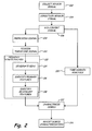
- FIG. 2 is a flow chart depicting steps of a debris monitoring method performed by the debris monitoring system of FIG. 1 .
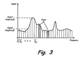
- FIG. 3 is a graph of an example sensor signal as a function of frequency, indicating signal features monitored by the method of FIG. 2 .
- FIG. 1 depicts debris monitoring system 10 for gas turbine engine 12.
- Gas turbine engine 12 is an aircraft gas turbine engine with compressor 14, combustor 16, turbine 18, and inlet 20.
- Debris monitoring system 10 comprises debris sensors 22a and 22b, signal conditioner 24, and signal processor 26, which includes secondary signal conditioner 28, analog/digital converter 30, signal analysis module 34, and decision module 36.
- Gas turbine engine 12 is a conventional gas turbine engine which takes in air via inlet 20, compresses that air at compressor 14, injects fuel into this compressed air and combusts the resulting fuel/air mixture at combustor 16, and extracts energy from the resulting air pressure at turbine 18.
- air flows from left to right through gas turbine engine 12, as shown.
- Debris sensors 22a and 22b produce sensor signals in response to debris passing through inlet 20.
- Signal conditioner 24 receives these sensor signals and conditions them for processing and analog-to-digital conversion.
- Signal processor 26 receives and interprets conditioned sensor signals, producing an output debris characterization which may be stored in a maintenance log, or monitored in an aircraft cockpit.
- Signal processor 26 may, for instance, be an aircraft electronic engine controller or a prognostic health monitoring unit.
- Signal processor 26 may be located on an aircraft carrying gas turbine engine 12, or may be located at a remote location, such as a maintenance facility. If signal processor 26 is located at a remote location, debris monitoring system 10 may include data storage (not shown) for archiving signals for later processing.
- Debris, including small particulates, is sometimes carried by airflow into gas turbine 12. This debris may, for instance, comprise sand, dust, or ice. At least one debris sensor monitors the passage of debris at inlet 20.
- the depicted system includes two such sensors: debris sensor 22a and debris sensor 22b.
- debris sensors 22a and 22b are electrostatic ring sensors which monitor fluctuations in electromagnetic field through the plane of the ring. Thus, charged particulates induce a time-domain signal current by passing through debris sensors 22a and 22b.
- debris sensors 22a and 22b may be other types of sensors, such as electrostatic button sensors.
- debris sensors 22a and 22b cannot detect uncharged debris. Most ingested debris carries at least some electrostatic charge, but any uncharged debris will pass through inlet 20 undetected. In some embodiments debris sensors 22a and 22b are substantially identical. In alternative embodiments, an array of dissimilar sensors may be used.
- Signal conditioner 24 receives signal currents produced by debris sensors 22a and 22b, removes predictable background noise, amplifies resulting signals, and transmits resulting conditioned signals to signal processor 26.
- Signal processor 26 produces a debris characterization from the conditioned signal provided by signal conditioner 24.
- This debris characterization may be stored in a log for retrieval during maintenance of gas turbine engine 12, or forwarded to an aircraft cockpit, or both. In some embodiments the debris characterization will only be stored or forwarded to the cockpit if a debris event is recognized, such a large flow volume of particulates, or an individual discrete large or potentially damaging debris object ingestion.
- the debris characterization includes not only a sensed debris ingestion volume, but a profile of particulate mass flow rate as a function of particulate composition and time. Particulate composition reported in the debris characterization can include both particulate size and material.
- the debris characterization may include a single timestamp associated with an average mass flow rate profile as a function of composition, or may include a plurality of higher resolution time periods
- particulates of different sizes can differently affect each component. For this reason, it is helpful to distinguish between particulate flow rates for different particulate sizes or size ranges. Similarly, particulates of different materials may cause more or less damage, wear, or performance loss of different kinds. Fine particulates, for instance, may pose a greater risk of clogging, while large, hard particulates may cause increased erosion.
- Signal processor 26 includes secondary signal conditioner 28, analog/digital converter 30, signal preprocessor 32, signal analysis module 34, and decision module 36.
- Secondary signal conditioner 28 performs additional signal conditioning to correct signal distortion or corruption between signal conditioner 24 and signal processor 26. Particularly when signal processor 26 is located remotely from signal conditioner 24, predictable noise or distortion can be introduced between signal conditioner 24 and signal processor 26; secondary signal conditioner 28 corrects for these effects.
- Analog/digital converter 30 digitizes the output of secondary signal conditioner 28
- Signal preprocessor 32 performs additional signal filtering on the digitized sensor signal produced by analog/digital converter 30.
- signal conditioner 24 generally conditions sensor signals for analysis by signal processor 26, as described above
- signal preprocessor 32 provides algorithm-specific filtering which conditions sensor signals for particular algorithms used by signal analysis module 34.
- the filter functions applied by signal preprocessor 32 are matched to the algorithms performed by signal analysis module 34, and can be changed if signal analysis module 34 switches algorithms.
- Signal preprocessor 32 can, for instance, apply filters to reduce noise, clean the digital signal to eliminate or reduce statistical outliers, discard data corresponding to outlying frequencies or unexpected voltages, and normalize or down-sample resulting signals.
- Signal analysis module 34 and decision module 36 may comprise separate hardware components of signal processor 26, or may comprise separate software or logical components which run on shared hardware such as a microprocessor.
- Signal analysis module 34 Fourier transforms the sensor signal, subdivides the sensor signal into bins corresponding to particulate composition categories, and identifies features of the sensor signal in each bin.
- the signal output of preprocessor 32 is a time-domain signal with amplitude or energy corresponding to debris ingestion volume.
- Signal analysis module 34 Fourier transforms this time-domain signal to produce a frequency-domain signal.
- Signal analysis module 34 then divides this frequency-domain signal into a plurality of bins. These bins may, for instance, be frequency ranges of the frequency-domain sensor signal, as described with respect to FIG. 3 . Such bins can cover regular, overlapping or non-overlapping ranges, or can cover dynamically updated frequency ranges specified by signal analysis module 34 in response to characteristics of the digitized sensor signal.
- Each bin corresponds to a particle composition range, with higher frequencies generally corresponding to smaller particulates, and lower frequencies corresponding to larger particulates.
- signal analysis module 34 extracts one or more primary signal features such as signal amplitude (maximum or average), signal power, or signal power spectrum slope. These primary signal features correlate with mass flow rate. Increases in signal power or amplitude in a bin over time indicate increases in volume of flow of particulates of the corresponding composition. If bins are not identically sized, sensor signals must be normalized according to bin size to reflect relative flow rates. Wider signal spread (i.e. flatter power spectrum slope) indicates a more sparsely populated bin, and thus a lower flow volume. Some embodiments of analysis module 32 analyze primary signal features to produce secondary signal features such as ratios of power or rates of change between bins. Secondary features are functions of primary features from multiple bins. Secondary features may, for instance, be second-order characteristics derived from primary features.
- signal analysis module 34 processes time-domain sensor signals as well as frequency-domain sensor signals to extract features such as amplitude and peak number.
- time-domain sensor signals are used to recognize ingestion of individual discrete debris objects such as stones or detached bolts.
- frequency-domain signal features time-domain signal features are broken down into a plurality of features which are forwarded to decision module 36.
- Decision module 36 formulates the debris characterization from signal features extracted by signal analysis module 34. Amplitude, power, and power spectrum slope can all be used to estimate flow rate within each bin. In addition to providing a profile of mass flow rate as a function of composition, decision module 36 may also provide a quantitative confidence level indicating the statistical reliability of the debris characterization as a whole, or of each part of the debris characterization.
- some embodiments of debris monitoring system 10 include multiple debris sensors 22a and 22b.
- Signal analysis module 34 can separately extract features, including signal phase, from sensor signals of multiple sensors, just as described above with respect to a single sensor signal. Multiple sensors provide greater data volume, improving the resolution and confidence levels of the debris characterization. Additionally, some embodiments of signal analysis module 34 extract features reflecting relationships between multiple signals. Signal analysis module 34 may, for instance, determine particulate velocities by comparing time- or frequency-domain signals from debris sensors separated by a known distance. Particulate velocity generally diminishes with particulate size, and therefore provides a separate indication of particulate composition, which can be used by decision module 36 in addition to the feature characterization described above.
- Debris monitoring system 10 produces more data at higher precision than purely time-domain based systems by analyzing both frequency- and time-domain signals.
- the addition of multiple debris sensors 22a and 22b further improves the quality and quantity of information produced by debris monitoring system 10.
- FIG. 2 depicts steps of method 100 performed by debris monitoring system 10.
- debris sensors 22a and 22b continuously monitor debris passage to collect at least one sensor signal, as described above.
- Signal conditioner 24 and secondary signal conditioner 28 condition this sensor signal as described with respect to FIG. 1 , filtering and amplifying it as needed.
- Analog/digital converter 30 translates the result into a digital signal.
- Signal preprocessor 32 applies additional filter functions dependent on the features to be extracted from the sensor signal by signal analysis module 34, as described above. (Steps 108).
- time-domain and frequency-domain sensor signals are both analyzed by signal analysis module 34.
- Signal analysis module 34 Fourier transforms the digitized sensor signal (Step 110), and analyzes the resulting frequency-domain sensor signal to produce the debris characterization. (Step 112).
- the frequency-domain sensor signal is subdivided into a plurality of frequency range bins, which may be of fixed or variable width.
- signal analysis module 34 extracts a plurality of primary features, including signal amplitude, signal power, and signal power spectrum slope.
- Signal analysis module 34 next produces a series of secondary features, which reflect second-order properties derived from the primary features, such as energy ratios or rates or change.
- Secondary features may, for instance, include ratios of power or rates of change of primary features in different bins, or relationships between different primary features, such as amplitude and power.
- signal analysis module 34 also analyzes time-domain sensor signals, as known in the prior art. (Step 120). To this end, signal analysis module 34 receives time domain-signals from signal preprocessor 32, and processes these signals to produces time-domain signal features such as the times and amplitudes of peaks corresponding to discrete debris ingestion events. Signal preprocessor 32 may filter signals for time-domain analysis, but the filter function applied for time-domain and frequency-domain preprocessing may differ. In some embodiments, signal analysis module 34 also determines debris velocities from either time- or frequency-domain signals.
- Step 120 This debris characterization includes both times and average particulate flow profiles communicating mass flow rate as a function of particulate composition.
- the time resolution of the reported debris characterization can vary depending on the applications for which the debris characterization is to be used.
- the debris characterization includes an average profile of mass flow as a function of particulate composition, coupled with a timestamps reflecting the period covered by the characterization.
- the debris characterization can include a plurality of such profiles over shorter time intervals.
- Each profile includes, at a minimum, a classification of flow rate for large and small particles.
- each profile may include a measured flow rate across a range of particle compositions categories.
- the debris characterization may also include timestamps and debris characterizations for discrete debris ingestion events determined using methods known in the art.
- FIG. 3 is a graph of an example sensor frequency-domain sensor signal, and is not drawn to scale.
- FIG. 3 shows a plurality of bins B 1 through B N designated by signal analysis module 34. These bins are depicted as having regular widths covering a short frequency range, but may alternatively span irregular frequency ranges. Each bin corresponds to a range of particulate composition, such as range of particulate diameter or mass.
- a variety of primary features may be assigned to each bin, such as signal amplitude or power, as shown. These features may comprise mean or median values within the bin, such as mean amplitude or median power spectrum slope. Each primary feature provides an indication of mass flow rate of particulates of a composition corresponding to the frequency range of the bin.
- the present invention is able to characterize the composition of particulate debris. This characterization allows for more precise maintenance scheduling, reducing maintenance costs and improving aircraft safety. As noted above, prior art time-domain analysis may also be performed to recognize ingestion of individual discrete debris objects. By incorporating multiple debris sensors, the present invention is able to estimate particulate speed (and thereby size), and improve the precision and confidence level of debris characterizations.
Landscapes
- Engineering & Computer Science (AREA)
- Chemical & Material Sciences (AREA)
- Combustion & Propulsion (AREA)
- Mechanical Engineering (AREA)
- General Engineering & Computer Science (AREA)
- Life Sciences & Earth Sciences (AREA)
- Physics & Mathematics (AREA)
- Health & Medical Sciences (AREA)
- Dispersion Chemistry (AREA)
- Analytical Chemistry (AREA)
- Biochemistry (AREA)
- General Health & Medical Sciences (AREA)
- General Physics & Mathematics (AREA)
- Immunology (AREA)
- Pathology (AREA)
- Investigating Or Analyzing Materials By The Use Of Electric Means (AREA)
- Testing And Monitoring For Control Systems (AREA)
- Testing Of Devices, Machine Parts, Or Other Structures Thereof (AREA)
Abstract
Description
- The present invention relates generally to signal processing, and more specifically to signal processing for inlet debris monitoring systems for gas turbine engines.
- Gas turbine engines draw in and compress environmental air. Aircraft gas turbines may operate in a wide range of environments, including environments wherein environmental air contains debris particulates, such as sand or ice, which can be harmful to turbine components.
- Gas turbine engines for aircraft commonly include an inlet debris monitoring system (IDMS) which monitors ingestion of charge-carrying debris, and notifies pilots or updates a maintenance log in the event of discrete debris ingestion. Conventional IDMSs include electrostatic sensors which inductively sense the passage of charged particles, and produce sensor signals proportional to the magnitude of charge on ingested debris. These sensors can take several forms, such as buttons or rings of conductive material within or surrounding turbine air passages. Signals from these sensors are conventionally digitized and analyzed in the time domain to determine when debris events occur, how long debris events last, and the approximate overall rate of debris flow. Similar debris monitoring systems have conventionally been used to monitor debris both in turbine inlets and outlets. Conventional signal processing techniques are not capable of characterizing flow of small particulates which cannot be discretely sensed. While discrete debris ingestion produces relatively sharp time-domain signal peaks corresponding to each ingested debris piece, flow of smaller particulates such as sand or dust produces a broad band debris sensor signal. Conventional signal analysis systems and methods cannot reliably characterize the flow rate and composition of ingested particulate material, including for the purposes of damage estimation and prognosis.
- According to a first aspect, the present invention is directed toward a method for operating a debris monitoring system. At least one sensor continuously monitors passage of particulates through a gas turbine engine to produce a time-domain sensor signal. The time-domain sensor signal is Fourier transformed to produce a frequency domain sensor signal. The frequency domain sensor signal is partitioned into bins corresponding to particulate composition categories. At least one feature is identified within each bin, and is used to determine the amount of particulate flow of each particulate composition category.
According to a second aspect, the invention provides a signal processing method for an inlet debris monitoring system, the method comprising: retrieving time-domain signals from inlet debris sensors; Fourier transforming the time-domain signals to produce a frequency domain sensor signal; subdividing the frequency domain signal into bins corresponding to different particulate compositions; and analyzing a feature of the frequency domain signal to determine particulate quantity and composition.
According to a third aspect, the invention provides an inlet debris monitoring system comprising an inlet debris sensor located at an inlet of a gas turbine engine to produce a sensor signal in response the passage of debris; a filter which removes noise and non-debris components from the sensor signal; a signal analysis module which Fourier transforms the sensor signal, subdivides the sensor signal into bins, and identifies features of the sensor signal in each bin; and a decision module which determines mass flow rate and particulate composition from the features in each bin. -
FIG. 1 is a cross-sectional and block diagram of a debris monitoring system of the present invention. -
FIG. 2 is a flow chart depicting steps of a debris monitoring method performed by the debris monitoring system ofFIG. 1 . -
FIG. 3 is a graph of an example sensor signal as a function of frequency, indicating signal features monitored by the method ofFIG. 2 . -
FIG. 1 depictsdebris monitoring system 10 forgas turbine engine 12.Gas turbine engine 12 is an aircraft gas turbine engine withcompressor 14,combustor 16,turbine 18, andinlet 20.Debris monitoring system 10 comprisesdebris sensors signal conditioner 24, andsignal processor 26, which includessecondary signal conditioner 28, analog/digital converter 30,signal analysis module 34, anddecision module 36. -
Gas turbine engine 12 is a conventional gas turbine engine which takes in air viainlet 20, compresses that air atcompressor 14, injects fuel into this compressed air and combusts the resulting fuel/air mixture atcombustor 16, and extracts energy from the resulting air pressure atturbine 18. InFIG. 1 , air flows from left to right throughgas turbine engine 12, as shown.Debris sensors inlet 20.Signal conditioner 24 receives these sensor signals and conditions them for processing and analog-to-digital conversion.Signal processor 26 receives and interprets conditioned sensor signals, producing an output debris characterization which may be stored in a maintenance log, or monitored in an aircraft cockpit.Signal processor 26 may, for instance, be an aircraft electronic engine controller or a prognostic health monitoring unit.Signal processor 26 may be located on an aircraft carryinggas turbine engine 12, or may be located at a remote location, such as a maintenance facility. Ifsignal processor 26 is located at a remote location,debris monitoring system 10 may include data storage (not shown) for archiving signals for later processing. - Debris, including small particulates, is sometimes carried by airflow into
gas turbine 12. This debris may, for instance, comprise sand, dust, or ice. At least one debris sensor monitors the passage of debris atinlet 20. The depicted system includes two such sensors:debris sensor 22a anddebris sensor 22b. In the depicted embodiment,debris sensors debris sensors embodiments debris sensors debris sensors inlet 20 undetected. In someembodiments debris sensors -
Signal conditioner 24 receives signal currents produced bydebris sensors processor 26.Signal processor 26 produces a debris characterization from the conditioned signal provided bysignal conditioner 24. This debris characterization may be stored in a log for retrieval during maintenance ofgas turbine engine 12, or forwarded to an aircraft cockpit, or both. In some embodiments the debris characterization will only be stored or forwarded to the cockpit if a debris event is recognized, such a large flow volume of particulates, or an individual discrete large or potentially damaging debris object ingestion. The debris characterization includes not only a sensed debris ingestion volume, but a profile of particulate mass flow rate as a function of particulate composition and time. Particulate composition reported in the debris characterization can include both particulate size and material. The debris characterization may include a single timestamp associated with an average mass flow rate profile as a function of composition, or may include a plurality of higher resolution time periods. - Debris of different sizes can differently affect each component. For this reason, it is helpful to distinguish between particulate flow rates for different particulate sizes or size ranges. Similarly, particulates of different materials may cause more or less damage, wear, or performance loss of different kinds. Fine particulates, for instance, may pose a greater risk of clogging, while large, hard particulates may cause increased erosion.
-
Signal processor 26 includessecondary signal conditioner 28, analog/digital converter 30,signal preprocessor 32,signal analysis module 34, anddecision module 36. -
Secondary signal conditioner 28 performs additional signal conditioning to correct signal distortion or corruption betweensignal conditioner 24 andsignal processor 26. Particularly whensignal processor 26 is located remotely fromsignal conditioner 24, predictable noise or distortion can be introduced betweensignal conditioner 24 andsignal processor 26;secondary signal conditioner 28 corrects for these effects. Analog/digital converter 30 digitizes the output ofsecondary signal conditioner 28 -
Signal preprocessor 32 performs additional signal filtering on the digitized sensor signal produced by analog/digital converter 30. In particular, whilesignal conditioner 24 generally conditions sensor signals for analysis bysignal processor 26, as described above,signal preprocessor 32 provides algorithm-specific filtering which conditions sensor signals for particular algorithms used bysignal analysis module 34. The filter functions applied bysignal preprocessor 32 are matched to the algorithms performed bysignal analysis module 34, and can be changed ifsignal analysis module 34 switches algorithms.Signal preprocessor 32 can, for instance, apply filters to reduce noise, clean the digital signal to eliminate or reduce statistical outliers, discard data corresponding to outlying frequencies or unexpected voltages, and normalize or down-sample resulting signals. -
Signal analysis module 34 anddecision module 36 may comprise separate hardware components ofsignal processor 26, or may comprise separate software or logical components which run on shared hardware such as a microprocessor.Signal analysis module 34 Fourier transforms the sensor signal, subdivides the sensor signal into bins corresponding to particulate composition categories, and identifies features of the sensor signal in each bin. - The signal output of
preprocessor 32, like the output ofdebris sensors Signal analysis module 34 Fourier transforms this time-domain signal to produce a frequency-domain signal.Signal analysis module 34 then divides this frequency-domain signal into a plurality of bins. These bins may, for instance, be frequency ranges of the frequency-domain sensor signal, as described with respect toFIG. 3 . Such bins can cover regular, overlapping or non-overlapping ranges, or can cover dynamically updated frequency ranges specified bysignal analysis module 34 in response to characteristics of the digitized sensor signal. Each bin corresponds to a particle composition range, with higher frequencies generally corresponding to smaller particulates, and lower frequencies corresponding to larger particulates. - Within each bin, signal
analysis module 34 extracts one or more primary signal features such as signal amplitude (maximum or average), signal power, or signal power spectrum slope. These primary signal features correlate with mass flow rate. Increases in signal power or amplitude in a bin over time indicate increases in volume of flow of particulates of the corresponding composition. If bins are not identically sized, sensor signals must be normalized according to bin size to reflect relative flow rates. Wider signal spread (i.e. flatter power spectrum slope) indicates a more sparsely populated bin, and thus a lower flow volume. Some embodiments ofanalysis module 32 analyze primary signal features to produce secondary signal features such as ratios of power or rates of change between bins. Secondary features are functions of primary features from multiple bins. Secondary features may, for instance, be second-order characteristics derived from primary features. - Some embodiments of
signal analysis module 34 process time-domain sensor signals as well as frequency-domain sensor signals to extract features such as amplitude and peak number. In particular, time-domain sensor signals are used to recognize ingestion of individual discrete debris objects such as stones or detached bolts. Like frequency-domain signal features, time-domain signal features are broken down into a plurality of features which are forwarded todecision module 36. -
Decision module 36 formulates the debris characterization from signal features extracted bysignal analysis module 34. Amplitude, power, and power spectrum slope can all be used to estimate flow rate within each bin. In addition to providing a profile of mass flow rate as a function of composition,decision module 36 may also provide a quantitative confidence level indicating the statistical reliability of the debris characterization as a whole, or of each part of the debris characterization. - As previously discussed, some embodiments of
debris monitoring system 10 includemultiple debris sensors Signal analysis module 34 can separately extract features, including signal phase, from sensor signals of multiple sensors, just as described above with respect to a single sensor signal. Multiple sensors provide greater data volume, improving the resolution and confidence levels of the debris characterization. Additionally, some embodiments ofsignal analysis module 34 extract features reflecting relationships between multiple signals.Signal analysis module 34 may, for instance, determine particulate velocities by comparing time- or frequency-domain signals from debris sensors separated by a known distance. Particulate velocity generally diminishes with particulate size, and therefore provides a separate indication of particulate composition, which can be used bydecision module 36 in addition to the feature characterization described above. -
Debris monitoring system 10 produces more data at higher precision than purely time-domain based systems by analyzing both frequency- and time-domain signals. The addition ofmultiple debris sensors debris monitoring system 10. -
FIG. 2 depicts steps of method 100 performed bydebris monitoring system 10. First,debris sensors Signal conditioner 24 andsecondary signal conditioner 28 condition this sensor signal as described with respect toFIG. 1 , filtering and amplifying it as needed. (Step 104). Analog/digital converter 30 translates the result into a digital signal. (Step 106).Signal preprocessor 32 applies additional filter functions dependent on the features to be extracted from the sensor signal bysignal analysis module 34, as described above. (Steps 108). - In the depicted embodiment, time-domain and frequency-domain sensor signals are both analyzed by
signal analysis module 34.Signal analysis module 34 Fourier transforms the digitized sensor signal (Step 110), and analyzes the resulting frequency-domain sensor signal to produce the debris characterization. (Step 112). As a first step of this analysis, the frequency-domain sensor signal is subdivided into a plurality of frequency range bins, which may be of fixed or variable width. (Step 114). Within each bin, signalanalysis module 34 extracts a plurality of primary features, including signal amplitude, signal power, and signal power spectrum slope. (Step 116).Signal analysis module 34 next produces a series of secondary features, which reflect second-order properties derived from the primary features, such as energy ratios or rates or change. (Step 118). Secondary features may, for instance, include ratios of power or rates of change of primary features in different bins, or relationships between different primary features, such as amplitude and power. - In the depicted embodiment,
signal analysis module 34 also analyzes time-domain sensor signals, as known in the prior art. (Step 120). To this end,signal analysis module 34 receives time domain-signals fromsignal preprocessor 32, and processes these signals to produces time-domain signal features such as the times and amplitudes of peaks corresponding to discrete debris ingestion events.Signal preprocessor 32 may filter signals for time-domain analysis, but the filter function applied for time-domain and frequency-domain preprocessing may differ. In some embodiments,signal analysis module 34 also determines debris velocities from either time- or frequency-domain signals. -
Decision module 36 characterizes debris according to the primary and secondary features of the frequency-domain signal (Step 118), and reports a debris characterization which in some embodiments includes a quantitative confidence level. (Step 120). This debris characterization includes both times and average particulate flow profiles communicating mass flow rate as a function of particulate composition. The time resolution of the reported debris characterization can vary depending on the applications for which the debris characterization is to be used. At a minimum, the debris characterization includes an average profile of mass flow as a function of particulate composition, coupled with a timestamps reflecting the period covered by the characterization. For greater resolution, the debris characterization can include a plurality of such profiles over shorter time intervals. Each profile includes, at a minimum, a classification of flow rate for large and small particles. For greater precision, each profile may include a measured flow rate across a range of particle compositions categories. The debris characterization may also include timestamps and debris characterizations for discrete debris ingestion events determined using methods known in the art. -
FIG. 3 is a graph of an example sensor frequency-domain sensor signal, and is not drawn to scale.FIG. 3 shows a plurality of bins B1 through BN designated bysignal analysis module 34. These bins are depicted as having regular widths covering a short frequency range, but may alternatively span irregular frequency ranges. Each bin corresponds to a range of particulate composition, such as range of particulate diameter or mass. - A variety of primary features may be assigned to each bin, such as signal amplitude or power, as shown. These features may comprise mean or median values within the bin, such as mean amplitude or median power spectrum slope. Each primary feature provides an indication of mass flow rate of particulates of a composition corresponding to the frequency range of the bin.
- By analyzing debris sensor signals in the frequency domain, the present invention is able to characterize the composition of particulate debris. This characterization allows for more precise maintenance scheduling, reducing maintenance costs and improving aircraft safety. As noted above, prior art time-domain analysis may also be performed to recognize ingestion of individual discrete debris objects. By incorporating multiple debris sensors, the present invention is able to estimate particulate speed (and thereby size), and improve the precision and confidence level of debris characterizations.
- While the invention has been described with reference to an exemplary embodiment(s), it will be understood by those skilled in the art that various changes may be made and equivalents may be substituted for elements thereof without departing from the scope of the invention. In addition, many modifications may be made to adapt a particular situation or material to the teachings of the invention without departing from the essential scope thereof. Therefore, it is intended that the invention not be limited to the particular embodiment(s) disclosed, but that the invention will include all embodiments falling within the scope of the appended claims.
Claims (15)
- A signal processing method for an inlet debris monitoring system (10), the method comprising:retrieving time-domain signals from inlet debris sensors (22a, 22b);Fourier transforming the time-domain signals to produce a frequency domain sensor signal;subdividing the frequency domain signal into bins corresponding to different particulate composition categories; andanalyzing a feature of the frequency domain signal to determine particulate quantity and composition.
- The method of claim 1, wherein the feature of the frequency domain signal comprises amplitude, power, phase or power spectrum rate of change.
- The method of claim 1 or 2, wherein the analyzing is performed on the aircraft; or wherein the analyzing is performed at a location remote from the aircraft.
- The method of claim 1, 2 or 3, wherein the bins comprise frequency ranges of the frequency domain sensor signal; preferably wherein the frequency ranges are dynamically updated.
- The method of claim 1, 2, 3 or 4, wherein the particulate composition determined comprises particulate size.
- The method of any preceding claim, further comprising:preprocessing either the time-domain signals or the frequency-domain sensor signal.
- The method of any preceding claim further comprising:identifying a plurality of time-domain features of the time-domain signal; anddetermining the time and extent of debris events using the time-domain features.
- A method for operating a debris monitoring system, the method comprising:continuously sensing the passage of particulates through a gas turbine engine (12) to produce a time-domain sensor signal; andperforming the signal processing method of any preceding claim, wherein the step of analyzing a feature of the frequency domain signal comprises:identifying a plurality of primary features within each bin; anddetermining the amount of particulate flow in each particulate composition category from the primary features identified within each corresponding bin;preferably wherein the particular composition categories' reflect size of particulates.
- The method of claim 8, further comprising:identifying at least one secondary feature derived from the primary features across multiple bins; andevaluating the determination of particulate flow using the secondary feature.
- The method of claim 8 or 9, wherein continuously sensing the passage of particulates comprises monitoring particulate passage through an inlet (20) of the gas turbine engine (12).
- An inlet debris monitoring system (10) comprising:an inlet debris sensor (22a, 22b) located at an inlet (20) of a gas turbine engine (12) to produce a sensor signal in response the passage of debris;a filter (32) which removes noise and non-debris components from the sensor signal;a signal analysis module (34) which Fourier transforms the sensor signal, subdivides the sensor signal into bins, and identifies features of the sensor signal in each bin; anda decision module (36) which determines mass flow rate and particulate composition from the features in each bin.
- The inlet debris monitoring system of claim 11, wherein the sensor (22a, 22b) is a electrostatic sensor which senses the passage of charged debris particles through a conductive ring; and/or wherein the sensor is an analog sensor, and the system further comprises a signal conditioner (24) and an analog-to-digital converter (30) located between the sensor (22a, 22b) and the signal analysis module (34).
- The inlet debris monitoring system of claim 11 or 12, further comprising at least one additional inlet debris sensor (22a, 22b) located at the inlet (20) of the gas turbine engine (12) to produce an additional sensor signal.
- The inlet debris monitoring system of claim 13, wherein the signal analysis module (34) separately identifies features of the sensor signal and the additional sensor signal, and wherein the decision module (36) evaluates the features of both.
- The inlet debris monitoring system of claim 13 or 14, wherein the signal analysis module (34) identifies features derived from both the sensor signal and the additional sensor signal; preferably wherein one of the features is a particulate speed determined from signal phase differences between the plurality of inlet debris signals.
Applications Claiming Priority (1)
| Application Number | Priority Date | Filing Date | Title |
|---|---|---|---|
| US13/168,293 US8459103B2 (en) | 2011-06-24 | 2011-06-24 | IDMS signal processing to distinguish inlet particulates |
Publications (3)
| Publication Number | Publication Date |
|---|---|
| EP2538199A2 true EP2538199A2 (en) | 2012-12-26 |
| EP2538199A3 EP2538199A3 (en) | 2017-09-13 |
| EP2538199B1 EP2538199B1 (en) | 2018-12-05 |
Family
ID=46851272
Family Applications (1)
| Application Number | Title | Priority Date | Filing Date |
|---|---|---|---|
| EP12172754.9A Active EP2538199B1 (en) | 2011-06-24 | 2012-06-20 | Signal processing for inlet debris monitoring system to distinguish particulates |
Country Status (2)
| Country | Link |
|---|---|
| US (1) | US8459103B2 (en) |
| EP (1) | EP2538199B1 (en) |
Cited By (15)
| Publication number | Priority date | Publication date | Assignee | Title |
|---|---|---|---|---|
| WO2015162160A1 (en) * | 2014-04-24 | 2015-10-29 | Nuovo Pignone Srl | Method of monitoring rubbing between a rotary part and a stationary part in a rotating turbomachine, monitoring arrangement and turbomachine |
| GB2528880A (en) * | 2014-08-01 | 2016-02-10 | Bae Systems Plc | Foreign object debris detection system and method |
| EP3199938A1 (en) * | 2016-01-27 | 2017-08-02 | General Electric Company | Electrostatic dust sensor for an engine |
| EP3199940A1 (en) * | 2016-01-27 | 2017-08-02 | General Electric Company | Electrostatic particle sensor |
| EP3199939A1 (en) * | 2016-01-27 | 2017-08-02 | General Electric Company | Electrostatic dust and debris sensor for an engine |
| US9909971B2 (en) | 2013-09-06 | 2018-03-06 | Ge Aviation Systems Llc | Aircraft and particulate detection method |
| EP3290342A1 (en) * | 2016-09-06 | 2018-03-07 | Rolls-Royce North American Technologies, Inc. | Methods of modifying turbine engine operating limits |
| US9995167B2 (en) | 2014-08-01 | 2018-06-12 | Bae Systems Plc | Turbine blade monitoring |
| US10099804B2 (en) | 2016-06-16 | 2018-10-16 | General Electric Company | Environmental impact assessment system |
| EP3392467A1 (en) * | 2017-04-18 | 2018-10-24 | Honeywell International Inc. | Gas turbine engine particulate ingestion detection system and corresponding method |
| EP3034812B1 (en) * | 2014-12-19 | 2019-10-09 | Rolls-Royce Corporation | Torque sensor monitoring for gas turbine engine |
| CN111024566A (en) * | 2019-10-16 | 2020-04-17 | 重庆邮电大学 | Frequency domain analysis-based mechanical wear degree calibration method and system |
| EP3889395A1 (en) * | 2020-03-30 | 2021-10-06 | Honeywell International Inc. | Gas turbine engine particulate ingestion and accumulation sensor system and method |
| US11149583B2 (en) | 2017-04-18 | 2021-10-19 | Honeywell International Inc. | Gas turbine engine particulate ingestion and accumulation sensor system and method |
| US12331681B2 (en) | 2023-05-09 | 2025-06-17 | Rtx Corporation | Aircraft precipitation monitoring system |
Families Citing this family (18)
| Publication number | Priority date | Publication date | Assignee | Title |
|---|---|---|---|---|
| US9010198B2 (en) * | 2011-07-29 | 2015-04-21 | United Technologies Corporation | Aircraft debris monitoring sensor assembly |
| US8869603B2 (en) * | 2012-02-29 | 2014-10-28 | United Technologies Corporation | Debris detection in turbomachinery and gas turbine engines |
| US9840935B2 (en) | 2014-03-31 | 2017-12-12 | United Technologies Corporation | Rotating machinery monitoring system |
| DE112015003585T5 (en) * | 2015-03-19 | 2017-06-08 | Mitsubishi Heavy Industries, Ltd. | Condition monitoring and condition monitoring method for a delivery gas compression system and delivery gas compression system |
| US10221696B2 (en) | 2016-08-18 | 2019-03-05 | General Electric Company | Cooling circuit for a multi-wall blade |
| CN109641221B (en) * | 2016-08-31 | 2021-07-23 | 埃里埃兹制造公司 | Injector Status Sensor System |
| US12343737B2 (en) * | 2016-08-31 | 2025-07-01 | Eriez Manufacturing Co. | Sparger status sensor system |
| US10071820B2 (en) | 2016-09-19 | 2018-09-11 | Pratt & Whitney Canada Corp. | Inclement weather detection for aircraft engines |
| US10012566B2 (en) | 2016-11-14 | 2018-07-03 | United Technologies Corporation | Parametric trending architecture concept and design |
| US10604278B2 (en) * | 2017-04-18 | 2020-03-31 | General Electric Company | Methods and apparatus to monitor health information of a turbine engine |
| US10998958B1 (en) | 2019-11-22 | 2021-05-04 | Raytheon Technologies Corporation | Radio frequency-based repeater in a waveguide system |
| US11277676B2 (en) | 2019-11-22 | 2022-03-15 | Raytheon Technologies Corporation | Radio frequency system sensor interface |
| US10826547B1 (en) | 2019-11-22 | 2020-11-03 | Raytheon Technologies Corporation | Radio frequency waveguide communication in high temperature environments |
| US11726035B2 (en) * | 2020-12-11 | 2023-08-15 | Raytheon Technologies Corporation | Terahertz enhanced foreign object debris discrimination for optical particulate sensor |
| US11555447B1 (en) * | 2021-07-28 | 2023-01-17 | General Electric Company | System and method for inhibiting particulate and foreign object ingress in combustion systems |
| US12585728B2 (en) | 2022-04-22 | 2026-03-24 | Rtx Corporation | Method and apparatus for machine learning based inlet debris monitoring |
| CN115452923B (en) * | 2022-09-19 | 2024-10-15 | 中国科学院半导体研究所 | Flue gas flow pattern identification method and device based on electrostatic sensor |
| US12391393B2 (en) | 2023-07-20 | 2025-08-19 | Rtx Corporation | Aircraft propulsion system with inlet air monitoring system and method |
Family Cites Families (14)
| Publication number | Priority date | Publication date | Assignee | Title |
|---|---|---|---|---|
| GB8707187D0 (en) | 1987-03-25 | 1987-04-29 | Hughes Ltd Stewart | Monitoring of foreign object in engines |
| DE4008637A1 (en) | 1990-03-17 | 1991-09-19 | Stahlecker Gmbh Wilhelm | DISCONNECTING ROLLER FOR A OE-SPINNING DEVICE |
| US5070722A (en) | 1990-09-21 | 1991-12-10 | United Technologies Corporation | Turbine engine debris ingestion monitor |
| GB2322987A (en) | 1997-03-06 | 1998-09-09 | Marconi Gec Ltd | Object detection in turbine influx or efflux |
| US6668655B2 (en) * | 2001-09-27 | 2003-12-30 | Siemens Westinghouse Power Corporation | Acoustic monitoring of foreign objects in combustion turbines during operation |
| US7275415B2 (en) | 2003-12-31 | 2007-10-02 | Honeywell International Inc. | Particulate-based flow sensor |
| US7871237B2 (en) | 2006-07-07 | 2011-01-18 | Siemens Energy, Inc. | Method and apparatus for monitoring particles in a gas turbine working fluid |
| GB2447238B (en) | 2007-03-07 | 2009-11-18 | Rolls Royce Plc | Method for detecting ice ingestion in a gas turbine engine |
| US8424279B2 (en) | 2007-03-28 | 2013-04-23 | United Technologies Corporation | Particle separator and debris control system |
| US20090112519A1 (en) * | 2007-10-31 | 2009-04-30 | United Technologies Corporation | Foreign object/domestic object damage assessment |
| US20100287907A1 (en) * | 2009-05-18 | 2010-11-18 | Agrawal Rajendra K | System and method of estimating a gas turbine engine surge margin |
| US8074498B2 (en) * | 2009-05-18 | 2011-12-13 | United Technologies Corporation | System and method of assessing thermal energy levels of a gas turbine engine component |
| US8256277B2 (en) * | 2009-06-11 | 2012-09-04 | United Technologies Corporation | Gas turbine engine debris monitoring arrangement |
| GB0917319D0 (en) * | 2009-10-05 | 2009-11-18 | Rolls Royce Plc | An apparatus and method of operating a gas turbine engine |
-
2011
- 2011-06-24 US US13/168,293 patent/US8459103B2/en active Active
-
2012
- 2012-06-20 EP EP12172754.9A patent/EP2538199B1/en active Active
Non-Patent Citations (1)
| Title |
|---|
| None |
Cited By (21)
| Publication number | Priority date | Publication date | Assignee | Title |
|---|---|---|---|---|
| US9909971B2 (en) | 2013-09-06 | 2018-03-06 | Ge Aviation Systems Llc | Aircraft and particulate detection method |
| US10161785B2 (en) | 2014-04-24 | 2018-12-25 | Nuovo Pignone Srl | Method of monitoring rubbing between a rotary party and a stationary part in a rotating turbomachine, monitoring arrangement and turbomachine |
| CN106414911A (en) * | 2014-04-24 | 2017-02-15 | 诺沃皮尼奥内股份有限公司 | Method of monitoring rubbing between a rotary part and a stationary part in a rotating turbomachine, monitoring arrangement and turbomachine |
| WO2015162160A1 (en) * | 2014-04-24 | 2015-10-29 | Nuovo Pignone Srl | Method of monitoring rubbing between a rotary part and a stationary part in a rotating turbomachine, monitoring arrangement and turbomachine |
| CN106414911B (en) * | 2014-04-24 | 2019-05-31 | 诺沃皮尼奥内股份有限公司 | Method, monitoring device and turbine for monitoring friction between rotating and stationary parts in a rotating turbine |
| US9995167B2 (en) | 2014-08-01 | 2018-06-12 | Bae Systems Plc | Turbine blade monitoring |
| US9784827B2 (en) | 2014-08-01 | 2017-10-10 | Bae Systems Plc | Foreign object debris detection system and method |
| GB2528880A (en) * | 2014-08-01 | 2016-02-10 | Bae Systems Plc | Foreign object debris detection system and method |
| EP3034812B1 (en) * | 2014-12-19 | 2019-10-09 | Rolls-Royce Corporation | Torque sensor monitoring for gas turbine engine |
| EP3199939A1 (en) * | 2016-01-27 | 2017-08-02 | General Electric Company | Electrostatic dust and debris sensor for an engine |
| EP4001894A1 (en) * | 2016-01-27 | 2022-05-25 | General Electric Company | Electrostatic particle sensor |
| EP3199940A1 (en) * | 2016-01-27 | 2017-08-02 | General Electric Company | Electrostatic particle sensor |
| EP3199938A1 (en) * | 2016-01-27 | 2017-08-02 | General Electric Company | Electrostatic dust sensor for an engine |
| US10099804B2 (en) | 2016-06-16 | 2018-10-16 | General Electric Company | Environmental impact assessment system |
| US10752382B2 (en) | 2016-06-16 | 2020-08-25 | General Electric Company | Environmental impact assessment system |
| EP3290342A1 (en) * | 2016-09-06 | 2018-03-07 | Rolls-Royce North American Technologies, Inc. | Methods of modifying turbine engine operating limits |
| EP3392467A1 (en) * | 2017-04-18 | 2018-10-24 | Honeywell International Inc. | Gas turbine engine particulate ingestion detection system and corresponding method |
| US11149583B2 (en) | 2017-04-18 | 2021-10-19 | Honeywell International Inc. | Gas turbine engine particulate ingestion and accumulation sensor system and method |
| CN111024566A (en) * | 2019-10-16 | 2020-04-17 | 重庆邮电大学 | Frequency domain analysis-based mechanical wear degree calibration method and system |
| EP3889395A1 (en) * | 2020-03-30 | 2021-10-06 | Honeywell International Inc. | Gas turbine engine particulate ingestion and accumulation sensor system and method |
| US12331681B2 (en) | 2023-05-09 | 2025-06-17 | Rtx Corporation | Aircraft precipitation monitoring system |
Also Published As
| Publication number | Publication date |
|---|---|
| EP2538199A3 (en) | 2017-09-13 |
| US8459103B2 (en) | 2013-06-11 |
| EP2538199B1 (en) | 2018-12-05 |
| US20120324987A1 (en) | 2012-12-27 |
Similar Documents
| Publication | Publication Date | Title |
|---|---|---|
| US8459103B2 (en) | IDMS signal processing to distinguish inlet particulates | |
| US9010198B2 (en) | Aircraft debris monitoring sensor assembly | |
| US8256277B2 (en) | Gas turbine engine debris monitoring arrangement | |
| EP2342498B1 (en) | Combustion anomaly detection via wavelet analysis of dynamic sensor signals | |
| US8818683B2 (en) | Method and apparatus for operating a gas turbine engine | |
| EP0843244A1 (en) | Diagnostic trend analysis for aircraft engines | |
| EP3012460B1 (en) | Systems and methods for monitoring surge conditions | |
| CN103558029A (en) | Abnormal engine sound fault on-line diagnostic system and diagnostic method | |
| US7409854B2 (en) | Method and apparatus for determining an operating status of a turbine engine | |
| EP1272736A2 (en) | Turbine engine foreign object damage detection system | |
| CN118258454B (en) | Water flow detection system based on acoustic chromatography section detection | |
| US20180194487A1 (en) | Optical detector for encounter with debris suspension cloud | |
| US20140216159A1 (en) | Method and arrangement for determining and/or monitoring the state of a roller bearing | |
| KR20180032962A (en) | Apparatus and method for diagnosing measuring partial discharge | |
| WO2015189593A1 (en) | Sensing methods and apparatus | |
| CN113281042A (en) | Early fault diagnosis system and method for walking gearbox of combine harvester | |
| CN112505501A (en) | Partial discharge severity grade judging and early warning method based on electroacoustic combination | |
| CN105574312B (en) | method and system for engineering change data analysis | |
| RU2310180C1 (en) | Method of testing gas turbine engines | |
| US7459962B2 (en) | Transient signal detection algorithm using order statistic filters applied to the power spectral estimate | |
| CN117213864A (en) | Intelligent detection method and system for lubricating oil metal chip particles suitable for engine | |
| CN120995356B (en) | A safety early warning method for powder alloy processing equipment | |
| Karkafi | Nonstationary vibration diagnostics of rotating machinery: Application to aeronautic power transmission systems | |
| Spencer et al. | Acoustic emission monitoring of dense medium cyclones | |
| Rosin et al. | Aircraft noise monitoring: noise level shape and spectrum pattern recognition applied to aircraft noise detection |
Legal Events
| Date | Code | Title | Description |
|---|---|---|---|
| PUAI | Public reference made under article 153(3) epc to a published international application that has entered the european phase |
Free format text: ORIGINAL CODE: 0009012 |
|
| AK | Designated contracting states |
Kind code of ref document: A2 Designated state(s): AL AT BE BG CH CY CZ DE DK EE ES FI FR GB GR HR HU IE IS IT LI LT LU LV MC MK MT NL NO PL PT RO RS SE SI SK SM TR |
|
| AX | Request for extension of the european patent |
Extension state: BA ME |
|
| RAP1 | Party data changed (applicant data changed or rights of an application transferred) |
Owner name: UNITED TECHNOLOGIES CORPORATION |
|
| PUAL | Search report despatched |
Free format text: ORIGINAL CODE: 0009013 |
|
| AK | Designated contracting states |
Kind code of ref document: A3 Designated state(s): AL AT BE BG CH CY CZ DE DK EE ES FI FR GB GR HR HU IE IS IT LI LT LU LV MC MK MT NL NO PL PT RO RS SE SI SK SM TR |
|
| AX | Request for extension of the european patent |
Extension state: BA ME |
|
| RIC1 | Information provided on ipc code assigned before grant |
Ipc: F02C 7/04 20060101ALI20170810BHEP Ipc: G01N 15/02 20060101AFI20170810BHEP |
|
| STAA | Information on the status of an ep patent application or granted ep patent |
Free format text: STATUS: REQUEST FOR EXAMINATION WAS MADE |
|
| 17P | Request for examination filed |
Effective date: 20180312 |
|
| RBV | Designated contracting states (corrected) |
Designated state(s): AL AT BE BG CH CY CZ DE DK EE ES FI FR GB GR HR HU IE IS IT LI LT LU LV MC MK MT NL NO PL PT RO RS SE SI SK SM TR |
|
| GRAP | Despatch of communication of intention to grant a patent |
Free format text: ORIGINAL CODE: EPIDOSNIGR1 |
|
| STAA | Information on the status of an ep patent application or granted ep patent |
Free format text: STATUS: GRANT OF PATENT IS INTENDED |
|
| INTG | Intention to grant announced |
Effective date: 20180614 |
|
| GRAS | Grant fee paid |
Free format text: ORIGINAL CODE: EPIDOSNIGR3 |
|
| GRAA | (expected) grant |
Free format text: ORIGINAL CODE: 0009210 |
|
| GRAA | (expected) grant |
Free format text: ORIGINAL CODE: 0009210 |
|
| STAA | Information on the status of an ep patent application or granted ep patent |
Free format text: STATUS: THE PATENT HAS BEEN GRANTED |
|
| AK | Designated contracting states |
Kind code of ref document: B1 Designated state(s): AL AT BE BG CH CY CZ DE DK EE ES FI FR GB GR HR HU IE IS IT LI LT LU LV MC MK MT NL NO PL PT RO RS SE SI SK SM TR |
|
| REG | Reference to a national code |
Ref country code: GB Ref legal event code: FG4D |
|
| REG | Reference to a national code |
Ref country code: CH Ref legal event code: EP |
|
| REG | Reference to a national code |
Ref country code: AT Ref legal event code: REF Ref document number: 1073676 Country of ref document: AT Kind code of ref document: T Effective date: 20181215 |
|
| REG | Reference to a national code |
Ref country code: IE Ref legal event code: FG4D |
|
| REG | Reference to a national code |
Ref country code: DE Ref legal event code: R096 Ref document number: 602012054252 Country of ref document: DE |
|
| REG | Reference to a national code |
Ref country code: NL Ref legal event code: MP Effective date: 20181205 |
|
| REG | Reference to a national code |
Ref country code: AT Ref legal event code: MK05 Ref document number: 1073676 Country of ref document: AT Kind code of ref document: T Effective date: 20181205 |
|
| REG | Reference to a national code |
Ref country code: LT Ref legal event code: MG4D |
|
| PG25 | Lapsed in a contracting state [announced via postgrant information from national office to epo] |
Ref country code: LV Free format text: LAPSE BECAUSE OF FAILURE TO SUBMIT A TRANSLATION OF THE DESCRIPTION OR TO PAY THE FEE WITHIN THE PRESCRIBED TIME-LIMIT Effective date: 20181205 Ref country code: ES Free format text: LAPSE BECAUSE OF FAILURE TO SUBMIT A TRANSLATION OF THE DESCRIPTION OR TO PAY THE FEE WITHIN THE PRESCRIBED TIME-LIMIT Effective date: 20181205 Ref country code: HR Free format text: LAPSE BECAUSE OF FAILURE TO SUBMIT A TRANSLATION OF THE DESCRIPTION OR TO PAY THE FEE WITHIN THE PRESCRIBED TIME-LIMIT Effective date: 20181205 Ref country code: AT Free format text: LAPSE BECAUSE OF FAILURE TO SUBMIT A TRANSLATION OF THE DESCRIPTION OR TO PAY THE FEE WITHIN THE PRESCRIBED TIME-LIMIT Effective date: 20181205 Ref country code: NO Free format text: LAPSE BECAUSE OF FAILURE TO SUBMIT A TRANSLATION OF THE DESCRIPTION OR TO PAY THE FEE WITHIN THE PRESCRIBED TIME-LIMIT Effective date: 20190305 Ref country code: LT Free format text: LAPSE BECAUSE OF FAILURE TO SUBMIT A TRANSLATION OF THE DESCRIPTION OR TO PAY THE FEE WITHIN THE PRESCRIBED TIME-LIMIT Effective date: 20181205 Ref country code: BG Free format text: LAPSE BECAUSE OF FAILURE TO SUBMIT A TRANSLATION OF THE DESCRIPTION OR TO PAY THE FEE WITHIN THE PRESCRIBED TIME-LIMIT Effective date: 20190305 Ref country code: FI Free format text: LAPSE BECAUSE OF FAILURE TO SUBMIT A TRANSLATION OF THE DESCRIPTION OR TO PAY THE FEE WITHIN THE PRESCRIBED TIME-LIMIT Effective date: 20181205 |
|
| PG25 | Lapsed in a contracting state [announced via postgrant information from national office to epo] |
Ref country code: GR Free format text: LAPSE BECAUSE OF FAILURE TO SUBMIT A TRANSLATION OF THE DESCRIPTION OR TO PAY THE FEE WITHIN THE PRESCRIBED TIME-LIMIT Effective date: 20190306 Ref country code: RS Free format text: LAPSE BECAUSE OF FAILURE TO SUBMIT A TRANSLATION OF THE DESCRIPTION OR TO PAY THE FEE WITHIN THE PRESCRIBED TIME-LIMIT Effective date: 20181205 Ref country code: SE Free format text: LAPSE BECAUSE OF FAILURE TO SUBMIT A TRANSLATION OF THE DESCRIPTION OR TO PAY THE FEE WITHIN THE PRESCRIBED TIME-LIMIT Effective date: 20181205 Ref country code: AL Free format text: LAPSE BECAUSE OF FAILURE TO SUBMIT A TRANSLATION OF THE DESCRIPTION OR TO PAY THE FEE WITHIN THE PRESCRIBED TIME-LIMIT Effective date: 20181205 |
|
| PG25 | Lapsed in a contracting state [announced via postgrant information from national office to epo] |
Ref country code: NL Free format text: LAPSE BECAUSE OF FAILURE TO SUBMIT A TRANSLATION OF THE DESCRIPTION OR TO PAY THE FEE WITHIN THE PRESCRIBED TIME-LIMIT Effective date: 20181205 |
|
| PG25 | Lapsed in a contracting state [announced via postgrant information from national office to epo] |
Ref country code: PL Free format text: LAPSE BECAUSE OF FAILURE TO SUBMIT A TRANSLATION OF THE DESCRIPTION OR TO PAY THE FEE WITHIN THE PRESCRIBED TIME-LIMIT Effective date: 20181205 Ref country code: IT Free format text: LAPSE BECAUSE OF FAILURE TO SUBMIT A TRANSLATION OF THE DESCRIPTION OR TO PAY THE FEE WITHIN THE PRESCRIBED TIME-LIMIT Effective date: 20181205 Ref country code: CZ Free format text: LAPSE BECAUSE OF FAILURE TO SUBMIT A TRANSLATION OF THE DESCRIPTION OR TO PAY THE FEE WITHIN THE PRESCRIBED TIME-LIMIT Effective date: 20181205 Ref country code: PT Free format text: LAPSE BECAUSE OF FAILURE TO SUBMIT A TRANSLATION OF THE DESCRIPTION OR TO PAY THE FEE WITHIN THE PRESCRIBED TIME-LIMIT Effective date: 20190405 |
|
| PG25 | Lapsed in a contracting state [announced via postgrant information from national office to epo] |
Ref country code: IS Free format text: LAPSE BECAUSE OF FAILURE TO SUBMIT A TRANSLATION OF THE DESCRIPTION OR TO PAY THE FEE WITHIN THE PRESCRIBED TIME-LIMIT Effective date: 20190405 Ref country code: RO Free format text: LAPSE BECAUSE OF FAILURE TO SUBMIT A TRANSLATION OF THE DESCRIPTION OR TO PAY THE FEE WITHIN THE PRESCRIBED TIME-LIMIT Effective date: 20181205 Ref country code: EE Free format text: LAPSE BECAUSE OF FAILURE TO SUBMIT A TRANSLATION OF THE DESCRIPTION OR TO PAY THE FEE WITHIN THE PRESCRIBED TIME-LIMIT Effective date: 20181205 Ref country code: SM Free format text: LAPSE BECAUSE OF FAILURE TO SUBMIT A TRANSLATION OF THE DESCRIPTION OR TO PAY THE FEE WITHIN THE PRESCRIBED TIME-LIMIT Effective date: 20181205 Ref country code: SK Free format text: LAPSE BECAUSE OF FAILURE TO SUBMIT A TRANSLATION OF THE DESCRIPTION OR TO PAY THE FEE WITHIN THE PRESCRIBED TIME-LIMIT Effective date: 20181205 |
|
| REG | Reference to a national code |
Ref country code: DE Ref legal event code: R097 Ref document number: 602012054252 Country of ref document: DE |
|
| PLBE | No opposition filed within time limit |
Free format text: ORIGINAL CODE: 0009261 |
|
| STAA | Information on the status of an ep patent application or granted ep patent |
Free format text: STATUS: NO OPPOSITION FILED WITHIN TIME LIMIT |
|
| PG25 | Lapsed in a contracting state [announced via postgrant information from national office to epo] |
Ref country code: SI Free format text: LAPSE BECAUSE OF FAILURE TO SUBMIT A TRANSLATION OF THE DESCRIPTION OR TO PAY THE FEE WITHIN THE PRESCRIBED TIME-LIMIT Effective date: 20181205 Ref country code: DK Free format text: LAPSE BECAUSE OF FAILURE TO SUBMIT A TRANSLATION OF THE DESCRIPTION OR TO PAY THE FEE WITHIN THE PRESCRIBED TIME-LIMIT Effective date: 20181205 |
|
| 26N | No opposition filed |
Effective date: 20190906 |
|
| PG25 | Lapsed in a contracting state [announced via postgrant information from national office to epo] |
Ref country code: MC Free format text: LAPSE BECAUSE OF FAILURE TO SUBMIT A TRANSLATION OF THE DESCRIPTION OR TO PAY THE FEE WITHIN THE PRESCRIBED TIME-LIMIT Effective date: 20181205 |
|
| REG | Reference to a national code |
Ref country code: CH Ref legal event code: PL |
|
| REG | Reference to a national code |
Ref country code: BE Ref legal event code: MM Effective date: 20190630 |
|
| PG25 | Lapsed in a contracting state [announced via postgrant information from national office to epo] |
Ref country code: TR Free format text: LAPSE BECAUSE OF FAILURE TO SUBMIT A TRANSLATION OF THE DESCRIPTION OR TO PAY THE FEE WITHIN THE PRESCRIBED TIME-LIMIT Effective date: 20181205 |
|
| PG25 | Lapsed in a contracting state [announced via postgrant information from national office to epo] |
Ref country code: IE Free format text: LAPSE BECAUSE OF NON-PAYMENT OF DUE FEES Effective date: 20190620 |
|
| PG25 | Lapsed in a contracting state [announced via postgrant information from national office to epo] |
Ref country code: LU Free format text: LAPSE BECAUSE OF NON-PAYMENT OF DUE FEES Effective date: 20190620 Ref country code: BE Free format text: LAPSE BECAUSE OF NON-PAYMENT OF DUE FEES Effective date: 20190630 Ref country code: CH Free format text: LAPSE BECAUSE OF NON-PAYMENT OF DUE FEES Effective date: 20190630 Ref country code: LI Free format text: LAPSE BECAUSE OF NON-PAYMENT OF DUE FEES Effective date: 20190630 |
|
| PG25 | Lapsed in a contracting state [announced via postgrant information from national office to epo] |
Ref country code: CY Free format text: LAPSE BECAUSE OF FAILURE TO SUBMIT A TRANSLATION OF THE DESCRIPTION OR TO PAY THE FEE WITHIN THE PRESCRIBED TIME-LIMIT Effective date: 20181205 |
|
| PG25 | Lapsed in a contracting state [announced via postgrant information from national office to epo] |
Ref country code: MT Free format text: LAPSE BECAUSE OF FAILURE TO SUBMIT A TRANSLATION OF THE DESCRIPTION OR TO PAY THE FEE WITHIN THE PRESCRIBED TIME-LIMIT Effective date: 20181205 Ref country code: HU Free format text: LAPSE BECAUSE OF FAILURE TO SUBMIT A TRANSLATION OF THE DESCRIPTION OR TO PAY THE FEE WITHIN THE PRESCRIBED TIME-LIMIT; INVALID AB INITIO Effective date: 20120620 |
|
| PG25 | Lapsed in a contracting state [announced via postgrant information from national office to epo] |
Ref country code: MK Free format text: LAPSE BECAUSE OF FAILURE TO SUBMIT A TRANSLATION OF THE DESCRIPTION OR TO PAY THE FEE WITHIN THE PRESCRIBED TIME-LIMIT Effective date: 20181205 |
|
| REG | Reference to a national code |
Ref country code: DE Ref legal event code: R081 Ref document number: 602012054252 Country of ref document: DE Owner name: RAYTHEON TECHNOLOGIES CORPORATION (N.D.GES.D.S, US Free format text: FORMER OWNER: UNITED TECHNOLOGIES CORPORATION, FARMINGTON, CONN., US Ref country code: DE Ref legal event code: R081 Ref document number: 602012054252 Country of ref document: DE Owner name: RTX CORPORATION (N.D.GES.D. STAATES DELAWARE),, US Free format text: FORMER OWNER: UNITED TECHNOLOGIES CORPORATION, FARMINGTON, CONN., US |
|
| P01 | Opt-out of the competence of the unified patent court (upc) registered |
Effective date: 20230520 |
|
| PGFP | Annual fee paid to national office [announced via postgrant information from national office to epo] |
Ref country code: DE Payment date: 20250520 Year of fee payment: 14 |
|
| PGFP | Annual fee paid to national office [announced via postgrant information from national office to epo] |
Ref country code: GB Payment date: 20250520 Year of fee payment: 14 |
|
| PGFP | Annual fee paid to national office [announced via postgrant information from national office to epo] |
Ref country code: FR Payment date: 20250521 Year of fee payment: 14 |
|
| REG | Reference to a national code |
Ref country code: DE Ref legal event code: R081 Ref document number: 602012054252 Country of ref document: DE Owner name: RTX CORPORATION (N.D.GES.D. STAATES DELAWARE),, US Free format text: FORMER OWNER: RAYTHEON TECHNOLOGIES CORPORATION (N.D.GES.D.STAATES DELAWARE), ARLINGTON, VA, US |