EP2538112A1 - Swing internal contact type planetary gear device and rotation drive device - Google Patents
Swing internal contact type planetary gear device and rotation drive device Download PDFInfo
- Publication number
- EP2538112A1 EP2538112A1 EP11742375A EP11742375A EP2538112A1 EP 2538112 A1 EP2538112 A1 EP 2538112A1 EP 11742375 A EP11742375 A EP 11742375A EP 11742375 A EP11742375 A EP 11742375A EP 2538112 A1 EP2538112 A1 EP 2538112A1
- Authority
- EP
- European Patent Office
- Prior art keywords
- tooth
- gear wheel
- toothed gear
- internal
- eccentric
- Prior art date
- Legal status (The legal status is an assumption and is not a legal conclusion. Google has not performed a legal analysis and makes no representation as to the accuracy of the status listed.)
- Granted
Links
- 238000006073 displacement reaction Methods 0.000 claims description 24
- 230000004048 modification Effects 0.000 claims description 4
- 238000012986 modification Methods 0.000 claims description 4
- 230000009467 reduction Effects 0.000 description 28
- 238000004458 analytical method Methods 0.000 description 11
- 230000005540 biological transmission Effects 0.000 description 9
- 238000010438 heat treatment Methods 0.000 description 9
- 230000005489 elastic deformation Effects 0.000 description 8
- 230000013011 mating Effects 0.000 description 8
- 238000000034 method Methods 0.000 description 8
- 230000000694 effects Effects 0.000 description 6
- 230000008569 process Effects 0.000 description 6
- 239000007787 solid Substances 0.000 description 6
- 230000004044 response Effects 0.000 description 4
- 230000003247 decreasing effect Effects 0.000 description 3
- 230000005611 electricity Effects 0.000 description 3
- 238000004519 manufacturing process Methods 0.000 description 3
- 239000000463 material Substances 0.000 description 3
- 238000002485 combustion reaction Methods 0.000 description 2
- 230000007423 decrease Effects 0.000 description 2
- 238000005304 joining Methods 0.000 description 2
- NAWXUBYGYWOOIX-SFHVURJKSA-N (2s)-2-[[4-[2-(2,4-diaminoquinazolin-6-yl)ethyl]benzoyl]amino]-4-methylidenepentanedioic acid Chemical compound C1=CC2=NC(N)=NC(N)=C2C=C1CCC1=CC=C(C(=O)N[C@@H](CC(=C)C(O)=O)C(O)=O)C=C1 NAWXUBYGYWOOIX-SFHVURJKSA-N 0.000 description 1
- 229910000831 Steel Inorganic materials 0.000 description 1
- 238000005516 engineering process Methods 0.000 description 1
- 230000007246 mechanism Effects 0.000 description 1
- 230000000149 penetrating effect Effects 0.000 description 1
- 238000004513 sizing Methods 0.000 description 1
- 239000010959 steel Substances 0.000 description 1
Images






Classifications
-
- F—MECHANICAL ENGINEERING; LIGHTING; HEATING; WEAPONS; BLASTING
- F16—ENGINEERING ELEMENTS AND UNITS; GENERAL MEASURES FOR PRODUCING AND MAINTAINING EFFECTIVE FUNCTIONING OF MACHINES OR INSTALLATIONS; THERMAL INSULATION IN GENERAL
- F16H—GEARING
- F16H1/00—Toothed gearings for conveying rotary motion
- F16H1/28—Toothed gearings for conveying rotary motion with gears having orbital motion
- F16H1/32—Toothed gearings for conveying rotary motion with gears having orbital motion in which the central axis of the gearing lies inside the periphery of an orbital gear
-
- B—PERFORMING OPERATIONS; TRANSPORTING
- B62—LAND VEHICLES FOR TRAVELLING OTHERWISE THAN ON RAILS
- B62M—RIDER PROPULSION OF WHEELED VEHICLES OR SLEDGES; POWERED PROPULSION OF SLEDGES OR SINGLE-TRACK CYCLES; TRANSMISSIONS SPECIALLY ADAPTED FOR SUCH VEHICLES
- B62M11/00—Transmissions characterised by the use of interengaging toothed wheels or frictionally-engaging wheels
- B62M11/04—Transmissions characterised by the use of interengaging toothed wheels or frictionally-engaging wheels of changeable ratio
- B62M11/14—Transmissions characterised by the use of interengaging toothed wheels or frictionally-engaging wheels of changeable ratio with planetary gears
- B62M11/16—Transmissions characterised by the use of interengaging toothed wheels or frictionally-engaging wheels of changeable ratio with planetary gears built in, or adjacent to, the ground-wheel hub
-
- B—PERFORMING OPERATIONS; TRANSPORTING
- B62—LAND VEHICLES FOR TRAVELLING OTHERWISE THAN ON RAILS
- B62M—RIDER PROPULSION OF WHEELED VEHICLES OR SLEDGES; POWERED PROPULSION OF SLEDGES OR SINGLE-TRACK CYCLES; TRANSMISSIONS SPECIALLY ADAPTED FOR SUCH VEHICLES
- B62M6/00—Rider propulsion of wheeled vehicles with additional source of power, e.g. combustion engine or electric motor
- B62M6/40—Rider propelled cycles with auxiliary electric motor
- B62M6/60—Rider propelled cycles with auxiliary electric motor power-driven at axle parts
- B62M6/65—Rider propelled cycles with auxiliary electric motor power-driven at axle parts with axle and driving shaft arranged coaxially
-
- F—MECHANICAL ENGINEERING; LIGHTING; HEATING; WEAPONS; BLASTING
- F16—ENGINEERING ELEMENTS AND UNITS; GENERAL MEASURES FOR PRODUCING AND MAINTAINING EFFECTIVE FUNCTIONING OF MACHINES OR INSTALLATIONS; THERMAL INSULATION IN GENERAL
- F16H—GEARING
- F16H1/00—Toothed gearings for conveying rotary motion
- F16H1/28—Toothed gearings for conveying rotary motion with gears having orbital motion
- F16H1/32—Toothed gearings for conveying rotary motion with gears having orbital motion in which the central axis of the gearing lies inside the periphery of an orbital gear
- F16H2001/325—Toothed gearings for conveying rotary motion with gears having orbital motion in which the central axis of the gearing lies inside the periphery of an orbital gear comprising a carrier with pins guiding at least one orbital gear with circular holes
-
- Y—GENERAL TAGGING OF NEW TECHNOLOGICAL DEVELOPMENTS; GENERAL TAGGING OF CROSS-SECTIONAL TECHNOLOGIES SPANNING OVER SEVERAL SECTIONS OF THE IPC; TECHNICAL SUBJECTS COVERED BY FORMER USPC CROSS-REFERENCE ART COLLECTIONS [XRACs] AND DIGESTS
- Y10—TECHNICAL SUBJECTS COVERED BY FORMER USPC
- Y10T—TECHNICAL SUBJECTS COVERED BY FORMER US CLASSIFICATION
- Y10T74/00—Machine element or mechanism
- Y10T74/19—Gearing
- Y10T74/19633—Yieldability in gear trains
-
- Y—GENERAL TAGGING OF NEW TECHNOLOGICAL DEVELOPMENTS; GENERAL TAGGING OF CROSS-SECTIONAL TECHNOLOGIES SPANNING OVER SEVERAL SECTIONS OF THE IPC; TECHNICAL SUBJECTS COVERED BY FORMER USPC CROSS-REFERENCE ART COLLECTIONS [XRACs] AND DIGESTS
- Y10—TECHNICAL SUBJECTS COVERED BY FORMER USPC
- Y10T—TECHNICAL SUBJECTS COVERED BY FORMER US CLASSIFICATION
- Y10T74/00—Machine element or mechanism
- Y10T74/19—Gearing
- Y10T74/19949—Teeth
- Y10T74/19963—Spur
- Y10T74/19972—Spur form
Definitions
- This invention relates to a swing internal contact type planetary gear device and a rotation drive device using the planetary gear device.
- This swing internal contact type planetary gear device is of a cycloid reduction gear device type having an eccentric body rotating about an input/output axial line and having an eccentric axial line deviated from the input/output axial line as a center, an internally toothed gear wheel formed with a plurality of internal teeth provided about the center of the input/output axial line and an externally toothed gear wheel supported on the eccentric body for relative rotation therewith and formed with a plurality of external teeth provided about the center of the eccentric axial line, the externally toothed gear wheel being swingably relatively rotating with the internally toothed gear wheel in engagement therewith.
- each internal tooth of the internally toothed gear wheel serves as a pin and each external tooth of the externally toothed gear wheel is formed to have a trochoid tooth profile.
- the reduction gear device By thus configuring the reduction gear device, the number of tooth differences between the internally toothed gear wheel and the externally toothed gear wheel can be minimized and accordingly, a high reduction gear ratio can be obtained. Further, according to this structure, since a high meshing ratio between the internally toothed gear wheel and the externally toothed gear wheel can be obtained, these gear wheels are known to have a gear with high rigidity and tensile. In this structure, further higher reduction ratio may be achieved due to the increase of the number of teeth in each internally toothed gear wheel and externally toothed gear wheel. However, by the pin and trochoid tooth profile meshing engagement structure, the device may have a problem in oversized diameter, if the number of tooth is increased.
- an involute tooth profile is known as a gear wheel, in which a plenty of teeth can be formed on the gear.
- the gear wheels with involute tooth profile adapted to the swing internal contact type planetary gear device are already disclosed in JP2009-8143 A , JP5 (1993)-34837 B , JP2007-24072 A , JP1 (1989)-210642 A and JP10 (1998)-227340 A , and have become a public knowledge.
- the structure has adapted a combination of the internally toothed gear wheel and the externally toothed gear wheel with a slightly different number of teeth, and therefore, the distance between each tooth flank is very short and the substantial meshing ratio becomes very high with a very small deformation of the tooth due to the load torque applied thereon.
- this structure makes it possible to achieve a high-torque transmission.
- the inventors of this application found out a problem that the tip end angled portion of the internal or external tooth may be brought into contact with the tooth flank of the corresponding mating tooth when the internal tooth of the internally toothed gear wheel and the external tooth of the externally toothed gear wheel are deformed.
- a high surface pressure is generated at the tooth flank of the mating tooth.
- the torque to be transmitted eventually had to be decreased due to the receiving surface pressure.
- the present invention was made in consideration with the above problems and the object of the invention is to provide a swing internal contact type planetary gear device which can achieve a high torque transmission as well as the achievement of obtaining a high meshing ratio when the involute tooth profile is adopted. Further, the object of the invention is to provide a rotation driving device using the swing internal contact type planetary gear device.
- a drive device for an electrically assisted bicycle discloses one example of such drive devices.
- the drive device is provided at the hub portion of the front wheel of the bicycle and formed by a motor and a speed reduction gear device.
- a planetary gear reduction gear device is applied to this speed reduction gear device.
- a drive device for an electrically operated bicycle is required to be downsized and light-weighted because of the arrangement thereof to the hub portion of the front wheel. For these reasons, a down-sized, but yet having a high reduction gear ratio drive device is desirable, particularly when used for an electrically operated bicycle.
- the object of the invention is to provide a swing internal contact type planetary gear device suitable for use for an electrically assisted bicycle or the like.
- the device comprises an eccentric body rotating about an input/output axial line and having a center line being an eccentric axial line, the eccentric axial line is deviated from the input/output axial line; an internally toothed gear wheel provided with an annular internal tooth body and a plurality of internal teeth formed integrally with the internal tooth body in an inner circumferential side thereof, the center line thereof being the input/output axial line; and an externally toothed gear wheel provided with an annular external tooth body and a plurality of external teeth formed integrally with the external tooth body in an outer circumferential side thereof, the externally toothed gear wheel being relatively rotatably supported on the eccentric body and swingably rotating relative to the internally toothed gear wheel in meshing engagement therewith under the driving condition, the center line thereof being the eccentric axial line, characterized in that each of the internal and external teeth is provided with an involute tooth profile and under the driving condition, one of the internal tooth body and the external tooth body elastically deform
- the number of meshing teeth between the internal tooth and the external tooth is designed to be increased not by the deflective deformation of the internal and the external teeth, but by an elastic deformation of the external and the internal tooth bodies, one of the external and the internal tooth bodies being deformed in an extending direction in a circumferential direction and the other of the external and the internal tooth bodies being deformed in a contracting direction in a circumferential direction.
- a tooth number "i" of each of reference meshing teeth of the internal tooth and the external tooth meshing with each other under a non-driving condition is defined as "1” and the number "i" of each of the internal tooth and the external tooth is defined to be the value added every one (1) whenever it is leaving away from the reference meshing tooth
- a displacement amount in an extending direction of one of the teeth between the internal tooth and the external tooth, each tooth being numbered as "i" is defined to be the value of ⁇ 1,i
- a displacement amount in a contracting direction of the other of the teeth between the internal tooth and the external tooth, each tooth being numbered as "i” is defined to be the value of ⁇ 2 , i
- a gap between the tooth flank of the internal tooth and the tooth tip of the external tooth each tooth being numbered as "i” is defined to be the value of ⁇ i
- a module of each of the internally toothed gear wheel and the externally toothed gear wheel is set
- the displacement amount ⁇ 1,i in the extending direction of the one of the teeth between the internal tooth and the external tooth, each tooth being numbered as "i”, is defined to be the value obtained by the following formula (2)
- the displacement amount ⁇ 2 , i in the contracting direction of the other of the teeth between the internal tooth and the external tooth, each tooth being numbered as "i" is defined to be the value obtained by the following formula (3)
- the gap ⁇ i between the tooth flank of the internal tooth and the tooth tip of the external tooth each tooth being numbered as "i” is defined to be the value obtained by the following formula (4):
- the first term in the formula (2) represents the elastic deformation amount extending in a circumferential direction of one of the internal tooth body and the external tooth body and the first term in the formula (3) represents the elastic deformation amount contracting in a circumferential direction of the other of the internal tooth body and the external tooth body.
- the formula (1) indicates the total displacement amount of the displacement amount of one of the internal tooth and the external tooth in an extending direction and the displacement amount of the other of the internal tooth and the external tooth in a contracting direction agrees to the gap value between the external tooth tip and the internal tooth flank when the internal tooth body and the external tooth body are elastically deformed either in extending or contracting direction in a circumferential direction.
- the module size of the internally toothed gear wheel and the externally toothed gear wheel is designed as small as possible in order to increase the number of meshing teeth by elastically deforming the external tooth body and the internal tooth body in a circumferential direction.
- the tooth height of the internal tooth and the external tooth can be shortened to, thereby, reduce the deflection amount of the internal tooth and the external tooth.
- an undesired contact of the tooth tip of the internal and external teeth with the mating tooth flank can be prevented.
- the load generated at the internal tooth body and the external tooth body becomes smaller when the bodies retreat in a circumferential direction from the internal tooth and the external tooth meshing with each other under the non-driving condition, defined as the reference meshing tooth.
- the internal tooth body and the external tooth body are greatly elastically deformed in extending or contracting direction; when positioned closer to the reference tooth in the circumferential direction.
- the number of the external teeth and the internal teeth becomes large. In other words, the pitch between the neighboring external teeth and the pitch between the neighboring internal teeth become narrow. Then, a number of internal and the external teeth can be positioned at the location closer to the reference tooth in a circumferential direction. Accordingly, a number of such internal and the external teeth may join the gear meshing engagement.
- the condition that a plenty of the internal and external teeth can join the meshing engagement can be created as the result.
- the involute tooth profile of the internal and external teeth can be shaped to be rather in a shape of a straight line. This may increase the contact surface area between the internal and external teeth thereby reducing the surface pressure generated at the internal and external teeth. Accordingly, further high torque transmission can be achieved as the total structure of internally toothed gear wheel and the externally toothed gear wheel. Further, by minimizing the size of the module, the gap between the flanks of the neighboring internal and the external teeth can be also minimized. In this aspect too, can increase the number of internal and external teeth which can join the meshing engagement.
- the heat treatment process may be eliminated, which has been considered to be an inevitable process for the gear teeth manufacturing.
- the heat treatment has been conducted.
- the pressure durability level is within the permissible range without conducting any heat treatment process. This can reduce the cost of manufacturing gear.
- the rotation driving device includes a motor having a cylindrically shaped rotor and a cylindrically shaped stator disposed opposite to the rotor outwardly in a radial direction thereof, the swing internal contact type planetary gear device, and a shaft transmitting a rotation of the motor to the eccentric body of the swing internal contact type planetary gear device.
- the eccentric body includes a first eccentric body having a center line being a first eccentric axial line, the first eccentric axial line deviated from the input/output axial line, and a second eccentric body having a center line being a second eccentric axial line, the second eccentric axial line deviated from the input/output axial line in a different direction from the direction of the first eccentric axial line.
- the externally toothed gear wheel includes a first externally toothed gear wheel relatively rotatably supported on the first eccentric body, and a second externally toothed gear wheel relatively rotatably supported on the second eccentric body.
- the shaft includes a rotor fitting portion for receiving at an outer circumferential surface thereof the rotor which is formed separately from the rotor fitting portion, a first eccentric body portion formed integrally with the first eccentric body, and a second eccentric body portion formed integrally with the second eccentric body at the opposite side of the rotor fitting portion relative to the first eccentric body.
- a circle of an outer circumferential surface of the second eccentric body portion is formed to be smaller than the outer diameter of a circle of an outer circumferential surface of the first eccentric body portion and is positioned inside of the circle of the outer circumferential surface of the first eccentric body portion when viewed from an axial direction of the shaft.
- the rotation driving device uses the swing internal contact type planetary gear device, the structure has the effects stated above. Further, since the eccentric body of the swing internal contact type planetary gear device in the rotation driving device and the shaft which transmits rotation driving torque of the rotor are formed integrally, the number of parts can be reduced and also the overall size can be reduced. However, in this integrally formed shaft of the rotor and the eccentric body, if the plural number of the eccentric body is formed (such as first eccentric body portion and the second eccentric body portion), it would be very difficult to install the bearings into the first and the second eccentric portions.
- the outer circumferential surface of the second eccentric body portion positions inside of the outer circumferential surface of the first eccentric body portion when viewed from the axial direction of the shaft.
- the bearing to be installed at the outer circumferential surface of the first eccentric body portion can be easily inserted into the first eccentric body portion passing through the second eccentric body portion.
- the rotation driving device includes a motor having a cylindrically shaped rotor and a cylindrically shaped stator disposed opposite to the rotor outwardly in a radial direction thereof, the swing internal contact type planetary gear device, and a shaft transmitting a rotation of the motor to the eccentric body of the swing internal contact type planetary gear device.
- the eccentric body includes a first eccentric body having a center line being a first eccentric axial line, the first eccentric axial line deviated from the input/output axial line, and a second eccentric body having a center line being a second eccentric axial line, the second eccentric axial line deviated from the input/output axial line in a different direction from the direction of the first eccentric axial line.
- the externally toothed gear wheel includes a first externally toothed gear wheel relatively rotatably supported on the first eccentric body, and a second externally toothed gear wheel relatively rotatably supported on the second eccentric body.
- the shaft includes a rotor fitting portion for receiving at an outer circumferential surface thereof the rotor which is formed separately from the rotor fitting portion, a first eccentric body portion formed integrally with the first eccentric body, a second eccentric body portion formed integrally with the second eccentric body at the opposite side of the rotor fitting portion relative to the first eccentric body, and a groove portion formed between the rotor fitting portion and the first eccentric body portion in an axial direction, having a diameter smaller than an outer diameter of the rotor fitting portion and an outer diameter of the first eccentric body portion, and having a width in an axial direction wider than a width in an axial direction of a first bearing which supports the first externally toothed gear wheel relative to the first eccentric body portion.
- a bearing to be installed at the outer circumferential surface of the first eccentric body portion positioned at the motor side can be inserted from the motor side.
- the bearing can be inserted from the motor side and installed at the outer circumferential surface of the first eccentric body portion.
- the structure of the swing internal contact type planetary gear device 1 of the embodiment will be explained hereinafter with reference to the attached drawings, Fig. 1 and Fig. 2 .
- the swing internal contact type planetary gear 1 functions as a speed reduction gear device having an input shaft 20 and an output shaft 30 provided co-axially with the input shaft and transmits rotation of the input shaft 20 to the output shaft 30 by reducing the rotational speed of the input shaft.
- This speed reduction gear device can be also used as a speed increase gear device by reversing the input/output rotation between the input shaft 20 and the output shat 30.
- the swing internal contact type planetary gear device 1 is summarized by the device which includes an internally toothed gear wheel 11 formed at an inner circumferential surface of the housing 10 and the first external tooth 40 and the second external tooth 50 are swingably rotated relative to the housing 10 by the rotation of the input shaft 20.
- the rotation difference generated by the relative rotation between the internally toothed gear wheel 11 and the first and the second externally toothed gear wheels is outputted to the output shaft 30.
- the swing internal contact type planetary gear device 1 is formed by the housing 10, the input shaft 20, the output shaft 30, the first and the second externally toothed gear wheels 40 and 50 and a plurality of inner pins 60 .
- the housing 10 is formed with a cylindrical shape having a bottom surface.
- the housing 10 accommodates therein a tip end side of the input shaft 20, a base end side of the output shaft 30 and the first and the second externally toothed gear wheels 40 and 50.
- the bottom surface of the housing 10 is provided with a circular bore centering on the input/output axial line X1 and a fourth bearing 74 is inserted into the bore.
- An internally toothed gear wheel 11 is provided on the inner circumferential surface of the cylindrically shaped portion of the housing 10.
- the internally toothed gear wheel 11 may be formed integrally with the housing 10 or may be separately formed and thereafter attached to the housing 10.
- the internally toothed gear wheel 11 is formed with an annular internal tooth body 11a and a plurality of internal teeth 11b integrally formed on the inner circumferential surface side of the internal tooth body 11 a.
- the internally toothed gear wheel 11 is a gear wheel having the center on the input/output axial line X1. In other words, the central position of the pitch diameter accords to the input/output axial line X1.
- the internal teeth 11 b are formed of involute tooth profile and the internally toothed gear wheel 11 is formed by a steel material and normally formed through heat treatment process. It is noted here that the internal tooth 11b of the internally toothed gear wheel 11 receiving only a small surface pressure may be formed without heat treatment process.
- the input shaft 20 is supported by the fourth bearing 74 which is inserted into the circular bore of the housing 10 and rotatable relative to the housing centering on the input/output axial line X1.
- the input shaft 20 is to be connected to a rotation driving source, such as a motor or an internal combustion engine and inputs the rotation driving force.
- the input shaft 20 is formed by a base end portion 21, first and second eccentric bodies 23 and 24 and a tip end portion 22, in order from the base end side (right side in Fig. 1 ). These elements are integrally formed with the input shaft 20.
- the base end portion 21 is formed with a cylindrical shape or a columnar shape centering on the input/output axial line X1 as a central axis and is supported on the housing 10.
- the base end portion 21 is rotatable relative to the housing centering on the input/output axial line X1.
- the base end portion 21 is connected to the rotation driving source.
- the tip end portion 22 is provided at the tip end side (left side in Fig. 1 ) of the input shaft 20, i.e., at the output shaft 30 side.
- This tip end portion 22 is formed with a cylindrical shape or a columnar shape centering on the input/output axial line X1 as similar to the base end portion 21.
- a third bearing 73 is arranged on the outer circumferential surface of the tip end portion 22.
- the tip end portion 22 supports the output shaft 30 and is relatively rotatable therewith as will be explained later.
- the first eccentric body 23 is formed with a hollow shaft shape or a solid shaft shape and includes a circular outer circumferential surface centering on the first eccentric axial line X2 which is deviated from the input/output axial line X1.
- the outer diameter of the first eccentric body 23 is set to be larger than the outer diameter of the base end portion 21 in this embodiment.
- the first eccentric body 23 is positioned in the base end side (right side in Fig. 1 ) in an axial direction from the axial center of the internally toothed gear wheel 11 formed on the housing 10.
- the second eccentric body 24 is positioned in the tip end side (left side in Fig. 1 ) of the input shaft 20 in further tip end side than the position of the first eccentric body 23.
- This second eccentric body 24 is formed with a hollow shaft shape or a solid shaft shape and includes a circular outer circumferential surface centering on the second eccentric axial line X3 which deviated from the input/output axial line X1.
- the diameter of the second eccentric body 23 is set to be the same diameter as the first eccentric body 23.
- the phase of the second eccentric axial line X3 is deviated by 180 degree from the first eccentric axial line X2 relative to the input/output axial line X1 with an eccentric amount same as that of the first eccentric axial line X2.
- the second eccentric body 24 is positioned in the tip end side (left side in Fig. 1 ) in an axial direction from the axial center of the internally toothed gear wheel 11 formed on the housing 10. Accordingly, when the input shaft 20 rotates centering on the input/output axial line X1, the first and the second eccentric bodies 23 and 24 of the input shaft 20 are orbiting the input/output axial line X1.
- the output shaft 30 is supported on the housing 10 and the input shaft 20 by a bearing (not shown) which is inserted into the housing 10 and a third bearing 73 which is inserted into the outer circumferential surface of the tip end portion 22 of the input shaft 20 and is rotatable relative to the housing 10 and the input shaft 20 centering on the input/output axial line X1.
- This output shaft 30 is positioned at more left side in Fig. 1 than the position of the input shaft 20 and includes a flange portion 31 and a shaft portion 32.
- the flange portion 31 is formed with a disc shape having a circular bore in the center thereof.
- the inner circumferential surface of the flange portion 31 is rotatably supported on the tip end portion 22 of the input shaft 20 through the third bearing 73.
- a plurality of circular recessed portions 31a are provided at one end surface of the flange portion 31 in a circumferential direction about the input/output axial line X1 with an equal interval with one another.
- each circular central position of the circular recessed portions 31a is positioned on the concyclic point about the input/output axial line X1.
- the number of circular recessed portion 31a is exampled as ten (10).
- the shaft portion 32 of the output shaft 30 is integrally formed on the other end surface (left end surface in Fig. 1 ) of the flange portion 31 and coaxial therewith.
- the shaft portion 32 is formed with a cylindrical or a columnar shape centering on the input/output axial line X1.
- the first externally toothed gear wheel 40 is formed with a disc shape having a circular bore at the center thereof.
- the inner circumferential surface of the first externally toothed gear wheel 40 is inserted into the outer circumferential surface of the first eccentric body 23 of the input shaft 20 through the first bearing 71.
- the first externally toothed gear wheel 40 is supported on the first eccentric body 23 and rotatable relative thereto centering on the first eccentric axial line X2. Due to the eccentricity of the first eccentric body 23 relative to the input/output axial line X1, the first externally toothed gear wheel 40 orbits the input/output axial line X1 in the housing 10 and at the same time rotates about the first eccentric axial line X2.
- the first externally toothed gear wheel 40 includes an annular first external tooth body 41 and a plurality of first external teeth 42 formed integrally with the first external tooth body 41 at the outer circumferential surface side thereof.
- the first externally toothed gear wheel 40 is a gear wheel having a center line being the first eccentric axial line X2. Accordingly, the pitch circle center position of the first external tooth 42 accords to the first eccentric axial line X2. Further the first external tooth 42 is formed with an involute tooth profile.
- the pitch diameter of the first externally toothed gear wheel 40 is set to be smaller than the pitch diameter of the internally toothed gear wheel 11 formed on the housing 10 by the amount of eccentricity of the first eccentric axial line X2 relative to the input/output axial line X1.
- the first externally toothed gear wheel 40 is in meshing relationship with the internally toothed gear wheel 11, partially inscribing the internally toothed gear wheel 11.
- the first externally toothed gear wheel 40 swingably and relatively rotatably engages with the internally toothed gear wheel 11 with meshing engagement therewith.
- the axial width of the first externally toothed gear wheel 40 is set to be the value half of the length of the axial width of the internally toothed gear wheel 11. Further, the first externally toothed gear wheel 40 engages with the half of the internally toothed gear wheel 11 at one side (right side in Fig. 1 ) in an axial direction. Further, the first externally toothed gear wheel 40 is formed with the same material with the internally toothed gear wheel 11.
- a plurality of circular through-holes 41 a is provided in an equal interval with one another at the center of the first external tooth body 41 in a radial direction circumferentially centering on the first eccentric axial line X2.
- each circular center position of the circular through-holes 41a positions at concyclic point about the first eccentric axial line X2.
- the number of the circular through-holes 41a is the same as the number of circular recessed portions 31 a formed on the flange portion 31.
- the inner diameter of the circular through-hole 41 a is set to be larger than the inner diameter of the circular recessed portion 31 a and as viewed from the axial direction of the input/output axial line X1, the respective circular through-holes 41 a are formed and positioned so that the entire portion of the respective circular recessed portions 31 a formed on the flange portion 31 corresponding respectively to the circular through-holes 41 a can be visually observed.
- the second externally toothed gear wheel 50 is formed with the same material as the first externally toothed gear wheel 40 and the same heat treatment is conducted.
- the second externally toothed gear wheel 50 includes an annular second external tooth 51 and a plurality of second external teeth 52 formed integrally with the second external tooth body 51 at the outer periphery side thereof.
- the inner circumferential surface of the second external tooth body 51 is inserted into the outer periphery side of the second eccentric body 24 of the input shaft 20 through the second bearing 72.
- the second externally toothed gear wheel 50 is rotatably supported on the second externally toothed gear wheel 50 centering on the second eccentric axial line X3.
- the second eccentric body 24 is deviated from the input/output axial line X1
- the second externally toothed gear wheel 50 is provided to orbit the input/output axial line X1 and rotates about the second eccentric axial line X3.
- the second external toothed gear wheel 50 is a gear wheel having a center line being the second eccentric axial line X3 and accordingly, the center position of the pitch circle of the second external teeth 52 agrees to the second eccentric axial line X3.
- the second externally toothed gear wheel 50 has a partially inscribing engagement relationship with the internally toothed gear wheel 11.
- the second externally toothed gear wheel 50 engages with the internally toothed gear wheel 11 and rotates relatively and swingably relative to the internally toothed gear wheel.
- the width in an axial direction of the second externally toothed gear wheel 50 is set to be the half of the width in axial direction of the internally toothed gear wheel 11.
- the second externally toothed gear wheel 50 meshes with the half of the other side (left side in Fig. 1 ) in an axial direction of the internally toothed gear wheel 11.
- a plurality of circular through-holes 51a is provided in an equal interval with one another at the center of the second external tooth body 51 in a radial direction circumferentially centering on the second eccentric axial line X3.
- each circular center position of the circular through-holes 51a positions at concyclic point about the second eccentric axial line X3.
- the number of the circular through-holes 51a is the same as the number of circular recessed portions 31a formed on the flange portion 31.
- the inner diameter of the circular through-hole 51a is set to be larger than the outer diameter of the circular recessed portion 31a and as viewed from the axial direction of the input/output axial line X1, the respective circular through-holes 51a are formed and positioned so that the entire portion of the respective circular recessed portions 31a formed on the flange portion 31 corresponding respectively to the circular through-holes 41 a can be visually observed.
- Each inner pin 60 is formed by a pin body 61 and a sliding bearing 62 formed with a cylindrical shape and inserted into the pin body 61.
- the pin body 61 is inserted into the circular recessed portion 31a formed on the flange portion 31 of the output shaft 30 and is projecting in an axial direction from the one end surface (right end surface in Fig. 1 ) of the flange 31.
- the pin body 61 is formed to be penetrating through the circular through-holes 41a and 51a formed respectively on the first and the second external tooth bodies 41 and 51.
- the sliding bearing 62 is inserted into the outer periphery of the pin body 61.
- the outer diameter of the sliding bearing 62 is set to be smaller than the inner diameter of each circular through-hole 41a and 51a.
- a portion of the outer circumferential surface of the sliding bearing 62 is in contact with a portion of the inner circumferential surface of the circular through-holes 41 a and 51a.
- the contact portion between the sliding bearing 62 and the circular through-holes 41 a and 51 a moves.
- the second externally toothed gear wheel 50 orbits the input/output axial line X1 in response to the orbiting movement of the second eccentric body 24. Then the second externally toothed gear wheel 50 meshes with the internal toothed gear wheels 11 and rotates about the second eccentric axial line X3 by the amount corresponding to the tooth difference between the second external tooth 52 and the internal tooth 11b.
- the inner pin 60 is inserted into the circular through-holes 41 a and 51a of the first and the second external tooth bodies 41 and 51, respectively.
- the sliding bearing 62 is in sliding contact with the inner circumferential surface of the circular through-holes 41 a and 51 a. Accordingly, each of the rotational components of the rotation of the first and the second externally toothed gear wheels 40 and 50 about the first and the second eccentric axial lines X2 and X3, respectively during the relative rotation between the first and the second externally toothed gear wheels 40 and 50 and the housing 10.
- the involute tooth profile is applied to the internal tooth 11 b and the first and the second external teeth 42 and 52 as stated above.
- the inventors of this application focused on this point and studied deeply the tooth meshing condition between the internal tooth 11b and the first and the second external teeth 42 and 52 and further studied an appropriate structure of the internally toothed gear wheel 11 and the first and the second externally toothed gear wheels 40 and 50.
- each tooth will be explained with reference to Fig. 4 .
- the specifications of each tooth are defined as follows.
- suffix for each symbol is defined to be "1” and regarding to the internal tooth 11b, the suffix for each symbol is defined to be “2”.
- the pitch circle of the internal tooth 11b is defined to be "C 2a "
- the base circle thereof is defined to be” C2b "
- the pitch circle of the first external tooth 42 is defined to be "c 1a "
- the base circle thereof is defined to be”c 1b ".
- M ⁇ 8 a m ⁇ z 2 - z 1 2 ⁇ cos ⁇ cos ⁇ ⁇ ⁇ + 2
- Fig. 5 shows a horizontally exploded view of the internal tooth 11b and the first external tooth 42 and that each tooth flank is figured as a straight line profile, not an involute profile. Further, the respective positions of the internal tooth 11b and the first external tooth 42 are indicated with suffix "i" as the tooth number.
- the value of the tooth number "i" becomes increased number by one (1) by each in order of the tooth away from the reference meshing tooth in a circumferential direction.
- the meshing point of the first external tooth 42 of the coordinate point (x i ,y ⁇ ) is converted into the coordinate (X i ,Y i ) of the O-XY coordinate system referencing the center O of the internally toothed gear wheel 11. This can be represented as the formula (12).
- the pressure angle ⁇ 2 , i of the internal tooth 11 b corresponding to each first external tooth 42 is calculated according to the formula (13). Further, the coordinate (X 1,i , Y 1 , i ) of the meshing point of the internal tooth 11b in the O-XY coordinate system referencing the center O of the internal tooth 11b is calculated according to the following formula (14).
- the gap ⁇ 1 between the tooth flank of the i-th internal tooth 11b from the reference meshing tooth and the tooth tip of the first external tooth 42 is represented as the formula (15).
- the gap ⁇ 1 can be calculated. Accordingly, the gap ⁇ 1 is represented as the function with the variables of the module m, the reference pressure angle ⁇ , the number of teeth z 1 , z 2 , the addendum modification coefficient x 1 x 2 and the center to center distance "a".
- the displacement amount of each tooth displaced by the force received by the each tooth when the transmitting force is T [N] transmitted between the first externally toothed gear wheel 40 and the internally toothed gear wheel 11 is calculated. It is noted here that as shown in Fig. 5 , when as the reference meshing tooth, the first external tooth 42 and the internal tooth 11b are in meshing engagement, the neighborhood area of the reference meshing tooth of the first external tooth body 41 is elastically deformed in an extended direction in circumferential direction by the transmitting force T. On the other hand, the neighborhood area of the reference meshing tooth of the internal tooth body 11 a is elastically deformed in a contracting direction in a circumferential direction by the transmitting force T.
- the neighborhood area of the reference meshing tooth of the first external tooth 42 is deflected and deformed by the force received from the corresponding internal tooth 11 b.
- the neighborhood area of the reference meshing tooth of the internal tooth 11b is deflected and deformed by the force received by the corresponding external tooth 42.
- the displacement amount ⁇ 1,i of the first external tooth 42 towards the circumferential and extending direction and the displacement amount ⁇ 2,i towards the circumferential contracting direction are calculated by the following formula (16).
- the first term of the first formula in the first equation of the formula (16) corresponds to the elastic deformation amount in circumferential and extending direction of the first external tooth body 41 and the second term corresponds to the deflected deformation of the first external tooth 42.
- the second term of the second equation of the formula (16) corresponds to the elastic deformation amount in circumferential and contracting direction of the internal tooth body 11a and the second term corresponds to the deflected deformation of the internal tooth 11b.
- the load which is received by each tooth corresponding to each phase from the reference meshing tooth is indicated and the relationship between the load and the phase shows that farther the tooth from the reference meshing tooth, the smaller the load the tooth receives.
- the effective cross sectional area S 1,i of the i-th first external tooth 42 from the reference meshing tooth and the effective cross sectional area S 2,i of the i-th internal tooth 11 b from the reference meshing tooth in the formula (16) are calculated according to the formula (17).
- the value of "i” satisfying the formula (18) becomes large.
- the upper limit value of the module "m” is decided by the formula (18).
- the specifications are determined so that the number of meshing between the first external tooth 42 and the internal tooth 11b becomes as much as possible.
- the module "m" of the internally toothed gear wheel 11 and the first externally toothed gear wheel 40 is reduced as small as possible in order to increase the number of meshing teeth by elastically deforming the neighborhood area of the reference meshing tooth of the first external tooth body 41 and the internal tooth body 1a, as stated above.
- the number of internal teeth 11 b and the number of each first external tooth 40 and second external tooth 50 are set to be 100 or more, respectively. Particularly, more the number of teeth being more than 100 increases, the number of teeth of the internal tooth 11b and the first and the second external teeth 42 and 52 having the smaller gap in circumferential direction increases. Further, the ratio (Na/Nb) of number of teeth between the number Na of the first and the second external teeth 42 and 52 and the number Nb of the internal tooth 11b is set to be the value between 0.9 or more and less than 1. Particularly, more the value of ratio (Na/Nb) comes closer to the value 1, more the number of internal tooth 11b and the first and the second external teeth 42 and 52 having the smaller gap in the circumferential direction increases.
- the stress analysis for the internal tooth 11b and the first and the second external teeth 42 and 52 was conducted by varying the value of the ratio (Na/Nb) from 0.975 to 0.995 and by varying the number of teeth of the internal tooth 11b from 50 to 200 under the condition of the rotational driving force being applied.
- horizontal axis indicates the ratio of the number of teeth (Na/Nb) between the first and the second external teeth 42 and 52 and the internal tooth 11b and the vertical axis indicates the number of meshing teeth.
- the number of teeth of the internal tooth 11b was analyzed with the numbers of 120 and 200.
- the horizontal axis indicates the number of teeth 11b and the vertical axis indicates the number of meshing teeth.
- the tooth ratio (Na/Nb) shows the variable values of 0.975, 0.991 and 0.995.
- the number of meshing teeth increases as the tooth ratio (Na/Nb) increases.
- the number of meshing teeth indicates the value of four or more.
- the number of meshing teeth under the non-driving condition in theoretical can be increased to two times or more.
- larger the number of teeth of the internal tooth 11b more the number of meshing teeth increases.
- the number of meshing teeth indicates four or more when each number of teeth of the internal teeth 11b and the first and the second external teeth 42 and 52 indicates the value of hundred (100) or more, respectively.
- the number of meshing teeth can be increased to two times or more under the non-driving condition (in theoretical).
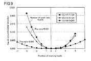
- FIG. 9 shows the gap in a circumferential direction between the internal tooth 11 b and the first and the second external teeth 42 and 52 positioned at the neighborhood area of the reference meshing tooth at one side in a circumferential direction and the other side in a circumferential direction in the horizontal axis direction with respect to the center (O) of the reference meshing tooth and shows the comparison of the case of the ratio of the number of teeth being 0.975, in which the number of external tooth is 117 and the number of internal tooth is 120, of the case of the ratio of the number of teeth being 0.991, in which the number of external tooth is 119 and the number of internal tooth is 120 and of the case of the ratio of the number of teeth being 0.995, in which the number of external tooth is 199 and the number of internal tooth is 200, respectively.
- the vertical axis indicates the gap in a circumferential direction. It is noted that the one side in the circumferential direction of the horizontal axis is defined to be the positive number side and the other side is defined to be the negative number side.
- the circumferential gap is varied from the reference meshing tooth similarly in both circumferential sides. Accordingly, the number of meshing teeth between the internal tooth 11b and the first and the second external teeth 42 and 52 in the one circumferential side with respect to the reference meshing tooth is the same with the number of meshing teeth between the internal tooth 11b and the first and the second external teeth 423 and 52 in the other circumferential side with respect to the reference meshing tooth when the rotational driving force is transmitted.
- Figs. 10 and 11 show the analysis result of the number of the meshing teeth and the maximum surface pressure of the cases of the reduction gear ratios of 39, 99 and 199, respectively, in response to the variation of the load torque. From the results, the maximum surface pressure can be reduced even when the load torque is increased.
- the height of the internal tooth 11b and the first external tooth 42 can be shortened and accordingly, the deflection amount of the internal tooth 11b and the external tooth 42 can be minimized.
- the value of the second term in the formula (16) becomes small. If the deflection amount of the internal tooth 11b and the first external tooth 42 should increase, an undesired contact of the tip end corner of the internal tooth 11b and the first external tooth 42 with the mating tooth flank may occur. This undesired contact may raise a further problem that the surface pressure of the contacted tooth flank may be raised.
- the deflection amount of the internal tooth 11b and the first external tooth 42 can be reduced thereby avoiding any undesired contact of the tip end corner of the internal tooth 11b and the first external tooth 42 with the mating tooth flank. This means that a generation of high surface pressure can be prevented which may arise due to the contact of the tip end corner of the tooth with the mating tooth flank.
- the acceptable load to be received by the first external tooth 42 and the internal tooth 11b can be increased. As the result, further high load torque transmission can be achieved through the internally toothed gear wheel 11 and the first externally toothed gear wheel 40 as a whole.
- the load generated upon the internal tooth body 11a and the first external tooth body 41 becomes smaller as farther away from the position of the reference meshing tooth in a circumferential direction.
- the internal tooth body 11a and the first external tooth body 41 largely elastically deform in an extending direction or in a contracting direction as the position thereof is closer to the reference meshing tooth in a circumferential direction.
- the size of module m becomes small, i.e., when the diameter is the same, the number of the first external tooth 42 and the internal tooth 11b become large.
- the pitch P1i between the adjacent two first external teeth 42 and the pitch 2i between the adjacent two internal teeth 11b become narrow.
- the heat treatment which has been conducted without doubt may be eliminated.
- the surface pressure applied to the tooth drops, in some cases, the surface pressure applied to the tooth may be within the allowable pressure resistance level without conducting a heat treatment. This can reduce the manufacturing cost by eliminating a process for the heat treatment.
- a down-sized, high speed reduction gear ratio device can be achieved since the involute tooth profile can be applied to the swing internal contact type planetary gear device 1. Further on, by providing the same number of internal tooth 11b and the first and second external teeth 42 and 52 which are in meshing engagement with each other in both sides in circumferential direction with respect to the reference meshing tooth, a stable driving torque transmission can be achieved.
- the elastic deformation amount in the area of neighborhood of the reference meshing tooth of each internal tooth body 11a and first and second external tooth bodies 41 and 51 gradually increases and after reaching to the peak, the amount gradually decreases and finally the meshing condition moves to the non-contact condition.
- the driving torque transmission can be surely performed and meshing operation can be performed without giving any sudden application of load to each internal tooth 11b and first and second external teeth 42 and 52.
- the device is excellent in durability.
- the rotation driving device 100 is structured by a motor 180 and the swing internal contact type planetary gear device 101. According to this structure, the rotation driving force of the motor 180 is transmitted to the swing internal contact type planetary gear device 101 to achieve speed reduction operation.
- the motor 180 includes a cylindrically shaped rotor 181 and a cylindrically shaped stator 182 positioned opposite to the rotor 181 outwardly in a radial direction.
- the cylindrical rotor 181 includes, for example, a rotor yoke and a magnet.
- the stator 182 includes a stator core and a coil wound around the stator core.
- the swing internal contact type planetary gear device 101 has basically the same structure as that of the swing internal contact type planetary gear device 1 except the features of a housing 110, an input shaft 120 and a first externally toothed gear wheel 140. Here, only the different points will be explained.
- the housing 110 is formed to have a cylindrical bottom surface at the center of which a circular bore is formed and the housing 110 accommodates the other components of the swing internal contact type planetary gear wheel 101 and the motor 180.
- the stator 182 is fixed to the inner circumferential surface of the housing 110.
- the input shaft 120 (corresponds to "shaft” of the claimed invention) is supported by the housing 110 through a fourth bearing 74 inserted into a circular bore of the housing 110 and rotatable relative to the housing 110 centering on the input/output axial line X1. Further, the input shaft 120 is integrally fixed to the rotor 181 by fitting the rotor 181 of the motor 180 into the shaft. Thus, the input shaft 120 receives the rotation driving force of the rotor 181.
- This input shaft 120 is formed by a base end portion 121, a rotor fitting portion 122, a groove portion 123, a first eccentric body portion 124, a second eccentric body portion 125 and a tip end portion 126 in order from the base end side (right side in Fig. 7 ) and these portions are formed integrally.
- the base end portion 121 is formed with a cylindrical or a columnar shape centering on the input/output axial line X1 as the center axis.
- the fourth bearing 74 is fitted onto the outer circumferential surface of the base end portion 121 and the input shaft 120 is supported on the housing 110 through the fourth bearing 74 and rotatable about the input/output axial line X1 relative to the housing 110.
- the rotor fitting portion 122 is formed to be of cylindrical or columnar shape centering on the input/output axial line X1 as the center axis.
- the outer diameter of the rotor fitting portion 122 is formed to be larger than the outer diameter of the base end portion 121.
- the rotor 181, formed separately from the input shaft 120, is fitted onto the outer circumferential surface of the rotor fitting portion 122 by press-fitting. It is noted here that the contact area between the inner circumferential surface of the rotor 181 and the outer circumferential surface of the rotor fitting portion 122 is preferable set to be larger in order to surely fix the rotor 181.
- the outer diameter of the rotor fitting portion 122 is larger the better in order to surely fix the rotor 181 to the shaft 120.
- the size of the outer diameter of the rotor fitting portion 122 is limited. Accordingly, it is desirable to set the outer diameter of the rotor fitting portion 12 to be the maximum within the above dimensional limitations.
- the first eccentric body portion 124 is a portion integrally formed with the first eccentric body 23 of the first embodiment. However, the outer diameter of the first eccentric body portion 124 is set to be greater than the outer diameter of the first eccentric body 23 of the first embodiment.
- the first eccentric body portion 124 is formed of a hollow shaft or solid shaft shape and includes a circular outer circumferential surface deviated from the input/output axial line X1 and centering on the first eccentric axial line X2.
- the second eccentric body portion 125 is a portion formed integrally with the second eccentric body 24 of the first embodiment.
- the second eccentric body portion 125 is provided at a position closer to the tip end side of the input shaft 220 than the position of the first eccentric body portion 124.
- This second eccentric body portion 125 is formed of a hollow shaft or a solid shaft shape and includes a circular outer circumferential surface deviated from the input/output axial line X1 and centering on the second eccentric axial line X3.
- the phase of the second eccentric axial line X3 is 180 degree (180°) deviated from the phase of the first eccentric axial line X2 with respect to the center line of the input/output axial line X1 with the same eccentric amount to the first eccentric axial line X2.
- the outer diameter of the second eccentric body portion 125 is set to be smaller than the outer diameter of the first eccentric body portion 124.
- the circle (indicated with the dotted line in Fig. 13 ) of the outer circumferential surface of the second eccentric body portion 125 is formed to be positioned inside of the circle of the outer circumferential surface of the first eccentric body portion 124 as viewed from the axial direction.
- the second eccentric body portion 125 is positioned at the tip end side in an axial direction from the axial center of the internally toothed gear wheel 11 formed in the housing 110. Accordingly, when the input shaft 120 is rotated about the input/output axial line X1, the first and the second eccentric body portions 124 and 125 orbit the input/output axial line X1.
- the groove portion 123 is formed between the rotor fitting portion 122 and the first eccentric body portion 124 and has an outer diameter smaller than the outer diameters of the rotor fitting portion 122 and the first eccentric body portion 124.
- the tip end portion 126 is provided at the tip end side, i.e., in the side of the output shaft 30.
- This tip end portion 126 as similar to the base end portion 121, is formed of a hollow shaft or a solid shaft shape centering on the input/output axial line X1 as the center axis.
- the third bearing 73 is disposed on the outer circumferential surface of the tip end portion 126 and the input shaft 120 supports the output shaft 30 and is rotatable relative to the output shaft 30.
- the first externally toothed gear wheel 140 is formed to be of a disc shape having a circular bore at the center thereof.
- the inner circumferential surface of the first externally toothed gear wheel 140 is inserted onto the outer circumferential surface of the first eccentric body portion 124 of the input shaft 120 through the first bearing 71.
- the inner diameter of the first externally toothed gear wheel 140 is set to be larger than the inner diameter of the first externally toothed gear wheel 40 of the first embodiment.
- the first externally toothed gear wheel 140 includes a first external tooth body 141 and a first external tooth 42 similar as the external tooth of the first embodiment.
- the first external tooth body 141 is formed with a plurality of circular through-holes 141a as similar to the through-holes 41a of the first embodiment.
- the circle of the outer circumferential surface of the second eccentric body portion 125 is formed to be positioned inside the circle of the outer circumferential surface of the first eccentric body portion 124 and further, the phase of the first eccentric axial line X2 of the first eccentric body portion 124 is deviated from the phase of the second eccentric axial line X3 of the second eccentric body portion 125 with 180 degree (180°) with respect to the center line of input/output axial line X1.
- the condition that satisfy the circle of the outer circumferential surface of the second eccentric body portion 125 being positioned inside the circle of the outer circumferential surface of the first eccentric body portion 124 can be obtained by the following formula (19).
- phase of the first eccentric axial line X2 of the first eccentric body portion 124 is deviated from the phase of the second eccentric axial line X3 of the second eccentric body portion with 180 degree (180°) with respect to the center line of the input/output axial line X1.
- phase deviation is " ⁇ "
- the condition that satisfies the circle of the outer circumferential surface of the second eccentric body portion 125 being positioned inside the circle of the outer circumferential surface of the first eccentric body portion 124 can be represented by the following formula (20).
- the swing internal contact type planetary gear device 101 since the swing internal contact type planetary gear device 101 is applied to the rotation driving device 100 as stated above, the effects or advantages of the swing internal contact type planetary gear device 101 can be obtained. Further, the first and the second eccentric body portions 124 and 125 of the swing internal contact type planetary gear device 101 in the rotation driving device 100 and the shaft for transmitting the rotation driving force of the rotor 181 are formed integrally as the input shaft 120, the number of part can be reduced and can achieve the down-sizing of the device. However, it is difficult to assemble the first bearing 71 to the first eccentric body portion 124 when the first and the second eccentric body portions 124 and 125 are integrally formed with the input shaft 120.
- the circle of the outer circumferential surface of the second eccentric body portion 125 is positioned inside the circle of the outer circumferential surface of the first eccentric body portion 124 as viewed from the axial direction of the input shaft 120. This can make the first bearing 71 to be easily fitted onto the outer circumferential surface of the first eccentric body portion 124, by passing through the second eccentric body portion 125.
- the rotation driving device 200 using the swing internal contact type planetary gear device 201 will be explained with reference to Fig. 14 .
- the rotation driving device 200 includes a motor 180 the structure of which is the same as the motor in the second embodiment and a swing internal contact type planetary gear device 201, the structure of which is substantially the same as the swing internal contact type planetary gear device 1.
- the housing 210 of this embodiment also is the same structure as that of the housing 110 of the second embodiment.
- the input shaft 220 is different in structure from the input shaft 120 of the second embodiment. The explanation of this embodiment will only be made to the points different from the first and the second embodiments.
- the input shaft 220 is formed by a base end portion 221 (right side in Fig. 14 ), a rotor fitting portion 222, a groove portion 223, a first eccentric body portion 224, a second eccentric body portion 225 and a tip end portion 226 in order from the base end side and these portions are formed integrally.
- the structures of the base end portion 221, the rotor fitting portion 222, the second eccentric body portion 225 and the tip end portion 226 correspond to and are same to the base end portion 121, the rotor fitting portion 122, the second eccentric body portion 125 and the tip end portion 126 of the input shaft 120 of the second embodiment, respectively.
- the diameter of the rotor fitting portion 222 is necessary to be smaller than the inner diameter of the first bearing 71. Accordingly, the outer diameter of the rotor fitting portion 222 is desirably set to be the maximum under the condition that the outer diameter of the rotor fitting portion 222 is smaller than the inner diameter of the first bearing 71.
- the first eccentric body portion 224 is a portion formed integrally with the first eccentric body 23 of the first embodiment.
- the first eccentric body portion 224 is formed to be of hollow shaft or of solid shaft and includes a circular outer circumferential surface centering on the first eccentric axial line which is deviated from the center of the input/output axial line X1.
- the diameter of the first eccentric body portion 224 is set to be larger than the outer diameter of the base end portion 221 according to this embodiment and the same with the diameter of the second eccentric body portion 225.
- the position of the first eccentric body portion 224 is located at the base end side from the axial center of the internally toothed gear wheel 11 formed at the housing 210.
- the groove portion 223 is formed between the rotor fitting portion 222 and the first eccentric body portion 224 in an axial direction and the diameter of the groove portion 223 is set to be smaller than the outer diameter of the rotor fitting portion 222 and smaller than the outer diameter of the first eccentric body portion 224. Further, the width in an axial direction of the groove portion 223 is set to be larger than the width in an axial direction of the first bearing 71 which supports the first externally toothed gear wheel 40 relative to the first eccentric body portion 224.
- the rotor 181 and the rotor fitting portion 222 are separately formed at the portion where the rotor 181 of the motor 180 is placed.
- the first bearing 71 to be assembled to the outer circumferential surface of the first eccentric body portion 224 which is positioned in motor 180 side can be inserted from the motor 180 side.
- the groove portion 223 having a proper outer diameter and width in an axial direction between the first eccentric body portion 224 and the rotor fitting portion 222 the first bearing 71 can be inserted from the motor 180 side and can be assembled to the outer circumferential surface of the first eccentric body portion 224.
- the outer diameter of the first eccentric body portion 224 and the outer diameter of the second eccentric body portion 225 are set to be the same diameter, it is effective to insert the first bearing 71 to be assembled to the outer circumferential surface of the first eccentric body portion 224.
- the electrically assisted bicycle includes a frame body 311, front fork 312, a handle 313, saddle 314, front wheel 315, rear wheel 316, main driving device 317 and an auxiliary driving device 318.
- the frame 311 is the basic portion of the electrically assisted bicycle and a column (steering column) of the front fork 312 is rotatably supported on the head tube of the frame body 311 through the bearing.
- a pair of right and left blades of the front fork 312 (component member at the lower end side) is connected to the column.
- the front wheel 315 is rotatably supported on the lower end (front end) of the blades of the front fork 312.
- the rear wheel 316 is rotatably supported on the rear end of the frame body 311.
- the front and the rear wheels 315 and 316 are formed by a hub 315a, spokes 315b, a rim 315c, a tire 315d (only the numerals for the front wheel structure are referenced).
- the main driving device 317 is a well-known driving device which drives the rear wheel 316 by means of the legs of the human.
- the auxiliary driving device 318 is formed by a main body 320 for the driving device and an electric power supply source device 330.
- the main body 320 for the driving device is provided at the hub 315a of the front wheel 315 and includes a motor 340 and a reduction gear apparatus 360 using a swing internal contact type planetary gear device.
- the electric power supply source device 330 is used for a power source for driving the motor 340 and is fixed to a seat tube of the frame body 311.
- the power supply source device 330 supplies electricity to the motor 340 through a power supply cable (not shown).
- the power supply source device 330 is charged by a re-generation energy system when the motor 340 is used as a generator.
- the main body 320 of the driving device of the auxiliary driving device 318 includes the motor 340 and the reduction gear apparatus 360.
- the motor 340 includes a stator 341 and a rotor 342. This motor 340 is disposed inside of the cylindrical hub 315a of the front wheel 315 in a radial direction.
- the stator 341 is formed of a cylindrical shape and the coil is wound around.
- the stator 341 is fixed to and supported by the lower end (front end) of the blades of the front fork 312 through a later explained cylindrical fixed member 453, fixed cover 454 and a first fixed shaft 451.
- the stator 341 is arranged to be in co-axial with a rotation shaft of the front wheel 315.
- the rotor 342 is disposed inside of the stator 341 in a radial direction with a predetermined gap opposite to the inner circumferential surface of the stator 341 and is arranged in co-axial therewith and is relatively rotatable with the stator 341. In other words, the rotor 342 is rotated about the input/output axial line X1 relative to the stator 341 when the electricity is supplied to the coil of the stator 341.
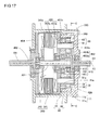
- the reduction gear apparatus 360 uses the swing internal contact type planetary gear device 1 of the first embodiment and accordingly, the same structure and parts thereof are referenced with the same numerals and the detail explanation thereof will be omitted. However, since the operation of the reduction gear apparatus 360 applied to the main body 320 of the driving device of the electrically assisted bicycle is different from the operation of the first embodiment and detail explanation will be made hereinafter.
- the reduction gear apparatus 360 is arranged coaxially with the motor 340 for driving the front wheel 315 by reducing the rotation speed of the driving force of the motor 340.
- the reduction gear apparatus 360 includes an input shaft 410 and an output outer race 420 provided in co-axial with the input shaft 410 and serves as a reduction gear for transmitting the rotation of the input shaft 410 to the output outer race 420 through speed reduction.
- the power supply from the power supply source device 330 to the motor 340 stops and at the same time the reduction gear apparatus 360 functions as an accelerator for transmitting the rotation of the output outer race 420 fixed to the front wheel 315 to the input shaft 410 by accelerating the rotation of the output outer race 420.
- the motor 340 functions as a generator in this case.
- An internally toothed gear wheel 11 which has the same structure as the internally toothed gear wheel 11, is formed on the inner circumferential surface of the output outer race 420.
- the first and the second externally toothed gear wheels 40 and 50 which are structured same as those in the first embodiment are swingably rotated relative to a fixed member 450 when the input shaft 410 is rotated.
- the relative rotation difference between the internally toothed gear wheel 11 and the first and the second externally toothed gear wheels 40 and 50 is outputted to the output outer race 420.
- the functions of the housing 10 and the output shaft 30 in the first embodiment correspond to the functions of the output outer race 420 and the fixed member 450 in the fourth embodiment, respectively.
- the reduction gear apparatus 360 includes the input shaft 410, output outer race 420, fixed member 450, first externally toothed gear wheel 40, second externally toothed gear wheel 50 and a plurality of inner pins 60 having the same structure as the inner pins in the first embodiment.
- the input shaft 410 includes a base end portion 411, a first eccentric body 412 and a second eccentric body 413 in order from the base end side (left side in Fig. 17 ) and these are integrally formed with the input shaft 410.
- the base end portion 411 is formed of a cylindrical or a columnar shape centering on the input/output axial line X1 as the center axis.
- the base portion is fitted into the central bore of the rotor 342 and supported by the fixed cover 454 and is rotatable relative to the fixed cover 454 about the input/output axial line X1.
- the structures of the first eccentric body 412 and the second eccentric body 413 are the same as those of the first eccentric body 23 and the second eccentric body 24 of the first embodiment, respectively.
- the output outer race 420 is formed to be the same as the housing 10 of the first embodiment and inside circumferential surface of the output outer race 420 is formed with an internally toothed gear wheel 11 of the first embodiment.
- the fixed member 450 is fixed to the lower end (front end) of the blades of the front fork 312.
- the fixed member 450 is provided with a first fixed shaft 451, a second fixed shaft 452, fixed cylindrical member 453 and a fixed cover 454.
- the first fixed shaft 451 is of columnar shape and is inserted into one of the blades of the front fork 312 and fixed thereto. This first fixed shaft 451 is provided to be in co-axial with the input/output axial line.
- the second fixed shaft 452 includes a shaft portion 452a and a disc portion 452b integrally formed with one end of the shaft portion 452a.
- the shaft portion 452a of the second fixed shaft 452 is inserted into the other of the blades of the front fork 312 and fixed thereto.
- the second fixed shaft 452 is arranged to be in co-axial with the first fixed shaft 451.
- the shaft portion 452a relatively rotatably supports the output outer race 420 through a bearing.
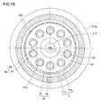
- the disc portion 452b is positioned at the other end side of the shaft portion 452a in the first fixed shaft 451 side. Further, the disc portion 452b is provided with a plurality of circular recessed portions 452c centering around the input/output axial line X1 in a circumferential direction with an equal interval with one another. In other words, each circular center of the circular recessed portions 452c is positioned concyclic having the circle center as the center of the input/output axial line X1. In this embodiment the number of the circular recessed portion is ten (10).
- the fixed cover 454 is formed with a disc shape and is provided with a circular bore centering on the input/output axial line X1.
- the first fixed shaft 451 is inserted into this circular bore and the fixed cover 454 is fixed to the first fixed shaft 451.
- the outer circumferential surface of the fixed cover 454 rotatably supports the hub 315a of the front wheel 315 through a bearing.
- the inner circumferential surface of the fixed cover 454 rotatably supports one end side (left side in Fig. 17 ) of the base end portion 411 of the input shaft 410 through a bearing.
- the fixed cylindrical member 453 has a bottom, a cylindrical portion 453a and a disc portion 453b formed integrally with one end (right side in Fig. 17 ) of the cylindrical portion 453a.
- the other end (left side in Fig. 17 ) of the cylindrical portion 453a of the fixed cylindrical member 453 is fixed to the outer circumferential brim of the fixed cover 454.
- the fixed cylindrical member 453 is fixed to the front fork 312 through the fixed cover 454 and the first fixed shaft 451.
- the stator 341 as stated earlier is fixed to the inner circumferential surface of the cylindrical portion 453a of the fixed cylindrical member 453.
- a circular bore centering on the input/output axial line X1 is provided on the disc portion 453b of the fixed cylindrical member 453. Further, a plurality of circular recessed bores 453c is provided on the disc portion 453b of the fixed cylindrical member 453 centering on the input/output axial line X1 and with an equal interval with one another in a circumferential direction. Each circular center of the circular recessed portions 453c is positioned concyclic having the circle center as the center of the input/output axial line X1.
- Each of the circular recessed portions 453c formed on the disc portion 453b of the fixed cylindrical member 453 is in co-axial with and in the same shape with each corresponding circular recessed portion 452c formed on the disc portion 452b of the second fixed shaft 452.
- the inner circumferential surface of the circular bore of the fixed cylindrical member 453 rotatably supports the other end side (right side in Fig. 17 ) of the base end portion 411 of the input shaft 410 through a bearing.
- the motor 340 is arranged in an axial direction between the disc portion 453b of the fixed cylindrical member 453 and the fixed cover 454.
- the first and the second externally toothed gear wheels 40 and 50 are disposed between the disc portion 452b of the second fixed shaft 452 and the disc portion 453b of the fixed cylindrical member 453 in an axial direction.
- the inner pins 60 are respectively inserted into the circular recessed portions 452c of the disc portion 453b of the second fixed shaft 452 and the circular recessed portions 453c of the disc portion 453b of the fixed cylindrical member 453 and further inserted into the circular through-holes 41a and 51a formed on the first and the second external tooth bodies 41 and 51, respectively.
- the inner pins 60 are inserted into the circular through-holes 41a and 51a of the first and the second external tooth bodies 41 and 51.
- Each inner pin 60 is fixed to the front fork 312 through the fixed member 450. Accordingly, the rotation of the first and the second externally toothed gear wheels 40 and 50 relative to the front fork 312 are restricted.
- the first and the second externally toothed gear wheels 40 and 50 orbit the input/output axial line X1, but do not rotate about the second eccentric axial line X2 and X3.
- the first and the second externally toothed gear wheels 40 and 50 relatively orbit and rotate, when seen from the input shaft 410.
- the first and the second externally toothed gear wheels 40 and 50 orbit while rotation thereof being restricted and accordingly, the phase of meshing engagement with the internally toothed gear wheel 11 of the output outer race 420 among the first and the second externally toothed gear wheels 40 and 50 gradually moves and as a result, the output outer race 420 rotates about the input/output axial line X1 by the number of tooth differences between the first and the second externally toothed gear wheels 40 and 50 and the internally toothed gear wheel 11.
- the output outer race 420 makes a rotation by an angle obtained by multiplying the difference of the number of teeth between the first and the second externally toothed gear wheels 40 and 50 and the internally toothed gear wheel 11 by each inter-dental phase of the internally toothed gear wheel 11. Accordingly, smaller the inter-dental phase value of the internally toothed gear wheel 11 and lesser the number of tooth differences between the first and the second externally toothed gear wheels 40 and 50 and the internally toothed gearwheel 11, more the reduction ratio increases.
- the output outer race 420 is fixed to the hub 315a of the front wheel 315 and accordingly, the output outer race 420 transmits the decelerated driving force of the motor 340 to the hub 315a and auxiliary drives the front wheel 315.
- the output outer race 420 inputs the rotation of the front wheel 315 to accelerate the rotation of the input shaft 410 and by driving the rotor 342, the motor 340 generates the electricity to charge the power supply source device 330.
- the vehicle driving device can be applied to the main driving device for the electrically assisted bicycle.
- the invention can be applied to a driving device for a motorcycle.
- the invention also can be applied to a driving device for an electrically assisted wheel chair. In any case, the effects of the invention can be achieved.
Landscapes
- Engineering & Computer Science (AREA)
- General Engineering & Computer Science (AREA)
- Mechanical Engineering (AREA)
- Chemical & Material Sciences (AREA)
- Combustion & Propulsion (AREA)
- Transportation (AREA)
- Retarders (AREA)
Abstract
Description
- This invention relates to a swing internal contact type planetary gear device and a rotation drive device using the planetary gear device.
- Conventionally, an example of the swing internal contact type planetary gear device is disclosed in a Japanese Patent Application published as
JP2002-266955 A - By thus configuring the reduction gear device, the number of tooth differences between the internally toothed gear wheel and the externally toothed gear wheel can be minimized and accordingly, a high reduction gear ratio can be obtained. Further, according to this structure, since a high meshing ratio between the internally toothed gear wheel and the externally toothed gear wheel can be obtained, these gear wheels are known to have a gear with high rigidity and tensile. In this structure, further higher reduction ratio may be achieved due to the increase of the number of teeth in each internally toothed gear wheel and externally toothed gear wheel. However, by the pin and trochoid tooth profile meshing engagement structure, the device may have a problem in oversized diameter, if the number of tooth is increased.
- While on the other hand, an involute tooth profile is known as a gear wheel, in which a plenty of teeth can be formed on the gear. The gear wheels with involute tooth profile adapted to the swing internal contact type planetary gear device are already disclosed in
JP2009-8143 A JP5 (1993)-34837 B JP2007-24072 A JP1 (1989)-210642 A JP10 (1998)-227340 A - However, it would not be easy to configure the device with minimized tooth difference in number between the internally toothed gear wheel and the externally toothed gear wheel due to an interference caused at the tooth tip portions when an involute tooth profile is adapted to the internally toothed gear wheel and the externally toothed gear wheel. Further, the gear meshing ratio becomes low and the load to be received by the meshing tooth becomes large when the involute tooth profile is used. Accordingly, in order to transmit a large torque, the increase of the rigidity for the toothed gear wheel was necessary.
- According to the disclosure of
JP1 (1989)-210842 - However, the inventors of this application found out a problem that the tip end angled portion of the internal or external tooth may be brought into contact with the tooth flank of the corresponding mating tooth when the internal tooth of the internally toothed gear wheel and the external tooth of the externally toothed gear wheel are deformed. When the tip end angled portion of the internal or external tooth is brought into contact with the tooth flank of the corresponding mating tooth, a high surface pressure is generated at the tooth flank of the mating tooth. In other words, in order to have the surface pressure applied on the mating tooth flank to be within a durable pressure range, the torque to be transmitted eventually had to be decreased due to the receiving surface pressure.
- The present invention was made in consideration with the above problems and the object of the invention is to provide a swing internal contact type planetary gear device which can achieve a high torque transmission as well as the achievement of obtaining a high meshing ratio when the involute tooth profile is adopted. Further, the object of the invention is to provide a rotation driving device using the swing internal contact type planetary gear device.
- It is noted here that as a drive device for an electrically assisted bicycle, the publication
JP2005-278234 A - Accordingly, the object of the invention is to provide a swing internal contact type planetary gear device suitable for use for an electrically assisted bicycle or the like.
- According to the swing internal contact type planetary gear device of the present invention, the device comprises an eccentric body rotating about an input/output axial line and having a center line being an eccentric axial line, the eccentric axial line is deviated from the input/output axial line; an internally toothed gear wheel provided with an annular internal tooth body and a plurality of internal teeth formed integrally with the internal tooth body in an inner circumferential side thereof, the center line thereof being the input/output axial line; and an externally toothed gear wheel provided with an annular external tooth body and a plurality of external teeth formed integrally with the external tooth body in an outer circumferential side thereof, the externally toothed gear wheel being relatively rotatably supported on the eccentric body and swingably rotating relative to the internally toothed gear wheel in meshing engagement therewith under the driving condition, the center line thereof being the eccentric axial line, characterized in that each of the internal and external teeth is provided with an involute tooth profile and under the driving condition, one of the internal tooth body and the external tooth body elastically deforms in an extending direction in a circumferential direction and the other of the internal tooth body and the external tooth body elastically deforms in a contracting direction in a circumferential direction, whereby the number of meshing teeth between the internal tooth and the external tooth is set to be larger than the number of meshing teeth between the internal tooth and the external tooth under a non-driving condition.
- In other words, the number of meshing teeth between the internal tooth and the external tooth is designed to be increased not by the deflective deformation of the internal and the external teeth, but by an elastic deformation of the external and the internal tooth bodies, one of the external and the internal tooth bodies being deformed in an extending direction in a circumferential direction and the other of the external and the internal tooth bodies being deformed in a contracting direction in a circumferential direction.
- Further, it may be that assuming that a tooth number "i" of each of reference meshing teeth of the internal tooth and the external tooth meshing with each other under a non-driving condition is defined as "1" and the number "i" of each of the internal tooth and the external tooth is defined to be the value added every one (1) whenever it is leaving away from the reference meshing tooth, a displacement amount in an extending direction of one of the teeth between the internal tooth and the external tooth, each tooth being numbered as "i", is defined to be the value of δ1,i, a displacement amount in a contracting direction of the other of the teeth between the internal tooth and the external tooth, each tooth being numbered as "i", is defined to be the value of δ2,i, and that, a gap between the tooth flank of the internal tooth and the tooth tip of the external tooth each tooth being numbered as "i", is defined to be the value of δi, wherein, a module of each of the internally toothed gear wheel and the externally toothed gear wheel is set as the value satisfied the following formula (1):
-

- Further, it may be that the displacement amount δ1,i in the extending direction of the one of the teeth between the internal tooth and the external tooth, each tooth being numbered as "i", is defined to be the value obtained by the following formula (2), the displacement amount δ2,i in the contracting direction of the other of the teeth between the internal tooth and the external tooth, each tooth being numbered as "i", is defined to be the value obtained by the following formula (3) and the gap δi between the tooth flank of the internal tooth and the tooth tip of the external tooth each tooth being numbered as "i" is defined to be the value obtained by the following formula (4):
-

- δ1,i : Displacement amount of the i-th tooth from the reference meshing tooth in an extending direction.
- P1,i: Pitch width of the i-th tooth from the reference meshing tooth.
- δ1,i: Effective cross sectional area of the i-th tooth from the reference meshing tooth.
- F1,i: Force received by the i-th tooth of the one of the external tooth and the internal tooth from the reference meshing tooth and applied by the other of the external tooth and the internal tooth.
- E: Longitudinal elastic modulus of the one of the externally toothed gear wheel and the internally toothed gear wheel.
- T: Force transmitted between the externally toothed gear wheel and the internally toothed gear wheel.
- Δt1,i: Deflection amount of the i-th tooth of the one of the internal tooth and the external tooth from the reference meshing tooth in a circumferential direction.
- αx1: Random circular pressure angle from the base circle to the tooth tip. wherein, the suffix "1" means one of the externally toothed gear wheel and the internally toothed gear wheel.
-

- δ2,i: Displacement amount of the i-th tooth from the reference meshing tooth in a contracting direction.
- P2,i: Pitch width of the i-th tooth from the reference meshing tooth.
- S2,i: Effective cross sectional area of the i-th tooth from the reference meshing tooth.
- F2,i: Force applied by the external tooth and received by the i-th tooth from the reference meshing tooth.
- E: Longitudinal elastic modulus of the other of the externally toothed gear wheel and the internally toothed gear wheel.
- T: Force transmitted between the externally toothed gear wheel and the internally toothed gear wheel.
- Δt2,i: Deflection amount of the i-th tooth of the other of the internal tooth and the external tooth from the reference meshing tooth in a circumferential direction.
- αx1 and αx2: Random circle pressure angle from the base circle to the tooth tip. Wherein, the suffix "2" means the other of the externally toothed gear wheel and the internally toothed gear wheel.
-

- δi: Gap between the i-th external tooth tip and internal tooth flank from the reference meshing tooth.
- f(m,α,z 1 ,z 2 ,x 1 ,x 2 ,α): Function having variables of , α, z 1,z 2,x 1,x 2,α.
- m: Module.
- z1,z2,: Number of teeth.
- α: Reference pressure angle.
- x 1, x 2,: Addendum modification coefficient.
- a: Distance between the centers.
- X2,i,Y2,i : The i-th internal tooth meshing point coordinate (X,Y) when the i-th internal tooth from the reference meshing tooth joins the meshing operation in the O-XY coordinate with the center "O" of the internally toothed gear wheel as the reference point.
- X1,i,Y 1 ,i : The i-th external tooth meshing point coordinate (X,Y) when the i-th external tooth from the reference meshing tooth joins the meshing operation in the O-XY coordinate with the center "O" of the internally toothed gear wheel as the reference point.
- The first term in the formula (2) represents the elastic deformation amount extending in a circumferential direction of one of the internal tooth body and the external tooth body and the first term in the formula (3) represents the elastic deformation amount contracting in a circumferential direction of the other of the internal tooth body and the external tooth body. In other words, the formula (1) indicates the total displacement amount of the displacement amount of one of the internal tooth and the external tooth in an extending direction and the displacement amount of the other of the internal tooth and the external tooth in a contracting direction agrees to the gap value between the external tooth tip and the internal tooth flank when the internal tooth body and the external tooth body are elastically deformed either in extending or contracting direction in a circumferential direction. By designing the internally toothed gear wheel and the externally toothed gear wheel using the formula (1), the effects or the performance of the invention explained above can be surely achieved.
- Further, it may be that the module of each of the internally toothed gear wheel and the externally toothed gear wheel is set as the value satisfied the formula (1) or less than the value thereof, wherein the number "i" satisfies the condition "i=2". The condition that satisfies " i=2 " in the formula (1) means the condition that an internal tooth and an external tooth each neighboring to the reference meshing tooth are in contact with each other. Accordingly, the number of meshing teeth is counted as at least two.
- Further, it is preferable to design the module size of the internally toothed gear wheel and the externally toothed gear wheel as small as possible in order to increase the number of meshing teeth by elastically deforming the external tooth body and the internal tooth body in a circumferential direction. By downsizing the module, the tooth height of the internal tooth and the external tooth can be shortened to, thereby, reduce the deflection amount of the internal tooth and the external tooth. Thus, an undesired contact of the tooth tip of the internal and external teeth with the mating tooth flank can be prevented. In other words, high surface pressure problem caused by the contact of the tooth tip can be prevented and accordingly, the load to be received by the external and the internal teeth can be increased to be able to transmit a further larger torque as an entire structure due to the decrease of surface pressure generated between the external tooth and the internal tooth.
- The load generated at the internal tooth body and the external tooth body becomes smaller when the bodies retreat in a circumferential direction from the internal tooth and the external tooth meshing with each other under the non-driving condition, defined as the reference meshing tooth. In other words, the internal tooth body and the external tooth body are greatly elastically deformed in extending or contracting direction; when positioned closer to the reference tooth in the circumferential direction. According to the invention, since the size of the module can be downsized, the number of the external teeth and the internal teeth becomes large. In other words, the pitch between the neighboring external teeth and the pitch between the neighboring internal teeth become narrow. Then, a number of internal and the external teeth can be positioned at the location closer to the reference tooth in a circumferential direction. Accordingly, a number of such internal and the external teeth may join the gear meshing engagement. As stated, by minimizing the size of the module, the condition that a plenty of the internal and external teeth can join the meshing engagement can be created as the result.
- Further, by minimizing the size of module, the involute tooth profile of the internal and external teeth can be shaped to be rather in a shape of a straight line. This may increase the contact surface area between the internal and external teeth thereby reducing the surface pressure generated at the internal and external teeth. Accordingly, further high torque transmission can be achieved as the total structure of internally toothed gear wheel and the externally toothed gear wheel. Further, by minimizing the size of the module, the gap between the flanks of the neighboring internal and the external teeth can be also minimized. In this aspect too, can increase the number of internal and external teeth which can join the meshing engagement.
- Further, by decreasing the surface pressure to be received by each tooth, under some cases, the heat treatment process may be eliminated, which has been considered to be an inevitable process for the gear teeth manufacturing. Conventionally, in order to strengthen the pressure durability, the heat treatment has been conducted. However, according to the invention, by reducing the surface pressure, there may be cases where the pressure durability level is within the permissible range without conducting any heat treatment process. This can reduce the cost of manufacturing gear. Furthermore, by setting the module which satisfies the condition that the value "i" equals to 2 (i=2), the number of meshing teeth surely is counted as at least two or more. Thus the effects and performance stated above can be sure to be achieved.
- The rotation driving device includes a motor having a cylindrically shaped rotor and a cylindrically shaped stator disposed opposite to the rotor outwardly in a radial direction thereof, the swing internal contact type planetary gear device, and a shaft transmitting a rotation of the motor to the eccentric body of the swing internal contact type planetary gear device. The eccentric body includes a first eccentric body having a center line being a first eccentric axial line, the first eccentric axial line deviated from the input/output axial line, and a second eccentric body having a center line being a second eccentric axial line, the second eccentric axial line deviated from the input/output axial line in a different direction from the direction of the first eccentric axial line. The externally toothed gear wheel includes a first externally toothed gear wheel relatively rotatably supported on the first eccentric body, and a second externally toothed gear wheel relatively rotatably supported on the second eccentric body. The shaft includes a rotor fitting portion for receiving at an outer circumferential surface thereof the rotor which is formed separately from the rotor fitting portion, a first eccentric body portion formed integrally with the first eccentric body, and a second eccentric body portion formed integrally with the second eccentric body at the opposite side of the rotor fitting portion relative to the first eccentric body. A circle of an outer circumferential surface of the second eccentric body portion is formed to be smaller than the outer diameter of a circle of an outer circumferential surface of the first eccentric body portion and is positioned inside of the circle of the outer circumferential surface of the first eccentric body portion when viewed from an axial direction of the shaft.
- Since the rotation driving device uses the swing internal contact type planetary gear device, the structure has the effects stated above. Further, since the eccentric body of the swing internal contact type planetary gear device in the rotation driving device and the shaft which transmits rotation driving torque of the rotor are formed integrally, the number of parts can be reduced and also the overall size can be reduced. However, in this integrally formed shaft of the rotor and the eccentric body, if the plural number of the eccentric body is formed (such as first eccentric body portion and the second eccentric body portion), it would be very difficult to install the bearings into the first and the second eccentric portions.
- Accordingly, by reducing the outer diameter of the second eccentric body portion to be smaller than the outer diameter of the first eccentric body portion, the outer circumferential surface of the second eccentric body portion positions inside of the outer circumferential surface of the first eccentric body portion when viewed from the axial direction of the shaft. Thus the bearing to be installed at the outer circumferential surface of the first eccentric body portion can be easily inserted into the first eccentric body portion passing through the second eccentric body portion.
- The rotation driving device includes a motor having a cylindrically shaped rotor and a cylindrically shaped stator disposed opposite to the rotor outwardly in a radial direction thereof, the swing internal contact type planetary gear device, and a shaft transmitting a rotation of the motor to the eccentric body of the swing internal contact type planetary gear device. The eccentric body includes a first eccentric body having a center line being a first eccentric axial line, the first eccentric axial line deviated from the input/output axial line, and a second eccentric body having a center line being a second eccentric axial line, the second eccentric axial line deviated from the input/output axial line in a different direction from the direction of the first eccentric axial line. The externally toothed gear wheel includes a first externally toothed gear wheel relatively rotatably supported on the first eccentric body, and a second externally toothed gear wheel relatively rotatably supported on the second eccentric body. The shaft includes a rotor fitting portion for receiving at an outer circumferential surface thereof the rotor which is formed separately from the rotor fitting portion, a first eccentric body portion formed integrally with the first eccentric body, a second eccentric body portion formed integrally with the second eccentric body at the opposite side of the rotor fitting portion relative to the first eccentric body, and a groove portion formed between the rotor fitting portion and the first eccentric body portion in an axial direction, having a diameter smaller than an outer diameter of the rotor fitting portion and an outer diameter of the first eccentric body portion, and having a width in an axial direction wider than a width in an axial direction of a first bearing which supports the first externally toothed gear wheel relative to the first eccentric body portion.
- As another means taken different from the means above, by forming a rotor and a rotor fitting portion separately at the portion where the rotor of the motor is disposed, a bearing to be installed at the outer circumferential surface of the first eccentric body portion positioned at the motor side can be inserted from the motor side. By providing a groove portion between the first eccentric body portion and the rotor fitting portion with a proper length outer diameter and a width in an axial direction, the bearing can be inserted from the motor side and installed at the outer circumferential surface of the first eccentric body portion.
-
-
Fig. 1 (first embodiment) is an axial cross sectional view of the swing internal contact type planetary gear device. -
Fig. 2 is a cross sectional view taken along the line A-A ofFig. 1 . -
Fig. 3 indicates each position of a portion of the internal tooth and the first and the second external teeth showing the meshing condition of the internal and the external teeth under the non-driving condition. -
Fig. 4 is a view showing the dimensions of the internal tooth and the first and the second external teeth. -
Fig. 5 is a partial exploded view of the internal tooth and the first and the second external teeth. -
Fig. 6 is a view showing the performance of the load applied on each tooth phase from the reference meshing tooth. -
Fig. 7 indicates the FEM analysis result showing the number of meshing teeth corresponding to the ratio value between the first and the second external teeth and the internal tooth. -
Fig. 8 indicates the FEM analysis result showing the number of meshing teeth relative to the number of internal teeth. -
Fig. 9 indicates the FEM analysis result showing a circumferential gap between the internal tooth and the first and the second external teeth relative to the position of the meshing tooth. -
Fig. 10 indicates the FEM analysis result showing the number of meshing teeth relative to the load torque. -
Fig. 11 indicates the FEM analysis result showing the maximum surface pressure relative to the load torque. -
Fig. 12 (second embodiment) is an axial cross sectional view of the rotation driving device. -
Fig. 13 is a cross sectional view taken along the line B-B ofFig. 12 . -
Fig. 14 (third embodiment) is an axial cross sectional view of the rotation driving device. -
Fig. 15 (fourth embodiment) shows an electrically assisted bicycle. -
Fig. 16 is an enlarged view of the front wheel of the electrically assisted bicycle viewed from the direction orthogonal to the axis of the wheel. -
Fig. 17 is an axial cross sectional view of the driving device provided at the hub of the front wheel of the electrically assisted bicycle. -
Fig. 18 is a cross sectional view taken along the line C-C ofFig. 17 . - The structure of the swing internal contact type
planetary gear device 1 of the embodiment will be explained hereinafter with reference to the attached drawings,Fig. 1 andFig. 2 . The swing internal contact typeplanetary gear 1 functions as a speed reduction gear device having aninput shaft 20 and anoutput shaft 30 provided co-axially with the input shaft and transmits rotation of theinput shaft 20 to theoutput shaft 30 by reducing the rotational speed of the input shaft. This speed reduction gear device can be also used as a speed increase gear device by reversing the input/output rotation between theinput shaft 20 and the output shat 30. - The swing internal contact type
planetary gear device 1 is summarized by the device which includes an internallytoothed gear wheel 11 formed at an inner circumferential surface of thehousing 10 and the firstexternal tooth 40 and the secondexternal tooth 50 are swingably rotated relative to thehousing 10 by the rotation of theinput shaft 20. The rotation difference generated by the relative rotation between the internallytoothed gear wheel 11 and the first and the second externally toothed gear wheels is outputted to theoutput shaft 30. - Detail of the swing internal contact type
planetary gear device 1 will be explained hereinafter. The swing internal contact typeplanetary gear device 1 is formed by thehousing 10, theinput shaft 20, theoutput shaft 30, the first and the second externallytoothed gear wheels inner pins 60 . - The
housing 10 is formed with a cylindrical shape having a bottom surface. Thehousing 10 accommodates therein a tip end side of theinput shaft 20, a base end side of theoutput shaft 30 and the first and the second externallytoothed gear wheels housing 10 is provided with a circular bore centering on the input/output axial line X1 and afourth bearing 74 is inserted into the bore. - An internally
toothed gear wheel 11 is provided on the inner circumferential surface of the cylindrically shaped portion of thehousing 10. The internallytoothed gear wheel 11 may be formed integrally with thehousing 10 or may be separately formed and thereafter attached to thehousing 10. The internallytoothed gear wheel 11 is formed with an annularinternal tooth body 11a and a plurality ofinternal teeth 11b integrally formed on the inner circumferential surface side of theinternal tooth body 11 a. The internallytoothed gear wheel 11 is a gear wheel having the center on the input/output axial line X1. In other words, the central position of the pitch diameter accords to the input/output axial line X1. Further, theinternal teeth 11 b are formed of involute tooth profile and the internallytoothed gear wheel 11 is formed by a steel material and normally formed through heat treatment process. It is noted here that theinternal tooth 11b of the internallytoothed gear wheel 11 receiving only a small surface pressure may be formed without heat treatment process. - The
input shaft 20 is supported by thefourth bearing 74 which is inserted into the circular bore of thehousing 10 and rotatable relative to the housing centering on the input/output axial line X1. Theinput shaft 20 is to be connected to a rotation driving source, such as a motor or an internal combustion engine and inputs the rotation driving force. Theinput shaft 20 is formed by abase end portion 21, first and secondeccentric bodies tip end portion 22, in order from the base end side (right side inFig. 1 ). These elements are integrally formed with theinput shaft 20. - The
base end portion 21 is formed with a cylindrical shape or a columnar shape centering on the input/output axial line X1 as a central axis and is supported on thehousing 10. Thebase end portion 21 is rotatable relative to the housing centering on the input/output axial line X1. Thebase end portion 21 is connected to the rotation driving source. Thetip end portion 22 is provided at the tip end side (left side inFig. 1 ) of theinput shaft 20, i.e., at theoutput shaft 30 side. Thistip end portion 22 is formed with a cylindrical shape or a columnar shape centering on the input/output axial line X1 as similar to thebase end portion 21. Athird bearing 73 is arranged on the outer circumferential surface of thetip end portion 22. Thetip end portion 22 supports theoutput shaft 30 and is relatively rotatable therewith as will be explained later. - The first
eccentric body 23 is formed with a hollow shaft shape or a solid shaft shape and includes a circular outer circumferential surface centering on the first eccentric axial line X2 which is deviated from the input/output axial line X1. The outer diameter of the firsteccentric body 23 is set to be larger than the outer diameter of thebase end portion 21 in this embodiment. The firsteccentric body 23 is positioned in the base end side (right side inFig. 1 ) in an axial direction from the axial center of the internallytoothed gear wheel 11 formed on thehousing 10. - The second
eccentric body 24 is positioned in the tip end side (left side inFig. 1 ) of theinput shaft 20 in further tip end side than the position of the firsteccentric body 23. This secondeccentric body 24 is formed with a hollow shaft shape or a solid shaft shape and includes a circular outer circumferential surface centering on the second eccentric axial line X3 which deviated from the input/output axial line X1. The diameter of the secondeccentric body 23 is set to be the same diameter as the firsteccentric body 23. The phase of the second eccentric axial line X3 is deviated by 180 degree from the first eccentric axial line X2 relative to the input/output axial line X1 with an eccentric amount same as that of the first eccentric axial line X2. The secondeccentric body 24 is positioned in the tip end side (left side inFig. 1 ) in an axial direction from the axial center of the internallytoothed gear wheel 11 formed on thehousing 10. Accordingly, when theinput shaft 20 rotates centering on the input/output axial line X1, the first and the secondeccentric bodies input shaft 20 are orbiting the input/output axial line X1. - The
output shaft 30 is supported on thehousing 10 and theinput shaft 20 by a bearing (not shown) which is inserted into thehousing 10 and athird bearing 73 which is inserted into the outer circumferential surface of thetip end portion 22 of theinput shaft 20 and is rotatable relative to thehousing 10 and theinput shaft 20 centering on the input/output axial line X1. Thisoutput shaft 30 is positioned at more left side inFig. 1 than the position of theinput shaft 20 and includes aflange portion 31 and ashaft portion 32. Theflange portion 31 is formed with a disc shape having a circular bore in the center thereof. The inner circumferential surface of theflange portion 31 is rotatably supported on thetip end portion 22 of theinput shaft 20 through thethird bearing 73. Further, a plurality of circular recessedportions 31a are provided at one end surface of theflange portion 31 in a circumferential direction about the input/output axial line X1 with an equal interval with one another. In other words, each circular central position of the circular recessedportions 31a is positioned on the concyclic point about the input/output axial line X1. According to this embodiment, the number of circular recessedportion 31a is exampled as ten (10). Theshaft portion 32 of theoutput shaft 30 is integrally formed on the other end surface (left end surface inFig. 1 ) of theflange portion 31 and coaxial therewith. Theshaft portion 32 is formed with a cylindrical or a columnar shape centering on the input/output axial line X1. - The first externally
toothed gear wheel 40 is formed with a disc shape having a circular bore at the center thereof. The inner circumferential surface of the first externallytoothed gear wheel 40 is inserted into the outer circumferential surface of the firsteccentric body 23 of theinput shaft 20 through thefirst bearing 71. In other words, the first externallytoothed gear wheel 40 is supported on the firsteccentric body 23 and rotatable relative thereto centering on the first eccentric axial line X2. Due to the eccentricity of the firsteccentric body 23 relative to the input/output axial line X1, the first externallytoothed gear wheel 40 orbits the input/output axial line X1 in thehousing 10 and at the same time rotates about the first eccentric axial line X2. - The first externally
toothed gear wheel 40 includes an annular firstexternal tooth body 41 and a plurality of firstexternal teeth 42 formed integrally with the firstexternal tooth body 41 at the outer circumferential surface side thereof. In other words, the first externallytoothed gear wheel 40 is a gear wheel having a center line being the first eccentric axial line X2. Accordingly, the pitch circle center position of the firstexternal tooth 42 accords to the first eccentric axial line X2. Further the firstexternal tooth 42 is formed with an involute tooth profile. The pitch diameter of the first externallytoothed gear wheel 40 is set to be smaller than the pitch diameter of the internallytoothed gear wheel 11 formed on thehousing 10 by the amount of eccentricity of the first eccentric axial line X2 relative to the input/output axial line X1. Accordingly, the first externallytoothed gear wheel 40 is in meshing relationship with the internallytoothed gear wheel 11, partially inscribing the internallytoothed gear wheel 11. In other words, the first externallytoothed gear wheel 40 swingably and relatively rotatably engages with the internallytoothed gear wheel 11 with meshing engagement therewith. - The axial width of the first externally
toothed gear wheel 40 is set to be the value half of the length of the axial width of the internallytoothed gear wheel 11. Further, the first externallytoothed gear wheel 40 engages with the half of the internallytoothed gear wheel 11 at one side (right side inFig. 1 ) in an axial direction. Further, the first externallytoothed gear wheel 40 is formed with the same material with the internallytoothed gear wheel 11. - Further, a plurality of circular through-
holes 41 a is provided in an equal interval with one another at the center of the firstexternal tooth body 41 in a radial direction circumferentially centering on the first eccentric axial line X2. In other words, each circular center position of the circular through-holes 41a positions at concyclic point about the first eccentric axial line X2. The number of the circular through-holes 41a is the same as the number of circular recessedportions 31 a formed on theflange portion 31. The inner diameter of the circular through-hole 41 a is set to be larger than the inner diameter of the circular recessedportion 31 a and as viewed from the axial direction of the input/output axial line X1, the respective circular through-holes 41 a are formed and positioned so that the entire portion of the respective circular recessedportions 31 a formed on theflange portion 31 corresponding respectively to the circular through-holes 41 a can be visually observed. - The second externally
toothed gear wheel 50 is formed with the same material as the first externallytoothed gear wheel 40 and the same heat treatment is conducted. In other words, the second externallytoothed gear wheel 50 includes an annular secondexternal tooth 51 and a plurality of secondexternal teeth 52 formed integrally with the secondexternal tooth body 51 at the outer periphery side thereof. The inner circumferential surface of the secondexternal tooth body 51 is inserted into the outer periphery side of the secondeccentric body 24 of theinput shaft 20 through thesecond bearing 72. In other words, the second externallytoothed gear wheel 50 is rotatably supported on the second externallytoothed gear wheel 50 centering on the second eccentric axial line X3. Further, since the secondeccentric body 24 is deviated from the input/output axial line X1, the second externallytoothed gear wheel 50 is provided to orbit the input/output axial line X1 and rotates about the second eccentric axial line X3. In other words, the second externaltoothed gear wheel 50 is a gear wheel having a center line being the second eccentric axial line X3 and accordingly, the center position of the pitch circle of the secondexternal teeth 52 agrees to the second eccentric axial line X3. - Thus, the second externally
toothed gear wheel 50 has a partially inscribing engagement relationship with the internallytoothed gear wheel 11. In other words, the second externallytoothed gear wheel 50 engages with the internallytoothed gear wheel 11 and rotates relatively and swingably relative to the internally toothed gear wheel. Further, the width in an axial direction of the second externallytoothed gear wheel 50 is set to be the half of the width in axial direction of the internallytoothed gear wheel 11. The second externallytoothed gear wheel 50 meshes with the half of the other side (left side inFig. 1 ) in an axial direction of the internallytoothed gear wheel 11. - Further, a plurality of circular through-
holes 51a is provided in an equal interval with one another at the center of the secondexternal tooth body 51 in a radial direction circumferentially centering on the second eccentric axial line X3. In other words, each circular center position of the circular through-holes 51a positions at concyclic point about the second eccentric axial line X3. The number of the circular through-holes 51a is the same as the number of circular recessedportions 31a formed on theflange portion 31. The inner diameter of the circular through-hole 51a is set to be larger than the outer diameter of the circular recessedportion 31a and as viewed from the axial direction of the input/output axial line X1, the respective circular through-holes 51a are formed and positioned so that the entire portion of the respective circular recessedportions 31a formed on theflange portion 31 corresponding respectively to the circular through-holes 41 a can be visually observed. - Each
inner pin 60 is formed by apin body 61 and a slidingbearing 62 formed with a cylindrical shape and inserted into thepin body 61. Thepin body 61 is inserted into the circular recessedportion 31a formed on theflange portion 31 of theoutput shaft 30 and is projecting in an axial direction from the one end surface (right end surface inFig. 1 ) of theflange 31. Thepin body 61 is formed to be penetrating through the circular through-holes external tooth bodies bearing 62 is inserted into the outer periphery of thepin body 61. The outer diameter of the slidingbearing 62 is set to be smaller than the inner diameter of each circular through-hole Figs. 1 and2 , a portion of the outer circumferential surface of the slidingbearing 62 is in contact with a portion of the inner circumferential surface of the circular through-holes input shaft 20, the contact portion between the slidingbearing 62 and the circular through-holes - The operation of thus structured swing internal contact type
planetary gear device 1 will be explained hereinafter. First, when the rotation driving force is transmitted to theinput shaft 20 from the rotation driving source such as a motor or an internal combustion engine, theinput shaft 20 is rotated about the input/output axial line X1. In response to this rotation of theinput shaft 20, the first and the secondeccentric bodies toothed gear wheel 40 meshes with the internallytoothed gear wheel 11 and rotates about the first eccentric axial line X2 by the amount corresponding to the difference in the number of teeth between the firstexternal tooth 42 and theinternal tooth 11 b. On the other hand, the second externallytoothed gear wheel 50 orbits the input/output axial line X1 in response to the orbiting movement of the secondeccentric body 24. Then the second externallytoothed gear wheel 50 meshes with the internaltoothed gear wheels 11 and rotates about the second eccentric axial line X3 by the amount corresponding to the tooth difference between the secondexternal tooth 52 and theinternal tooth 11b. - It is noted here that the
inner pin 60 is inserted into the circular through-holes external tooth bodies bearing 62 is in sliding contact with the inner circumferential surface of the circular through-holes toothed gear wheels toothed gear wheels housing 10. - Next, the outline structures of the internally
toothed gear wheel 11 and the first and the second externallytoothed gear wheels Fig. 3 . The involute tooth profile is applied to theinternal tooth 11 b and the first and the secondexternal teeth internal tooth 11b and the first and the secondexternal teeth toothed gear wheel 11 and the first and the second externallytoothed gear wheels - The important point is that by elastically deforming the internally
toothed gear wheel 11 and the first and the second externallytoothed gear wheels internal tooth body 11a and the first and the secondexternal tooth bodies internal tooth body 11a and the first and the secondexternal tooth bodies toothed gear wheel 11 and the first and the second externallytoothed gear wheels internal tooth body 11a and the first and the secondexternal tooth bodies internal tooth 11b and the first and the secondexternal teeth internal tooth 11b and the first and the secondexternal teeth - For this purpose, as shown in
Fig. 3 , under the non-driving condition, it is necessary to design the gap W in a circumferential direction between the non-meshing tooth flank of theinternal tooth 11b and the tooth flanks of the first and the secondexternal teeth internal tooth 11b and the tooth flanks of the first and the secondexternal teeth internal tooth 11b in a circumferential direction under the driving condition and the extending direction displacement of the first and the secondexternal teeth internal tooth 11b and the first and the secondexternal teeth - Next, a concrete design method concept for designing the structure of the above mentioned internally
toothed gear wheel 11 and the first and the second externallytoothed gear wheels Figs. 4 through 6 . It is noted here that in order for simplifying the explanation, only the designing of the internallytoothed gear wheel 11 and the first externallytoothed gear wheel 40 will be explained. It is noted that the design of the second externallytoothed gear wheel 50 is the same as that of the first externallytoothed gear wheel 40. - First, the specifications of each tooth will be explained with reference to
Fig. 4 . The specifications of each tooth are defined as follows. Regarding to the firstexternal tooth 42, suffix for each symbol is defined to be "1" and regarding to theinternal tooth 11b, the suffix for each symbol is defined to be "2". Further, inFig. 4 , the pitch circle of theinternal tooth 11b is defined to be "C2a", the base circle thereof is defined to be"C2b", and the pitch circle of the firstexternal tooth 42 is defined to be "c1a", and the base circle thereof is defined to be"c1b". -
- m: Module
- z1 z2: The number of teeth
- α: Reference pressure angle
- x1,x2: Addendum modification coefficient
- r1a r2a: Tooth tip circle radius
- Using the above specifications, the following tooth specifications are represented by the formulae (5) through (9).
-
- α': Meshing pressure angle
- α1x α2x: Random circle pressure angle from base circle to tooth tip
- a: Center to center distance
- r1, r2 : Pitch circle radius
- r1b, r2b: Base circle radius
- r1x, r2x : Random circle radius from base circle to tooth tip
-

Wherein, invα=tanα-α
inv(): Involute function -

-

-

-

- Next, the theory for calculating the gap δ1 between the tooth flanks of the
interval tooth 11 b and the firstexternal tooth 42 upon meshing engagement between the internallytoothed gear wheel 11 and the first externallytoothed gear wheel 40 will be explained with reference toFig. 4 andFig. 5 . It is noted that in order to simplify the explanation,Fig. 5 shows a horizontally exploded view of theinternal tooth 11b and the firstexternal tooth 42 and that each tooth flank is figured as a straight line profile, not an involute profile. Further, the respective positions of theinternal tooth 11b and the firstexternal tooth 42 are indicated with suffix "i" as the tooth number. The tooth which number "i" is 1(i=1) is theinternal tooth 11b and the firstexternal tooth 42 contacting with each other under the non-driving condition and thistooth number 1 is defined as the reference meshing tooth. The value of the tooth number "i" becomes increased number by one (1) by each in order of the tooth away from the reference meshing tooth in a circumferential direction. - First, the pressure angle αi (meshing pressure angle) of each flank on the meshing line of the
internal tooth 11b and the firstexternal tooth 42 which are the "i-th" tooth from the reference meshing tooth is calculated according to the formula (10). -

αi: The i-th tooth pressure angle from the reference meshing tooth on the meshing line of the internally toothed gear wheel and the externally toothed gear wheel, wherein the reference meshing tooth is the tooth "i" =1. - Next, a coordinate point where the first
external tooth 42 has a chance of joining the meshing engagement on the random circle from the base circle c1 b of the firstexternal tooth 42 to the tooth tip of the firstexternal tooth 42 is calculated. The coordinate (xi , yi) of the meshing point of the firstexternal tooth 42 on the o-xy coordinate system having thecenter 0 of the first externallytoothed gear wheel 40 as the reference point according to the formula (11). -

xi , yi : The i-th tooth meshing point in the x, y coordinate when the i-th tooth from the reference meshing tooth joins the meshing engagement in the o-xy coordinate system referencing the center O of the externally toothed gear wheel. - The meshing point of the first
external tooth 42 of the coordinate point (xi,y¡) is converted into the coordinate (Xi,Yi) of the O-XY coordinate system referencing the center O of the internallytoothed gear wheel 11. This can be represented as the formula (12). -

- Then, using the coordinate (x, y) of the meshing point of the first
external tooth 42 calculated by the formula (12), the pressure angle α2,i of theinternal tooth 11 b corresponding to each firstexternal tooth 42 is calculated according to the formula (13). Further, the coordinate (X1,i, Y1,i) of the meshing point of theinternal tooth 11b in the O-XY coordinate system referencing the center O of theinternal tooth 11b is calculated according to the following formula (14). -

α2,i : Pressure angle of the internal tooth corresponding to the i-th external tooth from the reference meshing tooth. -

- By the formulae (12) and (14), the gap δ1 between the tooth flank of the i-th
internal tooth 11b from the reference meshing tooth and the tooth tip of the firstexternal tooth 42 is represented as the formula (15). Thus the gap δ1 can be calculated. Accordingly, the gap δ1 is represented as the function with the variables of the module m, the reference pressure angle α, the number of teeth z1, z2, the addendum modification coefficient x1 x2 and the center to center distance "a". -

δi: Gap between the i-th external tooth tip and internal tooth flank from the reference meshing tooth
f(m, α,z 1, z 2, x 1, x 2, a) : Function having variables of m, α, z 1, z 2, x 1, x 2, a - Next, the displacement amount of each tooth displaced by the force received by the each tooth when the transmitting force is T [N] transmitted between the first externally
toothed gear wheel 40 and the internallytoothed gear wheel 11 is calculated. It is noted here that as shown inFig. 5 , when as the reference meshing tooth, the firstexternal tooth 42 and theinternal tooth 11b are in meshing engagement, the neighborhood area of the reference meshing tooth of the firstexternal tooth body 41 is elastically deformed in an extended direction in circumferential direction by the transmitting force T. On the other hand, the neighborhood area of the reference meshing tooth of theinternal tooth body 11 a is elastically deformed in a contracting direction in a circumferential direction by the transmitting force T. Further, the neighborhood area of the reference meshing tooth of the firstexternal tooth 42 is deflected and deformed by the force received from the correspondinginternal tooth 11 b. On the other hand, the neighborhood area of the reference meshing tooth of theinternal tooth 11b is deflected and deformed by the force received by the correspondingexternal tooth 42. - in other words, the displacement amount δ1,i of the first
external tooth 42 towards the circumferential and extending direction and the displacement amount δ2,i towards the circumferential contracting direction are calculated by the following formula (16). It is noted here that the first term of the first formula in the first equation of the formula (16) corresponds to the elastic deformation amount in circumferential and extending direction of the firstexternal tooth body 41 and the second term corresponds to the deflected deformation of the firstexternal tooth 42. Further, the second term of the second equation of the formula (16) corresponds to the elastic deformation amount in circumferential and contracting direction of theinternal tooth body 11a and the second term corresponds to the deflected deformation of theinternal tooth 11b. -

- δ1,i : Displacement amount in an extending direction of the i-th external tooth from the reference meshing tooth.
- δ2,i : Displacement amount in a contracting direction of the i-th internal tooth from the reference meshing tooth.
- P1,i : Pitch width of the i-th external tooth from the reference meshing tooth
- P2,i : Pitch width of the i-th internal tooth from the reference meshing tooth
- S1,i : Effective area of the i-th external tooth from the reference meshing tooth
- S2,i : Effective area of the i-th internal tooth from the reference meshing tooth
- F 1,i : Force from the internal tooth received by the i-th external tooth from the meshing tooth
- F 2,i : Force from the external tooth received by the i-th internal tooth from the meshing tooth
- E: Longitudinal elastic modulus of the externally toothed gear wheel and the internally toothed gear wheel
- T: Transmission force between the externally toothed gear wheel and the internally toothed gear wheel
- Δt1,i : Deflection amount in a circumferential direction of the i-th external tooth from the reference meshing tooth
- Δt2,i : Deflection amount in a circumferential direction of the i-th internal tooth from the reference meshing tooth
- As shown in
Fig. 6 , the load which is received by each tooth corresponding to each phase from the reference meshing tooth is indicated and the relationship between the load and the phase shows that farther the tooth from the reference meshing tooth, the smaller the load the tooth receives. The effective cross sectional area S1,i of the i-th firstexternal tooth 42 from the reference meshing tooth and the effective cross sectional area S2,i of the i-thinternal tooth 11 b from the reference meshing tooth in the formula (16) are calculated according to the formula (17). -

- rin : Inner diameter of the tooth body of the externally toothed gear wheel
- rout : Outer diameter of the tooth body of the internally toothed gear wheel
- B1 : Tooth width of the externally toothed gear wheel
- B2 : Tooth width of the internally toothed gear wheel
- r1i : Radius of the meshing position of the external tooth
- r2i : Radius of the meshing position of the internal tooth
- Finally the specifications that can satisfy the relationship shown in the formula (18) are determined according to the formulae (15) and (16).
-

- Regarding to the formula (18), since the reference meshing tooth (i=1) has already been in contact, and accordingly, the reference tooth naturally satisfies the formula (18). Further, the specifications of each tooth are defined to satisfy the formula (18) when at least the number "i" is set to be i=2. Accordingly, in concrete, the module "m" is defined. When the number "I" is 2 (i=2), in order to satisfy the relationship defined by the formula (18), at least each tooth adjacent to the reference meshing tooth should be in meshing engagement condition.
- Further, by lessening the size of the module "m" smaller than the module determined to satisfy the formula (18) when the number "I" is 2, the value of "i" satisfying the formula (18) becomes large. In other words, the upper limit value of the module "m" is decided by the formula (18). By selecting a smaller module within the scope that the other conditions are satisfied, a number of teeth as possible can join the meshing engagement.
- As understood from the formulae (16) and (18), by the elastic deformation in extending direction or elastic deformation in contracting at the reference meshing tooth neighboring areas of the respective first
external tooth body 41 andinternal tooth body 11a, the specifications are determined so that the number of meshing between the firstexternal tooth 42 and theinternal tooth 11b becomes as much as possible. Thus, the module "m" of the internallytoothed gear wheel 11 and the first externallytoothed gear wheel 40 is reduced as small as possible in order to increase the number of meshing teeth by elastically deforming the neighborhood area of the reference meshing tooth of the firstexternal tooth body 41 and the internal tooth body 1a, as stated above. - In order to achieve the above, the number of
internal teeth 11 b and the number of each firstexternal tooth 40 and secondexternal tooth 50 are set to be 100 or more, respectively. Particularly, more the number of teeth being more than 100 increases, the number of teeth of theinternal tooth 11b and the first and the secondexternal teeth external teeth internal tooth 11b is set to be the value between 0.9 or more and less than 1. Particularly, more the value of ratio (Na/Nb) comes closer to thevalue 1, more the number ofinternal tooth 11b and the first and the secondexternal teeth - The result of the FEM analysis is explained hereinafter. The stress analysis for the
internal tooth 11b and the first and the secondexternal teeth internal tooth 11b from 50 to 200 under the condition of the rotational driving force being applied. - In
Fig. 7 horizontal axis indicates the ratio of the number of teeth (Na/Nb) between the first and the secondexternal teeth internal tooth 11b and the vertical axis indicates the number of meshing teeth. The number of teeth of theinternal tooth 11b was analyzed with the numbers of 120 and 200. InFig. 8 , the horizontal axis indicates the number ofteeth 11b and the vertical axis indicates the number of meshing teeth. The tooth ratio (Na/Nb) shows the variable values of 0.975, 0.991 and 0.995. - As indicated in
Figs. 7 and 8 , in the case that the number ofinternal teeth 11b is the same, the number of meshing teeth increases as the tooth ratio (Na/Nb) increases. Particularly, by setting the value of the tooth ratio (Na/Nb) to 0.975 or more and the number of teeth to 120 or more, the number of meshing teeth indicates the value of four or more. In other words, the number of meshing teeth under the non-driving condition (in theoretical) can be increased to two times or more. Also, larger the number of teeth of theinternal tooth 11b, more the number of meshing teeth increases. Particularly, the number of meshing teeth indicates four or more when each number of teeth of theinternal teeth 11b and the first and the secondexternal teeth - An FEM (finite element method) analysis was conducted to find out which
internal tooth 11 b is to be engaged with which tooth of the first and the secondexternal teeth internal tooth 11b and the first and the secondexternal teeth internal tooth 11b and the first and the second external teeth in the circumferential direction.Fig. 9 shows the gap in a circumferential direction between theinternal tooth 11 b and the first and the secondexternal teeth - As shown in
Fig. 9 , farther the meshing tooth separates away from the reference meshing tooth in both circumferential sides, larger the circumferential gap becomes. Further, as to any tooth away from the reference meshing tooth, larger the number of tooth ratios, smaller the circumferential gap becomes. In any of the analysis results, the circumferential gap is varied from the reference meshing tooth similarly in both circumferential sides. Accordingly, the number of meshing teeth between theinternal tooth 11b and the first and the secondexternal teeth internal tooth 11b and the first and the secondexternal teeth 423 and 52 in the other circumferential side with respect to the reference meshing tooth when the rotational driving force is transmitted. - Further,
Figs. 10 and 11 show the analysis result of the number of the meshing teeth and the maximum surface pressure of the cases of the reduction gear ratios of 39, 99 and 199, respectively, in response to the variation of the load torque. From the results, the maximum surface pressure can be reduced even when the load torque is increased. - By reducing the size of module "m", the height of the
internal tooth 11b and the firstexternal tooth 42 can be shortened and accordingly, the deflection amount of theinternal tooth 11b and theexternal tooth 42 can be minimized. In other words, the value of the second term in the formula (16) becomes small. If the deflection amount of theinternal tooth 11b and the firstexternal tooth 42 should increase, an undesired contact of the tip end corner of theinternal tooth 11b and the firstexternal tooth 42 with the mating tooth flank may occur. This undesired contact may raise a further problem that the surface pressure of the contacted tooth flank may be raised. However, by decreasing the size of module "m", the deflection amount of theinternal tooth 11b and the firstexternal tooth 42 can be reduced thereby avoiding any undesired contact of the tip end corner of theinternal tooth 11b and the firstexternal tooth 42 with the mating tooth flank. This means that a generation of high surface pressure can be prevented which may arise due to the contact of the tip end corner of the tooth with the mating tooth flank. By reducing the surface pressure generated at the firstexternal tooth 42 and theinternal tooth 11 b, the acceptable load to be received by the firstexternal tooth 42 and theinternal tooth 11b can be increased. As the result, further high load torque transmission can be achieved through the internallytoothed gear wheel 11 and the first externallytoothed gear wheel 40 as a whole. - As shown in
Fig. 6 , the load generated upon theinternal tooth body 11a and the firstexternal tooth body 41 becomes smaller as farther away from the position of the reference meshing tooth in a circumferential direction. In other words, theinternal tooth body 11a and the firstexternal tooth body 41 largely elastically deform in an extending direction or in a contracting direction as the position thereof is closer to the reference meshing tooth in a circumferential direction. Thus, as stated above, the size of module m becomes small, i.e., when the diameter is the same, the number of the firstexternal tooth 42 and theinternal tooth 11b become large. In other words, the pitch P1i between the adjacent two firstexternal teeth 42 and thepitch 2i between the adjacent twointernal teeth 11b become narrow. This means that manyinternal teeth 11 b and firstexternal teeth 42 exist in the area closer from the reference meshing tooth in a circumferential direction. Accordingly, since manyinternal teeth 11b and firstexternal teeth 42 exist in the position where the elastic extending direction deformation amount or the elastic contracting direction deformation amount is large in the neighborhood area of the reference meshing tooth of theinternal tooth body 11a and the firstexternal tooth body 41, the atmosphere that a number ofinternal teeth 11 b and first external teeth are able to join the meshing engagement. In a circumferential direction can be created. - Further, if the module "m" becomes small, the tooth flank of involute profile of the
internal tooth 11 b and the firstexternal tooth 42 becomes closer to a straight line profile. As the result, each of the contact surface area of theinternal tooth 11b and the firstexternal tooth 42 becomes large and accordingly, the surface pressure of eachinternal tooth 11b and the firstexternal tooth 42. Thus, a further high load torque transmission can be achieved through the internallytoothed gear wheel 11 and the first externallytoothed gear wheel 40 as a whole. Further, by lessening the size of module m, the gap between the tooth flank of adjacentinternal tooth 11 b and the firstexternal tooth 42. This may increase the likelihood of joining the meshing engagement to manyinternal teeth 11b and first external teeth. - Further, by lessening the surface pressure to be received by each tooth, the heat treatment which has been conducted without doubt may be eliminated. In other words, as the surface pressure applied to the tooth drops, in some cases, the surface pressure applied to the tooth may be within the allowable pressure resistance level without conducting a heat treatment. This can reduce the manufacturing cost by eliminating a process for the heat treatment.
- Further, a down-sized, high speed reduction gear ratio device can be achieved since the involute tooth profile can be applied to the swing internal contact type
planetary gear device 1. Further on, by providing the same number ofinternal tooth 11b and the first and secondexternal teeth internal tooth 11 b and the first and the secondexternal teeth internal tooth body 11a and first and secondexternal tooth bodies internal tooth 11b and first and secondexternal teeth - Next, a
rotation driving device 100 using the swing internal contact typeplanetary gear device 101 will be explained with reference toFigs. 12 and13 . - The
rotation driving device 100 is structured by amotor 180 and the swing internal contact typeplanetary gear device 101. According to this structure, the rotation driving force of themotor 180 is transmitted to the swing internal contact typeplanetary gear device 101 to achieve speed reduction operation. - The
motor 180 includes a cylindrically shapedrotor 181 and a cylindrically shapedstator 182 positioned opposite to therotor 181 outwardly in a radial direction. Thecylindrical rotor 181 includes, for example, a rotor yoke and a magnet. Thestator 182 includes a stator core and a coil wound around the stator core. - The swing internal contact type
planetary gear device 101 has basically the same structure as that of the swing internal contact typeplanetary gear device 1 except the features of ahousing 110, aninput shaft 120 and a first externallytoothed gear wheel 140. Here, only the different points will be explained. - The
housing 110 is formed to have a cylindrical bottom surface at the center of which a circular bore is formed and thehousing 110 accommodates the other components of the swing internal contact typeplanetary gear wheel 101 and themotor 180. Thestator 182 is fixed to the inner circumferential surface of thehousing 110. - The input shaft 120 (corresponds to "shaft" of the claimed invention) is supported by the
housing 110 through afourth bearing 74 inserted into a circular bore of thehousing 110 and rotatable relative to thehousing 110 centering on the input/output axial line X1. Further, theinput shaft 120 is integrally fixed to therotor 181 by fitting therotor 181 of themotor 180 into the shaft. Thus, theinput shaft 120 receives the rotation driving force of therotor 181. Thisinput shaft 120 is formed by abase end portion 121, a rotorfitting portion 122, agroove portion 123, a firsteccentric body portion 124, a secondeccentric body portion 125 and atip end portion 126 in order from the base end side (right side inFig. 7 ) and these portions are formed integrally. - The
base end portion 121 is formed with a cylindrical or a columnar shape centering on the input/output axial line X1 as the center axis. Thefourth bearing 74 is fitted onto the outer circumferential surface of thebase end portion 121 and theinput shaft 120 is supported on thehousing 110 through thefourth bearing 74 and rotatable about the input/output axial line X1 relative to thehousing 110. - The rotor
fitting portion 122 is formed to be of cylindrical or columnar shape centering on the input/output axial line X1 as the center axis. The outer diameter of the rotorfitting portion 122 is formed to be larger than the outer diameter of thebase end portion 121. Therotor 181, formed separately from theinput shaft 120, is fitted onto the outer circumferential surface of the rotorfitting portion 122 by press-fitting. It is noted here that the contact area between the inner circumferential surface of therotor 181 and the outer circumferential surface of the rotorfitting portion 122 is preferable set to be larger in order to surely fix therotor 181. In other words, the outer diameter of the rotorfitting portion 122 is larger the better in order to surely fix therotor 181 to theshaft 120. However, due to the dimensional limitation of therotation driving device 100 as a whole and diametric limitation of the outer diameter of therotor 181, the size of the outer diameter of the rotorfitting portion 122 is limited. Accordingly, it is desirable to set the outer diameter of therotor fitting portion 12 to be the maximum within the above dimensional limitations. - The first
eccentric body portion 124 is a portion integrally formed with the firsteccentric body 23 of the first embodiment. However, the outer diameter of the firsteccentric body portion 124 is set to be greater than the outer diameter of the firsteccentric body 23 of the first embodiment. The firsteccentric body portion 124 is formed of a hollow shaft or solid shaft shape and includes a circular outer circumferential surface deviated from the input/output axial line X1 and centering on the first eccentric axial line X2. - The second
eccentric body portion 125 is a portion formed integrally with the secondeccentric body 24 of the first embodiment. The secondeccentric body portion 125 is provided at a position closer to the tip end side of theinput shaft 220 than the position of the firsteccentric body portion 124. This secondeccentric body portion 125 is formed of a hollow shaft or a solid shaft shape and includes a circular outer circumferential surface deviated from the input/output axial line X1 and centering on the second eccentric axial line X3. The phase of the second eccentric axial line X3 is 180 degree (180°) deviated from the phase of the first eccentric axial line X2 with respect to the center line of the input/output axial line X1 with the same eccentric amount to the first eccentric axial line X2. The outer diameter of the secondeccentric body portion 125 is set to be smaller than the outer diameter of the firsteccentric body portion 124. As shown inFig. 13 , the circle (indicated with the dotted line inFig. 13 ) of the outer circumferential surface of the secondeccentric body portion 125 is formed to be positioned inside of the circle of the outer circumferential surface of the firsteccentric body portion 124 as viewed from the axial direction. Further, the secondeccentric body portion 125 is positioned at the tip end side in an axial direction from the axial center of the internallytoothed gear wheel 11 formed in thehousing 110. Accordingly, when theinput shaft 120 is rotated about the input/output axial line X1, the first and the secondeccentric body portions - The
groove portion 123 is formed between the rotorfitting portion 122 and the firsteccentric body portion 124 and has an outer diameter smaller than the outer diameters of the rotorfitting portion 122 and the firsteccentric body portion 124. Thetip end portion 126 is provided at the tip end side, i.e., in the side of theoutput shaft 30. Thistip end portion 126, as similar to thebase end portion 121, is formed of a hollow shaft or a solid shaft shape centering on the input/output axial line X1 as the center axis. Thethird bearing 73 is disposed on the outer circumferential surface of thetip end portion 126 and theinput shaft 120 supports theoutput shaft 30 and is rotatable relative to theoutput shaft 30. - The first externally
toothed gear wheel 140 is formed to be of a disc shape having a circular bore at the center thereof. The inner circumferential surface of the first externallytoothed gear wheel 140 is inserted onto the outer circumferential surface of the firsteccentric body portion 124 of theinput shaft 120 through thefirst bearing 71. The inner diameter of the first externallytoothed gear wheel 140 is set to be larger than the inner diameter of the first externallytoothed gear wheel 40 of the first embodiment. Further, the first externallytoothed gear wheel 140 includes a firstexternal tooth body 141 and a firstexternal tooth 42 similar as the external tooth of the first embodiment. The firstexternal tooth body 141 is formed with a plurality of circular through-holes 141a as similar to the through-holes 41a of the first embodiment. - It is noted here that as stated above, the circle of the outer circumferential surface of the second
eccentric body portion 125 is formed to be positioned inside the circle of the outer circumferential surface of the firsteccentric body portion 124 and further, the phase of the first eccentric axial line X2 of the firsteccentric body portion 124 is deviated from the phase of the second eccentric axial line X3 of the secondeccentric body portion 125 with 180 degree (180°) with respect to the center line of input/output axial line X1. In this case, the condition that satisfy the circle of the outer circumferential surface of the secondeccentric body portion 125 being positioned inside the circle of the outer circumferential surface of the firsteccentric body portion 124 can be obtained by the following formula (19). -

Wherein: - D1: Outer diameter of the first
eccentric body portion 124 - D2: Outer diameter of the second
eccentric body portion 125 - ε1: Eccentric amount of the first eccentric axis X2 of the first
eccentric body portion 124 - ε2: Eccentric amount of the second eccentric axis X3 of the second
eccentric body portion 125. - It is noted that the phase of the first eccentric axial line X2 of the first
eccentric body portion 124 is deviated from the phase of the second eccentric axial line X3 of the second eccentric body portion with 180 degree (180°) with respect to the center line of the input/output axial line X1. Assuming that the phase deviation is "θ", the condition that satisfies the circle of the outer circumferential surface of the secondeccentric body portion 125 being positioned inside the circle of the outer circumferential surface of the firsteccentric body portion 124 can be represented by the following formula (20). -

- According to this embodiment, since the swing internal contact type
planetary gear device 101 is applied to therotation driving device 100 as stated above, the effects or advantages of the swing internal contact typeplanetary gear device 101 can be obtained. Further, the first and the secondeccentric body portions planetary gear device 101 in therotation driving device 100 and the shaft for transmitting the rotation driving force of therotor 181 are formed integrally as theinput shaft 120, the number of part can be reduced and can achieve the down-sizing of the device. However, it is difficult to assemble thefirst bearing 71 to the firsteccentric body portion 124 when the first and the secondeccentric body portions input shaft 120. - To solve the problem, by setting the outer diameter of the second
eccentric body portion 125 to be smaller than the outer diameter of the firsteccentric body portion 124 the circle of the outer circumferential surface of the secondeccentric body portion 125 is positioned inside the circle of the outer circumferential surface of the firsteccentric body portion 124 as viewed from the axial direction of theinput shaft 120. This can make thefirst bearing 71 to be easily fitted onto the outer circumferential surface of the firsteccentric body portion 124, by passing through the secondeccentric body portion 125. - Next, the
rotation driving device 200 using the swing internal contact typeplanetary gear device 201 will be explained with reference toFig. 14 . Therotation driving device 200 includes amotor 180 the structure of which is the same as the motor in the second embodiment and a swing internal contact typeplanetary gear device 201, the structure of which is substantially the same as the swing internal contact typeplanetary gear device 1. Thehousing 210 of this embodiment also is the same structure as that of thehousing 110 of the second embodiment. However, theinput shaft 220 is different in structure from theinput shaft 120 of the second embodiment. The explanation of this embodiment will only be made to the points different from the first and the second embodiments. - The
input shaft 220 is formed by a base end portion 221 (right side inFig. 14 ), a rotorfitting portion 222, agroove portion 223, a firsteccentric body portion 224, a secondeccentric body portion 225 and atip end portion 226 in order from the base end side and these portions are formed integrally. The structures of thebase end portion 221, the rotorfitting portion 222, the secondeccentric body portion 225 and thetip end portion 226 correspond to and are same to thebase end portion 121, the rotorfitting portion 122, the secondeccentric body portion 125 and thetip end portion 126 of theinput shaft 120 of the second embodiment, respectively. - However, it is necessary for this embodiment to have the
first bearing 71 to be able to pass through the outer circumferential surface of the rotorfitting portion 222 when assembling the bearing to the outer circumferential surface of the firsteccentric body portion 224. For this purpose, the diameter of the rotorfitting portion 222 is necessary to be smaller than the inner diameter of thefirst bearing 71. Accordingly, the outer diameter of the rotorfitting portion 222 is desirably set to be the maximum under the condition that the outer diameter of the rotorfitting portion 222 is smaller than the inner diameter of thefirst bearing 71. - The first
eccentric body portion 224 is a portion formed integrally with the firsteccentric body 23 of the first embodiment. In other words, the firsteccentric body portion 224 is formed to be of hollow shaft or of solid shaft and includes a circular outer circumferential surface centering on the first eccentric axial line which is deviated from the center of the input/output axial line X1. The diameter of the firsteccentric body portion 224 is set to be larger than the outer diameter of thebase end portion 221 according to this embodiment and the same with the diameter of the secondeccentric body portion 225. The position of the firsteccentric body portion 224 is located at the base end side from the axial center of the internallytoothed gear wheel 11 formed at thehousing 210. - The
groove portion 223 is formed between the rotorfitting portion 222 and the firsteccentric body portion 224 in an axial direction and the diameter of thegroove portion 223 is set to be smaller than the outer diameter of the rotorfitting portion 222 and smaller than the outer diameter of the firsteccentric body portion 224. Further, the width in an axial direction of thegroove portion 223 is set to be larger than the width in an axial direction of thefirst bearing 71 which supports the first externallytoothed gear wheel 40 relative to the firsteccentric body portion 224. - According to the embodiment, the
rotor 181 and the rotorfitting portion 222 are separately formed at the portion where therotor 181 of themotor 180 is placed. Thus thefirst bearing 71 to be assembled to the outer circumferential surface of the firsteccentric body portion 224 which is positioned inmotor 180 side can be inserted from themotor 180 side. By providing thegroove portion 223 having a proper outer diameter and width in an axial direction between the firsteccentric body portion 224 and the rotorfitting portion 222, thefirst bearing 71 can be inserted from themotor 180 side and can be assembled to the outer circumferential surface of the firsteccentric body portion 224. Particularly, when the outer diameter of the firsteccentric body portion 224 and the outer diameter of the secondeccentric body portion 225 are set to be the same diameter, it is effective to insert thefirst bearing 71 to be assembled to the outer circumferential surface of the firsteccentric body portion 224. - The vehicle driving device according to the present invention applied to an auxiliary driving device of an electrically assisted bicycle will be explained with reference to
Figs. 14 and15 . As shown inFig. 15 , the electrically assisted bicycle includes aframe body 311,front fork 312, ahandle 313,saddle 314,front wheel 315,rear wheel 316,main driving device 317 and anauxiliary driving device 318. - The
frame 311 is the basic portion of the electrically assisted bicycle and a column (steering column) of thefront fork 312 is rotatably supported on the head tube of theframe body 311 through the bearing. A pair of right and left blades of the front fork 312 (component member at the lower end side) is connected to the column. - The
front wheel 315 is rotatably supported on the lower end (front end) of the blades of thefront fork 312. Therear wheel 316 is rotatably supported on the rear end of theframe body 311. The front and therear wheels hub 315a,spokes 315b, arim 315c, atire 315d (only the numerals for the front wheel structure are referenced). Themain driving device 317 is a well-known driving device which drives therear wheel 316 by means of the legs of the human. - The
auxiliary driving device 318 is formed by amain body 320 for the driving device and an electric powersupply source device 330. As shown inFigs. 15 and 16 , themain body 320 for the driving device is provided at thehub 315a of thefront wheel 315 and includes amotor 340 and areduction gear apparatus 360 using a swing internal contact type planetary gear device. The electric powersupply source device 330 is used for a power source for driving themotor 340 and is fixed to a seat tube of theframe body 311. The powersupply source device 330 supplies electricity to themotor 340 through a power supply cable (not shown). The powersupply source device 330 is charged by a re-generation energy system when themotor 340 is used as a generator. - Next, the detail of the
main body 320 of the driving device of theauxiliary driving device 318 will be explained with reference toFigs. 17 and18 . As shown inFig. 17 , themain body 320 of the driving device includes themotor 340 and thereduction gear apparatus 360. - The
motor 340 includes astator 341 and arotor 342. Thismotor 340 is disposed inside of thecylindrical hub 315a of thefront wheel 315 in a radial direction. Thestator 341 is formed of a cylindrical shape and the coil is wound around. Thestator 341 is fixed to and supported by the lower end (front end) of the blades of thefront fork 312 through a later explained cylindrical fixedmember 453, fixedcover 454 and a first fixedshaft 451. Thestator 341 is arranged to be in co-axial with a rotation shaft of thefront wheel 315. - The
rotor 342 is disposed inside of thestator 341 in a radial direction with a predetermined gap opposite to the inner circumferential surface of thestator 341 and is arranged in co-axial therewith and is relatively rotatable with thestator 341. In other words, therotor 342 is rotated about the input/output axial line X1 relative to thestator 341 when the electricity is supplied to the coil of thestator 341. - The
reduction gear apparatus 360 uses the swing internal contact typeplanetary gear device 1 of the first embodiment and accordingly, the same structure and parts thereof are referenced with the same numerals and the detail explanation thereof will be omitted. However, since the operation of thereduction gear apparatus 360 applied to themain body 320 of the driving device of the electrically assisted bicycle is different from the operation of the first embodiment and detail explanation will be made hereinafter. - The
reduction gear apparatus 360 is arranged coaxially with themotor 340 for driving thefront wheel 315 by reducing the rotation speed of the driving force of themotor 340. Thereduction gear apparatus 360 includes aninput shaft 410 and an outputouter race 420 provided in co-axial with theinput shaft 410 and serves as a reduction gear for transmitting the rotation of theinput shaft 410 to the outputouter race 420 through speed reduction. By fixing the outputouter race 420 to thehub 315a of thefront wheel 315, the driving force transmitted to theouter race 420 is transmitted to thehub 315a of thefront wheel 315. When the brakes are applied to the wheel of the electrically assisted bicycle, the power supply from the powersupply source device 330 to themotor 340 stops and at the same time thereduction gear apparatus 360 functions as an accelerator for transmitting the rotation of the outputouter race 420 fixed to thefront wheel 315 to theinput shaft 410 by accelerating the rotation of the outputouter race 420. Themotor 340 functions as a generator in this case. - The outline of the
reduction gear apparatus 360 will be explained. An internallytoothed gear wheel 11 which has the same structure as the internallytoothed gear wheel 11, is formed on the inner circumferential surface of the outputouter race 420. The first and the second externallytoothed gear wheels member 450 when theinput shaft 410 is rotated. By this operation, the relative rotation difference between the internallytoothed gear wheel 11 and the first and the second externallytoothed gear wheels outer race 420. In other words, the functions of thehousing 10 and theoutput shaft 30 in the first embodiment correspond to the functions of the outputouter race 420 and the fixedmember 450 in the fourth embodiment, respectively. - Next, the detail structure of the
reduction gear apparatus 360 will be explained. Thereduction gear apparatus 360 includes theinput shaft 410, outputouter race 420, fixedmember 450, first externallytoothed gear wheel 40, second externallytoothed gear wheel 50 and a plurality ofinner pins 60 having the same structure as the inner pins in the first embodiment. - The
input shaft 410 includes abase end portion 411, a firsteccentric body 412 and a secondeccentric body 413 in order from the base end side (left side inFig. 17 ) and these are integrally formed with theinput shaft 410. Thebase end portion 411 is formed of a cylindrical or a columnar shape centering on the input/output axial line X1 as the center axis. The base portion is fitted into the central bore of therotor 342 and supported by the fixedcover 454 and is rotatable relative to the fixedcover 454 about the input/output axial line X1. The structures of the firsteccentric body 412 and the secondeccentric body 413 are the same as those of the firsteccentric body 23 and the secondeccentric body 24 of the first embodiment, respectively. - The output
outer race 420 is formed to be the same as thehousing 10 of the first embodiment and inside circumferential surface of the outputouter race 420 is formed with an internallytoothed gear wheel 11 of the first embodiment. - The fixed
member 450 is fixed to the lower end (front end) of the blades of thefront fork 312. The fixedmember 450 is provided with a first fixedshaft 451, a second fixedshaft 452, fixedcylindrical member 453 and afixed cover 454. - The first fixed
shaft 451 is of columnar shape and is inserted into one of the blades of thefront fork 312 and fixed thereto. This firstfixed shaft 451 is provided to be in co-axial with the input/output axial line. The second fixedshaft 452 includes ashaft portion 452a and adisc portion 452b integrally formed with one end of theshaft portion 452a. Theshaft portion 452a of the second fixedshaft 452 is inserted into the other of the blades of thefront fork 312 and fixed thereto. The second fixedshaft 452 is arranged to be in co-axial with the first fixedshaft 451. Theshaft portion 452a relatively rotatably supports the outputouter race 420 through a bearing. Thedisc portion 452b is positioned at the other end side of theshaft portion 452a in the first fixedshaft 451 side. Further, thedisc portion 452b is provided with a plurality of circular recessedportions 452c centering around the input/output axial line X1 in a circumferential direction with an equal interval with one another. In other words, each circular center of the circular recessedportions 452c is positioned concyclic having the circle center as the center of the input/output axial line X1. In this embodiment the number of the circular recessed portion is ten (10). - The fixed
cover 454 is formed with a disc shape and is provided with a circular bore centering on the input/output axial line X1. The first fixedshaft 451 is inserted into this circular bore and the fixedcover 454 is fixed to the first fixedshaft 451. The outer circumferential surface of the fixedcover 454 rotatably supports thehub 315a of thefront wheel 315 through a bearing. Further, the inner circumferential surface of the fixedcover 454 rotatably supports one end side (left side inFig. 17 ) of thebase end portion 411 of theinput shaft 410 through a bearing. - The fixed
cylindrical member 453 has a bottom, acylindrical portion 453a and adisc portion 453b formed integrally with one end (right side inFig. 17 ) of thecylindrical portion 453a. The other end (left side inFig. 17 ) of thecylindrical portion 453a of the fixedcylindrical member 453 is fixed to the outer circumferential brim of the fixedcover 454. In other words, the fixedcylindrical member 453 is fixed to thefront fork 312 through the fixedcover 454 and the first fixedshaft 451. Thestator 341 as stated earlier is fixed to the inner circumferential surface of thecylindrical portion 453a of the fixedcylindrical member 453. - A circular bore centering on the input/output axial line X1 is provided on the
disc portion 453b of the fixedcylindrical member 453. Further, a plurality of circular recessedbores 453c is provided on thedisc portion 453b of the fixedcylindrical member 453 centering on the input/output axial line X1 and with an equal interval with one another in a circumferential direction. Each circular center of the circular recessedportions 453c is positioned concyclic having the circle center as the center of the input/output axial line X1. Each of the circular recessedportions 453c formed on thedisc portion 453b of the fixedcylindrical member 453 is in co-axial with and in the same shape with each corresponding circular recessedportion 452c formed on thedisc portion 452b of the second fixedshaft 452. Further, the inner circumferential surface of the circular bore of the fixedcylindrical member 453 rotatably supports the other end side (right side inFig. 17 ) of thebase end portion 411 of theinput shaft 410 through a bearing. Further, themotor 340 is arranged in an axial direction between thedisc portion 453b of the fixedcylindrical member 453 and the fixedcover 454. Still further, the first and the second externallytoothed gear wheels disc portion 452b of the second fixedshaft 452 and thedisc portion 453b of the fixedcylindrical member 453 in an axial direction. - The inner pins 60 are respectively inserted into the circular recessed
portions 452c of thedisc portion 453b of the second fixedshaft 452 and the circular recessedportions 453c of thedisc portion 453b of the fixedcylindrical member 453 and further inserted into the circular through-holes external tooth bodies - The operation of thus structured
main body 320 of theauxiliary driving device 318 will be explained. First, upon rotation of therotor 342 of themotor 340, the driving force of therotor 342 is transmitted to theinput shaft 410. Then theinput shaft 410 is rotated about the input/output axial line X1. This rotational movement the first and the secondeccentric bodies eccentric body 412, the first externallytoothed gear wheel 40 orbits the input/output axial line X1. At the same time, upon orbiting movement of the secondeccentric body 413, the second externallytoothed gear wheel 50 orbits the input/output axial line X1. - It is noted here that the
inner pins 60 are inserted into the circular through-holes external tooth bodies inner pin 60 is fixed to thefront fork 312 through the fixedmember 450. Accordingly, the rotation of the first and the second externallytoothed gear wheels front fork 312 are restricted. In other words, by the rotation of theinput shaft 410 about the input/output axial line X1, the first and the second externallytoothed gear wheels toothed gear wheels input shaft 410. - Thus, the first and the second externally
toothed gear wheels toothed gear wheel 11 of the outputouter race 420 among the first and the second externallytoothed gear wheels outer race 420 rotates about the input/output axial line X1 by the number of tooth differences between the first and the second externallytoothed gear wheels toothed gear wheel 11. This means that as theinput shaft 410 makes one rotation, the outputouter race 420 makes a rotation by an angle obtained by multiplying the difference of the number of teeth between the first and the second externallytoothed gear wheels toothed gear wheel 11 by each inter-dental phase of the internallytoothed gear wheel 11. Accordingly, smaller the inter-dental phase value of the internallytoothed gear wheel 11 and lesser the number of tooth differences between the first and the second externallytoothed gear wheels toothed gearwheel 11, more the reduction ratio increases. - The output
outer race 420 is fixed to thehub 315a of thefront wheel 315 and accordingly, the outputouter race 420 transmits the decelerated driving force of themotor 340 to thehub 315a and auxiliary drives thefront wheel 315. On the other hand, for example, when the electrically assisted bicycle is under deceleration by the braking operation, the outputouter race 420 inputs the rotation of thefront wheel 315 to accelerate the rotation of theinput shaft 410 and by driving therotor 342, themotor 340 generates the electricity to charge the powersupply source device 330. - The embodiments explained above are exampled for the case of applying the vehicle driving device to an auxiliary driving device of the electrically assisted bicycle. However, the vehicle driving device can be applied to the main driving device for the electrically assisted bicycle. Further, other than a bicycle, the invention can be applied to a driving device for a motorcycle. Further, the invention also can be applied to a driving device for an electrically assisted wheel chair. In any case, the effects of the invention can be achieved.
- 1, 101, 201: swing internal contact type planetary gear device, 11: internally toothed gear wheel, 11a: internal tooth body, 11b: internal tooth, 20, 120, 220: input shaft, 23: first eccentric body, 24: second eccentric body, 122, 222: rotor fitting portion, 123, 223: groove portion, 124, 224: first eccentric body portion, 125, 225: second eccentric body portion, 40, 140: first externally toothed gear wheel, 41, 141: first external tooth body, 42: first external tooth, 50: second externally toothed gear wheel, 51: second external tooth body, 52: second external tooth, 180: motor, 181: rotor, 182: stator, 340: motor, 341: stator, 342: rotor, 360: reduction gear apparatus, 410: input shaft, 412: first eccentric body, 413: second eccentric body, X1: input/output axial line, X2: first eccentric axial line, X3: second eccentric axial line.
Claims (6)
- A swing internal contact type planetary gear device comprising:an eccentric body rotating about an input/output axial line and having a center line being an eccentric axial line, the eccentric axial line is deviated from the input/output axial line;an internally toothed gear wheel provided with an annular internal tooth body and a plurality of internal teeth formed integrally with the internal tooth body in an inner circumferential side thereof, the center line thereof being the input/output axial line; andan externally toothed gear wheel provided with an annular external tooth body and a plurality of external teeth formed integrally with the external tooth body in an outer circumferential side thereof, the externally toothed gear wheel being relatively rotatably supported on the eccentric body and swingably rotating relative to the internally toothed gear wheel in meshing engagement therewith under the driving condition, the center line thereof being the eccentric axial line,characterized in that each of the internal and external teeth is provided with an involute tooth profile and under the driving condition, one of the internal tooth body and the external tooth body elastically deforms in an extending direction in a circumferential direction and the other of the internal tooth body and the external tooth body elastically deforms in a contracting direction in a circumferential direction, whereby the number of meshing teeth between the internal tooth andthe external tooth is set to be larger than the number of meshing teeth between the internal tooth and the external tooth under a non-driving condition.
- The swing internal contact type planetary gear device according to claim 1, wherein,
assuming that a tooth number "i" of each of reference meshing teeth of the internal tooth and the external tooth meshing with each other under a non-driving condition is defined as "1" and the number "i" of each of the internal tooth and the external tooth is defined to be the value added every one (1) whenever it is leaving away from the reference meshing tooth,
a displacement amount in an extending direction of one of the teeth between the internal tooth and the external tooth, each tooth being numbered as "i", is defined to be the value of δ1,i,
a displacement amount in a contracting direction of the other of the teeth between the internal tooth and the external tooth, each tooth being numbered as "i", is defined to be the value of δ2,i,
and that,
a gap between the tooth flank of the internal tooth and the tooth tip of the external tooth each tooth being numbered as "i", is defined to be the value of δi, wherein,
a module of each of the internally toothed gear wheel and the externally toothed gear wheel is set as the value satisfied the following formula (1):
[M1]
- The swing internal contact type planetary gear device according to claim 2, wherein,
the displacement amount δ1,i in the extending direction of the one of the teeth between the internal tooth and the external tooth, each tooth being numbered as "i", is defined to be the value obtained by the following formula (2),
the displacement amount δ2,i in the contracting direction of the other of the teeth between the Internal tooth and the external tooth, each tooth being numbered as "i", is defined to be the value obtained by the following formula (3) and
the gap δi between the tooth flank of the internal tooth and the tooth tip of the external tooth each tooth being numbered as "i", is defined to be the value obtained by the following formula (4):
[M2]
δ1,i: displacement amount of the i-th tooth from the reference meshing tooth in an extending direction,
P1,i: pitch width of the i-th tooth from the reference meshing tooth,.
S1,i: effective cross sectional area of the i-th tooth from the reference meshing tooth, F1,i: force received by the i-th tooth of the one of the external tooth and the internal tooth from the reference meshing tooth and applied by the other of the external tooth and the internal tooth,
E: longitudinal elastic modulus of the one of the external toothed gear wheel and the internally toothed gear wheel,
T: force transmitted between the externally toothed gear wheel and the internally toothed gear wheel,
Δt1,i: deflection amount of the i-th tooth of the one of the internal tooth and the external tooth from the reference meshing tooth in a circumferential direction, αx1: random circular pressure angle from the base circle to the tooth tip, wherein, the suffix "1" means one of the externally toothed gear wheel and the internally toothed gear wheel:.
[M3]
δ2,i: displacement amount of the i-th tooth from the reference meshing tooth in a contracting direction,
P2,i: pitch width of the i-th tooth from the reference meshing tooth, S2,1: effective cross sectional area of the i-th tooth from the reference meshing tooth, F2,i: force applied by the external tooth and received by the i-th tooth from the reference meshing tooth,
E: longitudinal elastic modulus of the other of the externally toothed gear wheel and the internally toothed gear wheel,
T: force transmitted between the externally toothed gear wheel and the internally toothed gear wheel,
Δt2,i: deflection amount of the i-th tooth of the other of the internal tooth and the external tooth from the reference meshing tooth in a circumferential direction,
αx1 and αx2: random circle pressure angle from the base circle to the tooth tip, wherein, the suffix "2" means the other of the externally toothed gear wheel and the internally toothed gear wheel:
[M4]
δi: gap between the i-th external tooth tip and internal tooth flank from the reference meshing tooth,
f(m, α, z1,z2,x 1,x 2,a): function having variables of m, α, z1,z2,x 1,x 2,a,
m: module,
z 1,z 2,: number of teeth,
α: reference pressure angle,
x1,x2,: addendum modification coefficient,
a: distance between the centers,
X 2,i ,Y 2,i : i-th internal tooth meshing point coordinate (X,Y) when the i-th internal tooth from the reference meshing tooth joins the meshing operation in the O-XY coordinate with the center "O" of the internally toothed gear wheel as the reference point,
X 1 ,i,Y 1,i : i-th external tooth meshing point coordinate (X,Y) when the i-th external tooth from the reference meshing tooth joins the meshing operation in the O-XY coordinate with the center "O" of the internally toothed gear wheel as the reference point. - The swing internal contact type planetary gear device according to claim 3, wherein,
the module of each of the internally toothed gear wheel and the externally toothed gear wheel is set as the value satisfied the formula (1) or less than the value thereof, wherein the number "i" satisfies the condition "i=2". - A rotation driving device comprising:
a motor having a cylindrically shaped rotor and a cylindrically shaped stator disposed opposite to the rotor outwardly in a radial direction thereof;
the swing internal contact type planetary gear device as set forth in any of claims 1 through 4;
and
a shaft transmitting a rotation of the motor to the eccentric body of the swing internal contact type planetary gear device, wherein
the eccentric body includes;
a first eccentric body having a center line being a first eccentric axial line, the first eccentric axial line deviated from the input/output axial line, and
a second eccentric body having a center line being a second eccentric axial line, the second eccentric axial line deviated from the input/output axial line in a different direction from the direction of the first eccentric axial line,
the externally toothed gear wheel includes;
a first externally toothed gear wheel relatively rotatably supported on the first eccentric body, and
a second externally toothed gear wheel relatively rotatably supported on the second eccentric body, and
the shaft includes;
a rotor fitting portion for receiving at an outer circumferential surface thereof the rotor which is formed separately from the rotor fitting portion,
a first eccentric body portion formed integrally with the first eccentric body, and
a second eccentric body portion formed integrally with the second eccentric body at the opposite side of the rotor fitting portion relative to the first eccentric body, wherein
a circle of an outer circumferential surface of the second eccentric body portion is formed to be smaller than the outer diameter of a circle of an outer circumferential surface of the first eccentric body portion and is positioned inside of the circle of the outer circumferential surface of the first eccentric body portion when viewed from an axial direction of the shaft. - A rotation driving device comprising:
a motor having a cylindrically shaped rotor and a cylindrically shaped stator disposed opposite to the rotor outwardly in a radial direction thereof;
the swing internal contact type planetary gear device as set forth in any of claims 1 through 4;
and
a shaft transmitting a rotation of the motor to the eccentric body of the swing internal contact type planetary gear device, wherein
the eccentric body includes;
a first eccentric body having a center line being a first eccentric axial line, the first eccentric axial line deviated from the input/output axial line, and
a second eccentric body having a center line being a second eccentric axial line, the second eccentric axial line deviated from the input/output axial line in a different direction from the direction of the first eccentric axial line,
the externally toothed gear wheel includes;
a first externally toothed gear wheel relatively rotatably supported on the first eccentric body, and
a second externally toothed gear wheel relatively rotatably supported on the second eccentric body,and
the shaft includes;
a rotor fitting portion for receiving at an outer circumferential surface thereof the rotor which is formed separately from the rotor fitting portion,
a first eccentric body portion formed integrally with the first eccentric body,
a second eccentric body portion formed integrally with the second eccentric body at the opposite side of the rotor fitting portion relative to the first eccentric body, and
a groove portion formed between the rotor fitting portion and the first eccentric body portion in an axial direction, having a diameter smaller than an outer diameter of the rotor fitting portion and an outer diameter of the first eccentric body portion, and having a width in an axial direction wider than a width in an axial direction of a first bearing which supports the first externally toothed gear wheel relative to the first eccentric body portion.
Applications Claiming Priority (4)
| Application Number | Priority Date | Filing Date | Title |
|---|---|---|---|
| JP2010030585 | 2010-02-15 | ||
| JP2010248450 | 2010-11-05 | ||
| JP2010248449 | 2010-11-05 | ||
| PCT/JP2011/053185 WO2011099636A1 (en) | 2010-02-15 | 2011-02-15 | Swing internal contact type planetary gear device and rotation drive device |
Publications (3)
| Publication Number | Publication Date |
|---|---|
| EP2538112A1 true EP2538112A1 (en) | 2012-12-26 |
| EP2538112A4 EP2538112A4 (en) | 2013-06-19 |
| EP2538112B1 EP2538112B1 (en) | 2014-10-01 |
Family
ID=44367899
Family Applications (1)
| Application Number | Title | Priority Date | Filing Date |
|---|---|---|---|
| EP11742375.6A Not-in-force EP2538112B1 (en) | 2010-02-15 | 2011-02-15 | Swing internal contact type planetary gear device and rotation drive device |
Country Status (5)
| Country | Link |
|---|---|
| US (1) | US8475315B2 (en) |
| EP (1) | EP2538112B1 (en) |
| JP (1) | JP5126428B2 (en) |
| CN (1) | CN102753859B (en) |
| WO (1) | WO2011099636A1 (en) |
Cited By (2)
| Publication number | Priority date | Publication date | Assignee | Title |
|---|---|---|---|---|
| EP3173658A4 (en) * | 2014-07-23 | 2018-05-02 | Harmonic Drive Systems Inc. | Dual-type wave gear device |
| EP3467344A1 (en) * | 2017-08-22 | 2019-04-10 | MITSUBA Corporation | Speed reducer-attached motor |
Families Citing this family (31)
| Publication number | Priority date | Publication date | Assignee | Title |
|---|---|---|---|---|
| JP5205436B2 (en) * | 2010-10-29 | 2013-06-05 | 株式会社シマノ | Bicycle motor control system |
| US8950528B2 (en) | 2011-02-25 | 2015-02-10 | Ntn Corporation | Electric automobile |
| JP5657426B2 (en) * | 2011-02-25 | 2015-01-21 | Ntn株式会社 | Electric car |
| US9399556B2 (en) * | 2011-08-11 | 2016-07-26 | Mol Belting Systems, Inc. | End lid design and removal tool |
| KR101515682B1 (en) * | 2012-03-13 | 2015-05-04 | 정종필 | A open and shut motor |
| CN103358897B (en) * | 2012-03-28 | 2016-09-07 | 株式会社捷太格特 | Reducing gear and possess the motor torque transfer device of this reducing gear |
| JP6028386B2 (en) * | 2012-05-08 | 2016-11-16 | 株式会社ジェイテクト | Deceleration mechanism and motor rotational force transmission device having the same |
| ITTO20121048A1 (en) * | 2012-12-05 | 2014-06-06 | Maurizio Liverani | HYPOCICLOIDAL TRANSMISSION MECHANISM. |
| CN203082144U (en) * | 2012-12-21 | 2013-07-24 | 亿丰综合工业股份有限公司 | Adjusting device of angle of shutter blade |
| PL3129570T3 (en) | 2014-04-10 | 2020-04-30 | Assa Abloy Entrance Systems Ab | Modular revolving door assembly |
| US10294709B2 (en) | 2014-04-10 | 2019-05-21 | Assa Abloy Entrance Systems Ab | Revolving door assembly comprising support rod |
| DK3129573T3 (en) | 2014-04-10 | 2018-08-06 | Assa Abloy Entrance Systems Ab | SWING DOOR UNIT COMPREHENSIVE SUPPORT STRUCTURE |
| JP6218693B2 (en) * | 2014-07-23 | 2017-10-25 | 株式会社ハーモニック・ドライブ・システムズ | Dual type wave gear device |
| JP6218690B2 (en) * | 2014-07-23 | 2017-10-25 | 株式会社ハーモニック・ドライブ・システムズ | Dual type wave gear device |
| JP6220757B2 (en) * | 2014-09-16 | 2017-10-25 | 本田技研工業株式会社 | Inscribed planetary gear unit |
| US9783262B2 (en) * | 2015-04-07 | 2017-10-10 | Tangent Motor Company | Electric drive unit |
| TWI608186B (en) | 2016-12-14 | 2017-12-11 | 財團法人工業技術研究院 | Transmitting device for wheel and power assist wheel set |
| JP7304717B2 (en) * | 2018-03-08 | 2023-07-07 | ナブテスコ株式会社 | Transmission device |
| FR3091516B1 (en) * | 2019-01-08 | 2022-07-15 | Mavic Sas | Electric bike assist device |
| CN112112940B (en) * | 2019-06-21 | 2022-03-29 | 宁波瀚晟传动技术有限公司 | Transmission mechanism |
| CN112483607B (en) * | 2019-09-12 | 2025-03-25 | 宁波瀚晟传动技术有限公司 | Internal gear transmission |
| FR3110655B1 (en) * | 2020-05-19 | 2022-05-13 | Conductix Wampfler France | Device for winding/unwinding a link |
| EP4006382A1 (en) * | 2020-11-30 | 2022-06-01 | Hilti Aktiengesellschaft | Spring element on coupling device |
| CN113216997B (en) * | 2021-05-26 | 2024-06-07 | 上海隧道工程有限公司 | Method for controlling rotation position of motor-driven eccentric cutterhead |
| FR3128263B1 (en) * | 2021-10-14 | 2023-09-22 | Mavic Group | Geared motor and associated cycle |
| FR3128266B1 (en) * | 2021-10-14 | 2024-02-09 | Mavic Group | Geared motor and associated cycle |
| US20230223815A1 (en) * | 2021-11-05 | 2023-07-13 | Ace Machine Design Llc | Cycloidal speed reducer |
| CN114674478B (en) * | 2022-04-19 | 2024-02-02 | 深圳市森瑞普电子有限公司 | Conductive slip ring brush wire pressure testing device for ship |
| CN116989099A (en) * | 2022-04-26 | 2023-11-03 | 宁波瀚晟传动技术有限公司 | transmission mechanism |
| CN115750687B (en) * | 2022-11-09 | 2025-08-12 | 中航飞机起落架有限责任公司 | Gear reducer and radial expansion and contraction mechanism for honing oilstones |
| JP7845736B1 (en) * | 2025-12-02 | 2026-04-14 | 株式会社人機一体 | Gear mechanism and a reducer, speed increaser, rotary drive unit with reducer, translation drive unit with reducer, rotary power generation unit with speed increaser, or translation power generation unit with speed increaser using the same. |
Family Cites Families (32)
| Publication number | Priority date | Publication date | Assignee | Title |
|---|---|---|---|---|
| US2863336A (en) * | 1956-09-07 | 1958-12-09 | Burroughs Corp | Apparatus for actuating sealed instruments |
| US3077125A (en) * | 1960-04-11 | 1963-02-12 | Gen Motors Corp | Speed reducing gearing |
| PT65597B (en) * | 1975-10-11 | 1978-03-28 | Balcke Duerr Ag | PLANETARY GEAR |
| US4259875A (en) * | 1978-08-07 | 1981-04-07 | Rouverol William S | High-torque low-noise gearing |
| DE3039999A1 (en) | 1980-10-23 | 1982-05-27 | Bayer Ag, 5090 Leverkusen | N-ALKYLATED FORMAMID, METHOD FOR THE PRODUCTION AND THEIR USE |
| US4589300A (en) * | 1984-08-17 | 1986-05-20 | Rouverol William S | Low transmission error gearing |
| JPS61153040A (en) * | 1984-12-26 | 1986-07-11 | Nippon Air Brake Co Ltd | Speed reduction gear |
| US4760759A (en) * | 1986-04-15 | 1988-08-02 | Blake William L | Geared ratio coupling |
| JPH01210642A (en) | 1988-02-19 | 1989-08-24 | Komatsu Ltd | Decelerator |
| JPH051993A (en) | 1991-06-26 | 1993-01-08 | Ishikawajima Harima Heavy Ind Co Ltd | Device for measuring the orientation of strip-shaped fibers |
| JPH07133847A (en) | 1993-11-10 | 1995-05-23 | Sumitomo Heavy Ind Ltd | Geared speed reduction machine for business equipment |
| CA2129188C (en) * | 1994-07-29 | 1999-09-07 | Boris A. Koriakov-Savoysky | Gear system |
| JPH10227340A (en) | 1997-02-14 | 1998-08-25 | Sumitomo Heavy Ind Ltd | Transmission series |
| CA2641075C (en) * | 1997-11-03 | 2009-11-24 | Ker-Train Holdings Ltd. | Coplanar reverted gear train loop |
| DE60029662T2 (en) * | 1999-03-16 | 2007-08-09 | Sumitomo Heavy Industries, Ltd. | Cycloidal gear and planetary friction gear |
| JP4610108B2 (en) | 2001-03-08 | 2011-01-12 | 住友重機械工業株式会社 | Swing intermeshing planetary gear mechanism and angle transmission error reduction method |
| WO2002079667A1 (en) * | 2001-03-29 | 2002-10-10 | Harmonic Drive Systems Inc. | Wave gearing with three-dimensional deviatedly meshed tooth profile |
| JP2003262256A (en) * | 2002-03-08 | 2003-09-19 | Sumitomo Heavy Ind Ltd | Internal planetary gear device and method for attaching external tooth gear |
| JP2003262257A (en) * | 2002-03-08 | 2003-09-19 | Sumitomo Heavy Ind Ltd | Method for reducing angle transmission error of internal planetary gear device and transmission thereof |
| TWI223034B (en) * | 2002-08-30 | 2004-11-01 | Sumitomo Heavy Industries | Power transmission device |
| JP4215670B2 (en) | 2004-03-23 | 2009-01-28 | 三洋電機株式会社 | Motor device and electric bicycle using the same |
| JP2006038108A (en) * | 2004-07-27 | 2006-02-09 | Sumitomo Heavy Ind Ltd | Inscribed engagement planetary reduction gear mechanism and inscribed engagement planetary reduction gear device |
| CA2611328C (en) * | 2005-07-05 | 2013-06-25 | German Alexandrovich Zhuravlev | Gear drive |
| JP4888993B2 (en) | 2005-07-12 | 2012-02-29 | 株式会社コエックス | Inscribed planetary gear mechanism (involute reduction mechanism) |
| JP2007263255A (en) * | 2006-03-29 | 2007-10-11 | Sumitomo Heavy Ind Ltd | Inscribed meshing type geared motor |
| EP2003368A2 (en) * | 2006-03-31 | 2008-12-17 | JTEKT Corporation | Flexible meshing-type gear device and steering device for vehicle |
| JP2008208911A (en) * | 2007-02-26 | 2008-09-11 | Ntn Corp | In-wheel motor drive mechanism |
| JP2009008143A (en) | 2007-06-27 | 2009-01-15 | ▲い▼晴精密齒輪廠股▲ふん▼有限公司 | Reduction gear mechanism |
| JP2009041625A (en) * | 2007-08-07 | 2009-02-26 | Sumitomo Heavy Ind Ltd | Oscillation inscribed planetary gear structure |
| JP5010490B2 (en) * | 2008-01-22 | 2012-08-29 | Ntn株式会社 | Motor drive device and in-wheel motor drive device |
| JP5440326B2 (en) * | 2010-03-30 | 2014-03-12 | 株式会社ジェイテクト | Transmission gear device and manufacturing method thereof |
| JP5533194B2 (en) * | 2010-04-23 | 2014-06-25 | 株式会社ジェイテクト | Transmission gear unit |
-
2011
- 2011-02-15 CN CN201180008738.7A patent/CN102753859B/en not_active Expired - Fee Related
- 2011-02-15 EP EP11742375.6A patent/EP2538112B1/en not_active Not-in-force
- 2011-02-15 JP JP2011553920A patent/JP5126428B2/en not_active Expired - Fee Related
- 2011-02-15 US US13/577,808 patent/US8475315B2/en not_active Expired - Fee Related
- 2011-02-15 WO PCT/JP2011/053185 patent/WO2011099636A1/en not_active Ceased
Non-Patent Citations (2)
| Title |
|---|
| No further relevant documents disclosed * |
| See also references of WO2011099636A1 * |
Cited By (2)
| Publication number | Priority date | Publication date | Assignee | Title |
|---|---|---|---|---|
| EP3173658A4 (en) * | 2014-07-23 | 2018-05-02 | Harmonic Drive Systems Inc. | Dual-type wave gear device |
| EP3467344A1 (en) * | 2017-08-22 | 2019-04-10 | MITSUBA Corporation | Speed reducer-attached motor |
Also Published As
| Publication number | Publication date |
|---|---|
| JP5126428B2 (en) | 2013-01-23 |
| EP2538112A4 (en) | 2013-06-19 |
| WO2011099636A1 (en) | 2011-08-18 |
| CN102753859A (en) | 2012-10-24 |
| US20130045827A1 (en) | 2013-02-21 |
| CN102753859B (en) | 2015-03-11 |
| JPWO2011099636A1 (en) | 2013-06-17 |
| EP2538112B1 (en) | 2014-10-01 |
| US8475315B2 (en) | 2013-07-02 |
Similar Documents
| Publication | Publication Date | Title |
|---|---|---|
| EP2538112B1 (en) | Swing internal contact type planetary gear device and rotation drive device | |
| JP7710057B2 (en) | Power transmission element, torque measuring device, and freewheel assembly | |
| US8757029B2 (en) | Strain wave gearing and robotic arm | |
| EP2808581B1 (en) | Wheel driving apparatus | |
| CN110469651B (en) | Wave gear device | |
| JP5709373B2 (en) | In-wheel motor drive device | |
| JP5156961B2 (en) | Reduction gear | |
| CN103890453B (en) | manufacturing method of gear transmission device | |
| AU2011311151A1 (en) | Gear, motor-gear unit, vehicle, generator with a gear, and force transmitting element | |
| JP5810728B2 (en) | Electric power steering device | |
| US7753821B2 (en) | Power transmission device | |
| US20150198228A1 (en) | Gear combination with a planetary differential in the form of a wildhaber-novikov spur gear differential | |
| CN114341524A (en) | Circular wave driver | |
| CN103201535A (en) | Planetary gear reducer | |
| JP5252121B1 (en) | Helical gear and power transmission device | |
| US12158195B2 (en) | Reduction gear | |
| CN113785140A (en) | Differential transmission device | |
| CN205047746U (en) | Precision speed reducer | |
| JP2010285000A (en) | Electric power steering device | |
| JP2016186313A (en) | Power transmission device | |
| JP2011183941A (en) | Electric power steering device | |
| JP2010156454A (en) | Planetary type rotary-linear motion converting device | |
| JP2010132162A (en) | Rack assist type electric power steering device | |
| JP7613122B2 (en) | Belt transmission device and steering device equipped with the belt transmission device | |
| CN209654539U (en) | Electric drive |
Legal Events
| Date | Code | Title | Description |
|---|---|---|---|
| PUAI | Public reference made under article 153(3) epc to a published international application that has entered the european phase |
Free format text: ORIGINAL CODE: 0009012 |
|
| 17P | Request for examination filed |
Effective date: 20120820 |
|
| AK | Designated contracting states |
Kind code of ref document: A1 Designated state(s): AL AT BE BG CH CY CZ DE DK EE ES FI FR GB GR HR HU IE IS IT LI LT LU LV MC MK MT NL NO PL PT RO RS SE SI SK SM TR |
|
| DAX | Request for extension of the european patent (deleted) | ||
| A4 | Supplementary search report drawn up and despatched |
Effective date: 20130516 |
|
| RIC1 | Information provided on ipc code assigned before grant |
Ipc: F16H 55/16 20060101ALI20130510BHEP Ipc: F16H 1/32 20060101AFI20130510BHEP |
|
| GRAP | Despatch of communication of intention to grant a patent |
Free format text: ORIGINAL CODE: EPIDOSNIGR1 |
|
| INTG | Intention to grant announced |
Effective date: 20131212 |
|
| GRAP | Despatch of communication of intention to grant a patent |
Free format text: ORIGINAL CODE: EPIDOSNIGR1 |
|
| INTG | Intention to grant announced |
Effective date: 20140410 |
|
| GRAS | Grant fee paid |
Free format text: ORIGINAL CODE: EPIDOSNIGR3 |
|
| GRAA | (expected) grant |
Free format text: ORIGINAL CODE: 0009210 |
|
| AK | Designated contracting states |
Kind code of ref document: B1 Designated state(s): AL AT BE BG CH CY CZ DE DK EE ES FI FR GB GR HR HU IE IS IT LI LT LU LV MC MK MT NL NO PL PT RO RS SE SI SK SM TR |
|
| REG | Reference to a national code |
Ref country code: GB Ref legal event code: FG4D |
|
| REG | Reference to a national code |
Ref country code: CH Ref legal event code: EP Ref country code: AT Ref legal event code: REF Ref document number: 689694 Country of ref document: AT Kind code of ref document: T Effective date: 20141015 |
|
| REG | Reference to a national code |
Ref country code: IE Ref legal event code: FG4D |
|
| REG | Reference to a national code |
Ref country code: DE Ref legal event code: R096 Ref document number: 602011010283 Country of ref document: DE Effective date: 20141120 |
|
| REG | Reference to a national code |
Ref country code: NL Ref legal event code: VDEP Effective date: 20141001 |
|
| REG | Reference to a national code |
Ref country code: AT Ref legal event code: MK05 Ref document number: 689694 Country of ref document: AT Kind code of ref document: T Effective date: 20141001 |
|
| REG | Reference to a national code |
Ref country code: LT Ref legal event code: MG4D |
|
| PG25 | Lapsed in a contracting state [announced via postgrant information from national office to epo] |
Ref country code: NL Free format text: LAPSE BECAUSE OF FAILURE TO SUBMIT A TRANSLATION OF THE DESCRIPTION OR TO PAY THE FEE WITHIN THE PRESCRIBED TIME-LIMIT Effective date: 20141001 |
|
| PG25 | Lapsed in a contracting state [announced via postgrant information from national office to epo] |
Ref country code: FI Free format text: LAPSE BECAUSE OF FAILURE TO SUBMIT A TRANSLATION OF THE DESCRIPTION OR TO PAY THE FEE WITHIN THE PRESCRIBED TIME-LIMIT Effective date: 20141001 Ref country code: IS Free format text: LAPSE BECAUSE OF FAILURE TO SUBMIT A TRANSLATION OF THE DESCRIPTION OR TO PAY THE FEE WITHIN THE PRESCRIBED TIME-LIMIT Effective date: 20150201 Ref country code: CZ Free format text: LAPSE BECAUSE OF FAILURE TO SUBMIT A TRANSLATION OF THE DESCRIPTION OR TO PAY THE FEE WITHIN THE PRESCRIBED TIME-LIMIT Effective date: 20141001 Ref country code: NO Free format text: LAPSE BECAUSE OF FAILURE TO SUBMIT A TRANSLATION OF THE DESCRIPTION OR TO PAY THE FEE WITHIN THE PRESCRIBED TIME-LIMIT Effective date: 20150101 Ref country code: PT Free format text: LAPSE BECAUSE OF FAILURE TO SUBMIT A TRANSLATION OF THE DESCRIPTION OR TO PAY THE FEE WITHIN THE PRESCRIBED TIME-LIMIT Effective date: 20150202 Ref country code: ES Free format text: LAPSE BECAUSE OF FAILURE TO SUBMIT A TRANSLATION OF THE DESCRIPTION OR TO PAY THE FEE WITHIN THE PRESCRIBED TIME-LIMIT Effective date: 20141001 Ref country code: LT Free format text: LAPSE BECAUSE OF FAILURE TO SUBMIT A TRANSLATION OF THE DESCRIPTION OR TO PAY THE FEE WITHIN THE PRESCRIBED TIME-LIMIT Effective date: 20141001 |
|
| PG25 | Lapsed in a contracting state [announced via postgrant information from national office to epo] |
Ref country code: RS Free format text: LAPSE BECAUSE OF FAILURE TO SUBMIT A TRANSLATION OF THE DESCRIPTION OR TO PAY THE FEE WITHIN THE PRESCRIBED TIME-LIMIT Effective date: 20141001 Ref country code: PL Free format text: LAPSE BECAUSE OF FAILURE TO SUBMIT A TRANSLATION OF THE DESCRIPTION OR TO PAY THE FEE WITHIN THE PRESCRIBED TIME-LIMIT Effective date: 20141001 Ref country code: SE Free format text: LAPSE BECAUSE OF FAILURE TO SUBMIT A TRANSLATION OF THE DESCRIPTION OR TO PAY THE FEE WITHIN THE PRESCRIBED TIME-LIMIT Effective date: 20141001 Ref country code: GR Free format text: LAPSE BECAUSE OF FAILURE TO SUBMIT A TRANSLATION OF THE DESCRIPTION OR TO PAY THE FEE WITHIN THE PRESCRIBED TIME-LIMIT Effective date: 20150102 Ref country code: AT Free format text: LAPSE BECAUSE OF FAILURE TO SUBMIT A TRANSLATION OF THE DESCRIPTION OR TO PAY THE FEE WITHIN THE PRESCRIBED TIME-LIMIT Effective date: 20141001 Ref country code: CY Free format text: LAPSE BECAUSE OF FAILURE TO SUBMIT A TRANSLATION OF THE DESCRIPTION OR TO PAY THE FEE WITHIN THE PRESCRIBED TIME-LIMIT Effective date: 20141001 Ref country code: LV Free format text: LAPSE BECAUSE OF FAILURE TO SUBMIT A TRANSLATION OF THE DESCRIPTION OR TO PAY THE FEE WITHIN THE PRESCRIBED TIME-LIMIT Effective date: 20141001 Ref country code: HR Free format text: LAPSE BECAUSE OF FAILURE TO SUBMIT A TRANSLATION OF THE DESCRIPTION OR TO PAY THE FEE WITHIN THE PRESCRIBED TIME-LIMIT Effective date: 20141001 |
|
| PG25 | Lapsed in a contracting state [announced via postgrant information from national office to epo] |
Ref country code: BE Free format text: LAPSE BECAUSE OF NON-PAYMENT OF DUE FEES Effective date: 20150228 |
|
| REG | Reference to a national code |
Ref country code: DE Ref legal event code: R097 Ref document number: 602011010283 Country of ref document: DE |
|
| PG25 | Lapsed in a contracting state [announced via postgrant information from national office to epo] |
Ref country code: SK Free format text: LAPSE BECAUSE OF FAILURE TO SUBMIT A TRANSLATION OF THE DESCRIPTION OR TO PAY THE FEE WITHIN THE PRESCRIBED TIME-LIMIT Effective date: 20141001 Ref country code: DK Free format text: LAPSE BECAUSE OF FAILURE TO SUBMIT A TRANSLATION OF THE DESCRIPTION OR TO PAY THE FEE WITHIN THE PRESCRIBED TIME-LIMIT Effective date: 20141001 Ref country code: RO Free format text: LAPSE BECAUSE OF FAILURE TO SUBMIT A TRANSLATION OF THE DESCRIPTION OR TO PAY THE FEE WITHIN THE PRESCRIBED TIME-LIMIT Effective date: 20141001 Ref country code: EE Free format text: LAPSE BECAUSE OF FAILURE TO SUBMIT A TRANSLATION OF THE DESCRIPTION OR TO PAY THE FEE WITHIN THE PRESCRIBED TIME-LIMIT Effective date: 20141001 |
|
| PLBE | No opposition filed within time limit |
Free format text: ORIGINAL CODE: 0009261 |
|
| STAA | Information on the status of an ep patent application or granted ep patent |
Free format text: STATUS: NO OPPOSITION FILED WITHIN TIME LIMIT |
|
| PG25 | Lapsed in a contracting state [announced via postgrant information from national office to epo] |
Ref country code: IT Free format text: LAPSE BECAUSE OF FAILURE TO SUBMIT A TRANSLATION OF THE DESCRIPTION OR TO PAY THE FEE WITHIN THE PRESCRIBED TIME-LIMIT Effective date: 20141001 |
|
| 26N | No opposition filed |
Effective date: 20150702 |
|
| PG25 | Lapsed in a contracting state [announced via postgrant information from national office to epo] |
Ref country code: LU Free format text: LAPSE BECAUSE OF FAILURE TO SUBMIT A TRANSLATION OF THE DESCRIPTION OR TO PAY THE FEE WITHIN THE PRESCRIBED TIME-LIMIT Effective date: 20150215 |
|
| REG | Reference to a national code |
Ref country code: CH Ref legal event code: PL |
|
| GBPC | Gb: european patent ceased through non-payment of renewal fee |
Effective date: 20150215 |
|
| PG25 | Lapsed in a contracting state [announced via postgrant information from national office to epo] |
Ref country code: MC Free format text: LAPSE BECAUSE OF FAILURE TO SUBMIT A TRANSLATION OF THE DESCRIPTION OR TO PAY THE FEE WITHIN THE PRESCRIBED TIME-LIMIT Effective date: 20141001 Ref country code: CH Free format text: LAPSE BECAUSE OF NON-PAYMENT OF DUE FEES Effective date: 20150228 Ref country code: LI Free format text: LAPSE BECAUSE OF NON-PAYMENT OF DUE FEES Effective date: 20150228 |
|
| REG | Reference to a national code |
Ref country code: IE Ref legal event code: MM4A |
|
| REG | Reference to a national code |
Ref country code: FR Ref legal event code: PLFP Year of fee payment: 6 |
|
| PG25 | Lapsed in a contracting state [announced via postgrant information from national office to epo] |
Ref country code: GB Free format text: LAPSE BECAUSE OF NON-PAYMENT OF DUE FEES Effective date: 20150215 Ref country code: IE Free format text: LAPSE BECAUSE OF NON-PAYMENT OF DUE FEES Effective date: 20150215 |
|
| PG25 | Lapsed in a contracting state [announced via postgrant information from national office to epo] |
Ref country code: SI Free format text: LAPSE BECAUSE OF FAILURE TO SUBMIT A TRANSLATION OF THE DESCRIPTION OR TO PAY THE FEE WITHIN THE PRESCRIBED TIME-LIMIT Effective date: 20141001 |
|
| PG25 | Lapsed in a contracting state [announced via postgrant information from national office to epo] |
Ref country code: MT Free format text: LAPSE BECAUSE OF FAILURE TO SUBMIT A TRANSLATION OF THE DESCRIPTION OR TO PAY THE FEE WITHIN THE PRESCRIBED TIME-LIMIT Effective date: 20141001 |
|
| REG | Reference to a national code |
Ref country code: FR Ref legal event code: PLFP Year of fee payment: 7 |
|
| PG25 | Lapsed in a contracting state [announced via postgrant information from national office to epo] |
Ref country code: HU Free format text: LAPSE BECAUSE OF FAILURE TO SUBMIT A TRANSLATION OF THE DESCRIPTION OR TO PAY THE FEE WITHIN THE PRESCRIBED TIME-LIMIT; INVALID AB INITIO Effective date: 20110215 Ref country code: BG Free format text: LAPSE BECAUSE OF FAILURE TO SUBMIT A TRANSLATION OF THE DESCRIPTION OR TO PAY THE FEE WITHIN THE PRESCRIBED TIME-LIMIT Effective date: 20141001 Ref country code: SM Free format text: LAPSE BECAUSE OF FAILURE TO SUBMIT A TRANSLATION OF THE DESCRIPTION OR TO PAY THE FEE WITHIN THE PRESCRIBED TIME-LIMIT Effective date: 20141001 |
|
| PG25 | Lapsed in a contracting state [announced via postgrant information from national office to epo] |
Ref country code: TR Free format text: LAPSE BECAUSE OF FAILURE TO SUBMIT A TRANSLATION OF THE DESCRIPTION OR TO PAY THE FEE WITHIN THE PRESCRIBED TIME-LIMIT Effective date: 20141001 |
|
| REG | Reference to a national code |
Ref country code: FR Ref legal event code: PLFP Year of fee payment: 8 |
|
| PGFP | Annual fee paid to national office [announced via postgrant information from national office to epo] |
Ref country code: DE Payment date: 20180130 Year of fee payment: 8 |
|
| PGFP | Annual fee paid to national office [announced via postgrant information from national office to epo] |
Ref country code: FR Payment date: 20180111 Year of fee payment: 8 |
|
| PG25 | Lapsed in a contracting state [announced via postgrant information from national office to epo] |
Ref country code: MK Free format text: LAPSE BECAUSE OF FAILURE TO SUBMIT A TRANSLATION OF THE DESCRIPTION OR TO PAY THE FEE WITHIN THE PRESCRIBED TIME-LIMIT Effective date: 20141001 |
|
| PG25 | Lapsed in a contracting state [announced via postgrant information from national office to epo] |
Ref country code: AL Free format text: LAPSE BECAUSE OF FAILURE TO SUBMIT A TRANSLATION OF THE DESCRIPTION OR TO PAY THE FEE WITHIN THE PRESCRIBED TIME-LIMIT Effective date: 20141001 |
|
| REG | Reference to a national code |
Ref country code: DE Ref legal event code: R119 Ref document number: 602011010283 Country of ref document: DE |
|
| PG25 | Lapsed in a contracting state [announced via postgrant information from national office to epo] |
Ref country code: DE Free format text: LAPSE BECAUSE OF NON-PAYMENT OF DUE FEES Effective date: 20190903 |
|
| PG25 | Lapsed in a contracting state [announced via postgrant information from national office to epo] |
Ref country code: FR Free format text: LAPSE BECAUSE OF NON-PAYMENT OF DUE FEES Effective date: 20190228 |