EP2538096A2 - Pivot joint assembly - Google Patents
Pivot joint assembly Download PDFInfo
- Publication number
- EP2538096A2 EP2538096A2 EP12171450A EP12171450A EP2538096A2 EP 2538096 A2 EP2538096 A2 EP 2538096A2 EP 12171450 A EP12171450 A EP 12171450A EP 12171450 A EP12171450 A EP 12171450A EP 2538096 A2 EP2538096 A2 EP 2538096A2
- Authority
- EP
- European Patent Office
- Prior art keywords
- bush
- sealing member
- side wall
- sealing
- pivot axis
- Prior art date
- Legal status (The legal status is an assumption and is not a legal conclusion. Google has not performed a legal analysis and makes no representation as to the accuracy of the status listed.)
- Withdrawn
Links
- 238000007789 sealing Methods 0.000 claims abstract description 120
- 239000000356 contaminant Substances 0.000 claims abstract description 7
- 230000006835 compression Effects 0.000 claims abstract description 6
- 238000007906 compression Methods 0.000 claims abstract description 6
- 238000003780 insertion Methods 0.000 claims description 11
- 230000037431 insertion Effects 0.000 claims description 11
- 239000000853 adhesive Substances 0.000 claims description 7
- 230000001070 adhesive effect Effects 0.000 claims description 7
- 238000000034 method Methods 0.000 claims description 5
- 239000012790 adhesive layer Substances 0.000 description 7
- 101100334009 Caenorhabditis elegans rib-2 gene Proteins 0.000 description 2
- 239000000428 dust Substances 0.000 description 2
- 239000004033 plastic Substances 0.000 description 2
- 229920003023 plastic Polymers 0.000 description 2
- 229920001021 polysulfide Polymers 0.000 description 2
- 230000002787 reinforcement Effects 0.000 description 2
- 229910000906 Bronze Inorganic materials 0.000 description 1
- 230000000712 assembly Effects 0.000 description 1
- 238000000429 assembly Methods 0.000 description 1
- 230000004888 barrier function Effects 0.000 description 1
- 238000005452 bending Methods 0.000 description 1
- 239000010974 bronze Substances 0.000 description 1
- 230000008602 contraction Effects 0.000 description 1
- KUNSUQLRTQLHQQ-UHFFFAOYSA-N copper tin Chemical compound [Cu].[Sn] KUNSUQLRTQLHQQ-UHFFFAOYSA-N 0.000 description 1
- 229920001971 elastomer Polymers 0.000 description 1
- 239000000806 elastomer Substances 0.000 description 1
- 239000003792 electrolyte Substances 0.000 description 1
- 239000012530 fluid Substances 0.000 description 1
- 229920005560 fluorosilicone rubber Polymers 0.000 description 1
- 239000000446 fuel Substances 0.000 description 1
- 239000010410 layer Substances 0.000 description 1
- 239000007788 liquid Substances 0.000 description 1
- 239000000463 material Substances 0.000 description 1
- 238000012986 modification Methods 0.000 description 1
- 230000004048 modification Effects 0.000 description 1
- 238000000465 moulding Methods 0.000 description 1
- 229920003225 polyurethane elastomer Polymers 0.000 description 1
- 239000000565 sealant Substances 0.000 description 1
- 239000012812 sealant material Substances 0.000 description 1
- XLYOFNOQVPJJNP-UHFFFAOYSA-N water Substances O XLYOFNOQVPJJNP-UHFFFAOYSA-N 0.000 description 1
Images


Classifications
-
- F—MECHANICAL ENGINEERING; LIGHTING; HEATING; WEAPONS; BLASTING
- F16—ENGINEERING ELEMENTS AND UNITS; GENERAL MEASURES FOR PRODUCING AND MAINTAINING EFFECTIVE FUNCTIONING OF MACHINES OR INSTALLATIONS; THERMAL INSULATION IN GENERAL
- F16C—SHAFTS; FLEXIBLE SHAFTS; ELEMENTS OR CRANKSHAFT MECHANISMS; ROTARY BODIES OTHER THAN GEARING ELEMENTS; BEARINGS
- F16C11/00—Pivots; Pivotal connections
- F16C11/04—Pivotal connections
- F16C11/06—Ball-joints; Other joints having more than one degree of angular freedom, i.e. universal joints
- F16C11/0614—Ball-joints; Other joints having more than one degree of angular freedom, i.e. universal joints the female part of the joint being open on two sides
-
- B—PERFORMING OPERATIONS; TRANSPORTING
- B64—AIRCRAFT; AVIATION; COSMONAUTICS
- B64C—AEROPLANES; HELICOPTERS
- B64C25/00—Alighting gear
- B64C25/02—Undercarriages
- B64C25/08—Undercarriages non-fixed, e.g. jettisonable
- B64C25/10—Undercarriages non-fixed, e.g. jettisonable retractable, foldable, or the like
-
- F—MECHANICAL ENGINEERING; LIGHTING; HEATING; WEAPONS; BLASTING
- F16—ENGINEERING ELEMENTS AND UNITS; GENERAL MEASURES FOR PRODUCING AND MAINTAINING EFFECTIVE FUNCTIONING OF MACHINES OR INSTALLATIONS; THERMAL INSULATION IN GENERAL
- F16C—SHAFTS; FLEXIBLE SHAFTS; ELEMENTS OR CRANKSHAFT MECHANISMS; ROTARY BODIES OTHER THAN GEARING ELEMENTS; BEARINGS
- F16C11/00—Pivots; Pivotal connections
- F16C11/04—Pivotal connections
- F16C11/045—Pivotal connections with at least a pair of arms pivoting relatively to at least one other arm, all arms being mounted on one pin
-
- F—MECHANICAL ENGINEERING; LIGHTING; HEATING; WEAPONS; BLASTING
- F16—ENGINEERING ELEMENTS AND UNITS; GENERAL MEASURES FOR PRODUCING AND MAINTAINING EFFECTIVE FUNCTIONING OF MACHINES OR INSTALLATIONS; THERMAL INSULATION IN GENERAL
- F16C—SHAFTS; FLEXIBLE SHAFTS; ELEMENTS OR CRANKSHAFT MECHANISMS; ROTARY BODIES OTHER THAN GEARING ELEMENTS; BEARINGS
- F16C33/00—Parts of bearings; Special methods for making bearings or parts thereof
- F16C33/72—Sealings
- F16C33/74—Sealings of sliding-contact bearings
-
- F—MECHANICAL ENGINEERING; LIGHTING; HEATING; WEAPONS; BLASTING
- F16—ENGINEERING ELEMENTS AND UNITS; GENERAL MEASURES FOR PRODUCING AND MAINTAINING EFFECTIVE FUNCTIONING OF MACHINES OR INSTALLATIONS; THERMAL INSULATION IN GENERAL
- F16B—DEVICES FOR FASTENING OR SECURING CONSTRUCTIONAL ELEMENTS OR MACHINE PARTS TOGETHER, e.g. NAILS, BOLTS, CIRCLIPS, CLAMPS, CLIPS OR WEDGES; JOINTS OR JOINTING
- F16B2200/00—Constructional details of connections not covered for in other groups of this subclass
- F16B2200/60—Coupler sealing means
-
- F—MECHANICAL ENGINEERING; LIGHTING; HEATING; WEAPONS; BLASTING
- F16—ENGINEERING ELEMENTS AND UNITS; GENERAL MEASURES FOR PRODUCING AND MAINTAINING EFFECTIVE FUNCTIONING OF MACHINES OR INSTALLATIONS; THERMAL INSULATION IN GENERAL
- F16C—SHAFTS; FLEXIBLE SHAFTS; ELEMENTS OR CRANKSHAFT MECHANISMS; ROTARY BODIES OTHER THAN GEARING ELEMENTS; BEARINGS
- F16C2326/00—Articles relating to transporting
- F16C2326/43—Aeroplanes; Helicopters
-
- Y—GENERAL TAGGING OF NEW TECHNOLOGICAL DEVELOPMENTS; GENERAL TAGGING OF CROSS-SECTIONAL TECHNOLOGIES SPANNING OVER SEVERAL SECTIONS OF THE IPC; TECHNICAL SUBJECTS COVERED BY FORMER USPC CROSS-REFERENCE ART COLLECTIONS [XRACs] AND DIGESTS
- Y10—TECHNICAL SUBJECTS COVERED BY FORMER USPC
- Y10T—TECHNICAL SUBJECTS COVERED BY FORMER US CLASSIFICATION
- Y10T29/00—Metal working
- Y10T29/49—Method of mechanical manufacture
- Y10T29/49826—Assembling or joining
- Y10T29/4984—Retaining clearance for motion between assembled parts
-
- Y—GENERAL TAGGING OF NEW TECHNOLOGICAL DEVELOPMENTS; GENERAL TAGGING OF CROSS-SECTIONAL TECHNOLOGIES SPANNING OVER SEVERAL SECTIONS OF THE IPC; TECHNICAL SUBJECTS COVERED BY FORMER USPC CROSS-REFERENCE ART COLLECTIONS [XRACs] AND DIGESTS
- Y10—TECHNICAL SUBJECTS COVERED BY FORMER USPC
- Y10T—TECHNICAL SUBJECTS COVERED BY FORMER US CLASSIFICATION
- Y10T29/00—Metal working
- Y10T29/49—Method of mechanical manufacture
- Y10T29/49826—Assembling or joining
- Y10T29/4984—Retaining clearance for motion between assembled parts
- Y10T29/49845—Retaining clearance for motion between assembled parts by deforming interlock
- Y10T29/49853—Retaining clearance for motion between assembled parts by deforming interlock of sphere, i.e., ball, in socket
-
- Y—GENERAL TAGGING OF NEW TECHNOLOGICAL DEVELOPMENTS; GENERAL TAGGING OF CROSS-SECTIONAL TECHNOLOGIES SPANNING OVER SEVERAL SECTIONS OF THE IPC; TECHNICAL SUBJECTS COVERED BY FORMER USPC CROSS-REFERENCE ART COLLECTIONS [XRACs] AND DIGESTS
- Y10—TECHNICAL SUBJECTS COVERED BY FORMER USPC
- Y10T—TECHNICAL SUBJECTS COVERED BY FORMER US CLASSIFICATION
- Y10T29/00—Metal working
- Y10T29/49—Method of mechanical manufacture
- Y10T29/49826—Assembling or joining
- Y10T29/49947—Assembling or joining by applying separate fastener
-
- Y—GENERAL TAGGING OF NEW TECHNOLOGICAL DEVELOPMENTS; GENERAL TAGGING OF CROSS-SECTIONAL TECHNOLOGIES SPANNING OVER SEVERAL SECTIONS OF THE IPC; TECHNICAL SUBJECTS COVERED BY FORMER USPC CROSS-REFERENCE ART COLLECTIONS [XRACs] AND DIGESTS
- Y10—TECHNICAL SUBJECTS COVERED BY FORMER USPC
- Y10T—TECHNICAL SUBJECTS COVERED BY FORMER US CLASSIFICATION
- Y10T403/00—Joints and connections
- Y10T403/32—Articulated members
- Y10T403/32606—Pivoted
- Y10T403/32951—Transverse pin or stud
Definitions
- the present invention relates to a pivot joint assembly comprising a first part with first and second side walls and a hole passing through the first part between the side walls, the exterior of the hole being defined by a bore wall; a pivot pin passing through the hole, the pivot pin defining a pivot axis; a second part which is carried by the pivot pin wherein the first or second part can rotate relative to the other part about the pivot axis; a bush comprising an annular sleeve with an inner face which engages the pivot pin and an outer face which engages the bore wall of the first part; and a sealing ring for preventing the ingress of contaminants between the bush and the first part.
- the sealing ring comprises a fillet of sealant material such as polysulphide which is applied as a liquid and then allowed to cure so that it adheres to both the bush and the first part via respective adhesive interfaces.
- sealant material such as polysulphide which is applied as a liquid and then allowed to cure so that it adheres to both the bush and the first part via respective adhesive interfaces.
- a first aspect of the invention provides a pivot joint assembly according to claim 1.
- a second aspect of the invention provides a method according to claim 14.
- the sealing member comprises a folded part which forms a ridge between the body portion and the sealing lip and a groove between the ridge and the first side of the wall.
- the ridge and groove flatten as the sealing member expands towards the pivot axis.
- the folded part may comprise two or more ridges and two or more associated grooves (which expand and contract in the manner of a concertina).
- the sealing member can also bend away from the first side wall of the first part to maintain engagement with the bush in the event that the bush moves relative to the body in an axial direction parallel with the pivot axis. This may be achieved in a number of ways, for instance:
- the sealing member can maintain a sliding contact with the bush to maintain engagement with the bush in the event that the bush moves relative to the body in an axial direction parallel with the pivot axis.
- the sealing lip can maintain a sliding contact with the bush in the event that the bush moves relative to the body in an axial direction parallel with the pivot axis and/or in a circumferential direction around the pivot axis.
- the sealing member may engage the sleeve of the bush.
- the bush has a flange which extends away from the sleeve and the pivot axis towards an end face, the flange engages the first wall of the first part, and the sealing member engages the end face of the flange of the bush without being attached to it.
- a secondary sealing ring such as an O-ring, may be provided between the flange and the first wall of the first part.
- first or second part can rotate relative to the other part about the pivot axis. This may be achieved in a number of ways including:
- the body of the sealing ring may be attached to the first side wall by fasteners such as bolts or rivets, but more preferably it is bonded to the first side wall. A bonded attachment is more preferred since it can act as a secondary seal.
- the body may be both bonded to the first side wall and attached to it by fasteners.
- the body may be bonded to the first side wall by co-bonding, co-curing, or more preferably by a layer of adhesive (i.e. secondary bonding).
- the sealing member may engage the first side wall but this is not preferred since it will result in an undesirable frictional force between them as the sealing member expands. Therefore preferably a gap is provided between the sealing member and the first side wall.
- the first side wall is formed with a counterbore with a base and a step; the body portion is attached to the first side wall outside the counterbore; the sealing member extends away from the body across the step; and a gap is present between the sealing member and the base of the counterbore.
- the sealing member does not engage the first side wall outside the counterbore.
- first side wall of the first part faces towards the second part and the second side wall of the first part faces away from the second part.
- first side wall of the first part (which engages the sealing ring) may face away from the second part.
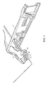
- Figure 1 shows part of the trailing edge of an aircraft wing.
- the wing comprises a front spar 1 which extends along the length of the wing.
- the spar carries a rib 2 with an aft lug 3 and forward lug 4, each lug having a hole 5, 6 passing through it.
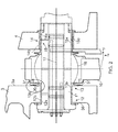
- a landing gear (not shown) is carried on a leg 10 (omitted from Figure 1 but shown in Figure 2 ) and the leg 10 is pivotally mounted to the rib 2 by a pivot joint assembly shown in Figure 2 .
- a pintle 11 passes through the holes in the lugs 3, 4.
- the pintle defines a pivot axis 17 about which the leg 10 rotates.
- An X/Y frame of reference is shown in Figure 2 and 3 , with the Y-axis lying parallel with the pivot axis 17 and the X-axis lying at a right angle to the pivot axis 17 and oriented in the same direction as the leg 10.
- Various bronze bushes provide load-bearing interfaces between the pintle 11 and the lugs 3, 4.
- the bushes are freeze-fitted to the lugs 3,4 so in normal operation they will not rotate relative to the lugs 3,4.
- Two split bushes 12, 13 provide a load-bearing interface between the pintle 11 and the lug 3.
- the bush 12 comprises an annular sleeve with an inner face 12a which engages the pintle 11 and an outer face 12b which engages the bore wall of the hole 5 in the lug 3.
- the bush 13 comprises an annular sleeve with an inner face 13a which engages the pintle 11 and an outer face 13b which engages the bore wall of the hole 5 in the lug 3.
- Two nested bushes 14, 15 provide a load-bearing interface between the pintle 11 and the lug 4.
- the bush 14 comprises an annular sleeve with an inner face 14a which engages the bush 15 and an outer face 14b which engages the bore wall of the hole 6 in the lug 4.
- the bush 15 is nested within the bush 14 and comprises an annular sleeve with an inner face 15a which engages the pintle and an outer face 15b which engages the inner face 14a of the bush 14.
- the landing gear leg 10 is carried by the pintle 11 on a spherical bearing 16 which permits the leg 10 to rotate relative to the pintle 11 about the pivot axis 17 for gear retraction and extension.
- the spherical bearing 16 also provides a degree of freedom for the leg 10 to rotate around the Z-axis (which extends orthogonally to the X and Y axes shown in Figures 2 and 3 ).
- the pintle 11 does not rotate relative to the lugs 3, 4.
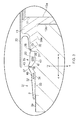
- the bush 13 has a flange 20 which is shown in detail in Figure 3 .
- the flange 20 extends radially away from the sleeve 13a, 13b towards an end face 21.
- the lug 3 has a pair of side walls 3a, 3b on either side.
- the wall 3a is machined with a counterbore with a step 22 and a base 23, and the flange 20 has an inner face 20a which engages the base 23 of the counterbore.
- a dust seal 30 is fitted over the bush 13 and pintle 11 to prevent the ingress of contaminants between them.
- a sealing ring 31 is also provided to prevent the ingress of contaminants such as water, fuel, hydraulic fluid, electrolyte or dust between the bush 13 and the lug 3.
- the sealing ring has an annular body 32 which is bonded to the side wall 3a of the lug 3 outside the counterbore 22, 23 by an adhesive layer 33.
- the body 32 has four annular ribs 34 which ensure that the adhesive layer 33 has a known minimum thickness, and provide an additional barrier to ingress of contaminants.
- the sealing ring 31 also has a sealing member 35 which extends away from the body 32 to a sealing lip 36 which engages the end face 21 of the flange 20 of the bush without being bonded or otherwise attached to it.
- a recess may be provided in the end face 21 to receive the sealing lip 36.
- the sealing member 35 extends away from the body 32 across the step 22, and a gap 39 is present between the sealing member and the base 23 of the counterbore. Note that the sealing member 35 also does not engage the first side wall 3a outside the counterbore so there is a small gap 42 between them.
- the sealing member 35 has a folded portion which is folded to form a ridge 37 on one side and a groove 38 on the other.
- the folded portion enables the sealing member 35 to expand/contract resiliently in the positive/negative radial directions +/-X (i.e. towards/away from the pivot axis 17) in the manner of a bellows or concertina with the ridge 37 and groove 38 becoming progressively flattened as the sealing member expands.
- the folded portion is in a state of resilient compression so that it urges the sealing lip 36 towards the bush and can relax away from the body 32 towards the pintle 11 in the positive radial direction +X to maintain engagement with the bush in the event that the bush distorts (for instance during a hard landing of the aircraft) and in doing so moves away from the body in that positive radial direction +X.
- the sealing member can also bend away the side wall 3a, 23 (in the positive axial direction +Y) or towards the base 23 of the counterbore (in the negative axial direction -Y) to maintain engagement with the bush 13 in the event that the bush distorts (for instance during a hard landing of the aircraft) and in doing so moves relative to the lug in the axial direction.
- the sealing lip 36 is not bonded or otherwise attached to the end face 21, the face 21 can maintain a sliding contact with the sealing lip 36 in the event that it moves in the axial direction. In this case the sealing member is not required to bend towards or away from the side wall to maintain contact.
- the radial expansion/contraction and axial bending motion of the sealing member are assisted by forming a narrow waist at the apex of the ridge 37 with a reduced thickness 43 which acts as a "living hinge".
- the face 21 can maintain a sliding contact with the sealing lip 36 in the event that the bush rotates about the pivot axis 17 so that it moves in a circumferential direction (in or out of the plane of the section of Figure 3 ).
- the body 32 and sealing member 35 are formed by moulding as a single piece.
- the material used to form the body 32 and sealing member 35 is typically an elastomer such as polyurethane rubber or fluorosilicone rubber.
- the adhesive 33 is chosen to form a secure bond and may be for example a polysulphide sealant with a bond strength greater than 3.5MPa.
- the body 32 and sealing member 35 contain metallic or plastic interleaf reinforcement rings 40, 41 on either side of the folded portion 37, 38.
- the ring 40 aids handling of the sealing ring and ensures that flex occurs at the folded portion 37, 38 and thus protects the body 32 from peeling away from the lug 3.
- the ring 41 aids handling and maintains the gap 42 between the sealing member 35 and the wall 3a. This gap 42 prevents the sealing member 35 from catching on the corner where the step 22 meets the wall 3a.
- Figures 4-6 illustrate a preferred method of mounting the sealing ring 31 with an insertion tool.
- the insertion tool has a first part 50 with a bore 54 and an annular flange 51.
- a second part 55 has a rod 56 which is slidably received in the bore 54.
- a spring 57 acts between the parts 50, 55 and is shown in its relaxed position in Figures 4-6 .
- the second part carries a guide piece 60 shown in Figure 4 only.
- the sealing ring 31 is stretched over the guide piece 60 and onto the tool.
- the inner diameter of the ring 31 is less than the outer diameter of the guide piece 60.
- the ring 31 first engages a frustoconical surface 61 of the guide piece 60, and then as it is pushed further the surface 61 forces the inner diameter 31 of the ring to increase evenly by flexure of the folded portion 37, 38.
- the guide piece 60 is then removed leaving the ring in place on the insertion tool as shown in Figure 5 .
- the ring In its installed state the ring is in circumferential tension and compressed radially due to the flexure of the folded portion 37, 38.
- Adhesive is then applied to the annular body 32 of the sealing ring, and the second part 55 of the insertion tool is inserted into the bush 13 as shown in Figure 6 until the flange 53 of the part 55 engages the flange 20 of the bush 13.
- the first part 50 of the insertion tool is then pushed against the force of the spring 57 until the body 32 of the sealing ring is pressed against the wall 3a.
- the first part 50 is then held in place against the spring tension for three hours by a screw clamp (not shown - comprising a large nut and bolt through the assembly) during which time the adhesive cures and the seal is protected.
- the first part 50 is then released which causes it to spring back to the position shown in Figure 6 , leaving the sealing ring adhered in place.
- the insertion tool is then removed.
- Figure 7 is a sectional view of a sealing ring 31a according to a second embodiment of the invention.
- the sealing ring has an annular body 32a which is bonded to the side wall 3a of the lug 3 outside the counterbore 22, 23 by an adhesive layer 33a and to the counterbore 23 by an adhesive layer 39a.
- the body 32a has four annular ribs 34a which ensure that the adhesive layers 33a and 39a have a known minimum thickness.
- the sealing ring 31a has a pair of annular sealing members 37a which extend radially away from the body 32a.
- Each sealing member 37a has a respective sealing lip 36a which engages the end face 21 of the flange 20 of the bush without being attached to it.
- the pair of sealing members 37a are shown in solid lines in their compressed state, and in dashed lines in their relaxed state.
- the sealing members 37a can expand/contract resiliently along their length in the positive/negative radial directions +/-X (i.e. towards/away from the pivot axis 17).
- the sealing members 37a are in a state of resilient compression so that they urge the sealing lips 36a towards the bush and can relax away from the body 32a towards the pintle 11 in the positive radial direction +X to maintain engagement with the bush in the event that the bush distorts (for instance during a hard landing of the aircraft) and in doing so moves away from the body 32a in that positive radial direction +X.
- the sealing members 37a can also bend slightly away the side wall 3a, 23 (in the positive axial direction +Y) or towards the base 23 of the counterbore (in the negative axial direction -Y) to maintain engagement with the bush 13 in the event that the bush distorts (for instance during a hard landing of the aircraft) and in doing so moves relative to the lug in the axial direction, unseating from the counterbore 23.
- the sealing lips 36a are not bonded or otherwise attached to the end face 21, the face 21 can maintain a sliding contact with the sealing lips 36a in the event that it moves in the axial direction. In this case the sealing members 37a are not required to bend towards or away from the side wall 23 to maintain contact.
- the face 21 can maintain a sliding contact with the sealing lips 36a in the event that the bush rotates about the pivot axis 17 so that it moves in a circumferential direction (in or out of the plane of the section).
- the annular body 32a contains a metallic or plastic interleaf reinforcement ring 40a which aids handling of the sealing ring 31a and ensures that flex occurs at the protruding sealing members 37a and thus protects the body 32a from peeling away from the lug 3.
- FIG 8 is a sectional view of a sealing ring 31b according to a third embodiment of the invention.
- the sealing ring 31b is similar to the sealing ring 31a shown in Figure 7 . It has an annular body 32b which is bonded to the side wall 3a of the lug outside the counterbore by an adhesive layer 33b.
- the body 32a has five annular ribs 34b which ensure that the adhesive layer 33b has a known thickness.
- the sealing ring 31b also has a pair of sealing members which extend away from the body 32b to a pair of sealing lips 36b which engage the end face of the flange 20 of the bush without being attached to it.
- a secondary O-ring seal 60 is provided between the flange 20 and the counterbore 23.
- the O-ring 60 is fitted into a groove 61 in the flange 20 and compressed between the flange 20 and the counterbore 23.
Landscapes
- Engineering & Computer Science (AREA)
- General Engineering & Computer Science (AREA)
- Mechanical Engineering (AREA)
- Aviation & Aerospace Engineering (AREA)
- Pivots And Pivotal Connections (AREA)
- Sealing Devices (AREA)
Abstract
Description
- The present invention relates to a pivot joint assembly comprising a first part with first and second side walls and a hole passing through the first part between the side walls, the exterior of the hole being defined by a bore wall; a pivot pin passing through the hole, the pivot pin defining a pivot axis; a second part which is carried by the pivot pin wherein the first or second part can rotate relative to the other part about the pivot axis; a bush comprising an annular sleeve with an inner face which engages the pivot pin and an outer face which engages the bore wall of the first part; and a sealing ring for preventing the ingress of contaminants between the bush and the first part.
- In conventional pivot joints assemblies of this type, the sealing ring comprises a fillet of sealant material such as polysulphide which is applied as a liquid and then allowed to cure so that it adheres to both the bush and the first part via respective adhesive interfaces. A problem with this arrangement is that if the bush moves relative to the first part, then one or both of the adhesive interfaces may fail, permitting the ingress of contaminants between the bush and the first part. This is a particular problem in a joint where the pivot pin is subject to very high loads, such as in a pintle joint of an aircraft landing gear.
- A first aspect of the invention provides a pivot joint assembly according to claim 1. A second aspect of the invention provides a method according to
claim 14. - In a preferred embodiment the sealing member comprises a folded part which forms a ridge between the body portion and the sealing lip and a groove between the ridge and the first side of the wall. The ridge and groove flatten as the sealing member expands towards the pivot axis. Optionally the folded part may comprise two or more ridges and two or more associated grooves (which expand and contract in the manner of a concertina).
- As well as being able to expand axially, preferably the sealing member can also bend away from the first side wall of the first part to maintain engagement with the bush in the event that the bush moves relative to the body in an axial direction parallel with the pivot axis. This may be achieved in a number of ways, for instance:
- by providing the sealing member with a folded part which forms a ridge between the body portion and the sealing lip and a groove between the ridge and the first side of the wall, wherein the ridge and groove flatten as the sealing member expands towards the pivot axis and wherein the folded part can bend away from the first side wall of the first part;
- by providing the sealing member with an elongate shape which can bend along its length; and/or
- by providing the sealing member with a hinge (for instance by forming a narrow waist in the sealing member between the body and the sealing lip).
- Alternatively the sealing member can maintain a sliding contact with the bush to maintain engagement with the bush in the event that the bush moves relative to the body in an axial direction parallel with the pivot axis.
- Preferably the sealing lip can maintain a sliding contact with the bush in the event that the bush moves relative to the body in an axial direction parallel with the pivot axis and/or in a circumferential direction around the pivot axis.
- The sealing member may engage the sleeve of the bush. However more typically the bush has a flange which extends away from the sleeve and the pivot axis towards an end face, the flange engages the first wall of the first part, and the sealing member engages the end face of the flange of the bush without being attached to it.
- Optionally a secondary sealing ring, such as an O-ring, may be provided between the flange and the first wall of the first part.
- In general terms the first or second part can rotate relative to the other part about the pivot axis. This may be achieved in a number of ways including:
- the bush acting as a bearing between the first part and the pivot pin which permits the first part to rotate relative to the pivot pin;
- the bush acting as a bearing between the first part and the pivot pin which permits the pivot pin carrying the second part to rotate relative to the first part;
- providing a bearing (which may optionally be a spherical bearing) between the second part and the pivot pin which permits the second part to rotate on the bearing relative to the pivot pin;
- providing a bearing (which may optionally be a spherical bearing) between the second part and the pivot pin which permits the pivot pin carrying the first part to rotate on the bearing relative to the second part.
- The body of the sealing ring may be attached to the first side wall by fasteners such as bolts or rivets, but more preferably it is bonded to the first side wall. A bonded attachment is more preferred since it can act as a secondary seal. Optionally the body may be both bonded to the first side wall and attached to it by fasteners. The body may be bonded to the first side wall by co-bonding, co-curing, or more preferably by a layer of adhesive (i.e. secondary bonding).
- The sealing member may engage the first side wall but this is not preferred since it will result in an undesirable frictional force between them as the sealing member expands. Therefore preferably a gap is provided between the sealing member and the first side wall.
- Preferably the first side wall is formed with a counterbore with a base and a step; the body portion is attached to the first side wall outside the counterbore; the sealing member extends away from the body across the step; and a gap is present between the sealing member and the base of the counterbore. Preferably the sealing member does not engage the first side wall outside the counterbore.
- Typically the first side wall of the first part faces towards the second part and the second side wall of the first part faces away from the second part. Alternatively the first side wall of the first part (which engages the sealing ring) may face away from the second part.
- Embodiments of the invention will now be described with reference to the accompanying drawings, in which:
-
Figure 1 shows part of the trailing edge of an aircraft wing; -
Figure 2 is a sectional view of a landing gear pintle joint; -
Figure 3 is an enlarged sectional view showing the sealing ring; -
Figure 4 is a perspective view, partly in section, of the sealing ring being mounted on an insertion tool; -
Figure 5 is a perspective view, partly in section, of the sealing ring mounted on the insertion tool with the guide piece removed; -
Figure 6 is a perspective view, partly in section, of the sealing ring being attached to the lug with the insertion tool; -
Figure 7 is a sectional view of a sealing ring according to a second embodiment of the invention; -
Figure 8 is a sectional view of a sealing arrangement according to a third embodiment of the invention. -
Figure 1 shows part of the trailing edge of an aircraft wing. The wing comprises a front spar 1 which extends along the length of the wing. The spar carries a rib 2 with anaft lug 3 andforward lug 4, each lug having ahole 5, 6 passing through it. A landing gear (not shown) is carried on a leg 10 (omitted fromFigure 1 but shown inFigure 2 ) and theleg 10 is pivotally mounted to the rib 2 by a pivot joint assembly shown inFigure 2 . - A
pintle 11 passes through the holes in thelugs pivot axis 17 about which theleg 10 rotates. An X/Y frame of reference is shown inFigure 2 and3 , with the Y-axis lying parallel with thepivot axis 17 and the X-axis lying at a right angle to thepivot axis 17 and oriented in the same direction as theleg 10. - Various bronze bushes provide load-bearing interfaces between the
pintle 11 and thelugs lugs lugs split bushes pintle 11 and thelug 3. Thebush 12 comprises an annular sleeve with aninner face 12a which engages thepintle 11 and anouter face 12b which engages the bore wall of the hole 5 in thelug 3. Similarly thebush 13 comprises an annular sleeve with aninner face 13a which engages thepintle 11 and anouter face 13b which engages the bore wall of the hole 5 in thelug 3. Twonested bushes pintle 11 and thelug 4. Thebush 14 comprises an annular sleeve with aninner face 14a which engages thebush 15 and anouter face 14b which engages the bore wall of thehole 6 in thelug 4. Thebush 15 is nested within thebush 14 and comprises an annular sleeve with aninner face 15a which engages the pintle and anouter face 15b which engages theinner face 14a of thebush 14. - The
landing gear leg 10 is carried by thepintle 11 on aspherical bearing 16 which permits theleg 10 to rotate relative to thepintle 11 about thepivot axis 17 for gear retraction and extension. For misalignments and to stop unwanted load pickup, thespherical bearing 16 also provides a degree of freedom for theleg 10 to rotate around the Z-axis (which extends orthogonally to the X and Y axes shown inFigures 2 and3 ). Thepintle 11 does not rotate relative to thelugs - The
bush 13 has aflange 20 which is shown in detail inFigure 3 . Theflange 20 extends radially away from thesleeve end face 21. Thelug 3 has a pair ofside walls 3a, 3b on either side. Thewall 3a is machined with a counterbore with astep 22 and abase 23, and theflange 20 has aninner face 20a which engages thebase 23 of the counterbore. Adust seal 30 is fitted over thebush 13 andpintle 11 to prevent the ingress of contaminants between them. - A sealing
ring 31 is also provided to prevent the ingress of contaminants such as water, fuel, hydraulic fluid, electrolyte or dust between thebush 13 and thelug 3. The sealing ring has anannular body 32 which is bonded to theside wall 3a of thelug 3 outside thecounterbore adhesive layer 33. Thebody 32 has fourannular ribs 34 which ensure that theadhesive layer 33 has a known minimum thickness, and provide an additional barrier to ingress of contaminants. - The sealing
ring 31 also has a sealingmember 35 which extends away from thebody 32 to a sealinglip 36 which engages theend face 21 of theflange 20 of the bush without being bonded or otherwise attached to it. Optionally a recess may be provided in theend face 21 to receive the sealinglip 36. The sealingmember 35 extends away from thebody 32 across thestep 22, and agap 39 is present between the sealing member and thebase 23 of the counterbore. Note that the sealingmember 35 also does not engage thefirst side wall 3a outside the counterbore so there is asmall gap 42 between them. - The sealing
member 35 has a folded portion which is folded to form a ridge 37 on one side and agroove 38 on the other. The folded portion enables the sealingmember 35 to expand/contract resiliently in the positive/negative radial directions +/-X (i.e. towards/away from the pivot axis 17) in the manner of a bellows or concertina with the ridge 37 andgroove 38 becoming progressively flattened as the sealing member expands. The folded portion is in a state of resilient compression so that it urges the sealinglip 36 towards the bush and can relax away from thebody 32 towards thepintle 11 in the positive radial direction +X to maintain engagement with the bush in the event that the bush distorts (for instance during a hard landing of the aircraft) and in doing so moves away from the body in that positive radial direction +X. - As well as expanding/contracting in the radial direction +/-X, the sealing member can also bend away the
side wall 3a, 23 (in the positive axial direction +Y) or towards thebase 23 of the counterbore (in the negative axial direction -Y) to maintain engagement with thebush 13 in the event that the bush distorts (for instance during a hard landing of the aircraft) and in doing so moves relative to the lug in the axial direction. Alternatively, because the sealinglip 36 is not bonded or otherwise attached to theend face 21, theface 21 can maintain a sliding contact with the sealinglip 36 in the event that it moves in the axial direction. In this case the sealing member is not required to bend towards or away from the side wall to maintain contact. - The radial expansion/contraction and axial bending motion of the sealing member are assisted by forming a narrow waist at the apex of the ridge 37 with a reduced
thickness 43 which acts as a "living hinge". - Furthermore, because the sealing
lip 36 is not bonded or otherwise attached to theend face 21, theface 21 can maintain a sliding contact with the sealinglip 36 in the event that the bush rotates about thepivot axis 17 so that it moves in a circumferential direction (in or out of the plane of the section ofFigure 3 ). - The
body 32 and sealingmember 35 are formed by moulding as a single piece. The material used to form thebody 32 and sealingmember 35 is typically an elastomer such as polyurethane rubber or fluorosilicone rubber. The adhesive 33 is chosen to form a secure bond and may be for example a polysulphide sealant with a bond strength greater than 3.5MPa. - The
body 32 and sealingmember 35 contain metallic or plastic interleaf reinforcement rings 40, 41 on either side of the foldedportion 37, 38. Thering 40 aids handling of the sealing ring and ensures that flex occurs at the foldedportion 37, 38 and thus protects thebody 32 from peeling away from thelug 3. Thering 41 aids handling and maintains thegap 42 between the sealingmember 35 and thewall 3a. Thisgap 42 prevents the sealingmember 35 from catching on the corner where thestep 22 meets thewall 3a. -
Figures 4-6 illustrate a preferred method of mounting the sealingring 31 with an insertion tool. The insertion tool has afirst part 50 with abore 54 and anannular flange 51. Asecond part 55 has arod 56 which is slidably received in thebore 54. Aspring 57 acts between theparts Figures 4-6 . The second part carries aguide piece 60 shown inFigure 4 only. - In a first step shown in
Figure 4 , the sealingring 31 is stretched over theguide piece 60 and onto the tool. In its relaxed state shown inFigure 4 , the inner diameter of thering 31 is less than the outer diameter of theguide piece 60. Thus thering 31 first engages afrustoconical surface 61 of theguide piece 60, and then as it is pushed further thesurface 61 forces theinner diameter 31 of the ring to increase evenly by flexure of the foldedportion 37, 38. Theguide piece 60 is then removed leaving the ring in place on the insertion tool as shown inFigure 5 . In its installed state the ring is in circumferential tension and compressed radially due to the flexure of the foldedportion 37, 38. - Adhesive is then applied to the
annular body 32 of the sealing ring, and thesecond part 55 of the insertion tool is inserted into thebush 13 as shown inFigure 6 until theflange 53 of thepart 55 engages theflange 20 of thebush 13. Thefirst part 50 of the insertion tool is then pushed against the force of thespring 57 until thebody 32 of the sealing ring is pressed against thewall 3a. Thefirst part 50 is then held in place against the spring tension for three hours by a screw clamp (not shown - comprising a large nut and bolt through the assembly) during which time the adhesive cures and the seal is protected. Thefirst part 50 is then released which causes it to spring back to the position shown inFigure 6 , leaving the sealing ring adhered in place. The insertion tool is then removed. -
Figure 7 is a sectional view of asealing ring 31a according to a second embodiment of the invention. The sealing ring has anannular body 32a which is bonded to theside wall 3a of thelug 3 outside thecounterbore adhesive layer 33a and to thecounterbore 23 by anadhesive layer 39a. Thebody 32a has fourannular ribs 34a which ensure that theadhesive layers - The sealing
ring 31a has a pair ofannular sealing members 37a which extend radially away from thebody 32a. Each sealingmember 37a has arespective sealing lip 36a which engages theend face 21 of theflange 20 of the bush without being attached to it. - The pair of sealing
members 37a are shown in solid lines in their compressed state, and in dashed lines in their relaxed state. Thus the sealingmembers 37a can expand/contract resiliently along their length in the positive/negative radial directions +/-X (i.e. towards/away from the pivot axis 17). The sealingmembers 37a are in a state of resilient compression so that they urge the sealinglips 36a towards the bush and can relax away from thebody 32a towards thepintle 11 in the positive radial direction +X to maintain engagement with the bush in the event that the bush distorts (for instance during a hard landing of the aircraft) and in doing so moves away from thebody 32a in that positive radial direction +X. - As well as expanding/contracting in the radial direction +/-X, the sealing
members 37a can also bend slightly away theside wall 3a, 23 (in the positive axial direction +Y) or towards thebase 23 of the counterbore (in the negative axial direction -Y) to maintain engagement with thebush 13 in the event that the bush distorts (for instance during a hard landing of the aircraft) and in doing so moves relative to the lug in the axial direction, unseating from thecounterbore 23. Alternatively, because the sealinglips 36a are not bonded or otherwise attached to theend face 21, theface 21 can maintain a sliding contact with the sealinglips 36a in the event that it moves in the axial direction. In this case the sealingmembers 37a are not required to bend towards or away from theside wall 23 to maintain contact. - Furthermore, because the sealing
lips 36a are not bonded or otherwise attached to theend face 21, theface 21 can maintain a sliding contact with the sealinglips 36a in the event that the bush rotates about thepivot axis 17 so that it moves in a circumferential direction (in or out of the plane of the section). - The
annular body 32a contains a metallic or plasticinterleaf reinforcement ring 40a which aids handling of the sealingring 31a and ensures that flex occurs at the protruding sealingmembers 37a and thus protects thebody 32a from peeling away from thelug 3. -
Figure 8 is a sectional view of asealing ring 31b according to a third embodiment of the invention. The sealingring 31b is similar to thesealing ring 31a shown inFigure 7 . It has anannular body 32b which is bonded to theside wall 3a of the lug outside the counterbore by anadhesive layer 33b. Thebody 32a has fiveannular ribs 34b which ensure that theadhesive layer 33b has a known thickness. The sealingring 31b also has a pair of sealing members which extend away from thebody 32b to a pair of sealinglips 36b which engage the end face of theflange 20 of the bush without being attached to it. - A secondary O-
ring seal 60 is provided between theflange 20 and thecounterbore 23. The O-ring 60 is fitted into agroove 61 in theflange 20 and compressed between theflange 20 and thecounterbore 23. - Although the invention has been described above with reference to one or more preferred embodiments, it will be appreciated that various changes or modifications may be made without departing from the scope of the invention as defined in the appended claims.
Claims (15)
- A pivot joint assembly comprising: a first part with first and second side walls and a hole passing through the first part between the side walls, the exterior of the hole being defined by a bore wall; a pivot pin passing through the hole, the pivot pin defining a pivot axis; a second part which is carried by the pivot pin wherein the first or second part can rotate relative to the other part about the pivot axis; a bush comprising an annular sleeve with an inner face which engages the pivot pin and an outer face which engages the bore wall of the first part; and a sealing ring for preventing the ingress of contaminants between the bush and the first part,
wherein the sealing ring has a body which is attached to the first side wall of the first part, and a sealing member which extends away from the body in a radial direction towards the pivot axis to a sealing lip which engages the bush without being attached to it, and
wherein the sealing member is in a state of resilient compression so that it urges the sealing lip towards the bush and can expand away from the body in the radial direction to maintain engagement with the bush in the event that the bush moves away from the body in the radial direction. - The assembly of claim 1 wherein the sealing member comprises a folded part which forms a ridge between the body portion and the sealing lip and a groove between the ridge and the first side of the wall, wherein the ridge and groove flatten as the sealing member expands towards the pivot axis.
- The assembly of any preceding claim wherein the sealing member can bend away from the first side wall of the first part or maintain a sliding contact with the bush to maintain engagement with the bush in the event that the bush moves relative to the body in an axial direction parallel with the pivot axis.
- The assembly of any preceding claim wherein the sealing lip can maintain a sliding contact with the bush in the event that the bush moves relative to the body in an axial direction parallel with the pivot axis and/or in a circumferential direction around the pivot axis.
- The assembly of any preceding claim wherein the sealing member comprises a hinge which enables the sealing member to bend away from the first side wall of the first part to maintain engagement with the bush in the event that the bush moves relative to the body in an axial direction parallel with the pivot axis.
- The assembly of any preceding claim wherein the bush has a flange which extends away from the sleeve and from the pivot axis towards an end face, the flange engages the first wall of the first part, and the sealing member engages the end face of the flange of the bush without being attached to it.
- The assembly of claim 6 further comprising a secondary sealing ring which is compressed between the flange and the first wall of the first part.
- The assembly of any preceding claim further comprising a bearing between the second part and the pivot pin which permits the second part to rotate on the bearing about the pivot pin.
- The assembly of any preceding claim wherein the body is bonded to the first side wall.
- The assembly of claim 9 wherein the body is bonded to the first side wall by a layer of adhesive.
- The assembly of any preceding claim wherein the first side wall is formed with a counterbore with a base and a step; the body portion is attached to the first side wall outside the counterbore; the sealing member extends away from the body across the step; and a gap is present between the sealing member and the base of the counterbore.
- The assembly of claim 11 wherein the sealing member does not engage the first side wall outside the counterbore.
- The assembly of any preceding claim wherein the first side wall of the first part faces towards the second part and the second side wall of the first part faces away from the second part.
- A method of assembling a pivot joint assembly, the method comprising:a. providing a first part with first and second side walls and a hole passing through the first part between the side walls, the exterior of the hole being defined by a bore wall;b. passing a pivot pin through the hole, the pivot pin defining a pivot axis;c. providing a second part which is carried by the pivot pin wherein the first or second part can rotate relative to the other part about the pivot axis;d. providing a bush comprising an annular sleeve with an inner face which engages the pivot pin and an outer face which engages the bore wall of the first part; ande. attaching a body of a sealing ring to the first side wall of the first part, the sealing member comprising a sealing member which extends away from the body in a radial direction towards the pivot axis to a sealing lip which engages the bush without being attached to it; andf. placing the sealing member in a state of resilient compression so that it urges the sealing lip towards the bush and can expand away from the body in the radial direction to maintain engagement with the bush in the event that the bush moves away from the body in the radial direction.
- The method of claim 14 wherein the sealing member is placed in a state of resilient compression by stretching it over an insertion tool before step e); and wherein the body of the sealing ring is attached to the first side wall in step e) by pressing the body of the sealing ring onto the first side wall with the insertion tool.
Applications Claiming Priority (1)
| Application Number | Priority Date | Filing Date | Title |
|---|---|---|---|
| GBGB1110483.3A GB201110483D0 (en) | 2011-06-21 | 2011-06-21 | Pivot joint assembly |
Publications (2)
| Publication Number | Publication Date |
|---|---|
| EP2538096A2 true EP2538096A2 (en) | 2012-12-26 |
| EP2538096A3 EP2538096A3 (en) | 2016-11-16 |
Family
ID=44454400
Family Applications (1)
| Application Number | Title | Priority Date | Filing Date |
|---|---|---|---|
| EP12171450.5A Withdrawn EP2538096A3 (en) | 2011-06-21 | 2012-06-11 | Pivot joint assembly |
Country Status (3)
| Country | Link |
|---|---|
| US (1) | US8893368B2 (en) |
| EP (1) | EP2538096A3 (en) |
| GB (1) | GB201110483D0 (en) |
Cited By (2)
| Publication number | Priority date | Publication date | Assignee | Title |
|---|---|---|---|---|
| CN112173084A (en) * | 2020-09-25 | 2021-01-05 | 中国直升机设计研究所 | Retractable main landing gear bearing structure of unmanned high-speed helicopter and design method thereof |
| GB2638554A (en) * | 2024-01-31 | 2025-08-27 | Skf Aerospace France Sas | Fixing assembly comprising a clevis and a tang |
Families Citing this family (5)
| Publication number | Priority date | Publication date | Assignee | Title |
|---|---|---|---|---|
| US20150314805A1 (en) * | 2014-05-05 | 2015-11-05 | GM Global Technology Operations LLC | Coupling assembly and a method of decoupling a first member and a second member |
| FR3021373B1 (en) * | 2014-05-21 | 2016-12-09 | Snecma | JOINT HINGE DEVICE FOR A TURBOMACHINE. |
| EP3059163B1 (en) * | 2015-02-18 | 2019-06-19 | Safran Landing Systems UK Limited | Aircraft assembly |
| CN206765730U (en) | 2017-02-24 | 2017-12-19 | 浙江春风动力股份有限公司 | A kind of beach buggy and its rear arm bearing Mounting device |
| CN118723067B (en) * | 2024-07-30 | 2025-10-10 | 东方蓝天钛金科技有限公司 | Main landing gear emergency disconnection safety device |
Family Cites Families (27)
| Publication number | Priority date | Publication date | Assignee | Title |
|---|---|---|---|---|
| US2747817A (en) * | 1953-08-11 | 1956-05-29 | Saulnier Raymond | Retractable landing gears |
| DE1956147U (en) * | 1963-07-27 | 1967-02-23 | Eisenwerk Rothe Erde G M B H | DEVICE FOR FASTENING RUBBER RING SEAL OD. DGL. FOR LARGE BEARINGS. |
| FR1595108A (en) * | 1968-12-13 | 1970-06-08 | ||
| JPS50140752A (en) * | 1974-04-21 | 1975-11-12 | ||
| JPS5539178Y2 (en) * | 1976-06-22 | 1980-09-12 | ||
| GB8722021D0 (en) * | 1987-09-18 | 1987-10-28 | British Aerospace | Lock nut assemblies |
| JP3261275B2 (en) * | 1994-12-28 | 2002-02-25 | エヌオーケー株式会社 | Sealing device |
| US6016995A (en) * | 1997-08-26 | 2000-01-25 | The Boeing Company | Aircraft nose landing gear |
| FR2793210B1 (en) * | 1999-05-05 | 2001-09-21 | Aerospatiale Airbus | STRUCTURE FOR ATTACHING A LANDING GEAR TO AN AIRCRAFT FUSELAGE |
| FR2796686B1 (en) * | 1999-07-19 | 2001-12-07 | Gkn Glaenzer Spicer | BELLOWS AND CORRESPONDING TRANSMISSION JOINT |
| FR2796684B1 (en) * | 1999-07-19 | 2001-10-12 | Gkn Glaenzer Spicer | TRANSMISSION JOINT |
| JP4079633B2 (en) * | 2001-12-05 | 2008-04-23 | 株式会社ショーワ | Structure for preventing intrusion of water etc. in universal joint boots |
| FR2840585B1 (en) * | 2002-06-10 | 2005-02-04 | Airbus France | DEVICE FOR MOUNTING A LANDING TRAIN ON AN AIRCRAFT STRUCTURE |
| US6938902B2 (en) * | 2003-02-26 | 2005-09-06 | Delphi Technologies, Inc. | Boot with O-ring seal |
| JP4918258B2 (en) * | 2003-05-02 | 2012-04-18 | 株式会社小松製作所 | Bearing seal and rotating device |
| US7798497B2 (en) * | 2007-03-19 | 2010-09-21 | Freudenberg-Nok General Partnership | Tight package sensor seal |
| US8002287B2 (en) * | 2004-02-09 | 2011-08-23 | Freudenberg-Nok General Partnership | Hand assemblable fuel injector seal |
| US20050173869A1 (en) * | 2004-02-09 | 2005-08-11 | Freudenberg-Nok General Partnership | Spark plug tube seal |
| US7367739B2 (en) * | 2004-08-02 | 2008-05-06 | Clark Equipment Company | Two component seal |
| JP2006161969A (en) | 2004-12-08 | 2006-06-22 | Toyota Industries Corp | Bearing portion sealing method and its device |
| WO2006081393A2 (en) * | 2005-01-26 | 2006-08-03 | Gkn Driveline North America, Inc. | Boot for a joint |
| WO2006081664A1 (en) * | 2005-02-03 | 2006-08-10 | Héroux-Devtek Inc. | Alternative uplock release assembly |
| DE102006028276B4 (en) * | 2005-06-21 | 2018-01-04 | Kaco Gmbh + Co. Kg | Sealing ring, and method for producing such a sealing ring |
| US7861535B2 (en) * | 2007-09-24 | 2011-01-04 | United Technologies Corporation | Self-aligning liner support hanger |
| US8157657B2 (en) * | 2007-12-19 | 2012-04-17 | Gkn Driveline North America, Inc. | Selectively expandable and contractible barrier |
| EP2288819B1 (en) * | 2008-06-27 | 2014-10-08 | GKN Driveline International GmbH | system consisting of a housing and a rolling boot |
| ATE544675T1 (en) * | 2009-11-04 | 2012-02-15 | Agustawestland Spa | LANDING POWER FOR AN AIRCRAFT |
-
2011
- 2011-06-21 GB GBGB1110483.3A patent/GB201110483D0/en not_active Ceased
-
2012
- 2012-06-11 EP EP12171450.5A patent/EP2538096A3/en not_active Withdrawn
- 2012-06-18 US US13/525,459 patent/US8893368B2/en active Active
Non-Patent Citations (1)
| Title |
|---|
| None |
Cited By (3)
| Publication number | Priority date | Publication date | Assignee | Title |
|---|---|---|---|---|
| CN112173084A (en) * | 2020-09-25 | 2021-01-05 | 中国直升机设计研究所 | Retractable main landing gear bearing structure of unmanned high-speed helicopter and design method thereof |
| CN112173084B (en) * | 2020-09-25 | 2023-04-07 | 中国直升机设计研究所 | Retractable main landing gear bearing structure of unmanned high-speed helicopter and design method thereof |
| GB2638554A (en) * | 2024-01-31 | 2025-08-27 | Skf Aerospace France Sas | Fixing assembly comprising a clevis and a tang |
Also Published As
| Publication number | Publication date |
|---|---|
| US20120324707A1 (en) | 2012-12-27 |
| US8893368B2 (en) | 2014-11-25 |
| EP2538096A3 (en) | 2016-11-16 |
| GB201110483D0 (en) | 2011-08-03 |
Similar Documents
| Publication | Publication Date | Title |
|---|---|---|
| US8893368B2 (en) | Pivot joint assembly | |
| US5915842A (en) | Elastomeric bearing and assembly method therefor | |
| JP6854691B2 (en) | Seal assembly for sealing relatively movable components | |
| US9863464B2 (en) | Dust cover | |
| US20120241560A1 (en) | Joint Sealing System | |
| EP2812248B1 (en) | Connecting arrangement and method for providing such connecting arrangement | |
| US10077843B2 (en) | Division type mechanical seal | |
| CN109383743B (en) | Pressure diaphragm system | |
| CN108368870B (en) | Dust cover and seal structure | |
| EP2518340A1 (en) | Fay surface sealant application | |
| EP2037147B1 (en) | Friction damper | |
| CN105102834A (en) | Sleeve seal and method for a machine system | |
| US9856910B2 (en) | Self-lubricated thrust bearing for a hinged aircraft wing | |
| EP2844883B1 (en) | Bush assembly | |
| US20180003254A1 (en) | Adapter for an Isolation Mount Design | |
| US20200378423A1 (en) | Hybrid metallic/composite joint with enhanced strength | |
| RU2556266C2 (en) | Bearing assembly (versions) and method of bearing mounting in casing (versions) | |
| CN206738566U (en) | static seal | |
| US7775770B2 (en) | Pitch bearing containment seal | |
| JP4820227B2 (en) | Connecting member and joint | |
| JP6735421B2 (en) | Ball joint | |
| US12479562B2 (en) | Flexible corner fitting intended to contribute to a connection between at least three walls of at least one aircraft box structure | |
| KR20210097697A (en) | bellows | |
| US10584745B2 (en) | Asymmetric bearing for riser tensioner system | |
| US20250083792A1 (en) | Circumferential skin joints for aerospace structures, methods of assembling the joints, and methods of manufacturing fuselage members that define the joints |
Legal Events
| Date | Code | Title | Description |
|---|---|---|---|
| PUAI | Public reference made under article 153(3) epc to a published international application that has entered the european phase |
Free format text: ORIGINAL CODE: 0009012 |
|
| AK | Designated contracting states |
Kind code of ref document: A2 Designated state(s): AL AT BE BG CH CY CZ DE DK EE ES FI FR GB GR HR HU IE IS IT LI LT LU LV MC MK MT NL NO PL PT RO RS SE SI SK SM TR |
|
| AX | Request for extension of the european patent |
Extension state: BA ME |
|
| PUAL | Search report despatched |
Free format text: ORIGINAL CODE: 0009013 |
|
| AK | Designated contracting states |
Kind code of ref document: A3 Designated state(s): AL AT BE BG CH CY CZ DE DK EE ES FI FR GB GR HR HU IE IS IT LI LT LU LV MC MK MT NL NO PL PT RO RS SE SI SK SM TR |
|
| AX | Request for extension of the european patent |
Extension state: BA ME |
|
| RIC1 | Information provided on ipc code assigned before grant |
Ipc: F16C 11/06 20060101AFI20161013BHEP |
|
| STAA | Information on the status of an ep patent application or granted ep patent |
Free format text: STATUS: THE APPLICATION IS DEEMED TO BE WITHDRAWN |
|
| 18D | Application deemed to be withdrawn |
Effective date: 20170517 |