EP2538025A1 - Hot gas path component and corresponding method of forming a component - Google Patents
Hot gas path component and corresponding method of forming a component Download PDFInfo
- Publication number
- EP2538025A1 EP2538025A1 EP12172488A EP12172488A EP2538025A1 EP 2538025 A1 EP2538025 A1 EP 2538025A1 EP 12172488 A EP12172488 A EP 12172488A EP 12172488 A EP12172488 A EP 12172488A EP 2538025 A1 EP2538025 A1 EP 2538025A1
- Authority
- EP
- European Patent Office
- Prior art keywords
- pin
- film
- fins
- gas path
- hot gas
- Prior art date
- Legal status (The legal status is an assumption and is not a legal conclusion. Google has not performed a legal analysis and makes no representation as to the accuracy of the status listed.)
- Granted
Links
Images

Classifications
-
- F—MECHANICAL ENGINEERING; LIGHTING; HEATING; WEAPONS; BLASTING
- F01—MACHINES OR ENGINES IN GENERAL; ENGINE PLANTS IN GENERAL; STEAM ENGINES
- F01D—NON-POSITIVE DISPLACEMENT MACHINES OR ENGINES, e.g. STEAM TURBINES
- F01D5/00—Blades; Blade-carrying members; Heating, heat-insulating, cooling or antivibration means on the blades or the members
- F01D5/12—Blades
- F01D5/14—Form or construction
- F01D5/18—Hollow blades, i.e. blades with cooling or heating channels or cavities; Heating, heat-insulating or cooling means on blades
- F01D5/187—Convection cooling
-
- F—MECHANICAL ENGINEERING; LIGHTING; HEATING; WEAPONS; BLASTING
- F05—INDEXING SCHEMES RELATING TO ENGINES OR PUMPS IN VARIOUS SUBCLASSES OF CLASSES F01-F04
- F05D—INDEXING SCHEME FOR ASPECTS RELATING TO NON-POSITIVE-DISPLACEMENT MACHINES OR ENGINES, GAS-TURBINES OR JET-PROPULSION PLANTS
- F05D2240/00—Components
- F05D2240/80—Platforms for stationary or moving blades
- F05D2240/81—Cooled platforms
-
- F—MECHANICAL ENGINEERING; LIGHTING; HEATING; WEAPONS; BLASTING
- F05—INDEXING SCHEMES RELATING TO ENGINES OR PUMPS IN VARIOUS SUBCLASSES OF CLASSES F01-F04
- F05D—INDEXING SCHEME FOR ASPECTS RELATING TO NON-POSITIVE-DISPLACEMENT MACHINES OR ENGINES, GAS-TURBINES OR JET-PROPULSION PLANTS
- F05D2260/00—Function
- F05D2260/20—Heat transfer, e.g. cooling
- F05D2260/202—Heat transfer, e.g. cooling by film cooling
-
- F—MECHANICAL ENGINEERING; LIGHTING; HEATING; WEAPONS; BLASTING
- F05—INDEXING SCHEMES RELATING TO ENGINES OR PUMPS IN VARIOUS SUBCLASSES OF CLASSES F01-F04
- F05D—INDEXING SCHEME FOR ASPECTS RELATING TO NON-POSITIVE-DISPLACEMENT MACHINES OR ENGINES, GAS-TURBINES OR JET-PROPULSION PLANTS
- F05D2260/00—Function
- F05D2260/20—Heat transfer, e.g. cooling
- F05D2260/221—Improvement of heat transfer
- F05D2260/2214—Improvement of heat transfer by increasing the heat transfer surface
- F05D2260/22141—Improvement of heat transfer by increasing the heat transfer surface using fins or ribs
Definitions
- the subject matter disclosed herein relates to a turbine engine airfoil and, more particularly, to a turbine engine airfoil with a pin-bank alignment for film- cooling design.
- a hot gas path component includes a body having a surface and being formed to define a cavity, the cavity employing coolant flow through a pin-fm bank with coolant discharge through film-cooling holes defined on the surface, the pin-fin bank including first and second pluralities of pin-fins, the first plurality of pin-fins and the second plurality of pin-fins each being aligned with a determined flow streamline, and any two pin-fins of the first and second pluralities of pin-fins being separated from one another by a gap as a function of a film-cooling hole dimension.
- a gas turbine including the above hot gas path component and wherein the body comprises an airfoil end wall structure
- a method of forming a hot gas path component includes modeling the hot gas path component, determining a flow streamline along a surface of the modeled hot gas path component and casting the modeled hot gas path component with a pin-fin bank including first and second pluralities of pin-fins, the first plurality of pin-fins and the second plurality of pin-fins each being aligned with the determined flow streamline.
- a hot gas path component 10 is provided.
- the hot gas path component 10 includes a body 20 having a surface 21.
- the body 20 is formed to define a cavity 30 therein.
- the cavity 30 employs coolant flow to cool the body 20 through a pin-fm bank 40 with coolant discharge to the surface 21 being permitted through film-cooling holes 50.
- the film-cooling holes 50 are defined on the surface 21 between individual pin-fins 55 of the pin-fm bank 40.
- the film-cooling holes 50 are defined on the surface 21 at a predefmed film-hole centerline that provides the best cooling benefit, based on analysis, for topography of a given surface 21. Since optimal film-hole centerline locations would not be known, after the body 20 is formed (i.e., cast), it is necessary to provide space between the individual pin-fins 55 of the pin-fm bank 40 during the forming process.
- the film-cooling holes 50 can then be formed at a later time once the predefined film-hole centerline is ascertained in the space between the individual pin-fins 55. This later forming of the film-cooling holes 50 allows for tunable film cooling based on engine/test data without requiring, for example, a casting change and provides for relatively non-restricted film-cooling hole locations.
- the pin-fm bank 40 includes at least a first plurality of pin-fins 60 and a second plurality of pin-fins 70.
- the first plurality of pin-fins 60 and the second plurality of pin-fins 70 are each substantially and respectively aligned in parallel with a determined flow streamline 80, which describes an external gas flow velocity vector and which is known at a time the body 20 is formed.
- Any two individual pin-fins 55 of the first and/or the second pluralities of pin-fins 60, 70 are separated from one another by at least a gap, G.
- the gap, G is determined as a function of at least a dimension of one or more of the film-cooling holes 50 in a direction substantially perpendicular to the determined flow streamline 80.
- the surface 21 may include a surface of an airfoil end wall structure of a gas turbine engine with the first plurality of pin-fins 60 being arranged proximate to an edge 90 of an airfoil footprint on an end wall and the second plurality of pin-fins 70 being arranged on a side of the first plurality of pin-fins 60 facing away from the edge 90.
- the pin-fm bank 40 may further include additional pluralities of pin-fins, such as third plurality of pin-fins 100 and fourth plurality of pin-fins 110.
- the pin-fin bank 40 may include a first set of pin-fins 120 and a second set of pin-fins 130, which are separated from one another by a predefined distance that is at least as large as the gap, G, along the determined flow streamline 80.
- the gap, G is determined as a function of at least the dimension of one or more of the film-cooling holes 50 and at least one or more of the true position of the individual pin-fins 55 and film-cooling holes 50.
- the film-cooling holes 50 may have polygonal, trapezoidal, elliptical or other similar shapes.
- the dimensions of the one or more of the film-cooling holes 50 by which the gap, G, is determined may be a film-cooling hole diameter.
- a film-cooling hole diffuser spread angle may be provided to cover pin-fin widths. This allows for potential film-cooling of any portion of the pin-fin bank 40 as needed without requiring, for example, a casting change.
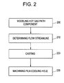
- a method of forming a hot gas path component 10 includes modeling 200 a shape of the hot gas path component 10, determining 210 the flow streamline 80 along the surface 21 of the modeled hot gas path component 10, and casting 220 the modeled hot gas path component 10.
- the casting 220 includes casting of the pin-fin bank 40 including first and second pluralities of pin-fins 60, 70, where the first plurality of pin-fins 60 and the second plurality of pin-fins 70 are each substantially and respectively aligned with the determined flow streamline 80.
- the casting 220 may include separating any two individual pin-fins 55 of the first and second pluralities of pin-fms 60, 70 by a gap, G, as a function of a film-cooling hole dimension where the film-cooling hole dimension may be a film-cooling hole diameter.
- the method further includes machining 230 a film-cooling hole 50 at a predefined position wherein the machining may include, for example, machining the film-cooling hole 50 to have a polygonal, trapezoidal shape, an elliptical shape or another similar shape.
Landscapes
- Engineering & Computer Science (AREA)
- Mechanical Engineering (AREA)
- General Engineering & Computer Science (AREA)
- Turbine Rotor Nozzle Sealing (AREA)
Abstract
Description
- The subject matter disclosed herein relates to a turbine engine airfoil and, more particularly, to a turbine engine airfoil with a pin-bank alignment for film- cooling design.
- The current usage of pin-fms and film-cooling holes in gas turbine component cooling, especially in complex end-wall cooling configurations, is not provided so that film-cooling can be most effective for a given arbitrarily arranged pin-fm structure in a typically cast cavity of a gas path component. As such, it is difficult to place film-cooling holes on the hot surface of the gas path component due to film-cooling hole drilling restrictions for existing pin-fin arrays in the underlying coolant cavity. Thus, film-cooling holes are typically drilled at locations where they do not interfere with the pin-fm structure but do not necessarily provide for the most efficient film-cooling. Therefore, film effectiveness on the hot-surface is often non-optimal for given gasflow conditions.
- According to one aspect of the invention, a hot gas path component is provided and includes a body having a surface and being formed to define a cavity, the cavity employing coolant flow through a pin-fm bank with coolant discharge through film-cooling holes defined on the surface, the pin-fin bank including first and second pluralities of pin-fins, the first plurality of pin-fins and the second plurality of pin-fins each being aligned with a determined flow streamline, and any two pin-fins of the first and second pluralities of pin-fins being separated from one another by a gap as a function of a film-cooling hole dimension.
- According to another aspect of the invention, a gas turbine is provided including the above hot gas path component and wherein the body comprises an airfoil end wall structure
- According to another aspect of the invention, a method of forming a hot gas path component is provided and includes modeling the hot gas path component, determining a flow streamline along a surface of the modeled hot gas path component and casting the modeled hot gas path component with a pin-fin bank including first and second pluralities of pin-fins, the first plurality of pin-fins and the second plurality of pin-fins each being aligned with the determined flow streamline.
- These and other advantages and features will become more apparent from the following description taken in conjunction with the drawings.
- Embodiments of the present invention will now be described, by way of example only, with reference to the accompanying drawings in which:
-
FIG. 1 is a schematic view of a hot gas path component; and -
FIG. 2 is a flow diagram illustrating a method of forming a hot gas path component. - The detailed description explains embodiments of the invention, together with advantages and features, by way of example with reference to the drawings.
- With reference to
FIG. 1 , a hotgas path component 10 is provided. The hotgas path component 10 includes abody 20 having asurface 21. Thebody 20 is formed to define acavity 30 therein. Thecavity 30 employs coolant flow to cool thebody 20 through a pin-fm bank 40 with coolant discharge to thesurface 21 being permitted through film-cooling holes 50. The film-cooling holes 50 are defined on thesurface 21 between individual pin-fins 55 of the pin-fm bank 40. - In particular, the film-
cooling holes 50 are defined on thesurface 21 at a predefmed film-hole centerline that provides the best cooling benefit, based on analysis, for topography of a givensurface 21. Since optimal film-hole centerline locations would not be known, after thebody 20 is formed (i.e., cast), it is necessary to provide space between the individual pin-fins 55 of the pin-fm bank 40 during the forming process. - The film-
cooling holes 50 can then be formed at a later time once the predefined film-hole centerline is ascertained in the space between the individual pin-fins 55. This later forming of the film-cooling holes 50 allows for tunable film cooling based on engine/test data without requiring, for example, a casting change and provides for relatively non-restricted film-cooling hole locations. - The pin-
fm bank 40 includes at least a first plurality of pin-fins 60 and a second plurality of pin-fins 70. The first plurality of pin-fins 60 and the second plurality of pin-fins 70 are each substantially and respectively aligned in parallel with adetermined flow streamline 80, which describes an external gas flow velocity vector and which is known at a time thebody 20 is formed. Any two individual pin-fins 55 of the first and/or the second pluralities of pin-fins cooling holes 50 in a direction substantially perpendicular to thedetermined flow streamline 80. - The
surface 21 may include a surface of an airfoil end wall structure of a gas turbine engine with the first plurality of pin-fins 60 being arranged proximate to anedge 90 of an airfoil footprint on an end wall and the second plurality of pin-fins 70 being arranged on a side of the first plurality of pin-fins 60 facing away from theedge 90. The pin-fm bank 40 may further include additional pluralities of pin-fins, such as third plurality of pin-fins 100 and fourth plurality of pin-fins 110. In addition, the pin-fin bank 40 may include a first set of pin-fins 120 and a second set of pin-fins 130, which are separated from one another by a predefined distance that is at least as large as the gap, G, along thedetermined flow streamline 80. - The gap, G, is determined as a function of at least the dimension of one or more of the film-
cooling holes 50 and at least one or more of the true position of the individual pin-fins 55 and film-cooling holes 50. The film-cooling holes 50 may have polygonal, trapezoidal, elliptical or other similar shapes. The dimensions of the one or more of the film-cooling holes 50 by which the gap, G, is determined may be a film-cooling hole diameter. Also, a film-cooling hole diffuser spread angle may be provided to cover pin-fin widths. This allows for potential film-cooling of any portion of the pin-fin bank 40 as needed without requiring, for example, a casting change. - With reference to
FIG. 2 , a method of forming a hotgas path component 10 is provided. The method includes modeling 200 a shape of the hotgas path component 10, determining 210 theflow streamline 80 along thesurface 21 of the modeled hotgas path component 10, and casting 220 the modeled hotgas path component 10. Thecasting 220 includes casting of the pin-fin bank 40 including first and second pluralities of pin-fins fins 60 and the second plurality of pin-fins 70 are each substantially and respectively aligned with thedetermined flow streamline 80. Thecasting 220 may include separating any two individual pin-fins 55 of the first and second pluralities of pin-fms - Once the casting is complete, the alignment of the pin-
fin bank 40 and the separation between individual pin-fins 55 allows for the tunable film cooling based on engine/test data without requiring, for example, casting changes and provides for relatively non-restricted film-cooling hole locations. As such, the method further includes machining 230 a film-cooling hole 50 at a predefined position wherein the machining may include, for example, machining the film-cooling hole 50 to have a polygonal, trapezoidal shape, an elliptical shape or another similar shape. - While the invention has been described in detail in connection with only a limited number of embodiments, it should be readily understood that the invention is not limited to such disclosed embodiments. Rather, the invention can be modified to incorporate any number of variations, alterations, substitutions or equivalent arrangements not heretofore described, but which are commensurate with the spirit and scope of the invention. Additionally, while various embodiments of the invention have been described, it is to be understood that aspects of the invention may include only some of the described embodiments. Accordingly, the invention is not to be seen as limited by the foregoing description, but is only limited by the scope of the appended claims.
Claims (12)
- A hot gas path component (10), comprising:a body (20) having a surface (21) and being formed to define a cavity (30), the cavity (30) employing coolant flow through a pin-fin bank (40) with coolant discharge through film-cooling holes (50) defined on the surface (21),the pin-fin bank (40) including first and second pluralities of pin-fins (60, 70), the first plurality of pin-fins (60) and the second plurality of pin-fins (70) each being aligned with a determined flow streamline (80), andany two pin-fins of the first and second pluralities of pin-fins (60, 70) being separated from one another by a gap as a function of a film-cooling hole (50) dimension.
- The hot gas path component (10) according to claim 1, wherein the surface (21) comprises a surface of an airfoil end wall structure.
- The hot gas path component (10) according to claim 1 or 2, wherein the film-cooling hole (50) dimension is a film-cooling hole diameter.
- The hot gas path component (10) according to claim 1 or 2, wherein the film-cooling hole (50) has a polygonal shape.
- The hot gas path component (10) according to claim 1 or 2, wherein the film-cooling hole (50) has an elliptical shape.
- A gas turbine engine, comprising the hot gas path component of any of claims 1 to 5, wherein the body (20) comprises an airfoil end wall structure.
- A method of forming a hot gas path component (10), comprising:modeling the hot gas path component (200);determining a flow streamline along a surface of the modeled hot gas path component (210); andcasting the modeled hot gas path component with a pin-fin bank including first and second pluralities of pin-fins (220), the first plurality of pin-fins and the second plurality of pin-fins each being aligned with the determined flow streamline.
- The method according to claim 7, wherein the casting comprises separating any two pin-fins (220) of the first and second pluralities of pin-fins (220) by a gap as a function of a film-cooling hole (50) dimension.
- The method according to claim 8, wherein the film-cooling hole dimension is a film-cooling hole diameter.
- The method according to any of claims 7 to 9, further comprising machining a film-cooling hole (50).
- The method according to claim 10, wherein the machining comprises machining the film-cooling hole (50) to have a polygonal shape.
- The method according to claim 10, wherein the machining comprises machining the film-cooling hole (50) to have an elliptical shape.
Applications Claiming Priority (1)
| Application Number | Priority Date | Filing Date | Title |
|---|---|---|---|
| US13/164,113 US8915712B2 (en) | 2011-06-20 | 2011-06-20 | Hot gas path component |
Publications (2)
| Publication Number | Publication Date |
|---|---|
| EP2538025A1 true EP2538025A1 (en) | 2012-12-26 |
| EP2538025B1 EP2538025B1 (en) | 2018-08-08 |
Family
ID=46354033
Family Applications (1)
| Application Number | Title | Priority Date | Filing Date |
|---|---|---|---|
| EP12172488.4A Active EP2538025B1 (en) | 2011-06-20 | 2012-06-18 | Hot gas path component and corresponding method of forming a component |
Country Status (3)
| Country | Link |
|---|---|
| US (1) | US8915712B2 (en) |
| EP (1) | EP2538025B1 (en) |
| CN (1) | CN102839991B (en) |
Families Citing this family (2)
| Publication number | Priority date | Publication date | Assignee | Title |
|---|---|---|---|---|
| US10598382B2 (en) | 2014-11-07 | 2020-03-24 | United Technologies Corporation | Impingement film-cooled floatwall with backside feature |
| US10370983B2 (en) | 2017-07-28 | 2019-08-06 | Rolls-Royce Corporation | Endwall cooling system |
Citations (5)
| Publication number | Priority date | Publication date | Assignee | Title |
|---|---|---|---|---|
| US3800864A (en) * | 1972-09-05 | 1974-04-02 | Gen Electric | Pin-fin cooling system |
| US5413458A (en) * | 1994-03-29 | 1995-05-09 | United Technologies Corporation | Turbine vane with a platform cavity having a double feed for cooling fluid |
| EP1074696A2 (en) * | 1999-08-02 | 2001-02-07 | United Technologies Corporation | Stator vane for a rotary machine |
| EP1726785A2 (en) * | 2005-05-23 | 2006-11-29 | United Technologies Corporation | Turbine airfoil platform cooling circuit |
| EP2469034A2 (en) * | 2010-12-22 | 2012-06-27 | United Technologies Corporation | Turbine stator vane having a platform with a cooling circuit and corresponding manufacturing method |
Family Cites Families (16)
| Publication number | Priority date | Publication date | Assignee | Title |
|---|---|---|---|---|
| GB1550368A (en) * | 1975-07-16 | 1979-08-15 | Rolls Royce | Laminated materials |
| US5197852A (en) | 1990-05-31 | 1993-03-30 | General Electric Company | Nozzle band overhang cooling |
| US5382135A (en) * | 1992-11-24 | 1995-01-17 | United Technologies Corporation | Rotor blade with cooled integral platform |
| ES2144147T3 (en) | 1994-11-10 | 2000-06-01 | Siemens Westinghouse Power | GAS TURBINE ALABE WITH REFRIGERATED INTERNAL JAM. |
| US6243948B1 (en) * | 1999-11-18 | 2001-06-12 | General Electric Company | Modification and repair of film cooling holes in gas turbine engine components |
| EP1188902A1 (en) * | 2000-09-14 | 2002-03-20 | Siemens Aktiengesellschaft | Impingement cooled wall |
| US6974308B2 (en) * | 2001-11-14 | 2005-12-13 | Honeywell International, Inc. | High effectiveness cooled turbine vane or blade |
| JP4191578B2 (en) * | 2003-11-21 | 2008-12-03 | 三菱重工業株式会社 | Turbine cooling blade of gas turbine engine |
| JP4931157B2 (en) * | 2006-02-14 | 2012-05-16 | 株式会社Ihi | Cooling structure |
| US7695247B1 (en) * | 2006-09-01 | 2010-04-13 | Florida Turbine Technologies, Inc. | Turbine blade platform with near-wall cooling |
| US7690894B1 (en) * | 2006-09-25 | 2010-04-06 | Florida Turbine Technologies, Inc. | Ceramic core assembly for serpentine flow circuit in a turbine blade |
| US7862291B2 (en) * | 2007-02-08 | 2011-01-04 | United Technologies Corporation | Gas turbine engine component cooling scheme |
| US7901182B2 (en) * | 2007-05-18 | 2011-03-08 | Siemens Energy, Inc. | Near wall cooling for a highly tapered turbine blade |
| JP2009162119A (en) * | 2008-01-08 | 2009-07-23 | Ihi Corp | Turbine blade cooling structure |
| US7901183B1 (en) * | 2008-01-22 | 2011-03-08 | Florida Turbine Technologies, Inc. | Turbine blade with dual aft flowing triple pass serpentines |
| US8109735B2 (en) * | 2008-11-13 | 2012-02-07 | Honeywell International Inc. | Cooled component with a featured surface and related manufacturing method |
-
2011
- 2011-06-20 US US13/164,113 patent/US8915712B2/en active Active
-
2012
- 2012-06-18 EP EP12172488.4A patent/EP2538025B1/en active Active
- 2012-06-20 CN CN201210204788.9A patent/CN102839991B/en active Active
Patent Citations (5)
| Publication number | Priority date | Publication date | Assignee | Title |
|---|---|---|---|---|
| US3800864A (en) * | 1972-09-05 | 1974-04-02 | Gen Electric | Pin-fin cooling system |
| US5413458A (en) * | 1994-03-29 | 1995-05-09 | United Technologies Corporation | Turbine vane with a platform cavity having a double feed for cooling fluid |
| EP1074696A2 (en) * | 1999-08-02 | 2001-02-07 | United Technologies Corporation | Stator vane for a rotary machine |
| EP1726785A2 (en) * | 2005-05-23 | 2006-11-29 | United Technologies Corporation | Turbine airfoil platform cooling circuit |
| EP2469034A2 (en) * | 2010-12-22 | 2012-06-27 | United Technologies Corporation | Turbine stator vane having a platform with a cooling circuit and corresponding manufacturing method |
Also Published As
| Publication number | Publication date |
|---|---|
| US20120317987A1 (en) | 2012-12-20 |
| US8915712B2 (en) | 2014-12-23 |
| CN102839991B (en) | 2015-08-19 |
| CN102839991A (en) | 2012-12-26 |
| EP2538025B1 (en) | 2018-08-08 |
Similar Documents
| Publication | Publication Date | Title |
|---|---|---|
| US9267381B2 (en) | Cooled turbine airfoil structures | |
| Liu et al. | Enhanced film cooling effectiveness with new shaped holes | |
| EP3184744A1 (en) | Cooling circuits for a multi-wall blade | |
| EP3012531A1 (en) | Hybrid through holes and angled holes for combustor grommet cooling | |
| JP2008002465A (en) | Turbine engine component | |
| KR20060051506A (en) | Airfoil and microcircuit cooling with large fillets | |
| JP6924021B2 (en) | Platform core supply for multi-wall blades | |
| US20160017716A1 (en) | A turbomachine component with a stress relief cavity | |
| EP1946885A1 (en) | Fixture for positioning gas turbine engine components | |
| EP2538025A1 (en) | Hot gas path component and corresponding method of forming a component | |
| US20080008599A1 (en) | Integral main body-tip microcircuits for blades | |
| Mulleners et al. | Impact of surface roughness on the turbulent wake flow of a turbine blade | |
| US10533426B2 (en) | Method for manufacturing a turbine engine blade including a tip provided with a complex well | |
| Qin et al. | Active flow control on a highly loaded compressor stator cascade with synthetic jets | |
| JP6845664B2 (en) | Systems and methods for creating one or more cooling holes in the airfoil for gas turbine engines | |
| US9441488B1 (en) | Film cooling holes for gas turbine airfoils | |
| JP2015224633A (en) | Cooling structure for fixed blades | |
| Zhang et al. | Tip leakage-flow control in a high-subsonic compressor cascade by distributed pulsed suction | |
| US8992090B1 (en) | Air drained bearing compartment with oil shield | |
| Khanal et al. | Analysis of radial migration of hot-streak in swirling flow through HP turbine stage | |
| US20150167475A1 (en) | Airfoil of gas turbine engine | |
| US8662849B2 (en) | Component of a turbine bucket platform | |
| Abba et al. | Design, Validation and Verification of Film Cooling on Gas Turbine Rotor Endwall | |
| Hja¨ rne et al. | Experimental investigations and numerical validation of an outlet guide vane with an engine mount recess | |
| Sun et al. | Effect of axial position of wire mesh casing treatment on the stability of compressor |
Legal Events
| Date | Code | Title | Description |
|---|---|---|---|
| PUAI | Public reference made under article 153(3) epc to a published international application that has entered the european phase |
Free format text: ORIGINAL CODE: 0009012 |
|
| AK | Designated contracting states |
Kind code of ref document: A1 Designated state(s): AL AT BE BG CH CY CZ DE DK EE ES FI FR GB GR HR HU IE IS IT LI LT LU LV MC MK MT NL NO PL PT RO RS SE SI SK SM TR |
|
| AX | Request for extension of the european patent |
Extension state: BA ME |
|
| 17P | Request for examination filed |
Effective date: 20130626 |
|
| RBV | Designated contracting states (corrected) |
Designated state(s): AL AT BE BG CH CY CZ DE DK EE ES FI FR GB GR HR HU IE IS IT LI LT LU LV MC MK MT NL NO PL PT RO RS SE SI SK SM TR |
|
| STAA | Information on the status of an ep patent application or granted ep patent |
Free format text: STATUS: EXAMINATION IS IN PROGRESS |
|
| 17Q | First examination report despatched |
Effective date: 20170424 |
|
| GRAP | Despatch of communication of intention to grant a patent |
Free format text: ORIGINAL CODE: EPIDOSNIGR1 |
|
| STAA | Information on the status of an ep patent application or granted ep patent |
Free format text: STATUS: GRANT OF PATENT IS INTENDED |
|
| INTG | Intention to grant announced |
Effective date: 20180220 |
|
| GRAS | Grant fee paid |
Free format text: ORIGINAL CODE: EPIDOSNIGR3 |
|
| GRAJ | Information related to disapproval of communication of intention to grant by the applicant or resumption of examination proceedings by the epo deleted |
Free format text: ORIGINAL CODE: EPIDOSDIGR1 |
|
| GRAL | Information related to payment of fee for publishing/printing deleted |
Free format text: ORIGINAL CODE: EPIDOSDIGR3 |
|
| STAA | Information on the status of an ep patent application or granted ep patent |
Free format text: STATUS: EXAMINATION IS IN PROGRESS |
|
| GRAR | Information related to intention to grant a patent recorded |
Free format text: ORIGINAL CODE: EPIDOSNIGR71 |
|
| STAA | Information on the status of an ep patent application or granted ep patent |
Free format text: STATUS: GRANT OF PATENT IS INTENDED |
|
| INTC | Intention to grant announced (deleted) | ||
| GRAA | (expected) grant |
Free format text: ORIGINAL CODE: 0009210 |
|
| STAA | Information on the status of an ep patent application or granted ep patent |
Free format text: STATUS: THE PATENT HAS BEEN GRANTED |
|
| INTG | Intention to grant announced |
Effective date: 20180612 |
|
| AK | Designated contracting states |
Kind code of ref document: B1 Designated state(s): AL AT BE BG CH CY CZ DE DK EE ES FI FR GB GR HR HU IE IS IT LI LT LU LV MC MK MT NL NO PL PT RO RS SE SI SK SM TR |
|
| REG | Reference to a national code |
Ref country code: GB Ref legal event code: FG4D |
|
| REG | Reference to a national code |
Ref country code: CH Ref legal event code: EP Ref country code: AT Ref legal event code: REF Ref document number: 1027248 Country of ref document: AT Kind code of ref document: T Effective date: 20180815 |
|
| REG | Reference to a national code |
Ref country code: IE Ref legal event code: FG4D |
|
| REG | Reference to a national code |
Ref country code: DE Ref legal event code: R096 Ref document number: 602012049380 Country of ref document: DE |
|
| REG | Reference to a national code |
Ref country code: NL Ref legal event code: MP Effective date: 20180808 |
|
| REG | Reference to a national code |
Ref country code: LT Ref legal event code: MG4D |
|
| REG | Reference to a national code |
Ref country code: AT Ref legal event code: MK05 Ref document number: 1027248 Country of ref document: AT Kind code of ref document: T Effective date: 20180808 |
|
| PG25 | Lapsed in a contracting state [announced via postgrant information from national office to epo] |
Ref country code: FI Free format text: LAPSE BECAUSE OF FAILURE TO SUBMIT A TRANSLATION OF THE DESCRIPTION OR TO PAY THE FEE WITHIN THE PRESCRIBED TIME-LIMIT Effective date: 20180808 Ref country code: NO Free format text: LAPSE BECAUSE OF FAILURE TO SUBMIT A TRANSLATION OF THE DESCRIPTION OR TO PAY THE FEE WITHIN THE PRESCRIBED TIME-LIMIT Effective date: 20181108 Ref country code: AT Free format text: LAPSE BECAUSE OF FAILURE TO SUBMIT A TRANSLATION OF THE DESCRIPTION OR TO PAY THE FEE WITHIN THE PRESCRIBED TIME-LIMIT Effective date: 20180808 Ref country code: IS Free format text: LAPSE BECAUSE OF FAILURE TO SUBMIT A TRANSLATION OF THE DESCRIPTION OR TO PAY THE FEE WITHIN THE PRESCRIBED TIME-LIMIT Effective date: 20181208 Ref country code: SE Free format text: LAPSE BECAUSE OF FAILURE TO SUBMIT A TRANSLATION OF THE DESCRIPTION OR TO PAY THE FEE WITHIN THE PRESCRIBED TIME-LIMIT Effective date: 20180808 Ref country code: BG Free format text: LAPSE BECAUSE OF FAILURE TO SUBMIT A TRANSLATION OF THE DESCRIPTION OR TO PAY THE FEE WITHIN THE PRESCRIBED TIME-LIMIT Effective date: 20181108 Ref country code: RS Free format text: LAPSE BECAUSE OF FAILURE TO SUBMIT A TRANSLATION OF THE DESCRIPTION OR TO PAY THE FEE WITHIN THE PRESCRIBED TIME-LIMIT Effective date: 20180808 Ref country code: GR Free format text: LAPSE BECAUSE OF FAILURE TO SUBMIT A TRANSLATION OF THE DESCRIPTION OR TO PAY THE FEE WITHIN THE PRESCRIBED TIME-LIMIT Effective date: 20181109 Ref country code: LT Free format text: LAPSE BECAUSE OF FAILURE TO SUBMIT A TRANSLATION OF THE DESCRIPTION OR TO PAY THE FEE WITHIN THE PRESCRIBED TIME-LIMIT Effective date: 20180808 Ref country code: NL Free format text: LAPSE BECAUSE OF FAILURE TO SUBMIT A TRANSLATION OF THE DESCRIPTION OR TO PAY THE FEE WITHIN THE PRESCRIBED TIME-LIMIT Effective date: 20180808 Ref country code: PL Free format text: LAPSE BECAUSE OF FAILURE TO SUBMIT A TRANSLATION OF THE DESCRIPTION OR TO PAY THE FEE WITHIN THE PRESCRIBED TIME-LIMIT Effective date: 20180808 |
|
| PG25 | Lapsed in a contracting state [announced via postgrant information from national office to epo] |
Ref country code: AL Free format text: LAPSE BECAUSE OF FAILURE TO SUBMIT A TRANSLATION OF THE DESCRIPTION OR TO PAY THE FEE WITHIN THE PRESCRIBED TIME-LIMIT Effective date: 20180808 Ref country code: LV Free format text: LAPSE BECAUSE OF FAILURE TO SUBMIT A TRANSLATION OF THE DESCRIPTION OR TO PAY THE FEE WITHIN THE PRESCRIBED TIME-LIMIT Effective date: 20180808 Ref country code: HR Free format text: LAPSE BECAUSE OF FAILURE TO SUBMIT A TRANSLATION OF THE DESCRIPTION OR TO PAY THE FEE WITHIN THE PRESCRIBED TIME-LIMIT Effective date: 20180808 |
|
| PG25 | Lapsed in a contracting state [announced via postgrant information from national office to epo] |
Ref country code: ES Free format text: LAPSE BECAUSE OF FAILURE TO SUBMIT A TRANSLATION OF THE DESCRIPTION OR TO PAY THE FEE WITHIN THE PRESCRIBED TIME-LIMIT Effective date: 20180808 Ref country code: RO Free format text: LAPSE BECAUSE OF FAILURE TO SUBMIT A TRANSLATION OF THE DESCRIPTION OR TO PAY THE FEE WITHIN THE PRESCRIBED TIME-LIMIT Effective date: 20180808 Ref country code: CZ Free format text: LAPSE BECAUSE OF FAILURE TO SUBMIT A TRANSLATION OF THE DESCRIPTION OR TO PAY THE FEE WITHIN THE PRESCRIBED TIME-LIMIT Effective date: 20180808 Ref country code: EE Free format text: LAPSE BECAUSE OF FAILURE TO SUBMIT A TRANSLATION OF THE DESCRIPTION OR TO PAY THE FEE WITHIN THE PRESCRIBED TIME-LIMIT Effective date: 20180808 |
|
| REG | Reference to a national code |
Ref country code: DE Ref legal event code: R097 Ref document number: 602012049380 Country of ref document: DE |
|
| PG25 | Lapsed in a contracting state [announced via postgrant information from national office to epo] |
Ref country code: DK Free format text: LAPSE BECAUSE OF FAILURE TO SUBMIT A TRANSLATION OF THE DESCRIPTION OR TO PAY THE FEE WITHIN THE PRESCRIBED TIME-LIMIT Effective date: 20180808 Ref country code: SM Free format text: LAPSE BECAUSE OF FAILURE TO SUBMIT A TRANSLATION OF THE DESCRIPTION OR TO PAY THE FEE WITHIN THE PRESCRIBED TIME-LIMIT Effective date: 20180808 Ref country code: SK Free format text: LAPSE BECAUSE OF FAILURE TO SUBMIT A TRANSLATION OF THE DESCRIPTION OR TO PAY THE FEE WITHIN THE PRESCRIBED TIME-LIMIT Effective date: 20180808 |
|
| PLBE | No opposition filed within time limit |
Free format text: ORIGINAL CODE: 0009261 |
|
| STAA | Information on the status of an ep patent application or granted ep patent |
Free format text: STATUS: NO OPPOSITION FILED WITHIN TIME LIMIT |
|
| 26N | No opposition filed |
Effective date: 20190509 |
|
| PGFP | Annual fee paid to national office [announced via postgrant information from national office to epo] |
Ref country code: ES Payment date: 20190503 Year of fee payment: 14 |
|
| PG25 | Lapsed in a contracting state [announced via postgrant information from national office to epo] |
Ref country code: SI Free format text: LAPSE BECAUSE OF FAILURE TO SUBMIT A TRANSLATION OF THE DESCRIPTION OR TO PAY THE FEE WITHIN THE PRESCRIBED TIME-LIMIT Effective date: 20180808 |
|
| PG25 | Lapsed in a contracting state [announced via postgrant information from national office to epo] |
Ref country code: MC Free format text: LAPSE BECAUSE OF FAILURE TO SUBMIT A TRANSLATION OF THE DESCRIPTION OR TO PAY THE FEE WITHIN THE PRESCRIBED TIME-LIMIT Effective date: 20180808 |
|
| REG | Reference to a national code |
Ref country code: CH Ref legal event code: PL |
|
| GBPC | Gb: european patent ceased through non-payment of renewal fee |
Effective date: 20190618 |
|
| REG | Reference to a national code |
Ref country code: BE Ref legal event code: MM Effective date: 20190630 |
|
| PG25 | Lapsed in a contracting state [announced via postgrant information from national office to epo] |
Ref country code: TR Free format text: LAPSE BECAUSE OF FAILURE TO SUBMIT A TRANSLATION OF THE DESCRIPTION OR TO PAY THE FEE WITHIN THE PRESCRIBED TIME-LIMIT Effective date: 20180808 |
|
| PG25 | Lapsed in a contracting state [announced via postgrant information from national office to epo] |
Ref country code: IE Free format text: LAPSE BECAUSE OF NON-PAYMENT OF DUE FEES Effective date: 20190618 Ref country code: GB Free format text: LAPSE BECAUSE OF NON-PAYMENT OF DUE FEES Effective date: 20190618 |
|
| PG25 | Lapsed in a contracting state [announced via postgrant information from national office to epo] |
Ref country code: LI Free format text: LAPSE BECAUSE OF NON-PAYMENT OF DUE FEES Effective date: 20190630 Ref country code: BE Free format text: LAPSE BECAUSE OF NON-PAYMENT OF DUE FEES Effective date: 20190630 Ref country code: LU Free format text: LAPSE BECAUSE OF NON-PAYMENT OF DUE FEES Effective date: 20190618 Ref country code: CH Free format text: LAPSE BECAUSE OF NON-PAYMENT OF DUE FEES Effective date: 20190630 |
|
| PG25 | Lapsed in a contracting state [announced via postgrant information from national office to epo] |
Ref country code: PT Free format text: LAPSE BECAUSE OF FAILURE TO SUBMIT A TRANSLATION OF THE DESCRIPTION OR TO PAY THE FEE WITHIN THE PRESCRIBED TIME-LIMIT Effective date: 20181208 |
|
| PG25 | Lapsed in a contracting state [announced via postgrant information from national office to epo] |
Ref country code: CY Free format text: LAPSE BECAUSE OF FAILURE TO SUBMIT A TRANSLATION OF THE DESCRIPTION OR TO PAY THE FEE WITHIN THE PRESCRIBED TIME-LIMIT Effective date: 20180808 |
|
| PG25 | Lapsed in a contracting state [announced via postgrant information from national office to epo] |
Ref country code: MT Free format text: LAPSE BECAUSE OF FAILURE TO SUBMIT A TRANSLATION OF THE DESCRIPTION OR TO PAY THE FEE WITHIN THE PRESCRIBED TIME-LIMIT Effective date: 20180808 Ref country code: HU Free format text: LAPSE BECAUSE OF FAILURE TO SUBMIT A TRANSLATION OF THE DESCRIPTION OR TO PAY THE FEE WITHIN THE PRESCRIBED TIME-LIMIT; INVALID AB INITIO Effective date: 20120618 |
|
| PG25 | Lapsed in a contracting state [announced via postgrant information from national office to epo] |
Ref country code: IT Free format text: LAPSE BECAUSE OF NON-PAYMENT OF DUE FEES Effective date: 20200618 |
|
| PG25 | Lapsed in a contracting state [announced via postgrant information from national office to epo] |
Ref country code: MK Free format text: LAPSE BECAUSE OF FAILURE TO SUBMIT A TRANSLATION OF THE DESCRIPTION OR TO PAY THE FEE WITHIN THE PRESCRIBED TIME-LIMIT Effective date: 20180808 |
|
| P01 | Opt-out of the competence of the unified patent court (upc) registered |
Effective date: 20230522 |
|
| REG | Reference to a national code |
Ref country code: DE Ref legal event code: R081 Ref document number: 602012049380 Country of ref document: DE Owner name: GENERAL ELECTRIC TECHNOLOGY GMBH, CH Free format text: FORMER OWNER: GENERAL ELECTRIC COMPANY, SCHENECTADY, NY, US |
|
| PGFP | Annual fee paid to national office [announced via postgrant information from national office to epo] |
Ref country code: DE Payment date: 20250520 Year of fee payment: 14 |
|
| PGFP | Annual fee paid to national office [announced via postgrant information from national office to epo] |
Ref country code: FR Payment date: 20250520 Year of fee payment: 14 |