EP2537797A1 - Structure a materiau getter protege hermetiquement lors de sa realisation - Google Patents
Structure a materiau getter protege hermetiquement lors de sa realisation Download PDFInfo
- Publication number
- EP2537797A1 EP2537797A1 EP12172748A EP12172748A EP2537797A1 EP 2537797 A1 EP2537797 A1 EP 2537797A1 EP 12172748 A EP12172748 A EP 12172748A EP 12172748 A EP12172748 A EP 12172748A EP 2537797 A1 EP2537797 A1 EP 2537797A1
- Authority
- EP
- European Patent Office
- Prior art keywords
- getter material
- gas
- getter
- permeable
- protective layer
- Prior art date
- Legal status (The legal status is an assumption and is not a legal conclusion. Google has not performed a legal analysis and makes no representation as to the accuracy of the status listed.)
- Granted
Links
Images


Classifications
-
- B—PERFORMING OPERATIONS; TRANSPORTING
- B81—MICROSTRUCTURAL TECHNOLOGY
- B81B—MICROSTRUCTURAL DEVICES OR SYSTEMS, e.g. MICROMECHANICAL DEVICES
- B81B7/00—Microstructural systems ; Auxiliary parts of microstructural devices or systems
- B81B7/0032—Packages or encapsulation
- B81B7/0035—Packages or encapsulation for maintaining a controlled atmosphere inside of the chamber containing the MEMS
- B81B7/0038—Packages or encapsulation for maintaining a controlled atmosphere inside of the chamber containing the MEMS using materials for controlling the level of pressure, contaminants or moisture inside of the package, e.g. getters
Definitions
- the invention relates to the field of getter structures, that is to say structures comprising one or more getter materials for performing absorption and / or gas adsorption in a closed environment.
- a structure may especially be used in the field of microcomponents such as electromechanical microsystems (MEMS) or electromechanical nanosystems (NEMS), for example accelerometers, gyrometers, or any other device for example intended to be encapsulated in a vacuum environment pushed, under controlled pressure, or under a protective atmosphere.
- MEMS electromechanical microsystems
- NEMS electromechanical nanosystems
- a getter material is a material having, intrinsically and / or by its microscopic morphology, properties of absorption and / or gas adsorption. Such a getter material can thus form a chemical gas pump when it is disposed in a closed environment.
- This type of material can also be used in many microelectronic applications such as vacuum tubes, field effect systems or with microcomponents such as MEMS or NEMS to achieve for example an environment under high vacuum or under controlled pressure.
- MEMS or NEMS microcomponents
- a high-vacuum environment formed around the device makes it possible, for example, to obtain better operation of resonant mechanical systems, but also optical systems that are sensitive to the absorption of light radiation by surrounding gases of the device. .
- Non-evaporable getter materials are, for example, metals such as titanium, zirconium, hafnium, or even binary metal alloys of these three metals.
- NEG Non-evaporable getter materials
- Such a non-evaporable getter material is generally deposited directly on a wall of the enclosure in which it is sought to produce a chemical pump in the form of a thin layer. This material is then thermally activated by heating it through the wall of the enclosure on which it is deposited.
- the document US 6 923 625 B2 describes the production of such a thin layer of getter material. After forming the getter material, it is protected by a thin protective layer, for example made of metal, to prevent contamination or oxidation of the getter material, and also to prevent the getter material from absorbing before it is encapsulated. The protective layer is then removed to expose the getter material to the surrounding gases.
- a thin protective layer for example made of metal
- the document FR 2,883,099 describes the production of a getter material protected by a protective layer and used for encapsulation of a microcomponent. Once the microcomponent and the getter material have been encapsulated, the protective layer is consumed in order to expose the getter material to the atmosphere of the cavity.
- the protective layer of the getter material is removed by means of a heat treatment causing the diffusion or creep of the protective layer, thus exposing the getter material in the cavity.
- this heat treatment can be inconvenient or incompatible with the rest of the encapsulated structure taking into account the thermal budgets involved.
- An object of the present invention is to propose a new getter structure that can be used to carry out absorption and / or gas adsorption, for example in a hermetically sealed cavity, in which the getter material is hermetically protected during its production, and does not require not the implementation of a heat treatment to expose the getter material to the surrounding gas.
- a getter structure comprising at least a portion of gas-permeable getter material covered by at least one gas-tight protective layer, and in which at least one localized opening passes through the protective layer and forms an access to the portion of gas permeable getter material.
- a localized opening through the protective layer that is, an opening made through only a portion of the hermetic protective layer and such as one or more remaining portions of the hermetic protective layer covers the portion of gas permeable getter material, it is not necessary to completely remove the gas-tight protective layer when encapsulating the getter structure.
- a localized opening is achieved without implementing a heat treatment that can damage the rest of the structure.
- permeability of a portion of material its ability to allow the flow of gas in said portion of material, both in at least one direction parallel to a main plane of the portion in a direction perpendicular to this plane.
- getter is permeable to gases, that is to say that gases can circulate through this portion, both laterally and vertically.
- the portion of gas permeable getter material may be disposed against a support, portions of the protective layer may rest on the support. In this case, the portion of gas permeable getter material is encapsulated between the support and the protective layer.
- a first part of the protective layer may be arranged against a support, the portion of gas permeable getter material being able to be disposed above or on this first part of the protective layer, a second part of the layer of protection that can cover the portion of gas-permeable getter material and rest on the first portion of the protective layer.
- the portion of gas permeable getter material is fully encapsulated by the protective layer.
- the assembly formed by the portion of gas-permeable getter material and the protective layer which encapsulates the getter material may be formed directly on the support or may be attached thereto after having been made.
- the portion of gas permeable getter material may be disposed against at least one other portion of getter material distinct from the portion of gas permeable getter material such that said other portion of getter material is capable of performing absorption and / or gas adsorption through at least the portion of getter material permeable to gases.
- the portion of gas permeable getter material may surround all or part of said other portion of getter material.
- the portion of gas permeable getter material may comprise one or more channels made in, or through, said portion of gas-permeable getter material. In this case, gases can circulate in all or part of the getter material portion through these channels.
- the portion of gas permeable getter material may be composed of at least one porous material.
- the getter material comprises pores, or pores, lateral and vertical, allowing the gases to circulate throughout the portion of getter material through these porosities.
- the porosities of the porous getter material are for example open and of dimensions between about a few nanometers and a few hundred nanometers, for example between about 2 nm and 900 nm.
- the porosity dimensions of the porous getter material can affect the speed of gas accessibility to the getter material.
- the protective layer may have a thickness greater than about 100 nm.
- the getter structure may comprise a stack of several portions of gas-permeable getter material and several other portions of getter material, at least one face of each of said other portions of getter material being able to be disposed against at least one of the gas-permeable getter material portions such that each of said other portions of getter material is capable of performing absorption and / or gas adsorption by said face through said at least one of the permeable portions of the material.
- the protective layer can cover said stack.
- the protective layer may completely encapsulate the gas-permeable getter material portion (s) and, when the getter structure comprises at least one other portion of getter material, the protective layer may fully encapsulate the at least one other portion of getter material, localized opening capable of forming at least one access to the gas-permeable getter material portion (s).
- the localized opening may furthermore form an access to said at least one portion of getter material, possibly through the permeable getter material portions.
- the invention also relates to a device comprising at least one cavity in which is hermetically encapsulated at least one getter structure as described above.
- the localized opening is advantageously performed after the encapsulation of the getter structure in the cavity.
- the cavity may be formed between a substrate and a cover, the getter structure being able to be secured to the substrate and / or the cover.
- the device may further comprise at least one microcomponent hermetically encapsulated in the cavity.
- the localized opening can be achieved by at least one localized fusion of the protective layer (for example a localized laser impact on the protective layer or a eutectic melting of the protective layer with a fuse material locally reported on this layer to the where the opening must be made) and / or by breaking part of the getter structure.
- at least one localized fusion of the protective layer for example a localized laser impact on the protective layer or a eutectic melting of the protective layer with a fuse material locally reported on this layer to the where the opening must be made
- the portion of gas permeable getter material can be made by at least one deposit of getter material on a support, the protective layer can be deposited on the portion of gas-permeable getter material and on a portion of the support.
- the method may further comprise, before making the portion of gas-permeable getter material, the production of a first part of the protective layer against a support, the portion of gas permeable getter material which can then be produced on this first portion of the protective layer, and may further comprise the production of a second portion of the protective layer covering the portion of getter material permeable to gas and resting on the first portion of the protective layer.
- the method may furthermore comprise, between the step of producing the portion of gas-permeable getter material and the step of producing the protective layer, a step of producing at least one other portion of getter material that is distinct from the portion of gas-permeable getter material disposed against the portion of gas-permeable getter material such that said other portion of getter material is capable of absorbing and / or adsorbing gas through at least the portion of getter material permeable to gas, the protective layer may cover said other portion of getter material.
- the method may further comprise, before the step of producing the portion of gas-permeable getter material, a step of producing at least one other portion of getter material that is distinct from the portion of gas-permeable getter material, the portion gas permeable getter material that can be made on said other portion of getter material such that said other portion of getter material is capable of performing absorption and / or gas adsorption through at least the portion of gas-permeable getter material, the protective layer being able to cover said portion of gas-permeable getter material.
- the portion of gas-permeable material may be made as it surrounds, or overflows, all or part of said other portion of getter material.
- the method may comprise the production of a stack of several gas-permeable getter material portions and several other portions of getter material such that at least one face of each of said other portions of getter material is disposed against at least one of the portions. of gas-permeable getter material, each of said other portions of getter material being capable of performing absorption and / or gas adsorption by said face through said at least one of the gas-permeable portions of getter material, the protective layer being able to cover said stack.
- the protective layer may completely encapsulate the gas-permeable getter material portion (s) and, when the getter structure comprises at least one other portion of getter material, the protective layer may fully encapsulate the at least one other portion of getter material, localized opening capable of forming at least one access to the gas-permeable getter material portion (s).
- the localized opening may furthermore form an access to said at least one portion of getter material.
- the cavity may be formed by joining a substrate to a cover, the getter structure being able to be secured to the substrate and / or the cover.
- the method may further comprise the production of a microcomponent and the hermetic encapsulation of the microcomponent in the cavity.
- Figures 1A and 1B represent the steps of producing a device 100 according to a first embodiment, comprising a microcomponent 102 intended to be encapsulated, with a getter structure 104, in a cavity 106.
- the device 100 comprises the microcomponent 102 made on a support, here a substrate 108, for example formed of a layer of semiconductor material.
- the getter structure 104 is also produced on the substrate 108, next to the microcomponent 102.
- the getter structure 104 comprises a portion of gas permeable getter material 110 formed on the substrate 108 and a gas-tight protective layer 112 completely covering the gas-permeable getter material portion 110.
- the portion of getter material which is permeable to Gas 110 and the hermetic protection layer 112 are for example formed by successive deposits advantageously made in the same vacuum cycle or in the same atmosphere.
- the term "same vacuum cycle" means that the structure is not returned to the open air. It is possible, in the same vacuum cycle, to reposition the structure in a neutral atmosphere, particularly for transferring equipment to another, for example from one deposition chamber to another, in order to avoid saturating the getter material. deposit.
- the getter material of the portion 110 is a non-evaporable getter material, for example titanium and / or zirconium and / or chromium and / or vanadium and / or niobium and / or tantalum and / or any other alloy or material having gas absorption and / or adsorption properties.
- the portion of gas permeable getter material 110 has a thickness for example between about 50 nm and 10 microns.
- the portion of gas permeable getter material 110 may also be made in the form of a thin layer.
- the hermetic protection layer 112 is for example composed of gold and / or aluminum, and has for example a thickness of between about 100 nm and several micrometers or several tens of micrometers, the upper limit of this thickness being related solely to the maximum desired size within the device 100.
- the hermetic protective layer 112 thus protects the gas-permeable getter material portion 110 during the implementation of steps that may for example deteriorate the getter material and / or alter the properties absorption and / or gas adsorption of the getter material, for example in the case of a chemical cleaning by HF solution.
- This protective layer 112 also makes it possible to temporarily prevent the getter material 110 from performing gaseous pumping (since the getter material 110 is intended to carry out this gaseous pumping only after having been placed in the cavity which will be hermetically sealed).
- the hermetic protection of the gas-permeable getter material 110 is also provided in part by the substrate 108 against which the portion of gas-permeable getter material 110 is disposed.
- the getter material may first be deposited in the form of a layer, for example by evaporation or by sputtering, on the substrate 108, then structured (for example by etching) in order to form the portion 110 with the desired dimensions, or it can be done directly by depositing the getter material through a stencil.
- the cover 114 is for example composed of glass.
- the getter material of the structure 104 is hermetically protected during the hermetic sealing of the cover 114 on the substrate 108 by the protective layer 112.
- the temperature at which this hermetic sealing of the cover 114 is made can cause the thermal activation of the portion of gas-permeable getter material 110.
- the hermetic protective layer 112 thus makes it possible to prevent the getter material from performing absorption and / or gas adsorption during this sealing.
- a localized opening 116 is then made through the hermetic protective layer 112, for example by laser impact through the cover 114.
- the cover 114 is here transparent (for example composed of glass) vis-à-vis the laser used to locally expose the getter material 110 to through the opening 116, which allows the laser to pass through the cover 114 and make the local opening 116 by impact of the laser on the material of the hermetic protective layer 112.
- the opening 116 opens on the surface of the portion of gastight getter material 110.
- the hermetic protective layer 112 is thus not completely eliminated when the getter material fulfills its gaseous pumping function while being exposed to the ambient atmosphere.
- the opening 116 is localized, that is to say revealing only a part of the portion of gas permeable getter material 110, the absorption and / or gas adsorption is carried out by the set of the portion of getter material 110 thanks to the gas permeability presented by the portion 110.
- the gas permeability of the getter material portion 110 can be achieved because the getter material of the portion 110 has open porosities so that gas can flow therethrough.
- the portion of getter material 110 has, within it, lateral porosities (pores with openings at its lateral faces) and vertical pores (having openings at its front and rear faces), these different porosities. communicating with each other within the portion 110.
- gas can flow through the porosities of the portion 110.
- Such a porous getter material comprises vertical and lateral porosities formed between the grains of the getter material, allowing the circulation a gas within the portion 110. It is therefore possible to make an opening 116 of reduced dimensions.
- Such a porous getter material can be obtained by a deposition carried out at a deposition temperature Ts such that the ratio Ts / Tm is less than about 0.3, Tm being the melting temperature of the getter material, the temperatures Ts and Tm being expressed in Kelvin.
- the porous getter material obtained When the porous getter material is deposited by evaporation under these deposition conditions, the porous getter material obtained then has a columnar structure comprising inverted cones (the widest part of the cone at the top), in the form of domes in the upper part, these cones being separated by empty spaces.
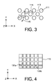
- the figure 3 represents a schematic top view of a porous getter material. We see on this figure 3 spaces 113 between columnar grains 111 of getter material allow circulation of the gases within the getter material, this circulation being represented by arrows 115.
- "Materials Science of Thin Films," Second Edition, Milton Ohring, Academic Press, Chapter 9.2.1.2 SZM for Evaporated Films, page 498 discloses details of making such a porous material.
- the gas permeability of the portion of getter material 110 can also be obtained by structuring the portion of getter material 110 to form through it channels, or micro-channels, allowing gases to flow through the getter material .
- These channels obtained for example by the implementation of photolithography and etching steps, can pass through the portion of getter material 110 over its entire thickness (this thickness being for example between about 1 micron and 10 microns), from a front face of the portion of getter material 110 located on the side of the localized opening 116 until a rear face of the portion of getter material 110 on the side of the substrate 108.
- the channels are made through the portion of getter material 110 before it is covered by the hermetic protective layer 112.
- the figure 4 represents a schematic top view of the portion of getter material 110 comprising such channels 120.
- the permeability function is obtained by means of channels 120, for example arranged in the form of a grid composed of channels vertical 120a and horizontal channels 120b, perpendicular to each other.
- a gas can enter, from the front face of the getter material portion 110, through the portions of the channels 120 located at the opening or openings 116 made through the hermetic protection layer 112 and spread throughout the portion of getter material 110 circulating, both vertically and laterally, through the channels 120.
- the width of the channels is for example between about 100 nm and 1 micron.
- the channels 120 are preferably made such that they have a shape ratio (height / width) greater than or equal to 2.
- the channels 120 open at the side faces of the portion of getter material 110.
- the pattern formed by the channels 120 may be different from that represented on the figure 4 , and may not form a grid. Thus, the channels 120 may form for example a star, or any other pattern.
- the opening or openings 116 may have any shape, for example cylindrical, and have a dimension (for example a diameter in the case of openings of cylindrical shapes), in the plane (X, Y), between about 1 and 10 microns.
- the getter material can be thermally activated during its hermetic encapsulation. This thermal activation makes it possible to regenerate the pumping capacity potential of the getter material.
- the pumping capacity of the getter is preferably regenerated before making a local opening in the hermetic protection layer. Thus, a getter material is obtained with all its active potential encapsulated hermetically.
- This encapsulation of protection by the layer 112 makes it possible on the one hand to maintain this potential of active pumping capacity until the setting up of the getter in the device and the realization of the local opening 116 in the hermetic protection layer 112, forming an access channel to the getter material.
- the encapsulation can also play a role of protection against possible attacks of the process that remains to be achieved until the final product: for example during a chemical cleaning incompatible with the getter material (for example with an HF solution), or during a heat treatment in a pumpable atmosphere with the getter, for example at a temperature of about 400 ° C. under an N 2 atmosphere.
- the getter material is hermetically encapsulated, it is possible to degas the cover at temperatures such that a non-hermetically protected getter would activate and perform a gaseous pumping (in the chamber of the degassing chamber or during the delivery in the air). Because the getter material is hermetically encapsulated, hood degassing and venting does not degrade the potential pumping capacity of the getter.
- the getter structure 104 may comprise the portion of gas permeable getter material 110 which is completely surrounded by the hermetic protective layer 112.
- a configuration is for example obtained by first producing a deposit of a first portion 112a of the hermetic protection layer 112, this first part 112a forming a portion of material (flat in the example described here) disposed against the substrate 108.
- the portion of gas-permeable getter material 110 is then deposited on the first part 112a of the hermetic protection layer 112. Channels are optionally made through the portion of gas-permeable getter material 110.
- the deposition of a second portion 112b of the hermetic protective layer 112 is carried out. such that this hermetic protective layer 112 completely surrounds and hermetically protects the portion of gas permeable getter material 110. All these steps will advantageously be performed in the same vacuum cycle or in the same atmosphere.
- the getter structure 104 and the microcomponent 102 are encapsulated within the cavity 106 formed by sealing the cover 114 to the substrate 108.
- One or more openings 116 are then made through the hermetic protective layer 112.
- Such a variant is advantageously achieved when the substrate 108 does not provide sufficient hermeticity to hermetically protect the portion of gas permeable getter material 110.
- a third embodiment is shown on the Figure 2B .
- the portion of gas permeable getter material 110 covers another portion of getter material 118.
- the hermetic protective layer 112 thus completely surrounds the portion of gas permeable getter material 110 as well as the other portion of getter material 118.
- the portion of getter material 118 for example a thickness between about 100 nm and 10 microns.
- the entire face, called the front face, of the other portion of getter material 118 lying against the portion of gas-permeable getter material 110 can achieve absorption and and / or gas adsorption through the porosities and / or the channels passing through the portion of gas permeable getter material 110, the localized opening or openings made through the protective layer 112 opening onto the portion of gas permeable getter material 110.
- the getter structure is for example obtained by producing, on the face of the substrate 108 on which the microcomponent 102 is disposed, the portions of the first portion 112a of the hermetic protection layer 112, which are then not not covered by the getter material 110.
- a deposit of the getter material intended to form the portion 118 is then produced and structured (for example an etching), in order to keep only the portion of getter material 118 whose dimensions correspond to the desired dimensions, here equivalent to those of the gas-permeable getter portion 110 to be produced.
- the portion of gas permeable getter material 110 is then made on the portion of getter material 118, the assembly then being encapsulated by the second portion 112b of the hermetic protective layer 112.
- the portion of getter material 118 can be made in one step by depositing the getter material through a stencil, thereby directly forming the portion of getter material 118 to the desired dimensions.
- the getter material portions 118 and 110 can be made both by two successive depositions through the same stencil, possibly during the same vacuum cycle, that is to say without air release between these two deposits.
- the second portion 112b of the hermetic protection layer 112 may also be made by a deposit implemented successively to the realization of the portion of getter material 110, during a single vacuum cycle.
- the portions of getter material 118 and 110 are inverted in the stack.
- the getter structure 104 (successively formed by the portion of gas permeable getter material 110, the getter material portion 118 and the hermetic protection layer 112) and the microcomponent 102 may be encapsulated within the cavity 106 formed by sealing the cover 114 to the substrate 108.
- One or more openings 116 are then made through the hermetic protective layer 112, for example by laser impact.
- the portion of getter material 110 permeable to gas is disposed under the portion of getter material 118 and thus provides access to the rear face of the portion 118.
- the portion 110 has dimensions greater than those of the portion 118 so that the opening 116 opens directly on this portion 110.
- the getter material of the portion 110 thus carries out a gas absorption and / or adsorption through the opening (s) 116, and the getter material of the other portion 118 carries a gas absorption and / or adsorption through the or the openings 116 and through the porosities and / or channels of the getter portion 110 permeable to gas.
- Such a configuration has the advantage that the entire surface of the getter material 118 (rear face in the case of the Figure 2C ) on the side of the gas-permeable getter material portion 110 can achieve gas absorption and / or adsorption, even if a single small opening 116 is made through the hermetic protective layer 112.
- a getter structure comprising at least two different getter materials that may have different absorption and / or gas adsorption properties.
- the portion of gas permeable getter material 110 may partially or completely surround the other portion of getter material 118, and may thus cover the lateral faces and / or the rear face (that located on the side of the substrate 108) of the portion of getter material 118.
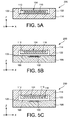
- the Figure 5A represents a device 200 according to a fourth embodiment comprising the getter structure 104 similar to that previously described in connection with the figure 1 .
- the getter structure 104 comprises the portion of gas permeable getter material 110 covered by the hermetic protection layer 112.
- the getter structure 104 is formed on the cover 114 which serves as a support for the portion of gas permeable getter material 110 and the protective layer 112.
- the cover 114 has lateral portions 122 intended to form side walls of the cavity 106 in which the getter structure 104 will be encapsulated with the microcomponent 102.
- the cover 114 is then assembled to the substrate 108 on which the microcomponent 102 is made, for example of the MEMS and / or NEMS type, thus forming the device 200 (FIG. Figure 5B ).
- the microcomponent 102 is thus encapsulated in the cavity 106 formed between the cover 114 and the substrate 108 and in which the getter structure 104 is also encapsulated.
- the side walls of the cavity 106 correspond to the lateral portions 122 of the cover 114.
- the assembly lateral portions 122 to the substrate 108 is formed by a seal hermetically sealing the cavity 106, obtained for example by molecular bonding or any other suitable sealing technique such as anodic or eutectic sealing.
- the different technological steps subsequently performed on the device 200 therefore have no impact on the gas-permeable getter material 110 as long as it is protected by the hermetic protection layer 112.
- the pumping capacities of the gas permeable getter material 110 are preserved as long as it is hermetically confined between the protective layer 112 and the cover 114.
- the opening 116 is made through the hermetic protection layer 112 in order to form an access to the portion of gas-permeable getter material 110 ( Figure 5C ).
- This opening 116 is for example made by laser impact through the substrate 108 (for example based on a laser-transparent material used).
- this laser impact causes slag (solid waste)
- slag solid waste
- the gas-permeable getter material 110 can fulfill its function of absorption and / or gas adsorption through the opening 116. It is thus possible to produce, for example, an environment under reduced pressure in the cavity 106. around the microcomponent 102.
- the getter structure 104 may correspond to one of those previously described in connection with the Figures 2A and 2B , that is to say, may comprise another portion of getter material 118 and / or be completely surrounded by the hermetic protective layer 112.
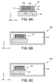
- the Figures 6A to 6C represent the steps of producing a device 300 according to a fifth embodiment.
- the getter structure 104 here comprises a stack of several portions of getter material (two on the example of the figure 6 ) 118a and 118b disposed on a portion of the substrate 108.
- the portions of getter material 118a, 118b are here entirely surrounded by portions of gas permeable getter material 110a, 110b.
- the assembly of this stack is protected by the hermetic protection layer 112 which completely surrounds the portions of gas-permeable getter material 110a, 110b, and thus completely covers the other portions of getter material 118a, 118b.
- all the faces of the other portions of getter material 118a, 118b are in contact with the gas-permeable getter material of the portions 110a, 110b.
- a getter structure 104 can be used autonomously, and can for example be arranged in a cavity 150 of a device 300, for example a screen tube (see FIG. Figure 6B ).
- the gas permeability of the getter material portions 110a, 110b is obtained by means of channels formed through the portions 110a, 110b and / or by virtue of the fact that the getter material of the portions 110a, 110b is porous.
- a local aperture of the getter structure 104 is created in order to expose a portion of the getter material portions. permeable to gases 110a, 110b ( Figure 6C ).
- This opening is for example obtained by breaking, for example by a shock of the getter structure 104 against a wall of the cavity 150 or by a laser shot, a portion of the getter structure 104.
- It is possible to facilitate the realization of the local opening 124 of the getter structure 104 by first performing a mechanical primer within the getter structure 104. This opening 124 can be achieved by keeping intact the portions of getter material 118a, 118b .
- the gas permeable getter material portions 110a, 110b and the other portions getter material 118a, 118b can achieve absorption and / or gas adsorption from all their faces (front, back and side faces).
- the getter structure 104 represented on the Figure 6A can be obtained by first making a first portion 112a of the hermetic protective layer 112, for example by deposition, this portion forming a flat layer portion disposed against the substrate 108.
- a first portion (also in the form of a planar portion) of the first portion of gas-permeable getter material 110a is then formed on the first portion 112a of the airtight protective layer 112.
- the first other portion of material getter 118a is then deposited on the first portion of the first portion of gas permeable getter material 110a.
- a second portion of the first portion of gas permeable getter material 110a is then deposited on the first other portion of getter material 118a such that the first other portion of getter material 118a is completely surrounded by the first portion of gas permeable getter material 110a.
- the second other portion of getter material 118b is then deposited on the first portion of gas permeable getter material 110a, for example using the same stencil used for depositing the first other portion of getter material 118a.
- the second portion of gas permeable getter material 110b is then deposited by completely covering the second other portion of getter material 118b.
- the getter material is generally made active after it has been deposited (when the different deposits have not been performed during the same vacuum cycle) and for example after its encapsulation in the hermetic protection layer 112, by a thermal activation step.
- such a thermal activation can be carried out at a temperature for example of between about 350 ° C. and 450 ° C.
- the getter material portion or portions are planar because the various supports on which the getter material portion (s) are made have a substantially flat surface.
- the portion of getter material is not flat but has reliefs (hollows and / or bumps or protrusions).
- the portions of gas-permeable getter material may be arranged next to each other and / or one above the other, and possibly spaced apart from each other.
Landscapes
- Engineering & Computer Science (AREA)
- Microelectronics & Electronic Packaging (AREA)
- Computer Hardware Design (AREA)
- Solid-Sorbent Or Filter-Aiding Compositions (AREA)
- Micromachines (AREA)
Abstract
- réalisation d'une structure getter (104) comportant au moins une portion de matériau getter perméable aux gaz (110) recouverte par au moins une couche de protection (112) hermétique aux gaz ;
- encapsulation hermétique de la structure getter dans une cavité (106) ;
- réalisation d'au moins une ouverture localisée (116) traversant la couche de protection et formant un accès à la portion de matériau getter perméable aux gaz.
Description
- L'invention concerne le domaine des structures getter, c'est-à-dire des structures comprenant un ou plusieurs matériaux getter pour réaliser une absorption et/ou une adsorption gazeuse dans un environnement clos. Une telle structure peut notamment être utilisée dans le domaine des microcomposants tels que les microsystèmes électromécaniques (MEMS) ou nanosystèmes électromécaniques (NEMS), par exemple des accéléromètres, des gyromètres, ou tout autre dispositif par exemple destiné à être encapsulé dans un environnement sous vide poussé, sous pression contrôlée, ou encore sous atmosphère protectrice.
- Un matériau getter est un matériau comportant, de façon intrinsèque et/ou de par sa morphologie microscopique, des propriétés d'absorption et/ou d'adsorption gazeuse. Un tel matériau getter peut ainsi former une pompe de gaz chimique lorsque celui-ci est disposé dans un environnement clos. Ce type de matériau peut également être utilisé dans de nombreuses applications microélectroniques telles que les tubes à vide, les systèmes à effet de champ ou encore avec des microcomposants tels que les MEMS ou NEMS pour réaliser par exemple un environnement sous vide poussé ou sous pression contrôlée. Dans le cas des MEMS ou NEMS encapsulés, un environnement sous vide poussé formé autour du dispositif permet par exemple d'obtenir un meilleur fonctionnement des systèmes mécaniques résonnants mais aussi des systèmes optiques sensibles à l'absorption du rayonnement lumineux par des gaz environnants du dispositif.
- Des matériaux getter non évaporables (appelés NEG) sont par exemple des métaux tels que du titane, du zirconium, de l'hafnium, ou encore des alliages métalliques binaires de ces trois métaux. Un tel matériau getter non évaporable est généralement déposé directement sur une paroi de l'enceinte dans laquelle on cherche à réaliser une pompe chimique sous la forme d'une couche mince. Ce matériau est ensuite activé thermiquement en le chauffant à travers la paroi de l'enceinte sur laquelle il est déposé.
- Le document
US 6 923 625 B2 décrit la réalisation d'une telle couche mince de matériau getter. Après avoir formé le matériau getter, celui-ci est protégé par une fine couche de protection, par exemple composée de métal, permettant d'empêcher une contamination ou une oxydation du matériau getter, et également d'empêcher que le matériau getter réalise une absorption gazeuse avant qu'il soit encapsulé. La couche de protection est ensuite supprimée afin d'exposer le matériau getter aux gaz environnants. - Le document
FR 2 883 099 - Dans ces deux documents, la couche de protection du matériau getter est supprimée grâce à un traitement thermique entraînant la diffusion ou le fluage de la couche de protection, exposant ainsi le matériau getter dans la cavité. Or, ce traitement thermique peut être gênant voir incompatible avec le reste de la structure encapsulée compte tenu des budgets thermiques mis en jeu.
- Un but de la présente invention est de proposer une nouvelle structure getter pouvant être utilisée pour réaliser une absorption et/ou une adsorption gazeuse par exemple dans une cavité fermée hermétiquement, dans laquelle le matériau getter est protégé hermétiquement lors de sa réalisation, et ne nécessitant pas la mise en oeuvre d'un traitement thermique pour exposer le matériau getter aux gaz environnants.
- Il est ainsi proposé une structure getter comportant au moins une portion de matériau getter perméable aux gaz recouverte par au moins une couche de protection hermétique aux gaz, et dans laquelle au moins une ouverture localisée traverse la couche de protection et forme un accès à la portion de matériau getter perméable aux gaz.
- La présente invention propose un procédé de réalisation d'un dispositif comportant au moins les étapes de :
- réalisation d'une structure getter comportant au moins une portion de matériau getter perméable aux gaz recouverte par au moins une couche de protection hermétique aux gaz ;
- encapsulation hermétique de la structure getter dans une cavité ;
- réalisation d'au moins une ouverture localisée traversant la couche de protection et formant un accès à la portion de matériau getter perméable aux gaz.
- Ainsi, en réalisant une ouverture localisée à travers la couche de protection, c'est-à-dire une ouverture réalisée à travers une partie seulement de la couche de protection hermétique et telle qu'une ou plusieurs portions restantes de la couche de protection hermétique recouvre la portion de matériau getter perméable aux gaz, il n'est pas nécessaire de supprimer totalement la couche de protection hermétique aux gaz lorsque l'on réalise une encapsulation de la structure getter. De plus, une telle ouverture localisée est réalisée sans mettre en oeuvre un traitement thermique pouvant endommager le reste de la structure.
- On entend par « perméabilité » d'une portion de matériau son aptitude à permettre la circulation de gaz dans ladite portion de matériau, aussi bien dans au moins une direction parallèle à un plan principal de la portion que dans une direction perpendiculaire à ce plan. La portion de matériau getter est ici perméable aux gaz, c'est-à-dire que des gaz peuvent circuler à travers cette portion, aussi bien latéralement que verticalement.
- La portion de matériau getter perméable aux gaz peut être disposée contre un support, des portions de la couche de protection pouvant reposer sur le support. Dans ce cas, la portion de matériau getter perméable aux gaz est encapsulée entre le support et la couche de protection.
- Une première partie de la couche de protection peut être disposée contre un support, la portion de matériau getter perméable aux gaz pouvant être disposée au-dessus de, ou sur, cette première partie de la couche de protection, une seconde partie de la couche de protection pouvant recouvrir la portion de matériau getter perméable aux gaz et reposer sur la première partie de la couche de protection. Dans ce cas, la portion de matériau getter perméable aux gaz est entièrement encapsulée par la couche de protection.
- L'ensemble formé par la portion de matériau getter perméable aux gaz et la couche de protection qui encapsule le matériau getter peut être formé directement sur le support ou bien être rapporté sur celui-ci après avoir été réalisé.
- La portion de matériau getter perméable aux gaz peut être disposée contre au moins une autre portion de matériau getter distincte de la portion de matériau getter perméable aux gaz telle que ladite autre portion de matériau getter soit apte à réaliser une absorption et/ou une adsorption gazeuse à travers au moins la portion de matériau getter perméable aux gaz.
- La portion de matériau getter perméable aux gaz peut entourer tout ou partie de ladite autre portion de matériau getter.
- La portion de matériau getter perméable aux gaz peut comporter un ou plusieurs canaux réalisés dans, ou à travers, ladite portion de matériau getter perméable aux gaz. Dans ce cas, des gaz peuvent circuler dans tout ou partie de la portion de matériau getter à travers ces canaux.
- La portion de matériau getter perméable aux gaz peut être composée d'au moins un matériau poreux. Dans ce cas, le matériau getter comporte des porosités, ou pores, latérales et verticales permettant aux gaz de circuler dans toute la portion de matériau getter à travers ces porosités.
- Les porosités du matériau getter poreux sont par exemple ouvertes et de dimensions comprises entre environ quelques nanomètres et quelques centaines de nanomètres, par exemple comprises entre environ 2 nm et 900 nm. Les dimensions des porosités du matériau getter poreux peuvent influer sur la vitesse de l'accessibilité des gaz au matériau getter.
- La couche de protection peut avoir une épaisseur supérieure à environ 100 nm.
- La structure getter peut comporter un empilement de plusieurs portions de matériau getter perméables aux gaz et de plusieurs autres portions de matériau getter, au moins une face de chacune desdites autres portions de matériau getter pouvant être disposée contre au moins une des portions de matériau getter perméables aux gaz telle que chacune desdites autres portions de matériau getter soit apte à réaliser une absorption et/ou une adsorption gazeuse par ladite face à travers ladite au moins une des portions de matériau getter perméables aux gaz, la couche de protection pouvant recouvrir ledit empilement.
- La couche de protection peut encapsuler entièrement la ou les portions de matériau getter perméables aux gaz et, lorsque la structure getter comporte au moins une autre portion de matériau getter, la couche de protection peut encapsuler entièrement ladite ou lesdites autres portions de matériau getter, l'ouverture localisée pouvant former un accès au moins à la ou aux portions de matériau getter perméables aux gaz. Lorsque la structure getter comporte ladite ou lesdites autres portions de matériau getter, l'ouverture localisée peut former en outre un accès à ladite ou auxdites autres portions de matériau getter, éventuellement à travers les portions de matériau getter perméables.
- L'invention concerne également un dispositif comportant au moins une cavité dans laquelle est encapsulée hermétiquement au moins une structure getter telle que décrite ci-dessus. Dans un tel dispositif, l'ouverture localisée est réalisée avantageusement après l'encapsulation de la structure getter dans la cavité.
- La cavité peut être formée entre un substrat et un capot, la structure getter pouvant être solidaire du substrat et/ou du capot.
- Le dispositif peut comporter en outre au moins un microcomposant encapsulé hermétiquement dans la cavité.
- Il est également décrit un procédé de réalisation d'une structure getter, comportant au moins les étapes de :
- réalisation d'au moins une portion de matériau getter perméable aux gaz ;
- réalisation d'au moins une couche de protection hermétique aux gaz recouvrant la portion de matériau getter perméable aux gaz ;
- réalisation d'au moins une ouverture localisée à travers la couche de protection hermétique, formant un accès à la portion de matériau getter perméable aux gaz.
- L'ouverture localisée peut être réalisée par au moins une fusion localisée de la couche de protection (par exemple un impact laser localisé sur la couche de protection ou une fusion eutectique de la couche de protection avec un matériau fusible reporté localement sur cette couche à l'endroit où l'ouverture doit être réalisée) et/ou en cassant une partie de la structure getter.
- La portion de matériau getter perméable aux gaz peut être réalisée par au moins un dépôt de matériau getter sur un support, la couche de protection pouvant être déposée sur la portion de matériau getter perméable aux gaz et sur une partie du support.
- Le procédé peut comporter en outre, avant la réalisation de la portion de matériau getter perméable aux gaz, la réalisation d'une première partie de la couche de protection contre un support, la portion de matériau getter perméable aux gaz pouvant être réalisée ensuite sur cette première partie de la couche de protection, et peut comporter en outre la réalisation d'une seconde partie de la couche de protection recouvrant la portion de matériau getter perméable aux gaz et reposant sur la première partie de la couche de protection.
- Le procédé peut comporter en outre, entre l'étape de réalisation de la portion de matériau getter perméable aux gaz et l'étape de réalisation de la couche de protection, une étape de réalisation d'au moins une autre portion de matériau getter distincte de la portion de matériau getter perméable aux gaz et disposée contre la portion de matériau getter perméable aux gaz telle que ladite autre portion de matériau getter soit apte à réaliser une absorption et/ou une adsorption gazeuse à travers au moins la portion de matériau getter perméable aux gaz, la couche de protection pouvant recouvrir ladite autre portion de matériau getter.
- Le procédé peut comporter en outre, avant l'étape de réalisation de la portion de matériau getter perméable aux gaz, une étape de réalisation d'au moins une autre portion de matériau getter distincte de la portion de matériau getter perméable aux gaz, la portion de matériau getter perméable aux gaz pouvant être réalisée sur ladite autre portion de matériau getter telle que ladite autre portion de matériau getter soit apte à réaliser une absorption et/ou une adsorption gazeuse à travers au moins la portion de matériau getter perméable aux gaz, la couche de protection pouvant recouvrir ladite portion de matériau getter perméable aux gaz.
- La portion de matériau perméable aux gaz peut être réalisée telle qu'elle entoure, ou déborde de, tout ou partie de ladite autre portion de matériau getter.
- Le procédé peut comporter la réalisation d'un empilement de plusieurs portions de matériau getter perméables aux gaz et de plusieurs autres portions de matériau getter tel qu'au moins une face de chacune desdites autres portions de matériau getter soit disposée contre au moins une des portions de matériau getter perméables aux gaz, chacune desdites autres portions de matériau getter pouvant être apte à réaliser une absorption et/ou une adsorption gazeuse par ladite face à travers ladite au moins une des portions de matériau getter perméables aux gaz, la couche de protection pouvant recouvrir ledit empilement.
- La couche de protection peut encapsuler entièrement la ou les portions de matériau getter perméables aux gaz et, lorsque la structure getter comporte au moins une autre portion de matériau getter, la couche de protection peut encapsuler entièrement ladite ou lesdites autres portions de matériau getter, l'ouverture localisée pouvant former un accès au moins à la ou aux portions de matériau getter perméables aux gaz. Lorsque la structure getter comporte ladite ou lesdites autres portions de matériau getter, l'ouverture localisée peut former en outre un accès à ladite ou auxdites portions de matériau getter.
- L'invention concerne également un procédé de réalisation d'un dispositif comportant au moins les étapes de :
- réalisation d'une structure getter telle que décrite ci-dessus ;
- encapsulation hermétique de la structure getter dans une cavité ;
dans lequel l'ouverture localisée de la structure getter est réalisée après l'encapsulation hermétique de la structure getter dans la cavité. - La cavité peut être formée en solidarisant un substrat à un capot, la structure getter pouvant être solidaire du substrat et/ou du capot.
- Le procédé peut comporter en outre la réalisation d'un microcomposant et l'encapsulation hermétique du microcomposant dans la cavité.
- La présente invention sera mieux comprise à la lecture de la description d'exemples de réalisation donnés à titre purement indicatif et nullement limitatif en faisant référence aux dessins annexés sur lesquels :
- les
figures 1A et 1B représentent les étapes d'un procédé de réalisation d'un dispositif, objet de la présente invention, dans lequel un procédé de réalisation d'une structure getter est mis en oeuvre selon un premier mode de réalisation ; - les
figures 2A à 2C représentent des structures getter, objets de la présente invention, selon d'autres modes de réalisation ; - la
figure 3 représente une vue de dessus schématique d'un matériau getter poreux d'une structure getter, objet de la présente invention ; - la
figure 4 représente une vue de dessus schématique d'un matériau getter comportant des canaux ; - les
figures 5A à 5C représentent les étapes d'un procédé de réalisation d'un dispositif dans lequel un procédé de réalisation d'une structure getter, objet de la présente invention, est mis en oeuvre selon un quatrième mode de réalisation ; - les
figures 6A à 6C représentent les étapes d'un procédé de réalisation d'un dispositif dans lequel un procédé de réalisation d'une structure getter, objet de la présente invention, est mis en oeuvre selon un cinquième mode de réalisation. - Des parties identiques, similaires ou équivalentes des différentes figures décrites ci-après portent les mêmes références numériques de façon à faciliter le passage d'une figure à l'autre.
- Les différentes parties représentées sur les figures ne le sont pas nécessairement selon une échelle uniforme, pour rendre les figures plus lisibles.
- Les différentes possibilités (variantes et modes de réalisation) doivent être comprises comme n'étant pas exclusives les unes des autres et peuvent se combiner entre elles.
- On se réfère aux
figures 1A et 1B qui représentent les étapes de réalisation d'un dispositif 100 selon un premier mode de réalisation, comportant un microcomposant 102 destiné à être encapsulé, avec une structure getter 104, dans une cavité 106. - Le dispositif 100 comporte le microcomposant 102 réalisé sur un support, ici un substrat 108, par exemple formé d'une couche de matériau semi-conducteur. La structure getter 104 est également réalisée sur le substrat 108, à côté du microcomposant 102. Sur la
figure 1A , la structure getter 104 comporte une portion de matériau getter perméable aux gaz 110 formée sur le substrat 108 et une couche de protection 112, hermétique aux gaz et recouvrant complètement la portion de matériau getter perméable aux gaz 110. La portion de matériau getter perméable aux gaz 110 et la couche de protection hermétique 112 sont par exemple formées par des dépôts successifs avantageusement réalisés dans un même cycle de vide ou sous une même atmosphère. On entend par « même cycle de vide » le fait que l'on ne remet pas la structure à l'air libre. On peut éventuellement, dans un même cycle de vide, remettre la structure sous atmosphère neutre notamment pour le transfert d'un équipement à un autre, par exemple d'une chambre de dépôt à une autre, afin d'éviter de saturer le matériau getter déposé. - Le matériau getter de la portion 110 est un matériau getter non évaporable, par exemple du titane et/ou du zirconium et/ou du chrome et/ou du vanadium et/ou du niobium et/ou du tantale et/ou tout autre alliage ou matériau présentant des propriétés d'absorption et/ou adsorption gazeuse. La portion de matériau getter perméable aux gaz 110 a une épaisseur par exemple comprise entre environ 50 nm et 10 µm. La portion de matériau getter perméable aux gaz 110 pourra également être réalisée sous la forme d'une couche mince.
- La couche de protection hermétique 112 est par exemple composée d'or et/ou d'aluminium, et a par exemple une épaisseur comprise entre environ 100 nm et plusieurs micromètres ou plusieurs dizaines de micromètres, la limite supérieure de cette épaisseur étant liée uniquement à l'encombrement maximal souhaité au sein du dispositif 100. La couche de protection hermétique 112 protège ainsi la portion de matériau getter perméable aux gaz 110 lors de la mise en oeuvre d'étapes pouvant par exemple détériorer le matériau getter et/ou altérer les propriétés d'absorption et/ou d'adsorption gazeuse du matériau getter, par exemple dans le cas d'un nettoyage chimique par solution HF. Cette couche de protection 112 permet également d'empêcher temporairement le matériau getter 110 de réaliser un pompage gazeux (du fait que le matériau getter 110 est destiné à réaliser ce pompage gazeux qu'après avoir été disposé dans la cavité qui sera fermée hermétiquement). Dans ce premier mode de réalisation, la protection hermétique du matériau getter perméable aux gaz 110 est également assurée en partie par le substrat 108 contre lequel la portion de matériau getter perméable aux gaz 110 est disposée.
- Le matériau getter peut être tout d'abord déposé sous la forme d'une couche, par exemple par évaporation ou par pulvérisation, sur le substrat 108, puis structuré (par exemple par gravure) afin de former la portion 110 aux dimensions souhaitées, ou bien être réalisé directement par un dépôt du matériau getter à travers un pochoir.
- Comme représenté sur la
figure 1B , on réalise ensuite un scellement hermétique d'un capot 114 sur le substrat 108 afin d'encapsuler la structure getter 104 et le microcomposant 102 dans la même cavité 106. Le capot 114 est par exemple composé de verre. - Ainsi, le matériau getter de la structure 104 est protégé hermétiquement lors du scellement hermétique du capot 114 sur le substrat 108 par la couche de protection 112. La température à laquelle est réalisé ce scellement hermétique du capot 114 peut entrainer l'activation thermique de la portion de matériau getter perméable aux gaz 110. La couche de protection hermétique 112 permet donc d'éviter au matériau getter de réaliser une absorption et/ou une adsorption gazeuse lors de ce scellement.
- Lorsque l'on souhaite « activer » la fonction d'absorption et/ou d'adsorption gazeuse du matériau getter 110, après que le capot 114 soit scellé au substrat 108, on réalise alors une ouverture localisée 116 à travers la couche de protection hermétique 112, par exemple par impact laser à travers le capot 114. Le capot 114 est ici transparent (par exemple composé de verre) vis-à-vis du laser utilisé pour exposer localement le matériau getter 110 à travers l'ouverture 116, ce qui permet au laser de traverser le capot 114 et réaliser l'ouverture locale 116 par impact du laser sur le matériau de la couche de protection hermétique 112. L'ouverture 116 débouche sur la surface de la portion de matériau getter perméable aux gaz 110. La couche de protection hermétique 112 n'est donc pas complètement éliminée lorsque le matériau getter rempli sa fonction de pompage gazeux en étant exposé à l'atmosphère ambiante.
- Bien que l'ouverture 116 soit localisée, c'est-à-dire ne révélant qu'une partie de la portion de matériau getter perméable aux gaz 110, l'absorption et/ou l'adsorption gazeuse est réalisée par l'ensemble de la portion de matériau getter 110 grâce à la perméabilité aux gaz présentée par la portion 110.
- La perméabilité aux gaz de la portion de matériau getter 110 peut être obtenue du fait que le matériau getter de la portion 110 comporte des porosités ouvertes afin que du gaz puisse circuler à travers celles-ci. Dans ce cas, la portion de matériau getter 110 présente, en son sein, des porosités latérales (porosités présentant des ouvertures au niveau de ses faces latérales) et verticales (présentant des ouvertures au niveau de ses faces avant et arrière), ces différentes porosités communiquant entre elles au sein de la portion 110. Ainsi, du gaz peut circuler à travers les porosités de la portion 110.
- Un tel matériau getter poreux comporte des porosités verticales et latérales formées entre les grains du matériau getter, permettant la circulation d'un gaz au sein de la portion 110. Il est donc possible de réaliser une ouverture 116 de dimensions réduites. Un tel matériau getter poreux peut être obtenu par un dépôt réalisé à une température de dépôt Ts telle que le rapport Ts/Tm soit inférieur à environ 0,3, Tm étant la température de fusion du matériau getter, les températures Ts et Tm étant exprimées en Kelvin. Lorsque le matériau getter poreux est déposé par évaporation dans ces conditions de dépôt, le matériau getter poreux obtenu présente alors une structure colonnaire comprenant des cônes inversés (partie la plus large du cône en haut), en forme de dômes dans la partie supérieure, ces cônes étant séparés par des espaces vides. La
figure 3 représente une vue de dessus schématique d'un matériau getter poreux. On voit sur cettefigure 3 que des espaces 113 entre des grains colonnaires 111 de matériau getter permettent une circulation des gaz au sein du matériau getter, cette circulation étant représentée par des flèches 115. L'ouvrage « Materials Science of Thin Films », Second Edition, Milton Ohring, Academic Press, chapitre 9.2.1.2 SZM for Evaporated Films, page 498, décrit des détails de réalisation d'un tel matériau poreux. - La perméabilité aux gaz de la portion de matériau getter 110 peut également être obtenue en structurant la portion de matériau getter 110 afin de former à travers celle-ci des canaux, ou micro-canaux, permettant à des gaz de circuler à travers le matériau getter. Ces canaux, obtenus par exemple par la mise en oeuvre d'étapes de photolithographie et de gravure, peuvent traverser la portion de matériau getter 110 sur toute son épaisseur (cette épaisseur étant par exemple comprise entre environ 1 µm et 10 µm), depuis une face avant de la portion de matériau getter 110 se trouvant du côté de l'ouverture localisée 116 jusqu'à une face arrière de la portion de matériau getter 110 se trouvant du côté du substrat 108. Les canaux sont réalisés à travers la portion de matériau getter 110 avant que celle-ci ne soit recouverte par la couche de protection hermétique 112.
- La
figure 4 représente une vue de dessus schématique de la portion de matériau getter 110 comportant de tels canaux 120. On voit sur cette figure que la fonction de perméabilité est obtenue grâce à des canaux 120, par exemple disposés sous la forme d'un quadrillage composé de canaux verticaux 120a et de canaux horizontaux 120b, perpendiculaires les uns par rapport aux autres. Ainsi, un gaz peut entrer, depuis la face avant de la portion de matériau getter 110, par les parties des canaux 120 se trouvant au niveau de la ou des ouvertures 116 réalisées à travers la couche de protection hermétique 112 et se diffuser dans toute la portion de matériau getter 110 en circulant, aussi bien verticalement que latéralement, à travers les canaux 120. La largeur des canaux est par exemple comprise entre environ 100 nm et 1 µm. Les canaux 120 sont réalisés de préférence tels qu'ils présentent un rapport de forme (hauteur / largeur) supérieur ou égal à 2. Sur l'exemple de lafigure 4 , les canaux 120 débouchent au niveau des faces latérales de la portion de matériau getter 110. Toutefois, dans une variante, il est possible que les canaux 120 ne soient pas débouchant latéralement. - Le motif formé par les canaux 120 peut être différent de celui représenté sur la
figure 4 , et peut ne pas former un quadrillage. Ainsi, les canaux 120 peuvent former par exemple une étoile, ou n'importe quel autre motif. - Il est possible de réaliser plusieurs ouvertures locales 116 à travers la couche de protection hermétique 112, ces ouvertures formant différents accès au matériau getter 110. La ou les ouvertures 116 peuvent avoir une forme quelconque, par exemple cylindrique, et présenter une dimension (par exemple un diamètre dans le cas d'ouvertures de formes cylindriques), dans le plan (X,Y), comprise entre environ 1 et 10 µm.
- Si la portion de matériau getter 110 et la couche de protection hermétique 112 n'ont pas été réalisées dans le même cycle de vide, le matériau getter peut être activé thermiquement lors de son encapsulation hermétique. Cette activation thermique permet de régénérer le potentiel de capacité de pompage du matériau getter. On régénère de préférence le potentiel de capacité de pompage du getter avant de réaliser une ouverture locale dans la couche de protection hermétique. Ainsi, on obtient un matériau getter avec tout son potentiel actif encapsulé hermétiquement.
- Cette encapsulation de protection par la couche 112 permet d'une part de maintenir ce potentiel de capacité de pompage actif jusqu'à la mise en place du getter dans le dispositif et la réalisation de l'ouverture locale 116 dans la couche de protection hermétique 112, formant un canal d'accès au matériau getter. D'autre part, l'encapsulation peut aussi jouer un rôle de protection contre les éventuelles agressions du process qu'il reste à réaliser jusqu'au produit final : par exemple lors d'un nettoyage chimique incompatible avec le matériau getter (par exemple avec une solution HF), ou lors d'un traitement thermique sous atmosphère pompable par le getter, par exemple à une température d'environ 400°C sous atmosphère de N2.
- Le matériau getter étant encapsulé hermétiquement, il est possible de réaliser un dégazage du capot à des températures telles qu'un getter non hermétiquement protégé s'activerait et réaliserait un pompage gazeux (dans l'enceinte de la chambre de dégazage ou lors de la remise à l'air). Du fait que le matériau getter soit encapsulé hermétiquement, le dégazage du capot et la remise à l'air ne dégrade pas la capacité de pompage potentielle du getter.
- Dans un deuxième mode de réalisation représenté sur la
figure 2A , la structure getter 104 peut comporter la portion de matériau getter perméable aux gaz 110 qui est complètement entourée par la couche de protection hermétique 112. Une telle configuration est par exemple obtenue en réalisant tout d'abord un dépôt d'une première partie 112a de la couche de protection hermétique 112, cette première partie 112a formant une portion de matériau (plane dans l'exemple décrit ici) disposée contre le substrat 108. La portion de matériau getter perméable aux gaz 110 est ensuite déposée sur la première partie 112a de la couche de protection hermétique 112. Des canaux sont éventuellement réalisés à travers la portion de matériau getter perméable aux gaz 110. Enfin, on réalise le dépôt d'une seconde partie 112b de la couche de protection hermétique 112 telle que cette couche de protection hermétique 112 entoure complètement et protège hermétiquement la portion de matériau getter perméable aux gaz 110. Toutes ces étapes seront avantageusement réalisées dans un même cycle de vide ou sous une même atmosphère. - Bien que non représenté, et comme précédemment décrit en liaison avec la
figure 1B , la structure getter 104 et le microcomposant 102 sont encapsulés au sein de la cavité 106 formée par scellement du capot 114 au substrat 108. Une ou plusieurs ouvertures 116 sont ensuite réalisées à travers la couche de protection hermétique 112. Une telle variante est avantageusement réalisée lorsque le substrat 108 n'offre pas une herméticité suffisante pour protéger hermétiquement la portion de matériau getter perméable aux gaz 110. - Un troisième mode de réalisation est représenté sur la
figure 2B . Par rapport au deuxième mode de réalisation précédemment décrit en liaison avec lafigure 2A , la portion de matériau getter perméable aux gaz 110 recouvre une autre portion de matériau getter 118. La couche de protection hermétique 112 entoure donc complètement la portion de matériau getter perméable aux gaz 110 ainsi que l'autre portion de matériau getter 118. La portion de matériau getter 118 a par exemple une épaisseur comprise entre environ 100 nm et 10 µm. Compte tenu de la perméabilité de la portion de matériau getter 110, l'ensemble de la face, appelée face avant, de l'autre portion de matériau getter 118 se trouvant contre la portion de matériau getter perméable aux gaz 110 peut réaliser une absorption et/ou un adsorption gazeuse à travers les porosités et/ou les canaux traversant la portion de matériau getter perméable aux gaz 110, la ou les ouvertures localisées réalisées à travers la couche de protection 112 débouchant sur la portion de matériau getter perméable aux gaz 110. - Dans l'exemple décrit ici, la structure getter est par exemple obtenue en réalisant, sur la face du substrat 108 sur laquelle le microcomposant 102 est disposé, les portions de la première partie 112a de la couche de protection hermétique 112, qui ne sont alors pas recouvertes par le matériau getter 110. Sur cette première partie 112a, un dépôt du matériau getter destiné à former la portion 118 est ensuite réalisé et structuré (par exemple une gravure), afin de ne conserver que la portion de matériau getter 118 dont les dimensions correspondent aux dimensions souhaitées, ici équivalentes à celles de la portion de matériau getter perméable aux gaz 110 à réaliser. La portion de matériau getter perméable aux gaz 110 est ensuite réalisée sur la portion de matériau getter 118, l'ensemble étant ensuite encapsulé par la seconde partie 112b de la couche de protection hermétique 112.
- En variante, la portion de matériau getter 118 peut être réalisée en une seule étape en déposant le matériau getter à travers un pochoir, formant ainsi directement la portion de matériau getter 118 aux dimensions souhaitées. Dans un mode de réalisation avantageux, les portions de matériau getter 118 et 110 peuvent être réalisées toutes les deux par deux dépôts successifs à travers un même pochoir, éventuellement au cours d'un même cycle de vide, c'est-à-dire sans remise à l'air entre ces deux dépôts. La deuxième partie 112b de la couche de protection hermétique 112 pourra également être réalisée par un dépôt mis en oeuvre successivement à la réalisation de la portion de matériau getter 110, au cours d'un même cycle de vide.
- Selon une autre variante représentée sur la
figure 2C , les portions de matériau getter 118 et 110 sont inversées dans l'empilement. Comme précédemment décrit en liaison avec lafigure 1B , la structure getter 104 (formée successivement par la portion de matériau getter perméable aux gaz 110, la portion de matériau getter 118 et la couche de protection hermétique 112) et le microcomposant 102 peuvent être encapsulés au sein de la cavité 106 formée par scellement du capot 114 au substrat 108. Une ou plusieurs ouvertures 116 sont ensuite réalisées à travers la couche de protection hermétique 112, par exemple par impact laser. Dans ce mode de réalisation, la portion de matériau getter 110 perméable aux gaz est disposée sous la portion de matériau getter 118 et permet donc d'avoir accès à la face arrière de la portion 118. La portion 110 comporte des dimensions supérieures à celles de la portion 118 pour que l'ouverture 116 débouche directement sur cette portion 110. Le matériau getter de la portion 110 réalise donc une absorption et/ou une adsorption gazeuse à travers la ou les ouvertures 116, et le matériau getter de l'autre portion 118 réalise une absorption et/ou une adsorption gazeuse à travers la ou les ouvertures 116 et à travers les porosités et/ou les canaux de la portion getter 110 perméable aux gaz. Une telle configuration a pour avantage que toute la surface du matériau getter 118 (face arrière dans le cas de lafigure 2C ) se trouvant du côté de la portion de matériau getter perméable aux gaz 110 peut réaliser une absorption et/ou une adsorption gazeuse, même si une seule ouverture 116 de faibles dimensions est réalisée à travers la couche de protection hermétique 112. - Ainsi, on obtient une structure getter comprenant au moins deux matériaux getter différents pouvant présenter des propriétés d'absorption et/ou d'adsorption gazeuse différentes.
- En variante, il est possible que la portion de matériau getter perméable aux gaz 110 entoure en partie ou complètement l'autre portion de matériau getter 118, et peut donc recouvrir les faces latérales et/ou la face arrière (celle se trouvant du côté du substrat 108) de la portion de matériau getter 118.
- La
figure 5A représente un dispositif 200 selon un quatrième mode de réalisation comportant la structure getter 104 similaire à celle précédemment décrite en liaison avec lafigure 1 . La structure getter 104 comporte la portion de matériau getter perméable aux gaz 110 recouverte par la couche de protection hermétique 112. Dans ce quatrième mode de réalisation, la structure getter 104 est réalisée sur le capot 114 qui sert de support à la portion de matériau getter perméable aux gaz 110 et à la couche de protection 112. Le capot 114 comporte des portions latérales 122 destinées à former des parois latérales de la cavité 106 dans laquelle la structure getter 104 sera encapsulée avec le microcomposant 102. - Le capot 114 est ensuite assemblé au substrat 108 sur lequel est réalisé le microcomposant 102, par exemple de type MEMS et/ou NEMS, formant ainsi le dispositif 200 (
figure 5B ). Le microcomposant 102 se retrouve donc encapsulé dans la cavité 106 formée entre le capot 114 et le substrat 108 et dans laquelle est également encapsulée la structure getter 104. Les parois latérales de la cavité 106 correspondent aux portions latérales 122 du capot 114. L'assemblage des portions latérales 122 au substrat 108 est réalisé par un scellement fermant hermétiquement la cavité 106, obtenu par exemple par collage moléculaire ou toute autre technique de scellement adaptée telle qu'un scellement anodique ou eutectique. - Les différentes étapes technologiques réalisées ensuite sur le dispositif 200 n'ont donc pas d'impact sur le matériau getter perméable aux gaz 110 tant que celui-ci est protégé par la couche de protection hermétique 112.
- De plus, les capacités de pompage du matériau getter perméable aux gaz 110 sont préservées tant que celui-ci est confiné hermétiquement entre la couche de protection 112 et le capot 114.
- Lorsque l'on souhaite « activer » la fonction d'absorption / adsorption gazeuse du matériau getter, on réalise l'ouverture 116 à travers la couche de protection hermétique 112 afin de former un accès à la portion de matériau getter perméable aux gaz 110 (
figure 5C ). Cette ouverture 116 est par exemple réalisée par impact laser à travers le substrat 108 (par exemple à base d'un matériau transparent au laser utilisé). - Si cet impact laser provoque des scories (déchets solides), il est possible de réaliser cette ouverture 116 dans une portion de la couche de la protection 112 éloignée du microcomposant 102 afin de réduire ou supprimer la pollution de ces scories qui peuvent potentiellement altérer le fonctionnement du microcomposant 102.
- Grâce à cette ouverture 116, le matériau getter perméable aux gaz 110 peut remplir sa fonction d'absorption et/ou d'adsorption gazeuse à travers l'ouverture 116. On peut ainsi réaliser par exemple un environnement sous pression réduite dans la cavité 106, autour du microcomposant 102.
- Dans une variante de réalisation du dispositif 200, la structure getter 104 peut correspondre à l'une de celles précédemment décrites en liaison avec les
figures 2A et 2B , c'est-à-dire pouvant comporter une autre portion de matériau getter 118 et/ou être complètement entourée par la couche de protection hermétique 112. - Les
figures 6A à 6C représentent les étapes de réalisation d'un dispositif 300 selon un cinquième mode de réalisation. - Comme représenté sur la
figure 6A , la structure getter 104 comporte ici un empilement de plusieurs portions de matériau getter (deux sur l'exemple de lafigure 6 ) 118a et 118b disposées sur une partie du substrat 108. Les portions de matériau getter 118a, 118b sont ici entièrement entourées par des portions de matériau getter perméable aux gaz 110a, 110b. L'ensemble de cet empilement est protégé par la couche de protection hermétique 112 qui entoure complètement les portions de matériau getter perméable aux gaz 110a, 110b, et donc recouvre intégralement les autres portions de matériau getter 118a, 118b. Dans ce cinquième mode de réalisation, toutes les faces des autres portions de matériau getter 118a, 118b sont en contact avec le matériau getter perméable aux gaz des portions 110a, 110b. On obtient ainsi une structure getter 104 pouvant être utilisée de manière autonome, et pouvant par exemple être disposée dans une cavité 150 d'un dispositif 300, par exemple un tube écran (voirfigure 6B ). La perméabilité aux gaz des portions de matériau getter 110a, 110b est obtenue grâce à des canaux formés à travers les portions 110a, 110b et/ou grâce à au fait que le matériau getter des portions 110a, 110b est poreux. - Afin d'activer la fonction de pompage gazeux de la structure getter 104, on créé une ouverture locale de la structure getter 104 afin de mettre à nu une partie des portions de matériau getter perméable aux gaz 110a, 110b (
figure 6C ). Cette ouverture est par exemple obtenue en cassant, par exemple par un choc de la structure getter 104 contre une paroi de la cavité 150 ou par un tir laser, une partie de la structure getter 104. On obtient ainsi une ouverture locale 124 formée à travers la couche de protection hermétique 112 et formant un accès aux portions de matériau getter perméable aux gaz 110a, 110b et aux autres portions de matériau getter 118a, 118b via les porosités et/ou canaux des portions de matériau getter perméables aux gaz 110a, 110b. Il est possible de faciliter la réalisation de l'ouverture locale 124 de la structure getter 104 en réalisant au préalable une amorce mécanique au sein de la structure getter 104. Cette ouverture 124 peut être réalisée en conservant intacte les portions de matériau getter 118a, 118b. - Ainsi, par l'intermédiaire de l'ouverture 124 réalisée à travers la couche de protection 112 et qui débouche sur les portions de matériau getter perméables aux gaz 110a, 110b, les portions de matériau getter perméables aux gaz 110a, 110b et les autres portions de matériau getter 118a, 118b peuvent réaliser une absorption et/ou une adsorption gazeuse depuis l'ensemble de leurs faces (faces avant, arrière et latérales) .
- La structure getter 104 représentée sur la
figure 6A peut être obtenue en réalisant tout d'abord une première partie 112a de la couche de protection hermétique 112, par exemple par dépôt, cette partie formant une portion de couche plane disposée contre le substrat 108. Une première partie (également sous la forme d'une portion plane) de la première portion de matériau getter perméable aux gaz 110a est ensuite formée sur la première partie 112a de la couche de protection hermétique 112. La première autre portion de matériau getter 118a est ensuite déposée sur la première partie de la première portion de matériau getter perméable aux gaz 110a. Une seconde partie de la première portion de matériau getter perméable aux gaz 110a est ensuite déposée sur la première autre portion de matériau getter 118a telle que la première autre portion de matériau getter 118a soit complètement entourée par la première portion de matériau getter perméable aux gaz 110a. La deuxième autre portion de matériau getter 118b est ensuite déposée sur la première portion de matériau getter perméable aux gaz 110a, en utilisant par exemple le même pochoir que celui utilisé pour le dépôt de la première autre portion de matériau getter 118a. La deuxième portion de matériau getter perméable aux gaz 110b est ensuite déposée en recouvrant complètement la deuxième autre portion de matériau getter 118b. Enfin, on réalise le dépôt d'une seconde partie 112b de la couche de protection hermétique 112 telle que cette couche de protection hermétique 112 entoure et protège hermétiquement les portions de matériau getter 110a, 110b, 118a et 118b. Toutes ces étapes seront avantageusement réalisées dans un même cycle de vide. - Dans tous les modes de réalisation, le matériau getter est généralement rendu actif après son dépôt (lorsque les différents dépôts n'ont pas été réalisés au cours du même cycle de vide) et par exemple après son encapsulation dans la couche de protection hermétique 112, par une étape d'activation thermique.
- Par exemple, dans le cas d'un matériau getter composé de titane, une telle activation thermique peut être réalisée à une température par exemple comprise entre environ 350°C et 450°C.
- Dans tous les modes de réalisation précédemment décrits, la ou les portions de matériau getter sont planes du fait que les différents supports sur lesquels la ou les portions de matériau getter sont réalisées présentent une surface sensiblement plane.
- Toutefois, il est possible que la portion de matériau getter ne soit pas plane mais qu'elle présente des reliefs (creux et/ou bosses ou saillies).
- Dans tous les modes de réalisation précédemment décrits, il est possible que plusieurs portions de matériau getter perméables aux gaz soient entourées ou recouvertes par la couche de protection hermétique. Dans ce cas, les portions de matériau getter perméables aux gaz peuvent être disposées les unes à côté des autres et/ou les unes au-dessus des autres, et être éventuellement espacées les unes des autres.
Claims (15)
- Procédé de réalisation d'un dispositif (100, 200, 300) comportant au moins les étapes de :- réalisation d'une structure getter (104) comportant au moins une portion de matériau getter perméable aux gaz (110, 110a, 110b) recouverte par au moins une couche de protection (112, 112a, 112b) hermétique aux gaz ;- encapsulation hermétique de la structure getter (104) dans une cavité (106, 150) ;- réalisation d'au moins une ouverture localisée (116, 124) traversant la couche de protection (112, 112a, 112b) et formant un accès à la portion de matériau getter perméable aux gaz (110, 110a, 110b).
- Procédé selon la revendication 1, dans lequel la portion de matériau getter perméable aux gaz (110, 110a, 110b) comporte un ou plusieurs canaux (120a, 120b) réalisés dans ladite portion de matériau getter perméable aux gaz (110, 110a, 110b).
- Procédé selon l'une des revendications précédentes, dans lequel la portion de matériau getter perméable aux gaz (110, 110a, 110b) est composée d'au moins un matériau poreux.
- Procédé selon l'une des revendications précédentes, dans lequel la couche de protection (112, 112a, 112b) a une épaisseur supérieure à environ 100 nm.
- Procédé selon l'une des revendications précédentes, dans lequel la cavité (106) est formée entre un substrat (108) et un capot (114), la structure getter étant solidaire du substrat (108) et/ou du capot (114) .
- Procédé selon l'une des revendications précédentes, comportant en outre au moins un microcomposant (102) encapsulé hermétiquement dans la cavité (106).
- Procédé selon l'une des revendications précédentes, dans lequel l'ouverture localisée (116, 124) est réalisée par au moins une fusion localisée de la couche de protection (112, 112a, 112b) et/ou en cassant une partie de la structure getter (104).
- Procédé selon l'une des revendications précédentes, dans lequel la portion de matériau getter perméable aux gaz (110, 110a, 110b) est réalisée par au moins un dépôt de matériau getter sur un support (108, 114), la couche de protection (112, 112b) étant déposée sur la portion de matériau getter perméable aux gaz (110, 110a, 110b) et sur une partie du support (108, 114) .
- Procédé selon l'une des revendications 1 à 7, comportant en outre, avant la réalisation de la portion de matériau getter perméable aux gaz (110, 110a, 110b), la réalisation d'une première partie (112a) de la couche de protection (112) contre un support (108, 114), la portion de matériau getter perméable aux gaz (110, 110a, 110b) étant réalisée ensuite sur cette première partie (112a) de la couche de protection (112), et comportant en outre la réalisation d'une seconde partie (112b) de la couche de protection (112) recouvrant la portion de matériau getter perméable aux gaz (110, 110a, 110b) et reposant sur la première partie (112a) de la couche de protection (112).
- Procédé selon l'une des revendications précédentes, comportant en outre, entre une étape de réalisation de la portion de matériau getter perméable aux gaz (110, 110a, 110b) et une étape de réalisation de la couche de protection (112, 112a, 112b), une étape de réalisation d'au moins une autre portion de matériau getter (118, 118a, 118b) distincte de la portion de matériau getter perméable aux gaz (110, 110a, 110b) et disposée contre la portion de matériau getter perméable aux gaz (110, 110a, 110b) telle que ladite autre portion de matériau getter (118, 118a, 118b) soit apte à réaliser une absorption et/ou une adsorption gazeuse à travers au moins la portion de matériau getter perméable aux gaz (110, 110a, 110b), la couche de protection (112, 112a, 112b) recouvrant ladite autre portion de matériau getter (118, 118a, 118b).
- Procédé selon l'une des revendications 1 à 9, comportant en outre, avant une étape de réalisation de la portion de matériau getter perméable aux gaz (110, 110a, 110b), une étape de réalisation d'au moins une autre portion de matériau getter (118, 118a, 118b) distincte de la portion de matériau getter perméable aux gaz (110, 110a, 110b), la portion de matériau getter perméable aux gaz (110, 110a, 110b) étant réalisée sur ladite autre portion de matériau getter (118, 118a, 118b) telle que ladite autre portion de matériau getter (118, 118a, 118b) soit apte à réaliser une absorption et/ou une adsorption gazeuse à travers au moins la portion de matériau getter perméable aux gaz (110, 110a, 110b), la couche de protection (112, 112a, 112b) recouvrant ladite portion de matériau getter perméable aux gaz (110, 110a, 110b).
- Procédé selon la revendication 10, dans lequel la portion de matériau getter perméable aux gaz (110, 110a, 110b) est réalisée telle qu'elle entoure tout ou partie de ladite autre portion de matériau getter (118, 118a, 118b).
- Procédé selon l'une des revendications précédentes, comportant la réalisation d'un empilement de plusieurs portions de matériau getter perméables aux gaz (110a, 110b) et de plusieurs autres portions de matériau getter (118a, 118b) tel qu'au moins une face de chacune desdites autres portions de matériau getter (118a, 118b) soit disposée contre au moins une des portions de matériau getter perméables aux gaz (110a, 110b), chacune desdites autres portions de matériau getter (118a, 118b) étant apte à réaliser une absorption et/ou une adsorption gazeuse par ladite face à travers ladite au moins une des portions de matériau getter perméables aux gaz (110a, 110b), la couche de protection (112, 112a, 112b) recouvrant ledit empilement.
- Procédé selon l'une des revendications précédentes, dans laquelle la couche de protection (112, 112a, 112b) encapsule entièrement la ou les portions de matériau getter perméables aux gaz (110, 110a, 110b) et, lorsque la structure getter (104) comporte au moins une autre portion de matériau getter (118, 118a, 118b), la couche de protection (112, 112a, 112b) encapsule entièrement ladite ou lesdites autres portions de matériau getter (118, 118a, 118b), l'ouverture localisée (116, 124) formant un accès au moins à la ou aux portions de matériau getter perméables aux gaz (110, 110a, 110b).
- Procédé selon l'une des revendications précédentes, comportant en outre la réalisation d'un microcomposant (102) et l'encapsulation hermétique du microcomposant (102) dans la cavité (106).
Applications Claiming Priority (1)
| Application Number | Priority Date | Filing Date | Title |
|---|---|---|---|
| FR1155564A FR2976932A1 (fr) | 2011-06-23 | 2011-06-23 | Structure a materiau getter protege hermetiquement lors de sa realisation |
Publications (2)
| Publication Number | Publication Date |
|---|---|
| EP2537797A1 true EP2537797A1 (fr) | 2012-12-26 |
| EP2537797B1 EP2537797B1 (fr) | 2016-06-15 |
Family
ID=46245531
Family Applications (1)
| Application Number | Title | Priority Date | Filing Date |
|---|---|---|---|
| EP12172748.1A Not-in-force EP2537797B1 (fr) | 2011-06-23 | 2012-06-20 | Structure à matériau getter protégée hermétiquement lors de sa réalisation |
Country Status (3)
| Country | Link |
|---|---|
| US (1) | US20120328779A1 (fr) |
| EP (1) | EP2537797B1 (fr) |
| FR (1) | FR2976932A1 (fr) |
Cited By (2)
| Publication number | Priority date | Publication date | Assignee | Title |
|---|---|---|---|---|
| WO2014187505A1 (fr) * | 2013-05-24 | 2014-11-27 | Epcos Ag | Boîtier de dispositif à système micro-électromécanique et procédé de production du boîtier de dispositif à système micro-électromécanique |
| WO2020094292A1 (fr) * | 2018-11-08 | 2020-05-14 | Lynred | Boitier hermetique comportant un getter, composant optoelectronique ou dispositif mems integrant un tel boitier hermetique et procede de fabrication associe |
Families Citing this family (6)
| Publication number | Priority date | Publication date | Assignee | Title |
|---|---|---|---|---|
| FR3014241B1 (fr) | 2013-11-29 | 2017-05-05 | Commissariat Energie Atomique | Structure d'encapsulation comprenant des tranchees partiellement remplies de materiau getter |
| FR3021645B1 (fr) | 2014-06-03 | 2019-06-14 | Commissariat A L'energie Atomique Et Aux Energies Alternatives | Structure d'encapsulation a plusieurs cavites munies de canaux d'acces de hauteurs differentes |
| FR3026560B1 (fr) | 2014-09-30 | 2016-10-28 | Commissariat Energie Atomique | Structure d'encapsulation pourvue d'un capot et d'un substrat, pour connecter au moins un nano-objet sur une face du substrat et en reprendre le contact au travers du capot, et procede de fabrication de la structure |
| FR3027380A1 (fr) * | 2014-10-17 | 2016-04-22 | Commissariat Energie Atomique | Dispositif de refroidissement par liquide caloporteur pour composants electroniques |
| FR3030475B1 (fr) | 2014-12-17 | 2017-01-20 | Commissariat Energie Atomique | Structure getter multi-niveaux et structure d'encapsulation comportant une telle structure getter multi-niveaux |
| US9556019B2 (en) * | 2015-05-06 | 2017-01-31 | Invensense, Inc. | Cavity pressure modification using local heating with a laser |
Citations (4)
| Publication number | Priority date | Publication date | Assignee | Title |
|---|---|---|---|---|
| US6923625B2 (en) | 2002-01-07 | 2005-08-02 | Integrated Sensing Systems, Inc. | Method of forming a reactive material and article formed thereby |
| US20060137460A1 (en) * | 2002-09-26 | 2006-06-29 | Gerhard Lammel | Micromechanical component and method |
| FR2883099A1 (fr) | 2005-03-14 | 2006-09-15 | Commissariat Energie Atomique | Protection d'un getter en couche mince |
| WO2009041950A1 (fr) * | 2007-09-28 | 2009-04-02 | Qualcomm Mems Technologies, Inc. | Procédé de fabrication d'un boîtier de microsystème électromécanique (mems) en utilisant un déshydratant partiellement réactivé |
Family Cites Families (2)
| Publication number | Priority date | Publication date | Assignee | Title |
|---|---|---|---|---|
| ITMI20031178A1 (it) * | 2003-06-11 | 2004-12-12 | Getters Spa | Depositi multistrato getter non evaporabili ottenuti per |
| FR2922202B1 (fr) * | 2007-10-15 | 2009-11-20 | Commissariat Energie Atomique | Structure comportant une couche getter et une sous-couche d'ajustement et procede de fabrication. |
-
2011
- 2011-06-23 FR FR1155564A patent/FR2976932A1/fr not_active Withdrawn
-
2012
- 2012-06-20 EP EP12172748.1A patent/EP2537797B1/fr not_active Not-in-force
- 2012-06-22 US US13/530,513 patent/US20120328779A1/en not_active Abandoned
Patent Citations (4)
| Publication number | Priority date | Publication date | Assignee | Title |
|---|---|---|---|---|
| US6923625B2 (en) | 2002-01-07 | 2005-08-02 | Integrated Sensing Systems, Inc. | Method of forming a reactive material and article formed thereby |
| US20060137460A1 (en) * | 2002-09-26 | 2006-06-29 | Gerhard Lammel | Micromechanical component and method |
| FR2883099A1 (fr) | 2005-03-14 | 2006-09-15 | Commissariat Energie Atomique | Protection d'un getter en couche mince |
| WO2009041950A1 (fr) * | 2007-09-28 | 2009-04-02 | Qualcomm Mems Technologies, Inc. | Procédé de fabrication d'un boîtier de microsystème électromécanique (mems) en utilisant un déshydratant partiellement réactivé |
Non-Patent Citations (1)
| Title |
|---|
| CAPLET S ET AL: "Vacuum wafer-level packaging for MEMS applications", PROCEEDINGS OF SPIE, SPIE, US, vol. 4979, 27 January 2003 (2003-01-27), pages 271 - 278, XP002360340, ISSN: 0277-786X, DOI: 10.1117/12.478249 * |
Cited By (6)
| Publication number | Priority date | Publication date | Assignee | Title |
|---|---|---|---|---|
| WO2014187505A1 (fr) * | 2013-05-24 | 2014-11-27 | Epcos Ag | Boîtier de dispositif à système micro-électromécanique et procédé de production du boîtier de dispositif à système micro-électromécanique |
| US9479138B2 (en) | 2013-05-24 | 2016-10-25 | Epcos Ag | Microelectromechanical systems device package and method for producing the microelectromechanical systems device package |
| WO2020094292A1 (fr) * | 2018-11-08 | 2020-05-14 | Lynred | Boitier hermetique comportant un getter, composant optoelectronique ou dispositif mems integrant un tel boitier hermetique et procede de fabrication associe |
| FR3088319A1 (fr) * | 2018-11-08 | 2020-05-15 | Ulis | Boitier hermetique comportant un getter, composant optoelectronique ou dispositif mems integrant un tel boitier hermetique et procede de fabrication associe |
| CN112930318A (zh) * | 2018-11-08 | 2021-06-08 | 丽瑞德公司 | 包括吸气剂的气密壳体、并入这样的气密壳体的光电部件或mems装置、以及相关的制造方法 |
| US11305983B2 (en) | 2018-11-08 | 2022-04-19 | Lynred | Hermetic housing comprising a getter, optoelectronic component or MEMS device incorporating such a hermetic housing and associated production method |
Also Published As
| Publication number | Publication date |
|---|---|
| US20120328779A1 (en) | 2012-12-27 |
| FR2976932A1 (fr) | 2012-12-28 |
| EP2537797B1 (fr) | 2016-06-15 |
Similar Documents
| Publication | Publication Date | Title |
|---|---|---|
| EP2537797B1 (fr) | Structure à matériau getter protégée hermétiquement lors de sa réalisation | |
| EP2141117B1 (fr) | Procédé d'encapsulation d'un dispositif microélectronique par un materiau getter | |
| EP2308798B1 (fr) | Procédé de traitement d'un matériau getter et procédé d'encapsulation d'un tel matériau getter | |
| EP1878693B1 (fr) | Microcomposant encapsule equipe d'au moins un getter | |
| EP2451740B1 (fr) | Cavite etanche et procede de realisation d'une telle cavite etanche. | |
| EP2204347B1 (fr) | Structure comportant une couche getter et une sous-couche d'ajustement de la température d'activation et procédé de fabrication | |
| EP2450949B1 (fr) | Structure d'encapsulation d'un micro-dispositif comportant un matériau getter | |
| EP2692689B1 (fr) | Procédé d'encapsulation d'un dispositif microélectronique | |
| EP2581338A1 (fr) | Procédé d'encapsulation de micro-dispositif par report de capot et depot de getter à travers le capot | |
| EP3034460B1 (fr) | Structure getter multi-niveaux et structure d'encapsulation comportant une telle structure getter multi-niveaux | |
| FR2950877A1 (fr) | Structure a cavite comportant une interface de collage a base de materiau getter | |
| EP2897162B1 (fr) | Structure d'encapsulation comprenant des tranchees partiellement remplies de materiau getter | |
| FR3021645A1 (fr) | Structure d'encapsulation a plusieurs cavites munies de canaux d'acces de hauteurs differentes | |
| EP2628708A1 (fr) | Substrat microélectronique comprenant une couche de matériau organique enterrée | |
| EP3020684B1 (fr) | Structure d'encapsulation comportant une cavite couplee a canal d'injection de gaz forme par un materiau permeable | |
| EP2537796B1 (fr) | Structure getter comportant un matériau perméable aux gaz | |
| EP3184486B1 (fr) | Procédé de réalisation d'une cavité fermée comportant un clapet protégeant la cavité lors de sa fermeture | |
| EP2546187B1 (fr) | Structure getter a capacité de pompage optimisée | |
| EP3173375A1 (fr) | Procede d'encapsulation d'un dispositif microelectronique avec un trou de liberation de dimension variable |
Legal Events
| Date | Code | Title | Description |
|---|---|---|---|
| PUAI | Public reference made under article 153(3) epc to a published international application that has entered the european phase |
Free format text: ORIGINAL CODE: 0009012 |
|
| AK | Designated contracting states |
Kind code of ref document: A1 Designated state(s): AL AT BE BG CH CY CZ DE DK EE ES FI FR GB GR HR HU IE IS IT LI LT LU LV MC MK MT NL NO PL PT RO RS SE SI SK SM TR |
|
| AX | Request for extension of the european patent |
Extension state: BA ME |
|
| 17P | Request for examination filed |
Effective date: 20130612 |
|
| RBV | Designated contracting states (corrected) |
Designated state(s): AL AT BE BG CH CY CZ DE DK EE ES FI FR GB GR HR HU IE IS IT LI LT LU LV MC MK MT NL NO PL PT RO RS SE SI SK SM TR |
|
| GRAP | Despatch of communication of intention to grant a patent |
Free format text: ORIGINAL CODE: EPIDOSNIGR1 |
|
| INTG | Intention to grant announced |
Effective date: 20160108 |
|
| GRAS | Grant fee paid |
Free format text: ORIGINAL CODE: EPIDOSNIGR3 |
|
| GRAA | (expected) grant |
Free format text: ORIGINAL CODE: 0009210 |
|
| AK | Designated contracting states |
Kind code of ref document: B1 Designated state(s): AL AT BE BG CH CY CZ DE DK EE ES FI FR GB GR HR HU IE IS IT LI LT LU LV MC MK MT NL NO PL PT RO RS SE SI SK SM TR |
|
| REG | Reference to a national code |
Ref country code: CH Ref legal event code: EP Ref country code: GB Ref legal event code: FG4D Free format text: NOT ENGLISH |
|
| REG | Reference to a national code |
Ref country code: FR Ref legal event code: PLFP Year of fee payment: 5 |
|
| REG | Reference to a national code |
Ref country code: IE Ref legal event code: FG4D Free format text: LANGUAGE OF EP DOCUMENT: FRENCH |
|
| REG | Reference to a national code |
Ref country code: AT Ref legal event code: REF Ref document number: 806420 Country of ref document: AT Kind code of ref document: T Effective date: 20160715 |
|
| REG | Reference to a national code |
Ref country code: DE Ref legal event code: R096 Ref document number: 602012019525 Country of ref document: DE |
|
| REG | Reference to a national code |
Ref country code: LT Ref legal event code: MG4D |
|
| REG | Reference to a national code |
Ref country code: NL Ref legal event code: MP Effective date: 20160615 |
|
| PG25 | Lapsed in a contracting state [announced via postgrant information from national office to epo] |
Ref country code: FI Free format text: LAPSE BECAUSE OF FAILURE TO SUBMIT A TRANSLATION OF THE DESCRIPTION OR TO PAY THE FEE WITHIN THE PRESCRIBED TIME-LIMIT Effective date: 20160615 Ref country code: LT Free format text: LAPSE BECAUSE OF FAILURE TO SUBMIT A TRANSLATION OF THE DESCRIPTION OR TO PAY THE FEE WITHIN THE PRESCRIBED TIME-LIMIT Effective date: 20160615 Ref country code: NO Free format text: LAPSE BECAUSE OF FAILURE TO SUBMIT A TRANSLATION OF THE DESCRIPTION OR TO PAY THE FEE WITHIN THE PRESCRIBED TIME-LIMIT Effective date: 20160915 |
|
| REG | Reference to a national code |
Ref country code: AT Ref legal event code: MK05 Ref document number: 806420 Country of ref document: AT Kind code of ref document: T Effective date: 20160615 |
|
| PG25 | Lapsed in a contracting state [announced via postgrant information from national office to epo] |
Ref country code: GR Free format text: LAPSE BECAUSE OF FAILURE TO SUBMIT A TRANSLATION OF THE DESCRIPTION OR TO PAY THE FEE WITHIN THE PRESCRIBED TIME-LIMIT Effective date: 20160916 Ref country code: RS Free format text: LAPSE BECAUSE OF FAILURE TO SUBMIT A TRANSLATION OF THE DESCRIPTION OR TO PAY THE FEE WITHIN THE PRESCRIBED TIME-LIMIT Effective date: 20160615 Ref country code: LV Free format text: LAPSE BECAUSE OF FAILURE TO SUBMIT A TRANSLATION OF THE DESCRIPTION OR TO PAY THE FEE WITHIN THE PRESCRIBED TIME-LIMIT Effective date: 20160615 Ref country code: NL Free format text: LAPSE BECAUSE OF FAILURE TO SUBMIT A TRANSLATION OF THE DESCRIPTION OR TO PAY THE FEE WITHIN THE PRESCRIBED TIME-LIMIT Effective date: 20160615 Ref country code: SE Free format text: LAPSE BECAUSE OF FAILURE TO SUBMIT A TRANSLATION OF THE DESCRIPTION OR TO PAY THE FEE WITHIN THE PRESCRIBED TIME-LIMIT Effective date: 20160615 |
|
| PG25 | Lapsed in a contracting state [announced via postgrant information from national office to epo] |
Ref country code: BE Free format text: LAPSE BECAUSE OF NON-PAYMENT OF DUE FEES Effective date: 20160630 |
|
| PG25 | Lapsed in a contracting state [announced via postgrant information from national office to epo] |
Ref country code: IS Free format text: LAPSE BECAUSE OF FAILURE TO SUBMIT A TRANSLATION OF THE DESCRIPTION OR TO PAY THE FEE WITHIN THE PRESCRIBED TIME-LIMIT Effective date: 20161015 Ref country code: SK Free format text: LAPSE BECAUSE OF FAILURE TO SUBMIT A TRANSLATION OF THE DESCRIPTION OR TO PAY THE FEE WITHIN THE PRESCRIBED TIME-LIMIT Effective date: 20160615 Ref country code: EE Free format text: LAPSE BECAUSE OF FAILURE TO SUBMIT A TRANSLATION OF THE DESCRIPTION OR TO PAY THE FEE WITHIN THE PRESCRIBED TIME-LIMIT Effective date: 20160615 Ref country code: IT Free format text: LAPSE BECAUSE OF FAILURE TO SUBMIT A TRANSLATION OF THE DESCRIPTION OR TO PAY THE FEE WITHIN THE PRESCRIBED TIME-LIMIT Effective date: 20160615 Ref country code: CZ Free format text: LAPSE BECAUSE OF FAILURE TO SUBMIT A TRANSLATION OF THE DESCRIPTION OR TO PAY THE FEE WITHIN THE PRESCRIBED TIME-LIMIT Effective date: 20160615 Ref country code: RO Free format text: LAPSE BECAUSE OF FAILURE TO SUBMIT A TRANSLATION OF THE DESCRIPTION OR TO PAY THE FEE WITHIN THE PRESCRIBED TIME-LIMIT Effective date: 20160615 |
|
| REG | Reference to a national code |
Ref country code: CH Ref legal event code: PL |
|
| PG25 | Lapsed in a contracting state [announced via postgrant information from national office to epo] |
Ref country code: SM Free format text: LAPSE BECAUSE OF FAILURE TO SUBMIT A TRANSLATION OF THE DESCRIPTION OR TO PAY THE FEE WITHIN THE PRESCRIBED TIME-LIMIT Effective date: 20160615 Ref country code: ES Free format text: LAPSE BECAUSE OF FAILURE TO SUBMIT A TRANSLATION OF THE DESCRIPTION OR TO PAY THE FEE WITHIN THE PRESCRIBED TIME-LIMIT Effective date: 20160615 Ref country code: PT Free format text: LAPSE BECAUSE OF FAILURE TO SUBMIT A TRANSLATION OF THE DESCRIPTION OR TO PAY THE FEE WITHIN THE PRESCRIBED TIME-LIMIT Effective date: 20161017 Ref country code: AT Free format text: LAPSE BECAUSE OF FAILURE TO SUBMIT A TRANSLATION OF THE DESCRIPTION OR TO PAY THE FEE WITHIN THE PRESCRIBED TIME-LIMIT Effective date: 20160615 Ref country code: PL Free format text: LAPSE BECAUSE OF FAILURE TO SUBMIT A TRANSLATION OF THE DESCRIPTION OR TO PAY THE FEE WITHIN THE PRESCRIBED TIME-LIMIT Effective date: 20160615 |
|
| REG | Reference to a national code |
Ref country code: DE Ref legal event code: R097 Ref document number: 602012019525 Country of ref document: DE |
|
| REG | Reference to a national code |
Ref country code: IE Ref legal event code: MM4A |
|
| PG25 | Lapsed in a contracting state [announced via postgrant information from national office to epo] |
Ref country code: MC Free format text: LAPSE BECAUSE OF FAILURE TO SUBMIT A TRANSLATION OF THE DESCRIPTION OR TO PAY THE FEE WITHIN THE PRESCRIBED TIME-LIMIT Effective date: 20160615 |
|
| PLBE | No opposition filed within time limit |
Free format text: ORIGINAL CODE: 0009261 |
|
| STAA | Information on the status of an ep patent application or granted ep patent |
Free format text: STATUS: NO OPPOSITION FILED WITHIN TIME LIMIT |
|
| PG25 | Lapsed in a contracting state [announced via postgrant information from national office to epo] |
Ref country code: CH Free format text: LAPSE BECAUSE OF NON-PAYMENT OF DUE FEES Effective date: 20160630 Ref country code: LI Free format text: LAPSE BECAUSE OF NON-PAYMENT OF DUE FEES Effective date: 20160630 |
|
| 26N | No opposition filed |
Effective date: 20170316 |
|
| PG25 | Lapsed in a contracting state [announced via postgrant information from national office to epo] |
Ref country code: IE Free format text: LAPSE BECAUSE OF NON-PAYMENT OF DUE FEES Effective date: 20160620 Ref country code: DK Free format text: LAPSE BECAUSE OF FAILURE TO SUBMIT A TRANSLATION OF THE DESCRIPTION OR TO PAY THE FEE WITHIN THE PRESCRIBED TIME-LIMIT Effective date: 20160615 |
|
| REG | Reference to a national code |
Ref country code: FR Ref legal event code: PLFP Year of fee payment: 6 |
|
| PGFP | Annual fee paid to national office [announced via postgrant information from national office to epo] |
Ref country code: FR Payment date: 20170630 Year of fee payment: 6 Ref country code: GB Payment date: 20170616 Year of fee payment: 6 Ref country code: DE Payment date: 20170614 Year of fee payment: 6 |
|
| PG25 | Lapsed in a contracting state [announced via postgrant information from national office to epo] |
Ref country code: SI Free format text: LAPSE BECAUSE OF FAILURE TO SUBMIT A TRANSLATION OF THE DESCRIPTION OR TO PAY THE FEE WITHIN THE PRESCRIBED TIME-LIMIT Effective date: 20160615 |
|
| PG25 | Lapsed in a contracting state [announced via postgrant information from national office to epo] |
Ref country code: HU Free format text: LAPSE BECAUSE OF FAILURE TO SUBMIT A TRANSLATION OF THE DESCRIPTION OR TO PAY THE FEE WITHIN THE PRESCRIBED TIME-LIMIT; INVALID AB INITIO Effective date: 20120620 Ref country code: CY Free format text: LAPSE BECAUSE OF FAILURE TO SUBMIT A TRANSLATION OF THE DESCRIPTION OR TO PAY THE FEE WITHIN THE PRESCRIBED TIME-LIMIT Effective date: 20160615 |
|
| PG25 | Lapsed in a contracting state [announced via postgrant information from national office to epo] |
Ref country code: LU Free format text: LAPSE BECAUSE OF NON-PAYMENT OF DUE FEES Effective date: 20160620 Ref country code: HR Free format text: LAPSE BECAUSE OF FAILURE TO SUBMIT A TRANSLATION OF THE DESCRIPTION OR TO PAY THE FEE WITHIN THE PRESCRIBED TIME-LIMIT Effective date: 20160615 Ref country code: MT Free format text: LAPSE BECAUSE OF FAILURE TO SUBMIT A TRANSLATION OF THE DESCRIPTION OR TO PAY THE FEE WITHIN THE PRESCRIBED TIME-LIMIT Effective date: 20160615 Ref country code: MK Free format text: LAPSE BECAUSE OF FAILURE TO SUBMIT A TRANSLATION OF THE DESCRIPTION OR TO PAY THE FEE WITHIN THE PRESCRIBED TIME-LIMIT Effective date: 20160615 Ref country code: TR Free format text: LAPSE BECAUSE OF FAILURE TO SUBMIT A TRANSLATION OF THE DESCRIPTION OR TO PAY THE FEE WITHIN THE PRESCRIBED TIME-LIMIT Effective date: 20160615 |
|
| PG25 | Lapsed in a contracting state [announced via postgrant information from national office to epo] |
Ref country code: BG Free format text: LAPSE BECAUSE OF FAILURE TO SUBMIT A TRANSLATION OF THE DESCRIPTION OR TO PAY THE FEE WITHIN THE PRESCRIBED TIME-LIMIT Effective date: 20160615 |
|
| PG25 | Lapsed in a contracting state [announced via postgrant information from national office to epo] |
Ref country code: AL Free format text: LAPSE BECAUSE OF FAILURE TO SUBMIT A TRANSLATION OF THE DESCRIPTION OR TO PAY THE FEE WITHIN THE PRESCRIBED TIME-LIMIT Effective date: 20160615 |
|
| REG | Reference to a national code |
Ref country code: DE Ref legal event code: R119 Ref document number: 602012019525 Country of ref document: DE |
|
| GBPC | Gb: european patent ceased through non-payment of renewal fee |
Effective date: 20180620 |
|
| PG25 | Lapsed in a contracting state [announced via postgrant information from national office to epo] |
Ref country code: GB Free format text: LAPSE BECAUSE OF NON-PAYMENT OF DUE FEES Effective date: 20180620 Ref country code: DE Free format text: LAPSE BECAUSE OF NON-PAYMENT OF DUE FEES Effective date: 20190101 Ref country code: FR Free format text: LAPSE BECAUSE OF NON-PAYMENT OF DUE FEES Effective date: 20180630 |