EP2537359B1 - Compensating for coverage holes in a cellular radio system - Google Patents
Compensating for coverage holes in a cellular radio system Download PDFInfo
- Publication number
- EP2537359B1 EP2537359B1 EP10846254.0A EP10846254A EP2537359B1 EP 2537359 B1 EP2537359 B1 EP 2537359B1 EP 10846254 A EP10846254 A EP 10846254A EP 2537359 B1 EP2537359 B1 EP 2537359B1
- Authority
- EP
- European Patent Office
- Prior art keywords
- cell
- outage
- sector
- compensation
- uplink
- Prior art date
- Legal status (The legal status is an assumption and is not a legal conclusion. Google has not performed a legal analysis and makes no representation as to the accuracy of the status listed.)
- Active
Links
- 230000001413 cellular effect Effects 0.000 title description 7
- 238000000034 method Methods 0.000 claims description 27
- 238000005259 measurement Methods 0.000 claims description 13
- 230000001960 triggered effect Effects 0.000 claims description 9
- 238000004088 simulation Methods 0.000 claims description 4
- 238000004891 communication Methods 0.000 description 6
- 230000003247 decreasing effect Effects 0.000 description 6
- 238000007726 management method Methods 0.000 description 6
- 238000004590 computer program Methods 0.000 description 5
- 238000013459 approach Methods 0.000 description 4
- 230000006870 function Effects 0.000 description 4
- 230000004044 response Effects 0.000 description 4
- CIWBSHSKHKDKBQ-JLAZNSOCSA-N Ascorbic acid Chemical compound OC[C@H](O)[C@H]1OC(=O)C(O)=C1O CIWBSHSKHKDKBQ-JLAZNSOCSA-N 0.000 description 3
- 230000015556 catabolic process Effects 0.000 description 3
- 238000006731 degradation reaction Methods 0.000 description 3
- 238000001514 detection method Methods 0.000 description 2
- 230000005540 biological transmission Effects 0.000 description 1
- 230000010267 cellular communication Effects 0.000 description 1
- 238000006243 chemical reaction Methods 0.000 description 1
- 230000000694 effects Effects 0.000 description 1
- 230000007774 longterm Effects 0.000 description 1
- 230000007246 mechanism Effects 0.000 description 1
- 230000000116 mitigating effect Effects 0.000 description 1
- 230000011664 signaling Effects 0.000 description 1
- 230000003595 spectral effect Effects 0.000 description 1
Images


Classifications
-
- H—ELECTRICITY
- H04—ELECTRIC COMMUNICATION TECHNIQUE
- H04W—WIRELESS COMMUNICATION NETWORKS
- H04W52/00—Power management, e.g. TPC [Transmission Power Control], power saving or power classes
- H04W52/04—TPC
- H04W52/30—TPC using constraints in the total amount of available transmission power
- H04W52/34—TPC management, i.e. sharing limited amount of power among users or channels or data types, e.g. cell loading
- H04W52/343—TPC management, i.e. sharing limited amount of power among users or channels or data types, e.g. cell loading taking into account loading or congestion level
-
- H—ELECTRICITY
- H04—ELECTRIC COMMUNICATION TECHNIQUE
- H04W—WIRELESS COMMUNICATION NETWORKS
- H04W36/00—Hand-off or reselection arrangements
- H04W36/0005—Control or signalling for completing the hand-off
- H04W36/0083—Determination of parameters used for hand-off, e.g. generation or modification of neighbour cell lists
- H04W36/00837—Determination of triggering parameters for hand-off
-
- H—ELECTRICITY
- H04—ELECTRIC COMMUNICATION TECHNIQUE
- H04W—WIRELESS COMMUNICATION NETWORKS
- H04W52/00—Power management, e.g. TPC [Transmission Power Control], power saving or power classes
- H04W52/04—TPC
- H04W52/06—TPC algorithms
- H04W52/14—Separate analysis of uplink or downlink
- H04W52/146—Uplink power control
-
- H—ELECTRICITY
- H04—ELECTRIC COMMUNICATION TECHNIQUE
- H04W—WIRELESS COMMUNICATION NETWORKS
- H04W24/00—Supervisory, monitoring or testing arrangements
- H04W24/02—Arrangements for optimising operational condition
-
- H—ELECTRICITY
- H04—ELECTRIC COMMUNICATION TECHNIQUE
- H04W—WIRELESS COMMUNICATION NETWORKS
- H04W24/00—Supervisory, monitoring or testing arrangements
- H04W24/08—Testing, supervising or monitoring using real traffic
-
- H—ELECTRICITY
- H04—ELECTRIC COMMUNICATION TECHNIQUE
- H04W—WIRELESS COMMUNICATION NETWORKS
- H04W28/00—Network traffic management; Network resource management
- H04W28/02—Traffic management, e.g. flow control or congestion control
- H04W28/04—Error control
-
- H—ELECTRICITY
- H04—ELECTRIC COMMUNICATION TECHNIQUE
- H04W—WIRELESS COMMUNICATION NETWORKS
- H04W28/00—Network traffic management; Network resource management
- H04W28/16—Central resource management; Negotiation of resources or communication parameters, e.g. negotiating bandwidth or QoS [Quality of Service]
- H04W28/18—Negotiating wireless communication parameters
-
- H—ELECTRICITY
- H04—ELECTRIC COMMUNICATION TECHNIQUE
- H04W—WIRELESS COMMUNICATION NETWORKS
- H04W36/00—Hand-off or reselection arrangements
- H04W36/0005—Control or signalling for completing the hand-off
- H04W36/0083—Determination of parameters used for hand-off, e.g. generation or modification of neighbour cell lists
- H04W36/00835—Determination of neighbour cell lists
-
- H—ELECTRICITY
- H04—ELECTRIC COMMUNICATION TECHNIQUE
- H04W—WIRELESS COMMUNICATION NETWORKS
- H04W52/00—Power management, e.g. TPC [Transmission Power Control], power saving or power classes
- H04W52/04—TPC
- H04W52/18—TPC being performed according to specific parameters
- H04W52/22—TPC being performed according to specific parameters taking into account previous information or commands
- H04W52/228—TPC being performed according to specific parameters taking into account previous information or commands using past power values or information
-
- H—ELECTRICITY
- H04—ELECTRIC COMMUNICATION TECHNIQUE
- H04W—WIRELESS COMMUNICATION NETWORKS
- H04W52/00—Power management, e.g. TPC [Transmission Power Control], power saving or power classes
- H04W52/04—TPC
- H04W52/18—TPC being performed according to specific parameters
- H04W52/24—TPC being performed according to specific parameters using SIR [Signal to Interference Ratio] or other wireless path parameters
- H04W52/242—TPC being performed according to specific parameters using SIR [Signal to Interference Ratio] or other wireless path parameters taking into account path loss
-
- H—ELECTRICITY
- H04—ELECTRIC COMMUNICATION TECHNIQUE
- H04W—WIRELESS COMMUNICATION NETWORKS
- H04W52/00—Power management, e.g. TPC [Transmission Power Control], power saving or power classes
- H04W52/04—TPC
- H04W52/30—TPC using constraints in the total amount of available transmission power
- H04W52/36—TPC using constraints in the total amount of available transmission power with a discrete range or set of values, e.g. step size, ramping or offsets
- H04W52/367—Power values between minimum and maximum limits, e.g. dynamic range
-
- H—ELECTRICITY
- H04—ELECTRIC COMMUNICATION TECHNIQUE
- H04W—WIRELESS COMMUNICATION NETWORKS
- H04W52/00—Power management, e.g. TPC [Transmission Power Control], power saving or power classes
- H04W52/04—TPC
- H04W52/38—TPC being performed in particular situations
- H04W52/40—TPC being performed in particular situations during macro-diversity or soft handoff
Definitions
- the present invention relates to a method and a device for managing a cellular radio system.
- the present invention relates to a method and a device for automatically compensating for a failure in a cell of a cellular radio system.
- LTE Long Term Evolution
- Fig. 1 The architecture of a Long Term Evolution (LTE) system is shown in Fig. 1 .
- LTE Long Term Evolution
- the downlink is based on orthogonal frequency division multiplexing (OFDM) while the uplink is based on a single carrier modulation method known as discrete Fourier transform spread OFDM (DFT-S-OFDM, see 3GPP TR 36.300, Evolved Universal Terrestrial Radio Access (E-UTRA) and Evolved Universal Terrestrial Radio Access (E-UTRAN); Overall description; Stage 2, V8.2.0.
- DFT-S-OFDM discrete Fourier transform spread OFDM
- E-UTRA Evolved Universal Terrestrial Radio Access
- E-UTRAN Evolved Universal Terrestrial Radio Access
- Stage 2 V8.2.0
- the LTE architecture is shown including the logical interfaces between the radio base stations eNBs (X2) and between eNB and MME/S-GW (SI).
- an open-loop power control mechanism is used in the uplink. This is also often supplemented with a closed-loop part which is not described herein.
- a common power control loop employed in communication systems, e.g., LTE see 3GPP TS 36.213. E-UTRA; Physical layer procedures, is given by: PSD P 0 ⁇ P L ⁇ W / Hz where:
- P 0 is a parameter, which can be composed of the sum of a cell specific nominal component and a UE specific component. As such it is possible to adjust P 0 for the individual UEs within one cell.
- NE node elements
- E-UTRAN eNodeB
- UTRAN NodeB
- DM domain manager
- NM network manager
- Two NEs can be interfaced by X2 in case of E-UTRAN, whereas the interface between two DMs is referred to as Itf-P2P.
- E-UTRAN Evolved Universal Terrestrial Radio Access Network
- One aspect that benefits from self-organization is automatic cell outage compensation.
- a whole base station or part of the base station e.g. a sector/cell of a sectorized base station
- the cell/base station cannot support any users in its vicinity and if these users cannot connect to another base station in the neighborhood then a coverage hole is created.
- this is an undesirable consequence as potential revenue is missed from the unsupported traffic and also customer satisfaction is damaged.
- US5852778A “Method and system for providing communications service to a coverage hole” describes a communications service to a coverage hole in a DS-CDMA cellular communication system involving an OMC determining the configuration of the transmitters in adjacent cells to the coverage hole. The OMC then selects at least one, but less than all of the transmitters to increase power of a pilot channel.
- uplink power control parameters are adjusted in an area in the vicinity of the cell/sector in outage to decrease uplink inter-cell interference and to increase the uplink Signal to Interference and Noise Ratio (SINR) for user equipments in the cell/sector in outage which are power-limited.
- SINR Signal to Interference and Noise Ratio
- the adjusted uplink control parameters are one or many of the desired received power density and/or the pathloss compensation fraction; or a parameter corresponding to the desired received power density and/or the pathloss compensation fraction.
- a list of cells to adjust the power control parameters in is determined by simulations, or measurements of the number of times user equipments report a certain neighbor and /or information regarding the strength of this particular neighbor, and/or a rate of handovers to a certain neighbor.
- the desired received power density is computed as a function of observed uplink and downlink quality over a time window, outage target uplink and downlink quality, current and historical power density values, and an allowed power density power value range.
- the outage compensation is triggered by a network manager node or a domain manager node, and where cells are instructed to participate in a compensation or supporting network by the network manager node or the domain manager node.
- the outage compensation is triggered by a radio base station. In accordance with one embodiment the outage compensation is based on an operator policy governing the actions taken when adjusting uplink power control parameters.
- a device for automated compensation of a cell/sector outage is provided.
- the device can comprise means for determining a cell/sector outage means for adjusting uplink power control parameters in an area in the vicinity of the cell/sector in outage upon determining the cell/sector outage to decrease uplink inter-cell interference and to increase the uplink Signal to Interference and Noise Ratio (SINR) for user equipments in the cell/sector in outage which are power-limited.
- SINR Signal to Interference and Noise Ratio
- the adjusted uplink control parameters can be one or many of the desired received power density for all or a subset of user equipments in the cell/sector and/or the pathloss compensation fraction for all or a subset of user equipments in the cell/sector; or a parameter corresponding to the desired received power density for all or a subset of user equipments in the cell/sector and/or the pathloss compensation fraction for all or a subset of user equipments in the cell/sector.
- the device further comprising means for determining a list of cells, to adjust the power control parameters in, by receiving measurements of the number of times user equipments report a neighbor and/or information regarding the strength of this particular neighbor, and/or a rate of handovers to a certain neighbor.
- the device further comprises means for computing the desired received power density as a function of observed uplink and downlink quality over a time window, outage target uplink and downlink quality, current and historical power density values, and an allowed power density power value range.
- the device when outage compensation is triggered by a network manager node or a domain manager node, is further configured to instruct cells to participate in a compensation or supporting network by transmitting a message from the network manager node or the domain manager node.
- the device when outage compensation is triggered by a radio base station, is further configured to instruct cells to participate in a compensation or supporting network by transmitting a message from the radio base station.
- the device further comprises means for basing the outage compensation on an operator policy governing the actions taken when adjusting uplink power control parameters.
- the invention also extends to a device for controlling parameters of uplink power control in accordance with the methods described herein.
- the device can be computer implemented by a micro processor operating on a set of computer program instructions stored on a memory of the device. Execution of the computer program instructions causes the device to perform the different steps of the methods.
- the method and device can be used in the field of automated mitigation of the negative effects from cell and/or base station outage (e.g. due to hardware/software failure) via compensation actions from the neighboring cells.
- a method and a device for modifying uplink power control parameters are provided such that coverage and quality, in terms of UE throughput and/or service quality in general, is balanced according to an operator policy.
- a main goal of cell outage management is to minimize the network performance degradation when a cell is in outage through quick detection and compensation measures. This is performed by automatic adjustment of network parameters in surrounding cells in order to meet the operator's performance requirements based on coverage and other quality indicators, e.g., throughput, to the largest possible extent.
- Radio parameters of the neighboring cells means that some of the user equipments (UEs) served by those cells may be affected. This should be taken into account and an appropriate balance between the quality/coverage offered to the outage area and the unavoidable performance degradation experienced in the surrounding cells, should be achieved. This balance can be controlled and enforced by means of an operator policy that governs the actions taken by the cell outage compensation function.
- UEs user equipments
- the quality Q is defined in terms of end user perceived quality, e.g., 10 th -percentile of User Equipment (UE) throughput.
- the quality term also encompasses the negotiated service quality for admitted users, which for example can correspond to a guaranteed bit rate or a guaranteed latency over some time. In this context, some users may be best effort users in the sense that the perceived quality and service experience depend on the available resources without any guarantees.
- the quality Q can also mean the fraction of the users that meet the negotiated service quality.
- uplink power control parameters are adjusted in response to an outage in a cell of a cellular radio system to compensate for the hole created by the outage.
- an outage cell Below a radio base station eNodeB or its sectors that is not operational is referred to as an outage cell.
- uplink power control parameters such as, P 0 and ⁇ in equation 1 above, are adjusted in the vicinity of the radio base station (eNodeB) or sector(s) in outage, in order to decrease the uplink inter-cell interference and thereby to increase the uplink Signal to interference and Noise Ratio (SINR) for the UEs in the outage area which are power-limited.
- eNodeB radio base station
- SINR Signal to interference and Noise Ratio
- P 0 and ⁇ are tuned in response to receiving information of a neighboring outage cell.
- the uplink coverage is improved and as such the outage area resulting from the cell outage can decrease in size.
- Each cell in the vicinity of outage cell(s) can be adapted to continuously measure quality indicators, e.g., 10 th -percentile of the downlink and uplink throughput, or fulfillment of negotiated service quality, and adjusts P 0 and ⁇ such that the quality indicator is equal to or above a certain threshold which can be referred to as the outage target quality.
- the outage target quality can be either complete fulfillment of the negotiated service quality or a fraction of the services.
- Q DL and Q UL denote the quality in the DL and UL, respectively.
- each cell has an outage target quality Q T,DL for the downlink and Q T,UL for the uplink, which may be defined in terms of UE throughput, e.g. 10 th -percentile UE throughput or fulfillment of negotiated service quality or some other suitable definition.
- Q T,DL for the downlink
- Q T,UL for the uplink
- the following must hold during an outage Q DL ⁇ Q T,DL and Q DL ⁇ Q T,UL .
- the coverage is maximized under the constraints that the quality indicator is greater or equal to the specified outage target quality.
- the cells C which are best capable of providing coverage over the area previously served by the outage cells, as the compensating cells.
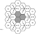
- An example is given in Fig. 3 .
- the compensating cells can be selected to be cells 1, 4, and 7.
- Another example would be cells 1-9.
- the determination of the compensating cells can be made using a multitude of different approaches, some of which include:
- each UE will report a neighbor that has sufficient high quality and which may serve as a candidate for HO.
- a list of candidate neighbors, to participate in the compensating cells can be determined.
- the suitability of a neighbor can be established.
- supporting cells S can be defined as the strongest neighbors of the cells C. The cells S can be determined using the same method that is used for determining the cells C for the outage cell. For example, if the compensating cells C are cells 1, 4, and 7, then the supporting cells are cells 10, 11, 2, 3, 15, 16, 5, 6, 20, 21, 8, and 9.
- the set of cells where P 0 is adjusted includes at least the supporting cells S .
- the compensating cells C can also be adapted as described above.
- P 0 typically constitutes of a cell specific nominal component and a UE specific component.
- the cell specific nominal component of P 0 is reduced in a supporting cell. This means that also UEs that have a relatively high path loss to a compensating cell reduce their uplink transmit power density. This can potentially have a negative impact on the quality, as UEs with high path loss to the compensating cell will not generate significant uplink inter-cell interference to the compensating cell.
- the system makes use of UE-reports (e.g. RSRP measurements) to identify the UEs in a supporting cell that are close (have a relatively low path loss) to a compensating cell C.
- UE-reports e.g. RSRP measurements
- These identified UEs will generate significant uplink inter-cell interference to the compensating cell C. Only the P 0 of these identified UEs are adjusted and other UEs that have a relatively high path loss to the compensating cell C are controlled to maintain their P 0 or not reduce their P 0 as much.
- the parameter P 0,min can be set such that the uplink SINR is sufficient for establishing a basic connection with the network.
- the parameter P 0,min can for example be determined such that::
- the parameter P 0,min is based on the UL SINR as follows.
- SINR min be the minimum tolerable UL SINR, based on e.g., the lowest MCS.
- the received signal power S at the base station must thus satisfy S ⁇ SINR min ⁇ N 0 + I max where I max is the maximum UL inter-cell interference that can be observed.
- I max is the maximum UL inter-cell interference that can be observed.
- the parameter I max can be obtained using different methods, e.g.,
- I max can be adjusted. This can for example be based on the relation between the pre-outage P 0 and the current P 0 .
- the power control loop given above also contains a fractional path loss component governed by ⁇ , which enables trading off cell edge throughput versus cell throughput or capacity.
- the inter-cell interference in the vicinity of the outage cells can be decreased by lowering ⁇ in the supporting cells. This reduces the inter-cell interference to the compensating cells and provides higher capability for the compensating cells to cover the area in outage.
- the cell outage compensation can be triggered by a suitable network node, for example a network manager (NM) node or a domain manager (DM) node.
- a triggering event can cause such a node to signal to the cells concerned and the cells can be instructed to participate in the compensation or in the supporting network by the NM or DM.
- the tuning of P 0 and alpha can also be performed in a network node such as a NM or DM. In this case necessary measurements, e.g., quality and inter-cell interference can be to be sent over the Itf-N interface.
- a radio base station e.g. eNodeB
- the radio base station associated with a first cell Once a the radio base station associated with a first cell has identified its compensation network it informs each second cell in its compensation network, through e.g. the X2 interface, that if an outage occurs then the second cells in the compensating network are to start compensating for the outage. This means that the second cells start compensating when they have detected that the first cell is in outage.
- Each second cell in the compensation network then informs the third cells in the supporting network to also participate in the compensation. Again this can be done using for example the X2 interface.
- the first base station which serves the first cell when the first cell is in outage, the first base station which serves the first cell maintains X2 communication to other cells. Thereby, the first base station can upon detection of the first cell outage signal to the second cells in the compensation network to start compensating. Again, each second cell in the compensation network then informs the third cells in the supporting network to also participate in the compensation.
- Fig. 4 is a flowchart illustrating some procedural steps performed during automated compensation of a cell/sector outage.
- a step 401 it is determined that a cell/sector outage exists.
- uplink power control parameters in an area in the vicinity of the cell/sector in outage are adjusted to compensate for the outage detected in step 401.
- Fig. 5 is a view of a device 501 for performing automated compensation of a cell/sector outage.
- the device comprises a micro processor 503 operating on a set of computer program instructions stored on a memory 505 of the device. Execution of the computer program instructions causes the device to perform the different steps of the methods described herein. In particular the computer program instructions can cause the device to adjust uplink power control parameters in an area in the vicinity of a cell/sector in outage to compensate for outage.
- the device 501 can be integrated in or collocated with any suitable radio system node.
- the device 501 can be integrated in or collocated with a node elements (NE), also referred to as eNodeB, a domain manager (DM), also referred to as the operation and support system (OSS), or a network manager (NM).
- NE node elements
- DM domain manager
- OSS operation and support system
- NM network manager
- Using the methods and devices as described herein provides for very little or no human intervention when compensating for outages, and a shorter response time and faster reaction to outages. Overall, the result is an improved network performance with less user dissatisfaction and a less in revenue loss. Also, while the invention has been described in the context of an E-UTRAN system, the invention can be applied in other cellular radio systems as well, for example in an UTRAN system.
Description
- The present invention relates to a method and a device for managing a cellular radio system. In particular the present invention relates to a method and a device for automatically compensating for a failure in a cell of a cellular radio system.
- The architecture of a Long Term Evolution (LTE) system is shown in
Fig. 1 . In LTE the downlink is based on orthogonal frequency division multiplexing (OFDM) while the uplink is based on a single carrier modulation method known as discrete Fourier transform spread OFDM (DFT-S-OFDM, see 3GPP TR 36.300, Evolved Universal Terrestrial Radio Access (E-UTRA) and Evolved Universal Terrestrial Radio Access (E-UTRAN); Overall description;Stage 2, V8.2.0. InFig. 1 the LTE architecture is shown including the logical interfaces between the radio base stations eNBs (X2) and between eNB and MME/S-GW (SI). - Typically, in a communication system, e.g., UTRAN and E-UTRAN, an open-loop power control mechanism is used in the uplink. This is also often supplemented with a closed-loop part which is not described herein. A common power control loop employed in communication systems, e.g., LTE see 3GPP TS 36.213. E-UTRA; Physical layer procedures, is given by:

- PSD is the power spectral density of the Uplink (UL) transmission
- P0 is the desired received power density
- PL is the path loss, including shadowing and antenna gains
- α is the path loss compensation fraction, where
- ∘ α =1 gives fair performance with optimum cell edge performance (full path loss compensation)
- ∘ α <1 trading cell edge performance for higher cell throughput
- P0 is a parameter, which can be composed of the sum of a cell specific nominal component and a UE specific component. As such it is possible to adjust P0 for the individual UEs within one cell.
- In
Fig. 2 an exemplary management system is shown. The node elements (NE), also referred to as eNodeB (E-UTRAN) or NodeB (UTRAN), are managed by a domain manager (DM), also referred to as the operation and support system (OSS). A DM may further be managed by a network manager (NM). Two NEs can be interfaced by X2 in case of E-UTRAN, whereas the interface between two DMs is referred to as Itf-P2P. - A vision in the ongoing Evolved Universal Terrestrial Radio Access Network (E-UTRAN) standardization work is that the new system is self-organizing in as many aspects as possible, see e.g. NGMN, "Operator Use Cases related to Self Organising Networks," ver. 1.53, 2007-04-16 and Third Generation Partnership Project (3GPP) technical Report TR 32.816, Study on Management of E-UTRAN and SAE.
- One aspect that benefits from self-organization is automatic cell outage compensation. In current wireless communication systems there are situations when a whole base station or part of the base station (e.g. a sector/cell of a sectorized base station) is in outage due to hardware/software failures. When in outage the cell/base station cannot support any users in its vicinity and if these users cannot connect to another base station in the neighborhood then a coverage hole is created. For the operators of wireless access networks this is an undesirable consequence as potential revenue is missed from the unsupported traffic and also customer satisfaction is damaged.
- Common practice today is that the wireless operators aim at repairing the malfunctioning cell/base stations as soon as possible (thereby restoring the original coverage).
- As set out above conventional network managements systems can generate coverage "holes" in the event of a cell/sector outage. This is undesired as potential revenue is missed from the unsupported traffic and also customer satisfaction is damaged. This is particularly critical for services with a negotiated quality such as a guaranteed bit rate.
- Also
US5852778A "Method and system for providing communications service to a coverage hole" describes a communications service to a coverage hole in a DS-CDMA cellular communication system involving an OMC determining the configuration of the transmitters in adjacent cells to the coverage hole. The OMC then selects at least one, but less than all of the transmitters to increase power of a pilot channel. - The method described in
US5852778A is gross grained and can cause interference problems. DocumentsUS2008/064361 A1 , "INFSO-ICT-216284 - D2.1 - Use Cases for Self-Organising Networks" and "NGMN Informative List of SON Use Cases v. 1.23" describe similar approaches asUS5752778A . Hence, there exist a need for an improved method and a system that automatically can compensate for an outage in a cellular radio system. - It is an object of the present invention to overcome or at least reduce some of the problems described above.
This object and others are obtained by the method and device as described herein and as set out in the independent claims. Thus, by adjusting parameters of uplink power control in order to tradeoff coverage versus quality, improved methods and devices for compensating for a coverage hole, which can result from a cell/sector outage are provided. The uplink power control parameters can be continuously optimized in response to traffic and network characteristics thereby providing for an optimized performance degradation in cells surrounding the coverage hole.
In accordance with one embodiment a method for automated compensation of a cell/sector outage is provided. Upon determination of a cell/sector outage uplink power control parameters are adjusted in an area in the vicinity of the cell/sector in outage to decrease uplink inter-cell interference and to increase the uplink Signal to Interference and Noise Ratio (SINR) for user equipments in the cell/sector in outage which are power-limited. In accordance with one embodiment the adjusted uplink control parameters are one or many of the desired received power density and/or the pathloss compensation fraction; or a parameter corresponding to the desired received power density and/or the pathloss compensation fraction.
In accordance with one embodiment a list of cells to adjust the power control parameters in, is determined by simulations, or measurements of the number of times user equipments report a certain neighbor and /or information regarding the strength of this particular neighbor, and/or a rate of handovers to a certain neighbor.
In accordance with one embodiment the desired received power density is computed as a function of observed uplink and downlink quality over a time window, outage target uplink and downlink quality, current and historical power density values, and an allowed power density power value range.
In accordance with one embodiment the outage compensation is triggered by a network manager node or a domain manager node, and where cells are instructed to participate in a compensation or supporting network by the network manager node or the domain manager node.
In accordance with one embodiment the outage compensation is triggered by a radio base station.
In accordance with one embodiment the outage compensation is based on an operator policy governing the actions taken when adjusting uplink power control parameters.
In accordance with one embodiment a device for automated compensation of a cell/sector outage is provided. The device can comprise means for determining a cell/sector outage means for adjusting uplink power control parameters in an area in the vicinity of the cell/sector in outage upon determining the cell/sector outage to decrease uplink inter-cell interference and to increase the uplink Signal to Interference and Noise Ratio (SINR) for user equipments in the cell/sector in outage which are power-limited. The adjusted uplink control parameters can be one or many of the desired received power density for all or a subset of user equipments in the cell/sector and/or the pathloss compensation fraction for all or a subset of user equipments in the cell/sector; or a parameter corresponding to the desired received power density for all or a subset of user equipments in the cell/sector and/or the pathloss compensation fraction for all or a subset of user equipments in the cell/sector.
In accordance with one embodiment the device further comprising means for determining a list of cells, to adjust the power control parameters in, by receiving measurements of the number of times user equipments report a neighbor and/or information regarding the strength of this particular neighbor, and/or a rate of handovers to a certain neighbor. - In accordance with one embodiment the device further comprises means for computing the desired received power density as a function of observed uplink and downlink quality over a time window, outage target uplink and downlink quality, current and historical power density values, and an allowed power density power value range.
- In accordance with one embodiment the device, when outage compensation is triggered by a network manager node or a domain manager node, is further configured to instruct cells to participate in a compensation or supporting network by transmitting a message from the network manager node or the domain manager node.
- In accordance with one embodiment the device, when outage compensation is triggered by a radio base station, is further configured to instruct cells to participate in a compensation or supporting network by transmitting a message from the radio base station.
- In accordance with one embodiment the device further comprises means for basing the outage compensation on an operator policy governing the actions taken when adjusting uplink power control parameters.
- The invention also extends to a device for controlling parameters of uplink power control in accordance with the methods described herein. The device can be computer implemented by a micro processor operating on a set of computer program instructions stored on a memory of the device. Execution of the computer program instructions causes the device to perform the different steps of the methods.
- The method and device can be used in the field of automated mitigation of the negative effects from cell and/or base station outage (e.g. due to hardware/software failure) via compensation actions from the neighboring cells. In particular a method and a device for modifying uplink power control parameters are provided such that coverage and quality, in terms of UE throughput and/or service quality in general, is balanced according to an operator policy.
- The present invention will now be described in more detail by way of non-limiting examples and with reference to the accompanying drawings, in which:
-
Fig. 1 is a general view of an LTE radio system, -
Fig. 2 is a view illustrating a cellular radio system management architecture, -
Fig. 3 is a view illustrating a compensation and supporting network for cells in outage, -
Fig. 4 is a view illustrating some procedural steps performed when compensating for an outage, and -
Fig. 5 is a view of a device for compensation for an outage. - A main goal of cell outage management is to minimize the network performance degradation when a cell is in outage through quick detection and compensation measures. This is performed by automatic adjustment of network parameters in surrounding cells in order to meet the operator's performance requirements based on coverage and other quality indicators, e.g., throughput, to the largest possible extent.
- Altering the radio parameters of the neighboring cells means that some of the user equipments (UEs) served by those cells may be affected. This should be taken into account and an appropriate balance between the quality/coverage offered to the outage area and the unavoidable performance degradation experienced in the surrounding cells, should be achieved. This balance can be controlled and enforced by means of an operator policy that governs the actions taken by the cell outage compensation function.
- Below the quality Q, is defined in terms of end user perceived quality, e.g., 10th-percentile of User Equipment (UE) throughput. The quality term also encompasses the negotiated service quality for admitted users, which for example can correspond to a guaranteed bit rate or a guaranteed latency over some time. In this context, some users may be best effort users in the sense that the perceived quality and service experience depend on the available resources without any guarantees. The quality Q can also mean the fraction of the users that meet the negotiated service quality.
- In accordance with the present invention uplink power control parameters are adjusted in response to an outage in a cell of a cellular radio system to compensate for the hole created by the outage. Below a radio base station eNodeB or its sectors that is not operational is referred to as an outage cell.
- In accordance with one embodiment uplink power control parameters, such as, P0 and α in
equation 1 above, are adjusted in the vicinity of the radio base station (eNodeB) or sector(s) in outage, in order to decrease the uplink inter-cell interference and thereby to increase the uplink Signal to interference and Noise Ratio (SINR) for the UEs in the outage area which are power-limited. - In accordance with one embodiment P0 and α are tuned in response to receiving information of a neighboring outage cell. Hereby the uplink coverage is improved and as such the outage area resulting from the cell outage can decrease in size. Each cell in the vicinity of outage cell(s) can be adapted to continuously measure quality indicators, e.g., 10th-percentile of the downlink and uplink throughput, or fulfillment of negotiated service quality, and adjusts P0 and α such that the quality indicator is equal to or above a certain threshold which can be referred to as the outage target quality. In case of negotiated services, the outage target quality can be either complete fulfillment of the negotiated service quality or a fraction of the services.
- In accordance with one embodiment let QDL and QUL denote the quality in the DL and UL, respectively. Assume further that each cell has an outage target quality QT,DL for the downlink and QT,UL for the uplink, which may be defined in terms of UE throughput, e.g. 10th-percentile UE throughput or fulfillment of negotiated service quality or some other suitable definition. Essentially, the following must hold during an outage QDL ≥ QT,DL and QDL ≥ QT,UL. As a result the coverage is maximized under the constraints that the quality indicator is greater or equal to the specified outage target quality.
- Below some additional detailed examples are given
- First, refer to the cells C, which are best capable of providing coverage over the area previously served by the outage cells, as the compensating cells. An example is given in
Fig. 3 . InFig. 3 an outage area is shown by the striped area in the middle. In this example, the compensating cells can be selected to becells - The determination of the compensating cells can be made using a multitude of different approaches, some of which include:
- Simulation or predictions
- Network measurements, e.g., Handover (HO) rates
- UE reports, e.g., Reference Signal Received Power (RSRP) and Reference Signal Received Quality (RSRQ)
- For example, each UE will report a neighbor that has sufficient high quality and which may serve as a candidate for HO. By measuring the number of times the UEs report a certain neighbor as well as including information regarding the strength of this particular neighbor (using e.g., RSRP or RSRQ measurements), a list of candidate neighbors, to participate in the compensating cells, can be determined. Further, by considering other network-oriented mobility measurements, e.g. HO rate, the suitability of a neighbor can be established. Further, supporting cells S can be defined as the strongest neighbors of the cells C. The cells S can be determined using the same method that is used for determining the cells C for the outage cell. For example, if the compensating cells C are
cells cells - By altering P0 the quality in each cell is changed. In general, decreasing P0 results in a decrease in quality and vice versa. The basic approach works as follows and is executed for each cell in the vicinity of the outage cells. The uplink quality and downlink quality in each cell are continuously measured, whereby P0 is decreased under the constraint that (QDL > QT,DL) AND (QUL > QT,UL) AND (P0 > P0,min)
where P0,min is the minimum tolerable P0.
There are several ways of setting P0 such that above specified constraint is satisfied. One example embodiment is as follows: - If QDL > QT,DL AND QUL > QT,UL then


In general, P0 can be computed as a function of observed uplink and downlink quality over a time window, outage target uplink and downlink quality, current and historical P0 values, and an allowed P0 value range [P0,min, P0,max]. - In accordance with one embodiment, the set of cells where P0 is adjusted includes at least the supporting cells S. Hereby it is possible to decrease the uplink inter-cell interference to the compensating cells C and, thus, increasing the ability of C to cover the area in outage. Further, P0 in the compensating cells C can also be adapted as described above.
- As described above P0 typically constitutes of a cell specific nominal component and a UE specific component. By altering the cell specific nominal component all UEs in the cell are affected. Assume that the cell specific nominal component of P0 is reduced in a supporting cell. This means that also UEs that have a relatively high path loss to a compensating cell reduce their uplink transmit power density. This can potentially have a negative impact on the quality, as UEs with high path loss to the compensating cell will not generate significant uplink inter-cell interference to the compensating cell.
- In accordance with one embodiment the system makes use of UE-reports (e.g. RSRP measurements) to identify the UEs in a supporting cell that are close (have a relatively low path loss) to a compensating cell C. These identified UEs will generate significant uplink inter-cell interference to the compensating cell C. Only the P0 of these identified UEs are adjusted and other UEs that have a relatively high path loss to the compensating cell C are controlled to maintain their P0 or not reduce their P0 as much.
- The parameter P0,min can be set such that the uplink SINR is sufficient for establishing a basic connection with the network. The parameter P0,min can for example be determined such that::
- The UL SINR is higher or equal to a threshold which supports the lowest Modulation and Coding Scheme (MCS), and/or
- A minimum bit rate can be obtained
- In one embodiment, the parameter P0,min is based on the UL SINR as follows. Let SINRmin be the minimum tolerable UL SINR, based on e.g., the lowest MCS. The received signal power S at the base station must thus satisfy


- based on historic measurements of inter-cell interference, and/or
- simulations and/or predictions, and/or
- predictions of future traffic variations
- It is noted that a changed inter-cell characteristics can occur when altering P0. Since P0 is decreased and, as such, the UL inter-cell interference is also decreased, then the observed (historic) Imax will typically be greater than the inter-cell interference obtained with lower P0 during an outage. As such this overestimation will typically not cause any problems. However, in accordance with one embodiment, Imax can be adjusted. This can for example be based on the relation between the pre-outage P0 and the current P0.
- The power control loop given above also contains a fractional path loss component governed by α, which enables trading off cell edge throughput versus cell throughput or capacity. The inter-cell interference in the vicinity of the outage cells can be decreased by lowering α in the supporting cells. This reduces the inter-cell interference to the compensating cells and provides higher capability for the compensating cells to cover the area in outage.
- The cell outage compensation can be triggered by a suitable network node, for example a network manager (NM) node or a domain manager (DM) node. A triggering event can cause such a node to signal to the cells concerned and the cells can be instructed to participate in the compensation or in the supporting network by the NM or DM. Further, the tuning of P0 and alpha can also be performed in a network node such as a NM or DM. In this case necessary measurements, e.g., quality and inter-cell interference can be to be sent over the Itf-N interface.
- In accordance with another embodiment, a radio base station, e.g. eNodeB, can be configured to during nominal operation, i.e., when there are no outages, identify its compensation network by using for example UE or network measurements. Once a the radio base station associated with a first cell has identified its compensation network it informs each second cell in its compensation network, through e.g. the X2 interface, that if an outage occurs then the second cells in the compensating network are to start compensating for the outage. This means that the second cells start compensating when they have detected that the first cell is in outage. Each second cell in the compensation network then informs the third cells in the supporting network to also participate in the compensation. Again this can be done using for example the X2 interface.
- In yet another embodiment, when the first cell is in outage, the first base station which serves the first cell maintains X2 communication to other cells. Thereby, the first base station can upon detection of the first cell outage signal to the second cells in the compensation network to start compensating. Again, each second cell in the compensation network then informs the third cells in the supporting network to also participate in the compensation.
-
Fig. 4 is a flowchart illustrating some procedural steps performed during automated compensation of a cell/sector outage. First, in astep 401, it is determined that a cell/sector outage exists. Next, in astep 403, uplink power control parameters in an area in the vicinity of the cell/sector in outage are adjusted to compensate for the outage detected instep 401. -
Fig. 5 is a view of adevice 501 for performing automated compensation of a cell/sector outage. The device comprises amicro processor 503 operating on a set of computer program instructions stored on amemory 505 of the device. Execution of the computer program instructions causes the device to perform the different steps of the methods described herein. In particular the computer program instructions can cause the device to adjust uplink power control parameters in an area in the vicinity of a cell/sector in outage to compensate for outage. - The
device 501 can be integrated in or collocated with any suitable radio system node. In particular thedevice 501 can be integrated in or collocated with a node elements (NE), also referred to as eNodeB, a domain manager (DM), also referred to as the operation and support system (OSS), or a network manager (NM). - Using the methods and devices as described herein provides for very little or no human intervention when compensating for outages, and a shorter response time and faster reaction to outages. Overall, the result is an improved network performance with less user dissatisfaction and a less in revenue loss. Also, while the invention has been described in the context of an E-UTRAN system, the invention can be applied in other cellular radio systems as well, for example in an UTRAN system.
Claims (14)
- A method for automated compensation of a cell/sector outage, the method comprising the steps of:- determining (401) a cell/sector outage, and- upon determining the cell/sector outage, compensating the cell/sector outage by adjusting (403) uplink power control parameters in an area in a vicinity of the cell/sector in outage to decrease uplink inter-cell interference and to increase the uplink Signal to Interference and Noise Ratio, SINR, for user equipments in the cell/sector in outage which are power-limited.
- The method according to claim 1, wherein the adjusted uplink control parameters are one or many a desired received power density for all or a subset of user equipments in the cell/sector and/or a pathloss compensation fraction for all or a subset of user equipments in the cell/sector; or a parameter corresponding to the desired received power density for all or a subset of user equipments in the cell/sector and/or the pathloss compensation fraction for all or a subset of user equipments in the cell/sector.
- The method according to any of claims 1-2, wherein a list of cells, to adjust the power control parameters in, is determined by simulations, or measurements of a number of times user equipments report a certain neighbor and/or information regarding a strength of this particular neighbor, and/or a rate of handovers to a certain neighbor.
- The method according to any of claims 2-3, wherein the desired received power density is computed as a function of observed uplink and downlink quality over a time window, outage target uplink and downlink quality, current and historical power density values, and an allowed power density power value range.
- The method according to any of claims 1-4, wherein outage compensation is triggered by a network manager node or a domain manager node, and where cells are instructed to participate in a compensation or supporting network by the network manager node or the domain manager node.
- The method according to any of claims 1-4, wherein outage compensation is triggered by a radio base station.
- The method according to any of claims 1-6, wherein outage compensation is based on an operator policy governing the actions taken when adjusting uplink power control parameters.
- A device (501) for automated compensation of a cell/sector outage, the device comprising:- means (503) for determining a cell/sector outage, and- means (503) for compensating the cell/sector outage by adjusting uplink power control parameters in an area in a vicinity of the cell/sector in outage upon determining the cell/sector outage to decrease uplink inter-cell interference and to increase the uplink Signal to Interference and Noise Ratio, SINR, for a user equipment in the cell/sector in outage which are power-limited.
- The device according to claim 8, wherein the adjusted uplink control parameters are one or many of a desired received power density for all or a subset of user equipments in the cell/sector and/or a pathloss compensation fraction for all or a subset of user equipments in the cell/sector; or a parameter corresponding to the desired received power density for all or a subset of user equipments in the cell/sector and/or the pathloss compensation fraction for all or a subset of user equipments in the cell/sector.
- The device according to any of claims 8-9, further comprising means (503) for determining a list of cells, to adjust the power control parameters in, by receiving measurements of a number of times user equipments report a neighbor and/or information regarding a strength of this particular neighbor, and/or a rate of handovers to a certain neighbor.
- The device according to any of claims 8-10, further comprising means (503) for computing the desired received power density as a function of observed uplink and downlink quality over a time window, outage target uplink and downlink quality, current and historical power density values, and an allowed power density power value range.
- The device according to any of claims 8-11, when outage compensation is triggered by a network manager node or a domain manager node, the device further being configured to instruct cells to participate in a compensation or supporting network by transmitting a message from the network manager node or the domain manager node.
- The device according to any of claims 8-11, when outage compensation is triggered by a radio base station, the device further being configured to instruct cells to participate in a compensation or supporting network by transmitting a message from the radio base station.
- The device according to any of claims 8-13, further comprising means (503) for basing the outage compensation on an operator policy governing the actions taken when adjusting uplink power control parameters.
Applications Claiming Priority (2)
| Application Number | Priority Date | Filing Date | Title |
|---|---|---|---|
| US30559110P | 2010-02-18 | 2010-02-18 | |
| PCT/SE2010/050341 WO2011102767A1 (en) | 2010-02-18 | 2010-03-29 | Compensating for coverage holes in a cellular radio system |
Publications (3)
| Publication Number | Publication Date |
|---|---|
| EP2537359A1 EP2537359A1 (en) | 2012-12-26 |
| EP2537359A4 EP2537359A4 (en) | 2015-06-03 |
| EP2537359B1 true EP2537359B1 (en) | 2018-03-07 |
Family
ID=44483180
Family Applications (1)
| Application Number | Title | Priority Date | Filing Date |
|---|---|---|---|
| EP10846254.0A Active EP2537359B1 (en) | 2010-02-18 | 2010-03-29 | Compensating for coverage holes in a cellular radio system |
Country Status (3)
| Country | Link |
|---|---|
| US (1) | US8903375B2 (en) |
| EP (1) | EP2537359B1 (en) |
| WO (1) | WO2011102767A1 (en) |
Families Citing this family (16)
| Publication number | Priority date | Publication date | Assignee | Title |
|---|---|---|---|---|
| RU2522175C2 (en) | 2008-12-03 | 2014-07-10 | Интердиджитал Пэйтент Холдингз, Инк. | Uplink power headroom reporting for carrier aggregation |
| CN103781163B (en) | 2009-02-09 | 2017-07-04 | 交互数字专利控股公司 | The method and WTRU of up-link power control are carried out in WTRU |
| KR101811114B1 (en) | 2009-10-01 | 2017-12-20 | 인터디지탈 패튼 홀딩스, 인크 | Power control methods and apparatus |
| WO2013049769A1 (en) * | 2011-09-30 | 2013-04-04 | Interdigital Patent Holdings, Inc. | Multipoint transmission in wireless communication |
| WO2013136813A1 (en) | 2012-03-15 | 2013-09-19 | 日本電気株式会社 | Wireless communications system, wireless station, network operation management device, and network repair method |
| JP6332633B2 (en) | 2012-03-15 | 2018-05-30 | 日本電気株式会社 | Wireless communication system, wireless station, network operation management apparatus, and network restoration method |
| CN102811469B (en) * | 2012-07-25 | 2018-08-07 | 南京中兴软件有限责任公司 | A kind of Poewr control method and device |
| EP2883406B1 (en) | 2012-08-09 | 2019-06-05 | Telefonaktiebolaget LM Ericsson (publ) | Method and network node for supporting compensation of cell outage in a cellular communications network |
| CN102883357B (en) * | 2012-09-07 | 2016-02-10 | 清华大学 | A kind of for the cell interrupt compensation method in self-organizing network |
| JP6244009B2 (en) | 2013-04-03 | 2017-12-06 | インターデイジタル パテント ホールディングス インコーポレイテッド | Method and apparatus for controlling uplink transmit power based on accumulated transmit power control commands and corresponding uplink subframe sets |
| US9844001B2 (en) * | 2013-08-07 | 2017-12-12 | Telefonaktiebolaget Lm Ericsson (Publ) | System and method for coverage compensation in a communication system |
| US9888479B2 (en) * | 2013-10-22 | 2018-02-06 | Collision Communications, Inc | Method and system for improving efficiency in a cellular communications network |
| US10212670B2 (en) * | 2014-09-10 | 2019-02-19 | Telefonaktiebolaget Lm Ericsson (Publ) | Method and network node for obtaining nominal power and pathloss compensation factor of a power control process |
| EP3041283B1 (en) | 2014-12-30 | 2019-05-29 | Comptel Corporation | Prediction of failures in cellular radio access networks and scheduling of preemptive maintenance |
| US9960957B2 (en) * | 2015-07-29 | 2018-05-01 | Netapp, Inc. | Methods for prioritizing failover of logical interfaces (LIFs) during a node outage and devices thereof |
| KR102154764B1 (en) * | 2016-10-04 | 2020-09-10 | 릴라이언스 지오 인포컴 리미티드 | System and method for mitigating coverage holes from coverage area |
Family Cites Families (18)
| Publication number | Priority date | Publication date | Assignee | Title |
|---|---|---|---|---|
| EP0765586B1 (en) | 1995-04-12 | 2006-09-13 | Motorola, Inc. | Method and system for providing communications service to a coverage hole |
| GB9517439D0 (en) | 1995-08-25 | 1995-10-25 | Esselte Dymo Nv | Printing apparatus |
| US6477376B1 (en) * | 1997-12-23 | 2002-11-05 | At&T Wireless Services, Inc. | Method for designing wireless communications cell sites using uplink parameters |
| US7301926B1 (en) * | 2003-04-04 | 2007-11-27 | Airespace, Inc. | Automatic coverage hole detection in computer network environments |
| WO2006010958A2 (en) | 2004-07-30 | 2006-02-02 | Andrew Richardson | Power control in a local network node (lnn) |
| FR2875077B1 (en) * | 2004-09-09 | 2006-12-08 | Nortel Networks Ltd | METHOD AND DEVICE FOR CONTROLLING THE TRANSMIT POWER OF A MOBILE TERMINAL IN A CELLULAR RADIO SYSTEM, AND TERMINAL ADAPTED TO THE IMPLEMENTATION OF THE METHOD |
| FI20055032A0 (en) | 2005-01-25 | 2005-01-25 | Nokia Corp | Method for reducing interference of an indoor cell in a cellular wireless telecommunication system |
| EP1938636B1 (en) * | 2005-09-30 | 2014-07-30 | Telecom Italia S.p.A. | Method for planning a cellular mobile telecommunications network |
| US7603136B2 (en) * | 2005-11-08 | 2009-10-13 | Honeywell International, Inc. | System and method to perform stable distributed power control in a wireless network |
| US7826820B2 (en) * | 2006-09-08 | 2010-11-02 | Telefonaktiebolaget Lm Ericsson (Publ) | Non-homogenous telecommunications base stations |
| US8050629B2 (en) * | 2007-10-22 | 2011-11-01 | Motorola Mobility, Inc. | Optimizing power settings in a communication system to mitigate interference |
| WO2009122776A1 (en) * | 2008-04-02 | 2009-10-08 | 日本電気株式会社 | Control device, communication system, resource allocation method, and recording medium containing the program |
| US8271014B2 (en) * | 2008-08-11 | 2012-09-18 | Qualcomm Incorporated | Automated parameter adjustment to compensate self adjusting transmit power and sensitivity level at the node B |
| EP2342925A1 (en) * | 2008-09-30 | 2011-07-13 | Spidercloud Wireless, Inc. | Methods and apparatus for generating, reporting and/or using interference cancellation information |
| EP2217027B1 (en) * | 2009-02-05 | 2012-06-20 | Mitsubishi Electric R&D Centre Europe B.V. | Method and a device for adjusting the transmission power of signals |
| US8095143B2 (en) * | 2009-02-13 | 2012-01-10 | Telefonaktiebolaget L M Ericsson | Random access channel (RACH) reconfiguration for temporarily extended cell coverage |
| US20110130137A1 (en) * | 2009-12-01 | 2011-06-02 | Alcatel-Lucent Usa Inc. | Outage Recovery In Wireless Networks |
| US20110176497A1 (en) * | 2010-01-20 | 2011-07-21 | Nandu Gopalakrishnan | Inter-cell interference coordination and power control scheme for downlink transmissions |
-
2010
- 2010-03-29 US US13/522,872 patent/US8903375B2/en active Active
- 2010-03-29 EP EP10846254.0A patent/EP2537359B1/en active Active
- 2010-03-29 WO PCT/SE2010/050341 patent/WO2011102767A1/en active Application Filing
Non-Patent Citations (1)
| Title |
|---|
| SIEMENS, 3GPP DRAFT; GP-050140, 3RD GENERATION PARTNERSHIP PROJECT (3GPP), MOBILE COMPETENCE CENTRE ; 650, ROUTE DES LUCIOLES ; F-06921 SOPHIA-ANTIPOLIS CEDEX ; FRANCE, vol. TSG GERAN, no. Tampa; 20050119, 19 January 2005 (2005-01-19), XP050012954 * |
Also Published As
| Publication number | Publication date |
|---|---|
| US20120295611A1 (en) | 2012-11-22 |
| WO2011102767A1 (en) | 2011-08-25 |
| EP2537359A1 (en) | 2012-12-26 |
| US8903375B2 (en) | 2014-12-02 |
| EP2537359A4 (en) | 2015-06-03 |
Similar Documents
| Publication | Publication Date | Title |
|---|---|---|
| EP2537359B1 (en) | Compensating for coverage holes in a cellular radio system | |
| EP2269415B1 (en) | Estimating and limiting inter-cell interference | |
| US9781685B2 (en) | Self-adaptive coverage of wireless networks | |
| US8515353B2 (en) | Method and arrangement in a radio base station, in a radio communications network | |
| JP5642164B2 (en) | Wireless communication system, wireless base station, and communication control method | |
| US8849340B2 (en) | Methods and devices for reducing interference in an uplink | |
| US9838925B2 (en) | Method and a network node for determining an offset for selection of a cell of a first radio network node | |
| EP2815605B1 (en) | Methods and devices for adjusting resource management procedures in heterogeneous communication networks based on cell information | |
| US20110255514A1 (en) | Method and apparatus of communication | |
| US20120108245A1 (en) | Energy Reduction in Cooperating Radio Access Systems | |
| US20130273919A1 (en) | Handover control method, control apparatus, adjustment apparatus, and non-transitory computer readable medium | |
| US9356832B2 (en) | Method and arrangement for optimization of network element settings | |
| US20120307745A1 (en) | Method And Apparatus Of Fractional Power Control In Wireless Communication Networks | |
| US20140323119A1 (en) | Method of and apparatus for service coverage management in a radio communication network | |
| US9516629B2 (en) | Method and network node for supporting compensation of cell outage in a cellular communications network | |
| US9445324B2 (en) | Method and arrangement in a wireless communication network for determining a type of handover | |
| EP2760237A1 (en) | Network Node and Method to adjust user association in HetNets | |
| US10517034B2 (en) | Uplink-aware serving cell selection | |
| EP2836004A1 (en) | Methods and apparatuses for determining a policy for reporting a cell performance indicator | |
| Calin | WLC20-4: Adaptive Neighbor List Management in Wireless Communication Systems |
Legal Events
| Date | Code | Title | Description |
|---|---|---|---|
| PUAI | Public reference made under article 153(3) epc to a published international application that has entered the european phase |
Free format text: ORIGINAL CODE: 0009012 |
|
| 17P | Request for examination filed |
Effective date: 20120613 |
|
| AK | Designated contracting states |
Kind code of ref document: A1 Designated state(s): AT BE BG CH CY CZ DE DK EE ES FI FR GB GR HR HU IE IS IT LI LT LU LV MC MK MT NL NO PL PT RO SE SI SK SM TR |
|
| DAX | Request for extension of the european patent (deleted) | ||
| RA4 | Supplementary search report drawn up and despatched (corrected) |
Effective date: 20150504 |
|
| RIC1 | Information provided on ipc code assigned before grant |
Ipc: H04W 52/22 20090101ALI20150424BHEP Ipc: H04W 52/34 20090101ALI20150424BHEP Ipc: H04W 24/02 20090101ALI20150424BHEP Ipc: H04W 52/24 20090101ALI20150424BHEP Ipc: H04W 16/10 20090101AFI20150424BHEP Ipc: H04W 52/36 20090101ALI20150424BHEP Ipc: H04W 28/04 20090101ALI20150424BHEP Ipc: H04W 24/04 20090101ALI20150424BHEP Ipc: H04W 52/14 20090101ALI20150424BHEP Ipc: H04W 28/18 20090101ALI20150424BHEP |
|
| STAA | Information on the status of an ep patent application or granted ep patent |
Free format text: STATUS: EXAMINATION IS IN PROGRESS |
|
| 17Q | First examination report despatched |
Effective date: 20170208 |
|
| REG | Reference to a national code |
Ref country code: DE Ref legal event code: R079 Ref document number: 602010049107 Country of ref document: DE Free format text: PREVIOUS MAIN CLASS: H04W0016100000 Ipc: H04W0024080000 |
|
| GRAP | Despatch of communication of intention to grant a patent |
Free format text: ORIGINAL CODE: EPIDOSNIGR1 |
|
| STAA | Information on the status of an ep patent application or granted ep patent |
Free format text: STATUS: GRANT OF PATENT IS INTENDED |
|
| RIC1 | Information provided on ipc code assigned before grant |
Ipc: H04W 28/18 20090101ALI20170908BHEP Ipc: H04W 52/34 20090101ALI20170908BHEP Ipc: H04W 52/22 20090101ALI20170908BHEP Ipc: H04W 24/08 20090101AFI20170908BHEP Ipc: H04W 52/14 20090101ALI20170908BHEP Ipc: H04W 52/24 20090101ALI20170908BHEP Ipc: H04W 24/02 20090101ALI20170908BHEP Ipc: H04W 36/00 20090101ALI20170908BHEP Ipc: H04W 52/36 20090101ALI20170908BHEP |
|
| INTG | Intention to grant announced |
Effective date: 20170927 |
|
| GRAS | Grant fee paid |
Free format text: ORIGINAL CODE: EPIDOSNIGR3 |
|
| GRAA | (expected) grant |
Free format text: ORIGINAL CODE: 0009210 |
|
| STAA | Information on the status of an ep patent application or granted ep patent |
Free format text: STATUS: THE PATENT HAS BEEN GRANTED |
|
| AK | Designated contracting states |
Kind code of ref document: B1 Designated state(s): AT BE BG CH CY CZ DE DK EE ES FI FR GB GR HR HU IE IS IT LI LT LU LV MC MK MT NL NO PL PT RO SE SI SK SM TR |
|
| REG | Reference to a national code |
Ref country code: GB Ref legal event code: FG4D |
|
| REG | Reference to a national code |
Ref country code: CH Ref legal event code: EP Ref country code: AT Ref legal event code: REF Ref document number: 977837 Country of ref document: AT Kind code of ref document: T Effective date: 20180315 |
|
| REG | Reference to a national code |
Ref country code: IE Ref legal event code: FG4D |
|
| REG | Reference to a national code |
Ref country code: DE Ref legal event code: R096 Ref document number: 602010049107 Country of ref document: DE |
|
| REG | Reference to a national code |
Ref country code: NL Ref legal event code: MP Effective date: 20180307 |
|
| REG | Reference to a national code |
Ref country code: LT Ref legal event code: MG4D |
|
| PG25 | Lapsed in a contracting state [announced via postgrant information from national office to epo] |
Ref country code: FI Free format text: LAPSE BECAUSE OF FAILURE TO SUBMIT A TRANSLATION OF THE DESCRIPTION OR TO PAY THE FEE WITHIN THE PRESCRIBED TIME-LIMIT Effective date: 20180307 Ref country code: NO Free format text: LAPSE BECAUSE OF FAILURE TO SUBMIT A TRANSLATION OF THE DESCRIPTION OR TO PAY THE FEE WITHIN THE PRESCRIBED TIME-LIMIT Effective date: 20180607 Ref country code: HR Free format text: LAPSE BECAUSE OF FAILURE TO SUBMIT A TRANSLATION OF THE DESCRIPTION OR TO PAY THE FEE WITHIN THE PRESCRIBED TIME-LIMIT Effective date: 20180307 Ref country code: LT Free format text: LAPSE BECAUSE OF FAILURE TO SUBMIT A TRANSLATION OF THE DESCRIPTION OR TO PAY THE FEE WITHIN THE PRESCRIBED TIME-LIMIT Effective date: 20180307 Ref country code: ES Free format text: LAPSE BECAUSE OF FAILURE TO SUBMIT A TRANSLATION OF THE DESCRIPTION OR TO PAY THE FEE WITHIN THE PRESCRIBED TIME-LIMIT Effective date: 20180307 Ref country code: CY Free format text: LAPSE BECAUSE OF FAILURE TO SUBMIT A TRANSLATION OF THE DESCRIPTION OR TO PAY THE FEE WITHIN THE PRESCRIBED TIME-LIMIT Effective date: 20180307 |
|
| REG | Reference to a national code |
Ref country code: AT Ref legal event code: MK05 Ref document number: 977837 Country of ref document: AT Kind code of ref document: T Effective date: 20180307 |
|
| PG25 | Lapsed in a contracting state [announced via postgrant information from national office to epo] |
Ref country code: BG Free format text: LAPSE BECAUSE OF FAILURE TO SUBMIT A TRANSLATION OF THE DESCRIPTION OR TO PAY THE FEE WITHIN THE PRESCRIBED TIME-LIMIT Effective date: 20180607 Ref country code: GR Free format text: LAPSE BECAUSE OF FAILURE TO SUBMIT A TRANSLATION OF THE DESCRIPTION OR TO PAY THE FEE WITHIN THE PRESCRIBED TIME-LIMIT Effective date: 20180608 Ref country code: SE Free format text: LAPSE BECAUSE OF FAILURE TO SUBMIT A TRANSLATION OF THE DESCRIPTION OR TO PAY THE FEE WITHIN THE PRESCRIBED TIME-LIMIT Effective date: 20180307 Ref country code: LV Free format text: LAPSE BECAUSE OF FAILURE TO SUBMIT A TRANSLATION OF THE DESCRIPTION OR TO PAY THE FEE WITHIN THE PRESCRIBED TIME-LIMIT Effective date: 20180307 |
|
| PG25 | Lapsed in a contracting state [announced via postgrant information from national office to epo] |
Ref country code: PL Free format text: LAPSE BECAUSE OF FAILURE TO SUBMIT A TRANSLATION OF THE DESCRIPTION OR TO PAY THE FEE WITHIN THE PRESCRIBED TIME-LIMIT Effective date: 20180307 Ref country code: EE Free format text: LAPSE BECAUSE OF FAILURE TO SUBMIT A TRANSLATION OF THE DESCRIPTION OR TO PAY THE FEE WITHIN THE PRESCRIBED TIME-LIMIT Effective date: 20180307 Ref country code: NL Free format text: LAPSE BECAUSE OF FAILURE TO SUBMIT A TRANSLATION OF THE DESCRIPTION OR TO PAY THE FEE WITHIN THE PRESCRIBED TIME-LIMIT Effective date: 20180307 Ref country code: IT Free format text: LAPSE BECAUSE OF FAILURE TO SUBMIT A TRANSLATION OF THE DESCRIPTION OR TO PAY THE FEE WITHIN THE PRESCRIBED TIME-LIMIT Effective date: 20180307 Ref country code: RO Free format text: LAPSE BECAUSE OF FAILURE TO SUBMIT A TRANSLATION OF THE DESCRIPTION OR TO PAY THE FEE WITHIN THE PRESCRIBED TIME-LIMIT Effective date: 20180307 |
|
| REG | Reference to a national code |
Ref country code: CH Ref legal event code: PL |
|
| PG25 | Lapsed in a contracting state [announced via postgrant information from national office to epo] |
Ref country code: CZ Free format text: LAPSE BECAUSE OF FAILURE TO SUBMIT A TRANSLATION OF THE DESCRIPTION OR TO PAY THE FEE WITHIN THE PRESCRIBED TIME-LIMIT Effective date: 20180307 Ref country code: SK Free format text: LAPSE BECAUSE OF FAILURE TO SUBMIT A TRANSLATION OF THE DESCRIPTION OR TO PAY THE FEE WITHIN THE PRESCRIBED TIME-LIMIT Effective date: 20180307 Ref country code: AT Free format text: LAPSE BECAUSE OF FAILURE TO SUBMIT A TRANSLATION OF THE DESCRIPTION OR TO PAY THE FEE WITHIN THE PRESCRIBED TIME-LIMIT Effective date: 20180307 Ref country code: SM Free format text: LAPSE BECAUSE OF FAILURE TO SUBMIT A TRANSLATION OF THE DESCRIPTION OR TO PAY THE FEE WITHIN THE PRESCRIBED TIME-LIMIT Effective date: 20180307 |
|
| REG | Reference to a national code |
Ref country code: BE Ref legal event code: MM Effective date: 20180331 Ref country code: DE Ref legal event code: R097 Ref document number: 602010049107 Country of ref document: DE |
|
| REG | Reference to a national code |
Ref country code: IE Ref legal event code: MM4A |
|
| PG25 | Lapsed in a contracting state [announced via postgrant information from national office to epo] |
Ref country code: PT Free format text: LAPSE BECAUSE OF FAILURE TO SUBMIT A TRANSLATION OF THE DESCRIPTION OR TO PAY THE FEE WITHIN THE PRESCRIBED TIME-LIMIT Effective date: 20180709 Ref country code: LU Free format text: LAPSE BECAUSE OF NON-PAYMENT OF DUE FEES Effective date: 20180329 |
|
| PLBE | No opposition filed within time limit |
Free format text: ORIGINAL CODE: 0009261 |
|
| STAA | Information on the status of an ep patent application or granted ep patent |
Free format text: STATUS: NO OPPOSITION FILED WITHIN TIME LIMIT |
|
| PG25 | Lapsed in a contracting state [announced via postgrant information from national office to epo] |
Ref country code: DK Free format text: LAPSE BECAUSE OF FAILURE TO SUBMIT A TRANSLATION OF THE DESCRIPTION OR TO PAY THE FEE WITHIN THE PRESCRIBED TIME-LIMIT Effective date: 20180307 Ref country code: IE Free format text: LAPSE BECAUSE OF NON-PAYMENT OF DUE FEES Effective date: 20180329 Ref country code: MC Free format text: LAPSE BECAUSE OF FAILURE TO SUBMIT A TRANSLATION OF THE DESCRIPTION OR TO PAY THE FEE WITHIN THE PRESCRIBED TIME-LIMIT Effective date: 20180307 |
|
| 26N | No opposition filed |
Effective date: 20181210 |
|
| PG25 | Lapsed in a contracting state [announced via postgrant information from national office to epo] |
Ref country code: BE Free format text: LAPSE BECAUSE OF NON-PAYMENT OF DUE FEES Effective date: 20180331 Ref country code: SI Free format text: LAPSE BECAUSE OF FAILURE TO SUBMIT A TRANSLATION OF THE DESCRIPTION OR TO PAY THE FEE WITHIN THE PRESCRIBED TIME-LIMIT Effective date: 20180307 Ref country code: CH Free format text: LAPSE BECAUSE OF NON-PAYMENT OF DUE FEES Effective date: 20180331 Ref country code: LI Free format text: LAPSE BECAUSE OF NON-PAYMENT OF DUE FEES Effective date: 20180331 |
|
| PG25 | Lapsed in a contracting state [announced via postgrant information from national office to epo] |
Ref country code: FR Free format text: LAPSE BECAUSE OF NON-PAYMENT OF DUE FEES Effective date: 20180507 |
|
| PG25 | Lapsed in a contracting state [announced via postgrant information from national office to epo] |
Ref country code: MT Free format text: LAPSE BECAUSE OF NON-PAYMENT OF DUE FEES Effective date: 20180329 |
|
| PG25 | Lapsed in a contracting state [announced via postgrant information from national office to epo] |
Ref country code: TR Free format text: LAPSE BECAUSE OF FAILURE TO SUBMIT A TRANSLATION OF THE DESCRIPTION OR TO PAY THE FEE WITHIN THE PRESCRIBED TIME-LIMIT Effective date: 20180307 |
|
| PG25 | Lapsed in a contracting state [announced via postgrant information from national office to epo] |
Ref country code: HU Free format text: LAPSE BECAUSE OF FAILURE TO SUBMIT A TRANSLATION OF THE DESCRIPTION OR TO PAY THE FEE WITHIN THE PRESCRIBED TIME-LIMIT; INVALID AB INITIO Effective date: 20100329 |
|
| PG25 | Lapsed in a contracting state [announced via postgrant information from national office to epo] |
Ref country code: MK Free format text: LAPSE BECAUSE OF NON-PAYMENT OF DUE FEES Effective date: 20180307 |
|
| PG25 | Lapsed in a contracting state [announced via postgrant information from national office to epo] |
Ref country code: IS Free format text: LAPSE BECAUSE OF FAILURE TO SUBMIT A TRANSLATION OF THE DESCRIPTION OR TO PAY THE FEE WITHIN THE PRESCRIBED TIME-LIMIT Effective date: 20180707 |
|
| PGFP | Annual fee paid to national office [announced via postgrant information from national office to epo] |
Ref country code: GB Payment date: 20230327 Year of fee payment: 14 Ref country code: DE Payment date: 20230329 Year of fee payment: 14 |