EP2537041B1 - Mr-apparatur mit autofokussierendem bewegungsmonitorsystem - Google Patents
Mr-apparatur mit autofokussierendem bewegungsmonitorsystem Download PDFInfo
- Publication number
- EP2537041B1 EP2537041B1 EP10706519.5A EP10706519A EP2537041B1 EP 2537041 B1 EP2537041 B1 EP 2537041B1 EP 10706519 A EP10706519 A EP 10706519A EP 2537041 B1 EP2537041 B1 EP 2537041B1
- Authority
- EP
- European Patent Office
- Prior art keywords
- lens
- camera lens
- magnetic resonance
- camera
- optical
- Prior art date
- Legal status (The legal status is an assumption and is not a legal conclusion. Google has not performed a legal analysis and makes no representation as to the accuracy of the status listed.)
- Not-in-force
Links
- 230000033001 locomotion Effects 0.000 title claims description 14
- 230000003287 optical effect Effects 0.000 claims description 26
- 230000003044 adaptive effect Effects 0.000 claims description 23
- 239000000696 magnetic material Substances 0.000 claims description 14
- 229920001296 polysiloxane Polymers 0.000 claims description 12
- 239000012528 membrane Substances 0.000 claims description 10
- 238000005452 bending Methods 0.000 claims description 8
- 239000007788 liquid Substances 0.000 claims description 7
- 238000012544 monitoring process Methods 0.000 claims description 7
- 229920000642 polymer Polymers 0.000 claims description 3
- 230000001276 controlling effect Effects 0.000 claims description 2
- 230000001105 regulatory effect Effects 0.000 claims description 2
- 238000005259 measurement Methods 0.000 description 11
- 238000005086 pumping Methods 0.000 description 7
- 239000003550 marker Substances 0.000 description 6
- 239000012530 fluid Substances 0.000 description 4
- 229910052782 aluminium Inorganic materials 0.000 description 3
- XAGFODPZIPBFFR-UHFFFAOYSA-N aluminium Chemical compound [Al] XAGFODPZIPBFFR-UHFFFAOYSA-N 0.000 description 3
- 238000013461 design Methods 0.000 description 3
- 239000011521 glass Substances 0.000 description 3
- 238000007654 immersion Methods 0.000 description 3
- 239000007787 solid Substances 0.000 description 3
- 239000000758 substrate Substances 0.000 description 3
- RYGMFSIKBFXOCR-UHFFFAOYSA-N Copper Chemical compound [Cu] RYGMFSIKBFXOCR-UHFFFAOYSA-N 0.000 description 2
- 238000012937 correction Methods 0.000 description 2
- 230000003993 interaction Effects 0.000 description 2
- 101100117236 Drosophila melanogaster speck gene Proteins 0.000 description 1
- 238000013459 approach Methods 0.000 description 1
- 229910052802 copper Inorganic materials 0.000 description 1
- 239000010949 copper Substances 0.000 description 1
- 239000011889 copper foil Substances 0.000 description 1
- 238000001514 detection method Methods 0.000 description 1
- 238000011161 development Methods 0.000 description 1
- 238000003745 diagnosis Methods 0.000 description 1
- 239000011888 foil Substances 0.000 description 1
- 238000003384 imaging method Methods 0.000 description 1
- 238000009434 installation Methods 0.000 description 1
- 229910052751 metal Inorganic materials 0.000 description 1
- 239000002184 metal Substances 0.000 description 1
- 238000005457 optimization Methods 0.000 description 1
- 230000000087 stabilizing effect Effects 0.000 description 1
- 238000007740 vapor deposition Methods 0.000 description 1
Images

Classifications
-
- G—PHYSICS
- G01—MEASURING; TESTING
- G01R—MEASURING ELECTRIC VARIABLES; MEASURING MAGNETIC VARIABLES
- G01R33/00—Arrangements or instruments for measuring magnetic variables
- G01R33/20—Arrangements or instruments for measuring magnetic variables involving magnetic resonance
- G01R33/28—Details of apparatus provided for in groups G01R33/44 - G01R33/64
- G01R33/283—Intercom or optical viewing arrangements, structurally associated with NMR apparatus
-
- G—PHYSICS
- G02—OPTICS
- G02B—OPTICAL ELEMENTS, SYSTEMS OR APPARATUS
- G02B27/00—Optical systems or apparatus not provided for by any of the groups G02B1/00 - G02B26/00, G02B30/00
- G02B27/40—Optical focusing aids
-
- A—HUMAN NECESSITIES
- A61—MEDICAL OR VETERINARY SCIENCE; HYGIENE
- A61B—DIAGNOSIS; SURGERY; IDENTIFICATION
- A61B17/00—Surgical instruments, devices or methods
- A61B2017/00681—Aspects not otherwise provided for
- A61B2017/00694—Aspects not otherwise provided for with means correcting for movement of or for synchronisation with the body
-
- A—HUMAN NECESSITIES
- A61—MEDICAL OR VETERINARY SCIENCE; HYGIENE
- A61B—DIAGNOSIS; SURGERY; IDENTIFICATION
- A61B34/00—Computer-aided surgery; Manipulators or robots specially adapted for use in surgery
- A61B34/20—Surgical navigation systems; Devices for tracking or guiding surgical instruments, e.g. for frameless stereotaxis
- A61B2034/2046—Tracking techniques
- A61B2034/2055—Optical tracking systems
-
- A—HUMAN NECESSITIES
- A61—MEDICAL OR VETERINARY SCIENCE; HYGIENE
- A61B—DIAGNOSIS; SURGERY; IDENTIFICATION
- A61B90/00—Instruments, implements or accessories specially adapted for surgery or diagnosis and not covered by any of the groups A61B1/00 - A61B50/00, e.g. for luxation treatment or for protecting wound edges
- A61B90/36—Image-producing devices or illumination devices not otherwise provided for
- A61B90/37—Surgical systems with images on a monitor during operation
- A61B2090/374—NMR or MRI
-
- G—PHYSICS
- G01—MEASURING; TESTING
- G01R—MEASURING ELECTRIC VARIABLES; MEASURING MAGNETIC VARIABLES
- G01R33/00—Arrangements or instruments for measuring magnetic variables
- G01R33/20—Arrangements or instruments for measuring magnetic variables involving magnetic resonance
- G01R33/44—Arrangements or instruments for measuring magnetic variables involving magnetic resonance using nuclear magnetic resonance [NMR]
- G01R33/48—NMR imaging systems
- G01R33/54—Signal processing systems, e.g. using pulse sequences ; Generation or control of pulse sequences; Operator console
- G01R33/56—Image enhancement or correction, e.g. subtraction or averaging techniques, e.g. improvement of signal-to-noise ratio and resolution
- G01R33/565—Correction of image distortions, e.g. due to magnetic field inhomogeneities
- G01R33/56509—Correction of image distortions, e.g. due to magnetic field inhomogeneities due to motion, displacement or flow, e.g. gradient moment nulling
-
- G—PHYSICS
- G01—MEASURING; TESTING
- G01R—MEASURING ELECTRIC VARIABLES; MEASURING MAGNETIC VARIABLES
- G01R33/00—Arrangements or instruments for measuring magnetic variables
- G01R33/20—Arrangements or instruments for measuring magnetic variables involving magnetic resonance
- G01R33/44—Arrangements or instruments for measuring magnetic variables involving magnetic resonance using nuclear magnetic resonance [NMR]
- G01R33/48—NMR imaging systems
- G01R33/54—Signal processing systems, e.g. using pulse sequences ; Generation or control of pulse sequences; Operator console
- G01R33/56—Image enhancement or correction, e.g. subtraction or averaging techniques, e.g. improvement of signal-to-noise ratio and resolution
- G01R33/567—Image enhancement or correction, e.g. subtraction or averaging techniques, e.g. improvement of signal-to-noise ratio and resolution gated by physiological signals, i.e. synchronization of acquired MR data with periodical motion of an object of interest, e.g. monitoring or triggering system for cardiac or respiratory gating
Definitions
- MR magnetic resonance
- Movements of measurement objects, in particular of living beings such as patients during a magnetic resonance ( MR) scan lead to artefacts, which often render the data useless for medical use. Especially in the medical field, this leads to a more difficult diagnosis and reduction of patient throughput.
- MR magnetic resonance
- the first successful 3 D real-time motion correction was done by Hennig, Zaitsev and Speck et. al. [ Zaitsev M, Dold C, Sakas G, Hennig J, and Bacon O. Neuroimage, 2006; 31 (3): 1038-1050 and Bacon O, Hennig J, and Zaitsev M. Magn. Reson. Mater. Phy., 2006; 19 (2): 55-61 ] developed.
- the system for detecting the movement was located outside the bore within the MRI room (distance approx. 4 m).
- the motion detection marker was located on the patient's head and was targeted and recorded.
- the monitoring data from a stereo camera was transferred directly from a hardware control unit to the MRI imager and corrected.
- the object of the present invention in contrast, is to develop an MR apparatus of the type described at the outset with an optical movement monitoring system for detecting uncontrolled movements of the measurement object, in particular of patients to be examined, during an MR scan, which is within the bore of the MR magnet system is arranged, the MR measurement not negatively affected and despite a large focus range has a high optical resolution.
- RF radio frequency
- the marker is permanently focused with an autofocus.
- autofocusing the marker By autofocusing the marker, the depth of field can be significantly reduced and thus the optical resolution and the measurement accuracy can be significantly increased.
- the measured motion parameters are used for real-time correction of the MRI data.
- the system is inside the magnetic core. The compatibility of the individual components such as camera chip and autofocus optics must be ensured in view of the strong magnetic field (up to 11.7 T), the switched gradient fields and the strong radio frequency field usually 64 to 500 MHz).
- At least one adaptive lens is arranged.
- Such an adaptive lens allows a particularly compact design of the autofocus system.
- the bore is made very small, so that there is very little space available to accommodate a camera lens.
- the adaptive lens is a silicone membrane lens. All components of the lens are made of non-magnetic material. Therefore, it is particularly suitable for use in an MR apparatus. An alternative possibility would be to make the adaptive lens from a solid polymer rather than silicone.
- the adaptive lens includes a lens chamber, a pumping chamber and a piezoelectric bending transducer, each made of non-magnetic material. This allows the change of the focal length of the lens without electric motors.
- piezoelectric traveling wave motors as they are installed in SLR cameras. These are also MR compatible.
- the adaptive lens is filled with an optically transparent liquid, in particular an immersion oil.
- the liquid provides the necessary refractive index.
- the amount of liquid in the lens chamber determines the focal length of the adaptive lens.
- the lens is filled with two liquids of different optical properties.
- the autofocus system is surrounded by an HF shield impenetrable RF shielding.
- a metal foil of non-magnetic material such as aluminum or copper is suitable.
- a solid enclosure made of aluminum or a metallic, non-magnetic vapor deposition of the outer surfaces of the autofocus system are possible.
- the autofocus system comprises in a further embodiment of the invention, a diaphragm made of non-magnetic material and at least two achromatic lenses.
- a further embodiment of the invention is characterized in that the light entering the camera lens from the object to be measured encloses an angle of 90 ° with respect to the optical axis of the objective lenses, and that the light then enters the lens via a 45 ° mirror of non-magnetic material optical plane of the camera lens is deflected.
- the length of the camera lens is not so relevant in this embodiment.
- an increase in the working distance leads to a reduction in the optical field angle, resulting in the reduction of optical errors.
- An alternative embodiment provides that the light entering the camera lens from the measurement object enters parallel to the optical axis of the objective lenses.
- the mirror is saved as an optical element, thus reducing the length of the camera lens.
- control unit for controlling or regulating the autofocus system.
- the control unit will be advantageously provided outside the bore and therefore does not necessarily require the use of non-magnetic materials. However, with suitable shielding, it is also conceivable to provide the control unit also within the bore of the magnet.
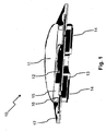
- Fig. 1 shows a schematic spatial representation of an embodiment of the inventive adaptive silicone membrane lens 10, which was originally developed for the mobile electronics market. It consists of two components: lens chamber 12 and pumping chamber 13, which are connected on a glass substrate 17 with each other.
- the lens chamber 12 is filled with an optically transparent liquid, in particular an immersion oil, and is composed of a silicone membrane 11 with a support ring 15 .
- the pumping chamber 13, in which the lens fluid is located, consists of a piezoelectric bending transducer 14 embedded in silicone .
- the fluid exchange between the pumping chamber 13 and the lens chamber 12 is achieved via openings in the glass substrate 17. If a voltage is applied to the piezo-bending transducer 14, then its inner region bulges upward and displaces lens fluid from the pumping chamber 13 into the lens chamber 12. This results in an increasing bulging of the silicone membrane 11 and thus a reduction in the lens focal length.
- Fig. 2 shows a schematic representation of a possible optical structure of the camera lens 20.
- the light emanating from the measuring object 28 hits a mirror 21 arranged at an angle of 45 ° of non-magnetic material. This deflects the incident light by about 90 ° in a direction parallel to the optical axis of the lens system.
- the light first passes through a plano-concave lens 26 which focuses the light.
- a shutter 24 is arranged at the focal point of the plano-concave lens 26 (or shortly before or after) a shutter 24 is arranged.
- An adaptive lens 25 always ensures optimal imaging of the measurement object 28 on the camera 27, which can be embodied for example as a CCD camera.
- Two achromatic lenses 22, 23 ensure that the light hits the camera 27 in parallel.
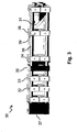
- One possible embodiment of the camera lens 30 is in Fig. 3 shown schematically spatially.
- Concrete boundary conditions for the wide-angle objective in the embodiment shown are an object size of 60 ⁇ 4 mm 2 , an image size on the camera chip (6.54 ⁇ 5.23 mm 2 ), the object distance (distance between objective and object) and the length of the objective .
- the ZEMAX ® raytracing software was used as support.
- Each individual optical component ie mirror 31, plano-concave lens 36, aperture 34, adaptive lens 35 and the achromatic lenses 32, 33
- All mounting plates are in turn connected to each other with four rods 38, for example of aluminum, to which the camera 37 is attached.
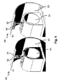
- Fig. 4 shows two possible arrangements of the camera lens 44 according to the invention, 54 in the bore 43, 53 of the MR magnet 42, 52 of an MR apparatus 40, 50. It should be noted that the camera lens 44, 54 being within the bore 43, 53 of the MR Magnets 42, 52 is mounted, but not in the measuring volume 41, 51, in which the measuring object is positioned protrudes.
- Fig. 4 a shows an MR apparatus 40 with a linear camera lens 44, which is characterized by a small length.
- the MR apparatus 50 in Fig. 4b) includes a camera lens 54 with mirror as shown in FIG Fig. 2 is shown schematically.
- This camera lens is distinguished by the fact that it is less extensible in the direction of the measuring volume 51 and can thus also be mounted in MR magnet systems with high magnetic field strengths and a small bore, without projecting into the measuring volume.
Landscapes
- Physics & Mathematics (AREA)
- General Physics & Mathematics (AREA)
- Optics & Photonics (AREA)
- Condensed Matter Physics & Semiconductors (AREA)
- Lens Barrels (AREA)
- Magnetic Resonance Imaging Apparatus (AREA)
Description
- Die Erfindung betrifft eine Magnetresonanz (=MR) Apparatur mit einem MR-Magnetsystem zur Erzeugung eines homogenen Magnetfelds, das eine Bohrung zur Aufnahme eines Messobjektes aufweist, sowie mit einem optischen Bewegungsmonitorsystem zur Erfassung von Bewegungen des Messobjektes, umfassend eine innerhalb der Bohrung angeordnete, optische Kamera mit einem Kameraobjektiv, sowie eine Vorrichtung zur Übertragung von Monitoringdaten an einen außerhalb des MR- Magnetsystems vorgesehenen Bildwandler.
- Eine solche Apparatur ist aus
US 2009/0209846 A1 , sowie aus Qin et al. [Magn. Reson. Med., 2009; 62: 924-934] bekannt. - Bewegungen von Messobjekten, vor allem von Lebewesen wie etwa Patienten während eines Magnetresonanz (=MR) -scans führen zu Artefakten, welche die Daten etwa für die medizinische Verwendung oft nutzlos machen. Insbesondere im medizinischen Bereich führt dies zu einer Erschwerung der Diagnostik und Reduktion des Patientendurchsatzes.
- Es wurden bereits unterschiedliche Systeme für optisches Bewegungsmonitoring entwickelt, welche jedoch aufgrund der erschwerten Handhabung nicht kommerzialisiert wurden.
- Die erste erfolgreiche 3 D Echtzeit Bewegungskorrektur wurde von Hennig, Zaitsev und Speck et. al. [Zaitsev M, Dold C, Sakas G, Hennig J, und Speck O. Neuroimage, 2006; 31(3): 1038-1050 und Speck O, Hennig J, und Zaitsev M. Magn. Reson. Mater. Phy., 2006; 19(2): 55-61] entwickelt.
- Das System zur Erfassung der Bewegung befand sich dabei außerhalb der Bohrung innerhalb des MRT-Raums (Abstand ca. 4 m). Der Marker zur Bewegungserfassung befand sich dabei am Kopf des Patienten und wurde direkt angepeilt und erfasst. Zur Korrektur der Bewegung wurden die Monitoringdaten einer Stereokamera direkt von einer Hardwarekontrolleinheit an den MRT-Bildwandler übergeben und korrigiert.
- Ähnliche Lösungsansätze sind aus
US 7,498,811 B2 ,US 2005/0054910 A1 undUS 2007/0280508 A1 bekannt. - Aufgrund des langen optischen Pfades zwischen Stereokamera und Marker ist die Justage und Kalibrierung derartiger optischer Systeme sehr aufwendig.
- Aus diesem Grund wurde vom Qin et al. [Magn. Reson. Med., 2009; 62: 924-934] und Aksoy et al. [Aksoy M, Newbould R, Straka M, Holdsworth S, Skare S, Santos J, Bammer R. Proceedings of the 16th Scientific Meeting, Int. Soc. Magn. Reson. Med., Toronto, Canada, 2008, p 3120] eine MR-kompatible Kamera entwickelt, welche sich im Magnet-Kern direkt oberhalb des Markers befindet. Die permanente Fokussierung des Markers wurde mit einer kleinen Lochblende, welche eine sehr große Schärfentiefe aufweist, realisiert. Der große Schärfenbereich, führt jedoch zur Reduktion der optischen Auflösung und somit zu einer deutlichen Verringerung der Messgenauigkeit.
-
US 2009/0209846 A1 stellt nun eine Weiterentwicklung dieser Idee dar. Dabei wurden zwei CCD Kameras mittels Kupferfolie vom Hochfrequenzfeld der MR-Apparatur abgeschirmt und auf einer der Magnetspulen einer 1,5T MR-Apparatur angebracht. Aus der CCD Kamera wurden magnetische Komponenten weitgehend, jedoch nicht vollständig, entfernt. Auch hier wurde eine Lochblende für einen großen Schärfenbereich verwendet. - Handelsübliche Autofokussysteme, wie sie etwa in Barcode-Lesegeräten eingebaut werden, verwenden Tauchspulenantriebe. Diese aufgrund der magnetischen Materialien nicht MR-kompatiblen Aktoren sind für den Einsatz innerhalb im Magnetkern eines Magneten vollkommen ungeeignet.
- Schneider, Mueller und Wallrabe entwickelten 2008 eine Silikon-Membran-Linse [Journal of Optics A - Pure and Applied Optics, 2008] mit dem Ziel, eine preisgünstige und kompakte adaptive Linse für Mobil-Elektronik-Geräte, wie etwa Mobiltelefone, zu erhalten.
- Aufgabe der vorliegenden Erfindung ist es demgegenüber, eine MR-Apparatur der eingangs beschriebenen Art mit einem optischen Bewegungsmonitoringsystem zur Erfassung von unkontrollierten Bewegungen des Messobjekts, insbesondere von zu untersuchenden Patienten, während eines MR-Scans zu entwickeln, welches innerhalb der Bohrung des MR-Magnetsystems angeordnet ist, die MR-Messung nicht negativ beeinflusst und trotz eines großen Schärfenbereichs eine hohe optische Auflösung aufweist.
- Diese Aufgabe wird erfindungsgemäß auf ebenso überraschend einfache wie wirkungsvolle Weise dadurch gelöst, dass das Kameraobjektiv ein Autofokussystem aus nicht-magnetischem Material umfasst, dass das Autofokussystem Hochfrequenz (=HF) Felder weder absorbiert noch reflektiert noch emittiert, dass im Autofokussystem mindestens eine adaptive Linse angeordnet ist, dass die adaptive Linse eine Silikon-Membran-Linse ist oder aus einem Voll-Polymer hergestellt ist, und dass die adaptive Linse eine Linsenkammer, eine Pumpkammer und einen piezoelektronischen Biegewandler umfasst, die jeweils aus nicht-magnetischem Material hergestellt sind, wobei zur Brennweiteneinstellung mittels des Biegewandlers Flüssigkeit von der einen kammer in die andere kammer verdrängt werden kann.
- Im Gegensatz zum Stand der Technik wird beim erfindungsgemäßen System der Marker permanent mit einem Autofokus scharf gestellt. Durch die Autofokussierung des Markers kann die Schärfentiefe deutlich reduziert und somit die optische Auflösung bzw. die Messgenauigkeit wesentlich erhöht werden. Die gemessenen Bewegungsparameter werden für eine Echtzeitkorrektur der MRT-Daten verwendet. Zur Visualisierung des bewegten Körpers befindet sich das System innerhalb des Magnetkerns. Dabei muss die Kompatibilität der Einzelkomponenten wie KameraChip und Autofokusoptik im Hinblick auf das starke Magnetfeld (bis zu 11,7 T), den geschalteten Gradientenfeldern sowie des starken Radiofrequenzfelds üblicherweise 64 bis 500 MHz) gewährleistet sein.
- Im Autofokussystem ist mindestens eine adaptive Linse angeordnet. Eine solche adaptive Linse erlaubt eine besonders kompakte Bauweise des Autofokussystems. Insbesondere in MR-Magnetsystemen mit sehr hohen Magnetfeldern ist die Bohrung sehr klein ausgeführt, so dass zum Unterbringen eines Kameraobjektivs nur sehr wenig Raum zur Verfügung steht.
- Bei einer Ausführungsform ist die adaptive Linse eine Silikon-Membran-Linse. Alle Komponenten der Linse bestehen aus nicht-magnetischem Material. Daher eignet sie sich besonders zum Einsatz in einer MR-Apparatur.
Eine alternative Möglichkeit wäre, die adaptive Linse aus einem Voll-Polymer statt aus Silikon herzustellen. - Die adaptive Linse umfasst eine Linsenkammer, eine Pumpkammer und einen piezoelektronischen Biegewandler, die jeweils aus nicht-magnetischem Material hergestellt sind. Dies erlaubt die Veränderung der Brennweite der Linse ohne Elektromotoren.
- Eine alternative Möglichkeit wären piezoelektronische Wanderwellenmotoren, wie sie in Spiegelreflex-Kameras verbaut werden. Auch diese sind MR-kompatibel.
- Zu bevorzugen ist es, wenn die adaptive Linse mit einer optisch transparenten Flüssigkeit, insbesondere einem Immersionsöl, gefüllt ist. Die Flüssigkeit sorgt für den notwendigen Brechungsindex. Die Menge der Flüssigkeit in der Linsenkammer bestimmt die Brennweite der adaptiven Linse.
- Bei einer alternativen Möglichkeit, dem Elektrowetting, wird die Linse mit zwei Flüssigkeiten unterschiedlicher optischer Eigenschaften gefüllt.
- Bei einer weiteren vorteilhaften Ausführungsform der Erfindung ist das Autofokussystem von einer für HF-Felder undurchdringlichen HF-Abschirmeinrichtung umgeben. Dadurch werden die wenigen nicht-magnetischen, aber metallischen Komponenten, wie etwa Strom- und Datenkabel, vor dem HF-Feld abgeschirmt und eine unerwünschte Wechselwirkung vermieden. Wechselwirkungen können zum Beispiel durch das HF-Feld in den Komponenten erzeugte Ströme sein, die im ungünstigsten Fall die Komponente zerstören können.
- Als Abschirmeinrichtung ist eine Metallfolie aus nicht-magnetischem Material, wie etwa Aluminium oder Kupfer, geeignet. Aber auch eine feste Umhüllung aus Aluminium oder eine metallische, nicht-magnetische Bedampfung der äußeren Oberflächen des Autofokussystems sind möglich.
- Das Autofokussystem umfasst bei einer weiteren Ausführungsform der Erfindung eine Blende aus nicht-magnetischem Material sowie mindestens zwei achromatische Linsen.
- Eine weitere Ausführungsform der Erfindung ist dadurch gekennzeichnet, dass das vom Messobjekt aus in das Kameraobjektiv eintretende Licht gegenüber der optischen Achse der Objektivlinsen einen Winkel von 90° einschließt, und dass das Licht anschließend über einen 45° - Spiegel aus nicht-magnetischem Material in die optische Ebene des Kameraobjektivs umgelenkt wird. Auf diese Weise ist eine besonders platzsparende Montage des Kameraobjektivs möglich. Die Baulänge des Kameraobjektivs ist bei dieser Ausführungsform nicht so relevant. Zudem führt eine Vergrößerung des Arbeitsabstands zur Verringerung der optischen Feldwinkel, was die Reduktion optischer Fehler zur Folge hat.
- Eine alternative Ausführungsform sieht vor, dass das vom Messobjekt aus in das Kameraobjektiv eintretende Licht parallel zur optischen Achse der Objektivlinsen eintritt. Hier wird der Spiegel als optisches Element eingespart und so die Baulänge des Kameraobjektivs reduziert.
- Es ist vorteilhaft, wenn eine elektronische Kontrolleinheit zur Steuerung oder Regelung des Autofokussystems vorgesehen ist. Die Kontrolleinheit wird vorteilhafterweise außerhalb der Bohrung vorgesehen sein und erfordert daher nicht notwendig die Verwendung von nicht-magnetischen Materialien. Mit geeigneter Abschirmung ist es jedoch auch denkbar, die Kontrolleinheit ebenfalls innerhalb der Bohrung des Magneten vorzusehen.
- Weitere Vorteile der Erfindung ergeben sich aus der Beschreibung und der Zeichnung. Ebenso können die vorstehend genannten und die weiter aufgeführten Merkmale je für sich oder zu mehreren in beliebigen Kombinationen Verwendung finden. Die gezeigten und beschriebenen Ausführungsformen sind nicht als abschließende Aufzählung zu verstehen, sondern haben vielmehr beispielhaften Charakter für die Schilderung der Erfindung.
- Es zeigen:
- Fig. 1:
- eine schematische räumliche Darstellung einer erfindungsgemäßen adaptiven Silikon-Membran-Linse;
- Fig. 2:
- eine schematische Darstellung des optischen Aufbaus eines erfindungsgemäßen Kameraobjektivs inklusive Strahlengang des vom Messobjekt ausgehenden Lichts;
- Fig. 3:
- eine räumliche schematische Darstellung einer Ausführungsform des erfindungsgemäßen Kameraobjektivs;
- Fig. 4:
- eine schematische Darstellung der Anordnung einer Ausführungsform des erfindungsgemäßen Kameraobjektivs in einer MR-Apparatur, a) in linearer Bauweise ohne Spiegel und b) bei Verwendung eines 45° Spiegels wie in
Fig.2 . -
Fig. 1 zeigt eine schematische räumliche Darstellung einer Ausführungsform der erfindungsgemäßen adaptiven Silikon-Membran-Linse 10, die ursprünglich für den Mobil-Elektronik Markt entwickelt wurde. Sie besteht aus zwei Komponenten: Linsenkammer 12 und Pumpkammer 13, welche auf einem Glassubstrat 17 miteinander verbunden sind. - Die Linsenkammer 12 ist mit einer optisch transparenten Flüssigkeit, insbesondere einem Immersionsöl, gefüllt und setzt sich aus einer Silikonmembran 11 mit Stützring 15 zusammen. Die Pumpkammer 13, in welcher sich auch die Linsenflüssigkeit befindet, besteht aus einem in Silikon eingebetteten piezoelektrischen Biegewandler 14.
- Der Flüssigkeitsaustausch zwischen Pumpkammer 13 und Linsenkammer 12 wird über Öffnungen im Glassubstrat 17 erreicht. Wird am Piezo-Biegewandler 14 eine Spannung angelegt, so wölbt sich dessen innerer Bereich nach oben und verdrängt Linsenflüssigkeit aus der Pumpkammer 13 in die Linsenkammer 12. Das hat eine zunehmende Auswölbung der Silikon-Membran 11 und damit eine Verringerung der Linsenbrennweite zur Folge.
-
Fig. 2 zeigt eine schematische Darstellung eines möglichen optischen Aufbaus des Kameraobjektivs 20. Das vom Messobjekt 28 ausgehende Licht trifft auf einen im Winkel von 45° angeordneten Spiegel 21 aus nicht-magnetischem Material. Dieser lenkt das einfallende Licht um etwa 90° in eine Richtung parallel zur optischen Achse des Linsensystems um. Das Licht passiert zunächst eine plan-konkave Linse 26, die das Licht fokussiert. Im Brennpunkt der plan-konkaven Linse 26 (oder kurz davor oder danach) ist eine Blende 24 angeordnet. Eine adaptive Linse 25 sorgt stets für eine optimale Abbildung des Messobjekts 28 auf die Kamera 27, die beispielsweise als CCD-Kamera ausgeführt sein kann. Zwei achromatische Linsen 22, 23 sorgen dafür, dass das Licht parallel auf die Kamera 27 trifft. - Eine mögliche Ausführung des Kameraobjektivs 30 ist in
Fig. 3 schematisch räumlich dargestellt. Konkrete Randbedingungen für das Weitwinkelobjektiv in der gezeigten Ausführungsform sind eine Objektgröße von 60 x 4 mm2, eine Bildgröße auf dem Kamerachip (6,54 x 5,23 mm2), die Objektweite (Abstand zwischen Objektiv und Objekt) und die Länge des Objektivs. Beim optischen Design des adaptiven Kameraobjektivs 30 wurde zur Unterstützung die Raytracing Software ZEMAX® verwendet. Nach der theoretischen Optimierung des Objektivs wurde dieses aus Linos-Komponenten aufgebaut. Jede einzelne optische Komponente (also Spiegel 31, plan-konkave Linse 36, Blende 34, adaptive Linse 35 und die achromatischen Linsen 32, 33) ist dabei an einer Aufnahmeplatte 39 befestigt. Alle Aufnahmeplatten sind wiederum mit vier Stangen 38, z.B. aus Aluminium miteinander verbunden, an denen auch die Kamera 37 befestigt ist. -
Fig. 4 zeigt zwei mögliche Anordnungen des erfindungsgemäßen Kameraobjektivs 44, 54 in der Bohrung 43, 53 des MR-Magneten 42, 52 einer MR-Apparatur 40, 50. Man beachte, dass das Kameraobjektiv 44, 54 zwar innerhalb der Bohrung 43, 53 des MR-Magneten 42, 52 angebracht ist, jedoch nicht in das Messvolumen 41, 51, in welchem das das Messobjekt positioniert wird, hineinragt. -
Fig. 4 a) zeigt eine MR-Apparatur 40 mit einem linearen Kameraobjektiv 44, welches sich durch eine kleine Baulänge auszeichnet. - Die MR-Apparatur 50 in
Fig. 4 b) umfasst ein Kameraobjektiv 54 mit Spiegel, wie es inFig. 2 schematisch dargestellt ist. Dieses Kameraobjektiv zeichnet sich dadurch aus, dass es weniger in Richtung des Messvolumens 51 ausgedehnt ist und somit auch in MR-Magnetsystemen mit hohen Magnetfeldstärken und kleiner Bohrung angebracht werden kann, ohne in das Messvolumen hineinzuragen. -
10 Adaptive Silikon-Membran-Linse 30 Kameraobjektiv 11 Silikon-Membran 31 Spiegel 12 Linsenkammer 32 Achromatische Linse 13 Pumpkammer 33 Achromatische Linse 14 Piezoelektrischer Biegewandler 34 Blende 15 Stützring 35 Adaptive Linse 16 Stabilisierungsring 36 Plan-konkave Linse 17 Glassubstrat 37 Kamera 38 Halte-Stangen 20 Kameraobjektiv 39 Aufnahmeplatte 21 Spiegel 22 Achromatische Linse (f=200 mm) 40, 50 MR-Apparatur 23 Achromatische Linse (f=40 mm) 41, 51 Messvolumen 24 Blende 42, 52 MR-Magnetsystem 25 Adaptive Linse 43, 53 Bohrung des MR-Magneten 26 Plan-konkave Linse (f=-40 mm) 44 Kameraobjektiv linear 27 Kamera 54 Kameraobjektiv mit Spiegel 28 Messobjekt
Claims (7)
- Magnetresonanz (=MR) Apparatur (40; 50) mit einem MR- Magnetsystem (42; 52) zur Erzeugung eines homogenen Magnetfelds, das eine Bohrung (43; 53) zur Aufnahme eines Messobjektes (28) aufweist, sowie mit einem optischen Bewegungsmonitorsystem zur Erfassung von Bewegungen des Messobjektes (28), umfassend eine innerhalb der Bohrung (43; 53) angeordnete, optische Kamera (27; 37) mit einem Kameraobjektiv (20; 30; 44; 54), sowie eine Vorrichtung zur Übertragung von Monitoringdaten an einen außerhalb des MR- Magnetsystems (42; 52) vorgesehenen Bildwandler,
dadurch gekennzeichnet,
dass das Kameraobjektiv (20; 30; 44; 54) ein Autofokussystem aus nicht-magnetischem Material umfasst,
dass das Autofokussystem Hochfrequenz (=HF) Felder weder absorbiert noch reflektiert noch emittiert,
dass im Autofokussystem mindestens eine adaptive Linse (25; 35) angeordnet ist,
dass die adaptive Linse (25; 35) eine Silikon-Membran-Linse (10) oder aus einem Voll-Polymer hergestellt ist, und
dass die adaptive Linse (25; 35) eine Linsenkammer (12), eine Pumpkammer (13) und einen piezoelektronischen Biegewandler (14) umfasst, die jeweils aus nicht-magnetischem Material hergestellt sind,
wobei zur Brennweiteneinstellung mittels des piezoelektrischen Biegewandlers (14) Flüssigkeit von der einen Kammer in die andere Kammer verdrängt werden kann. - Magnetresonanz-Apparatur nach Anspruch 1, dadurch gekennzeichnet, dass die adaptive Linse (25; 35) mit einer optisch transparenten Flüssigkeit gefüllt ist.
- Magnetresonanz-Apparatur nach einem der vorhergehenden Ansprüche,
dadurch gekennzeichnet, dass das Autofokussystem von einer für HF-Felder undurchdringlichen HF-Abschirmeinrichtung umgeben ist. - Magnetresonanz-Apparatur nach einem der vorhergehenden Ansprüche,
dadurch gekennzeichnet, dass das Autofokussystem eine Blende (24; 34) aus nicht-magnetischem Material sowie mindestens zwei achromatische Linsen (22, 23; 32, 33) umfasst. - Magnetresonanz-Apparatur nach einem der Ansprüche 1 bis 4, dadurch gekennzeichnet, dass das Kameraobjektiv (20; 30; 54) mehrere Objektivlinsen enthält und dass das vom Messobjekt (28) aus in das Kameraobjektiv (20; 30; 54) eintretende Licht gegenüber der optischen Achse der Objektivlinsen (22, 23, 25, 26; 32, 33, 35, 36) einen Winkel von 90° einschließt, und dass das Licht anschließend über einen 45° - Spiegel (21; 31) aus nicht-magnetischem Material in die optische Ebene des Kameraobjektivs (20; 30; 54) umgelenkt wird.
- Magnetresonanz-Apparatur nach einem der Ansprüche 1 bis 4, dadurch gekennzeichnet, dass das Kameraobjektiv (20; 30; 54) mehrere Objektivlinsen enthält und dass das vom Messobjekt (28) aus in das Kameraobjektiv (44) eintretende Licht parallel zur optischen Achse der Objektivlinsen (22, 23, 25, 26; 32, 33, 35, 36) eintritt.
- Magnetresonanz-Apparatur nach einem der vorhergehenden Ansprüche, dadurch gekennzeichnet, dass eine elektronische Kontrolleinheit zur Steuerung oder Regelung des Autofokussystems vorgesehen ist.
Applications Claiming Priority (1)
| Application Number | Priority Date | Filing Date | Title |
|---|---|---|---|
| PCT/EP2010/001050 WO2011100993A1 (de) | 2010-02-19 | 2010-02-19 | Mr-apparatur mit autofokussierendem bewegungsmonitorsystem sowie zugehöriges kameraobjektiv mit adaptiver linse |
Publications (2)
| Publication Number | Publication Date |
|---|---|
| EP2537041A1 EP2537041A1 (de) | 2012-12-26 |
| EP2537041B1 true EP2537041B1 (de) | 2014-04-09 |
Family
ID=42788491
Family Applications (1)
| Application Number | Title | Priority Date | Filing Date |
|---|---|---|---|
| EP10706519.5A Not-in-force EP2537041B1 (de) | 2010-02-19 | 2010-02-19 | Mr-apparatur mit autofokussierendem bewegungsmonitorsystem |
Country Status (2)
| Country | Link |
|---|---|
| EP (1) | EP2537041B1 (de) |
| WO (1) | WO2011100993A1 (de) |
Families Citing this family (2)
| Publication number | Priority date | Publication date | Assignee | Title |
|---|---|---|---|---|
| IL221491A (en) * | 2012-08-15 | 2016-06-30 | Aspect Imaging Ltd | Mri apparatus combined with lightfield camera |
| DE102012216303A1 (de) * | 2012-09-13 | 2014-03-13 | Siemens Aktiengesellschaft | Magnetresonanzaufnahmeeinheit sowie eine Magnetresonanzvorrichtung mit der Magnetresonanzaufnahmeeinheit |
Family Cites Families (4)
| Publication number | Priority date | Publication date | Assignee | Title |
|---|---|---|---|---|
| AU2004203173A1 (en) | 2003-07-14 | 2005-02-03 | Sunnybrook And Women's College And Health Sciences Centre | Optical image-based position tracking for magnetic resonance imaging |
| US7498811B2 (en) | 2005-11-16 | 2009-03-03 | Macfarlane Duncan L | Apparatus and method for patient movement tracking |
| EP2023812B1 (de) | 2006-05-19 | 2016-01-27 | The Queen's Medical Center | Bewegungsverfolgungssystem für adaptive echtzeitabbildung und -spektroskopie |
| US20090209846A1 (en) | 2006-06-28 | 2009-08-20 | Roland Bammer | Apparatus and method for real-time motion-compensated magnetic resonance imaging |
-
2010
- 2010-02-19 EP EP10706519.5A patent/EP2537041B1/de not_active Not-in-force
- 2010-02-19 WO PCT/EP2010/001050 patent/WO2011100993A1/de not_active Ceased
Also Published As
| Publication number | Publication date |
|---|---|
| EP2537041A1 (de) | 2012-12-26 |
| WO2011100993A1 (de) | 2011-08-25 |
Similar Documents
| Publication | Publication Date | Title |
|---|---|---|
| DE102012222375B3 (de) | Magnetresonanzspulenvorrichtung, Magnetresonanzvorrichtung mit der Magnetresonanzspulenvorrichtung sowie ein Verfahren zur Erfassung einer Patientenbewegung | |
| DE102012216303A1 (de) | Magnetresonanzaufnahmeeinheit sowie eine Magnetresonanzvorrichtung mit der Magnetresonanzaufnahmeeinheit | |
| DE10348796B4 (de) | Vorrichtung zur räumlichen Modulation eines Röntgenstrahlbündels und Röntgenbildsystem | |
| EP0475098B1 (de) | Röntgenmikroskop | |
| DE102019219506A1 (de) | System und verfahren zum eichen eines linsensystems mit variabler brennweite unter verwendung eines eichobjekts mit einer ebenen geneigten musterfläche | |
| DE102009027119A1 (de) | Magnetfeldeinheit eines MRT-Systems zur bildgebenden Erfassung eines Kopfbereichs | |
| DE60127025T2 (de) | Verfahren und Gerät zur Bilderzeugung durch Kernresonanz | |
| DE102007029363A1 (de) | Kombinierte Positronenemissions-Magnetresonanz-Tomographie-Vorrichtung | |
| EP4334770B1 (de) | Mikroskopiesystem und verfahren zum betreiben eines mikroskopiesystems | |
| DE10219767B4 (de) | Kernspintomographiegerät mit einer vakuumvergossenen Körperspule | |
| DE10391596B4 (de) | Kapselung eines Magnet-Resonanz-Tomographiegeräts zur Dämpfung niedriger Schallfrequenzen | |
| DE102010008551B4 (de) | Röntgensystem | |
| DE19704696B4 (de) | Gradientspulenvorrichtung und Magnetresonanz-Bilderzeugungsvorrichtung | |
| DE10155464A1 (de) | Beleuchtungseinheit zur Erzeugung von optischen Schnittbildern in transparenten Medien, insbesondere im Auge | |
| EP2537041A1 (de) | Mr-apparatur mit autofokussierendem bewegungsmonitorsystem sowie zugehöriges kameraobjektiv mit adaptiver linse | |
| EP0154624B1 (de) | Einrichtung zum erzeugen vollständiger dreidimensionaler darstellungen eines räumlichen objektes | |
| DE102020205037A1 (de) | Vorrrichtung und Verfahren zur patientenspezifischen Störunterdrückung | |
| DE10228829B4 (de) | Verbindungsvorrichtung zur Lagefixierung einer Gradientenspulenbaugruppe eines Kernspintomographen, Kernspintomograph mit der Verbindungsvorrichtung und Verwendung der Verbindungsvorrichtung | |
| DE102006046734A1 (de) | Verfahren zur Einstellung einer von einem magnetischen Störfeld verschobenen Fokusposition und Röntgenrohre und medizinisches Röntgenaufnahmesystem | |
| DE10200861A1 (de) | Magnetresonanzgerät mit einem Wirbelstromerzeuger | |
| DE19643116C2 (de) | Verfahren und Vorrichtung zur Magnetresonanzuntersuchung | |
| WO2009129802A1 (de) | Verfahren und vorrichtung zum volumetrischen scannen | |
| DE102013208620A1 (de) | Medizinisches Bildgebungssystem, das eine Magnetresonanzbildgebungseinheit und eine Positronen-Emissions-Tomographie-Einheit umfasst | |
| WO2003025609A1 (de) | Magnet-resonanz-tomographiegerät mit lärmunterdrückung durch dämpfung von mechanischen schwingungen | |
| EP1887404B1 (de) | Periskop und Verfahren zur Auslegung einer optischen Übertragungsstrecke in einem Periskop |
Legal Events
| Date | Code | Title | Description |
|---|---|---|---|
| PUAI | Public reference made under article 153(3) epc to a published international application that has entered the european phase |
Free format text: ORIGINAL CODE: 0009012 |
|
| 17P | Request for examination filed |
Effective date: 20120919 |
|
| AK | Designated contracting states |
Kind code of ref document: A1 Designated state(s): AT BE BG CH CY CZ DE DK EE ES FI FR GB GR HR HU IE IS IT LI LT LU LV MC MK MT NL NO PL PT RO SE SI SK SM TR |
|
| DAX | Request for extension of the european patent (deleted) | ||
| 17Q | First examination report despatched |
Effective date: 20130610 |
|
| GRAP | Despatch of communication of intention to grant a patent |
Free format text: ORIGINAL CODE: EPIDOSNIGR1 |
|
| RIC1 | Information provided on ipc code assigned before grant |
Ipc: G01R 33/28 20060101AFI20130826BHEP Ipc: G01R 33/567 20060101ALN20130826BHEP Ipc: G01R 33/565 20060101ALN20130826BHEP Ipc: G02B 27/40 20060101ALI20130826BHEP Ipc: A61B 17/00 20060101ALN20130826BHEP |
|
| INTG | Intention to grant announced |
Effective date: 20130916 |
|
| GRAS | Grant fee paid |
Free format text: ORIGINAL CODE: EPIDOSNIGR3 |
|
| GRAA | (expected) grant |
Free format text: ORIGINAL CODE: 0009210 |
|
| AK | Designated contracting states |
Kind code of ref document: B1 Designated state(s): AT BE BG CH CY CZ DE DK EE ES FI FR GB GR HR HU IE IS IT LI LT LU LV MC MK MT NL NO PL PT RO SE SI SK SM TR |
|
| REG | Reference to a national code |
Ref country code: GB Ref legal event code: FG4D Free format text: NOT ENGLISH |
|
| REG | Reference to a national code |
Ref country code: CH Ref legal event code: EP Ref country code: AT Ref legal event code: REF Ref document number: 661623 Country of ref document: AT Kind code of ref document: T Effective date: 20140415 |
|
| REG | Reference to a national code |
Ref country code: IE Ref legal event code: FG4D Free format text: LANGUAGE OF EP DOCUMENT: GERMAN |
|
| REG | Reference to a national code |
Ref country code: DE Ref legal event code: R096 Ref document number: 502010006600 Country of ref document: DE Effective date: 20140522 |
|
| REG | Reference to a national code |
Ref country code: NL Ref legal event code: VDEP Effective date: 20140409 |
|
| REG | Reference to a national code |
Ref country code: LT Ref legal event code: MG4D |
|
| PG25 | Lapsed in a contracting state [announced via postgrant information from national office to epo] |
Ref country code: NO Free format text: LAPSE BECAUSE OF FAILURE TO SUBMIT A TRANSLATION OF THE DESCRIPTION OR TO PAY THE FEE WITHIN THE PRESCRIBED TIME-LIMIT Effective date: 20140709 Ref country code: IS Free format text: LAPSE BECAUSE OF FAILURE TO SUBMIT A TRANSLATION OF THE DESCRIPTION OR TO PAY THE FEE WITHIN THE PRESCRIBED TIME-LIMIT Effective date: 20140809 Ref country code: LT Free format text: LAPSE BECAUSE OF FAILURE TO SUBMIT A TRANSLATION OF THE DESCRIPTION OR TO PAY THE FEE WITHIN THE PRESCRIBED TIME-LIMIT Effective date: 20140409 Ref country code: BG Free format text: LAPSE BECAUSE OF FAILURE TO SUBMIT A TRANSLATION OF THE DESCRIPTION OR TO PAY THE FEE WITHIN THE PRESCRIBED TIME-LIMIT Effective date: 20140709 Ref country code: GR Free format text: LAPSE BECAUSE OF FAILURE TO SUBMIT A TRANSLATION OF THE DESCRIPTION OR TO PAY THE FEE WITHIN THE PRESCRIBED TIME-LIMIT Effective date: 20140710 Ref country code: NL Free format text: LAPSE BECAUSE OF FAILURE TO SUBMIT A TRANSLATION OF THE DESCRIPTION OR TO PAY THE FEE WITHIN THE PRESCRIBED TIME-LIMIT Effective date: 20140409 Ref country code: FI Free format text: LAPSE BECAUSE OF FAILURE TO SUBMIT A TRANSLATION OF THE DESCRIPTION OR TO PAY THE FEE WITHIN THE PRESCRIBED TIME-LIMIT Effective date: 20140409 |
|
| PG25 | Lapsed in a contracting state [announced via postgrant information from national office to epo] |
Ref country code: SE Free format text: LAPSE BECAUSE OF FAILURE TO SUBMIT A TRANSLATION OF THE DESCRIPTION OR TO PAY THE FEE WITHIN THE PRESCRIBED TIME-LIMIT Effective date: 20140409 Ref country code: HR Free format text: LAPSE BECAUSE OF FAILURE TO SUBMIT A TRANSLATION OF THE DESCRIPTION OR TO PAY THE FEE WITHIN THE PRESCRIBED TIME-LIMIT Effective date: 20140409 Ref country code: PL Free format text: LAPSE BECAUSE OF FAILURE TO SUBMIT A TRANSLATION OF THE DESCRIPTION OR TO PAY THE FEE WITHIN THE PRESCRIBED TIME-LIMIT Effective date: 20140409 Ref country code: ES Free format text: LAPSE BECAUSE OF FAILURE TO SUBMIT A TRANSLATION OF THE DESCRIPTION OR TO PAY THE FEE WITHIN THE PRESCRIBED TIME-LIMIT Effective date: 20140409 Ref country code: LV Free format text: LAPSE BECAUSE OF FAILURE TO SUBMIT A TRANSLATION OF THE DESCRIPTION OR TO PAY THE FEE WITHIN THE PRESCRIBED TIME-LIMIT Effective date: 20140409 |
|
| PG25 | Lapsed in a contracting state [announced via postgrant information from national office to epo] |
Ref country code: PT Free format text: LAPSE BECAUSE OF FAILURE TO SUBMIT A TRANSLATION OF THE DESCRIPTION OR TO PAY THE FEE WITHIN THE PRESCRIBED TIME-LIMIT Effective date: 20140811 |
|
| REG | Reference to a national code |
Ref country code: DE Ref legal event code: R097 Ref document number: 502010006600 Country of ref document: DE |
|
| PG25 | Lapsed in a contracting state [announced via postgrant information from national office to epo] |
Ref country code: CZ Free format text: LAPSE BECAUSE OF FAILURE TO SUBMIT A TRANSLATION OF THE DESCRIPTION OR TO PAY THE FEE WITHIN THE PRESCRIBED TIME-LIMIT Effective date: 20140409 Ref country code: DK Free format text: LAPSE BECAUSE OF FAILURE TO SUBMIT A TRANSLATION OF THE DESCRIPTION OR TO PAY THE FEE WITHIN THE PRESCRIBED TIME-LIMIT Effective date: 20140409 Ref country code: EE Free format text: LAPSE BECAUSE OF FAILURE TO SUBMIT A TRANSLATION OF THE DESCRIPTION OR TO PAY THE FEE WITHIN THE PRESCRIBED TIME-LIMIT Effective date: 20140409 Ref country code: SK Free format text: LAPSE BECAUSE OF FAILURE TO SUBMIT A TRANSLATION OF THE DESCRIPTION OR TO PAY THE FEE WITHIN THE PRESCRIBED TIME-LIMIT Effective date: 20140409 Ref country code: RO Free format text: LAPSE BECAUSE OF FAILURE TO SUBMIT A TRANSLATION OF THE DESCRIPTION OR TO PAY THE FEE WITHIN THE PRESCRIBED TIME-LIMIT Effective date: 20140409 |
|
| PLBE | No opposition filed within time limit |
Free format text: ORIGINAL CODE: 0009261 |
|
| STAA | Information on the status of an ep patent application or granted ep patent |
Free format text: STATUS: NO OPPOSITION FILED WITHIN TIME LIMIT |
|
| 26N | No opposition filed |
Effective date: 20150112 |
|
| PG25 | Lapsed in a contracting state [announced via postgrant information from national office to epo] |
Ref country code: IT Free format text: LAPSE BECAUSE OF FAILURE TO SUBMIT A TRANSLATION OF THE DESCRIPTION OR TO PAY THE FEE WITHIN THE PRESCRIBED TIME-LIMIT Effective date: 20140409 |
|
| REG | Reference to a national code |
Ref country code: DE Ref legal event code: R097 Ref document number: 502010006600 Country of ref document: DE Effective date: 20150112 |
|
| PG25 | Lapsed in a contracting state [announced via postgrant information from national office to epo] |
Ref country code: BE Free format text: LAPSE BECAUSE OF NON-PAYMENT OF DUE FEES Effective date: 20150228 |
|
| PG25 | Lapsed in a contracting state [announced via postgrant information from national office to epo] |
Ref country code: SI Free format text: LAPSE BECAUSE OF FAILURE TO SUBMIT A TRANSLATION OF THE DESCRIPTION OR TO PAY THE FEE WITHIN THE PRESCRIBED TIME-LIMIT Effective date: 20140409 |
|
| PG25 | Lapsed in a contracting state [announced via postgrant information from national office to epo] |
Ref country code: LU Free format text: LAPSE BECAUSE OF FAILURE TO SUBMIT A TRANSLATION OF THE DESCRIPTION OR TO PAY THE FEE WITHIN THE PRESCRIBED TIME-LIMIT Effective date: 20150219 |
|
| REG | Reference to a national code |
Ref country code: CH Ref legal event code: PL |
|
| GBPC | Gb: european patent ceased through non-payment of renewal fee |
Effective date: 20150219 |
|
| PG25 | Lapsed in a contracting state [announced via postgrant information from national office to epo] |
Ref country code: MC Free format text: LAPSE BECAUSE OF FAILURE TO SUBMIT A TRANSLATION OF THE DESCRIPTION OR TO PAY THE FEE WITHIN THE PRESCRIBED TIME-LIMIT Effective date: 20140409 Ref country code: LI Free format text: LAPSE BECAUSE OF NON-PAYMENT OF DUE FEES Effective date: 20150228 Ref country code: CH Free format text: LAPSE BECAUSE OF NON-PAYMENT OF DUE FEES Effective date: 20150228 |
|
| REG | Reference to a national code |
Ref country code: IE Ref legal event code: MM4A |
|
| REG | Reference to a national code |
Ref country code: FR Ref legal event code: ST Effective date: 20151030 |
|
| PG25 | Lapsed in a contracting state [announced via postgrant information from national office to epo] |
Ref country code: IE Free format text: LAPSE BECAUSE OF NON-PAYMENT OF DUE FEES Effective date: 20150219 Ref country code: GB Free format text: LAPSE BECAUSE OF NON-PAYMENT OF DUE FEES Effective date: 20150219 |
|
| PG25 | Lapsed in a contracting state [announced via postgrant information from national office to epo] |
Ref country code: FR Free format text: LAPSE BECAUSE OF NON-PAYMENT OF DUE FEES Effective date: 20150302 |
|
| REG | Reference to a national code |
Ref country code: AT Ref legal event code: MM01 Ref document number: 661623 Country of ref document: AT Kind code of ref document: T Effective date: 20150219 |
|
| PG25 | Lapsed in a contracting state [announced via postgrant information from national office to epo] |
Ref country code: AT Free format text: LAPSE BECAUSE OF NON-PAYMENT OF DUE FEES Effective date: 20150219 |
|
| PG25 | Lapsed in a contracting state [announced via postgrant information from national office to epo] |
Ref country code: MT Free format text: LAPSE BECAUSE OF FAILURE TO SUBMIT A TRANSLATION OF THE DESCRIPTION OR TO PAY THE FEE WITHIN THE PRESCRIBED TIME-LIMIT Effective date: 20140409 |
|
| PG25 | Lapsed in a contracting state [announced via postgrant information from national office to epo] |
Ref country code: HU Free format text: LAPSE BECAUSE OF FAILURE TO SUBMIT A TRANSLATION OF THE DESCRIPTION OR TO PAY THE FEE WITHIN THE PRESCRIBED TIME-LIMIT; INVALID AB INITIO Effective date: 20100219 Ref country code: SM Free format text: LAPSE BECAUSE OF FAILURE TO SUBMIT A TRANSLATION OF THE DESCRIPTION OR TO PAY THE FEE WITHIN THE PRESCRIBED TIME-LIMIT Effective date: 20140409 |
|
| PG25 | Lapsed in a contracting state [announced via postgrant information from national office to epo] |
Ref country code: CY Free format text: LAPSE BECAUSE OF FAILURE TO SUBMIT A TRANSLATION OF THE DESCRIPTION OR TO PAY THE FEE WITHIN THE PRESCRIBED TIME-LIMIT Effective date: 20140409 |
|
| PG25 | Lapsed in a contracting state [announced via postgrant information from national office to epo] |
Ref country code: TR Free format text: LAPSE BECAUSE OF FAILURE TO SUBMIT A TRANSLATION OF THE DESCRIPTION OR TO PAY THE FEE WITHIN THE PRESCRIBED TIME-LIMIT Effective date: 20140409 |
|
| PG25 | Lapsed in a contracting state [announced via postgrant information from national office to epo] |
Ref country code: MK Free format text: LAPSE BECAUSE OF FAILURE TO SUBMIT A TRANSLATION OF THE DESCRIPTION OR TO PAY THE FEE WITHIN THE PRESCRIBED TIME-LIMIT Effective date: 20140409 |
|
| PGFP | Annual fee paid to national office [announced via postgrant information from national office to epo] |
Ref country code: DE Payment date: 20200220 Year of fee payment: 11 |
|
| REG | Reference to a national code |
Ref country code: DE Ref legal event code: R119 Ref document number: 502010006600 Country of ref document: DE |
|
| PG25 | Lapsed in a contracting state [announced via postgrant information from national office to epo] |
Ref country code: DE Free format text: LAPSE BECAUSE OF NON-PAYMENT OF DUE FEES Effective date: 20210901 |