EP2536185A2 - Centralized Bluetooth Device Pairing - Google Patents
Centralized Bluetooth Device Pairing Download PDFInfo
- Publication number
- EP2536185A2 EP2536185A2 EP12171519A EP12171519A EP2536185A2 EP 2536185 A2 EP2536185 A2 EP 2536185A2 EP 12171519 A EP12171519 A EP 12171519A EP 12171519 A EP12171519 A EP 12171519A EP 2536185 A2 EP2536185 A2 EP 2536185A2
- Authority
- EP
- European Patent Office
- Prior art keywords
- user
- wireless device
- pairing
- devices
- phone
- Prior art date
- Legal status (The legal status is an assumption and is not a legal conclusion. Google has not performed a legal analysis and makes no representation as to the accuracy of the status listed.)
- Withdrawn
Links
Images



Classifications
-
- H—ELECTRICITY
- H04—ELECTRIC COMMUNICATION TECHNIQUE
- H04M—TELEPHONIC COMMUNICATION
- H04M1/00—Substation equipment, e.g. for use by subscribers
- H04M1/72—Mobile telephones; Cordless telephones, i.e. devices for establishing wireless links to base stations without route selection
- H04M1/724—User interfaces specially adapted for cordless or mobile telephones
- H04M1/72403—User interfaces specially adapted for cordless or mobile telephones with means for local support of applications that increase the functionality
- H04M1/72409—User interfaces specially adapted for cordless or mobile telephones with means for local support of applications that increase the functionality by interfacing with external accessories
- H04M1/72412—User interfaces specially adapted for cordless or mobile telephones with means for local support of applications that increase the functionality by interfacing with external accessories using two-way short-range wireless interfaces
-
- H—ELECTRICITY
- H04—ELECTRIC COMMUNICATION TECHNIQUE
- H04M—TELEPHONIC COMMUNICATION
- H04M2250/00—Details of telephonic subscriber devices
- H04M2250/02—Details of telephonic subscriber devices including a Bluetooth® interface
-
- H—ELECTRICITY
- H04—ELECTRIC COMMUNICATION TECHNIQUE
- H04W—WIRELESS COMMUNICATION NETWORKS
- H04W8/00—Network data management
- H04W8/005—Discovery of network devices, e.g. terminals
Definitions
- This disclosure generally relates to pairing, and more particularly, to connecting a BluetoothTM device that has been paired with one communication device automatically to another communication device on the same system.
- IP Internet Protocol
- BluetoothTM wireless interfaces it is becoming more common for Internet Protocol (IP) phone manufacturers to offer BluetoothTM interfaces within their phones to enable connection of devices such as headsets, keyboards, mice and mobile handsets.
- IP Internet Protocol
- the user in order to use their BluetoothTM device with an IP phone, the user must first pair the device with the phone. The user can then choose to have the device connect to the phone whenever they are within range so the device can be used. For example, if the user pairs their Bluetooth headset with their IP phone, whenever they are within range of their IP phone, they can use the headset for calls placed or received on the IP phone.
- VoIP Voice over Internet Protocol
- Bluetooth Many of the services offered over Bluetooth can expose private data or allow a party to eavesdrop using their Bluetooth device. For security reasons it is therefore necessary to control which Bluetooth devices are allowed to connect to a given device. At the same time, it is useful for Bluetooth devices to automatically establish a connection without user intervention as soon as they are in range.
- a Bluetooth device and system aimed at eliminating the need to pair a user's Bluetooth device as they move from one IP phone to another is therefore needed.
- the present disclosure relates to pairing devices. More particularly, this disclosure relates to centralized BluetoothTM pairing.
- the centralized pairing provides the ability to have a Bluetooth device that has been paired to one Internet Protocol (IP) phone on a Voice over Internet Protocol (VoIP) system automatically pair to another IP phone on the same system when the user logs in to that phone.
- IP Internet Protocol
- VoIP Voice over Internet Protocol
- This pairing intended for a personal use device, can be tied to a user profile and be initiated once the user logs into the other IP phone.
- centralized pairing can be provided which can allow a Bluetooth device that has been paired to an IP conference phone in one meeting room to automatically pair to another IP conference phone in a different meeting room when they enter that room.
- the Bluetooth interface in the conference phones can periodically scan for Bluetooth devices within range and pair the device if it is still within range after a predetermined number of scans.
- This pairing for common use devices is generally not tied to a user profile and is automatic without user login.
- the pairings can co-exist in an enterprise and can potentially share a common paired device database by searching the data in different manners i.e. search for a user profile versus search for a device unique identifier (UID).
- UID device unique identifier
- a centralized mechanism for storing pairing information for a user's Bluetooth device against their VoIP system profile can allow a user to log into a VoIP phone, upload the user's device pairing information into the VoIP phone from the centralized VoIP system and automatically pair the device if it is within range once the user is logged into the phone thereby removing security deficiencies. Once logged in and paired with one device, the user no longer has to pair with other devices creating additional benefits.
- FIGURE 1 An exemplary environment for pairing a Bluetooth device with multiple communication devices will be described in FIGURE 1 .
- FIGURES 2 through 5 will provide exemplary procedures for pairing these devices.
- Bluetooth is a short-range, wireless technology developed to help eliminate the use of physical cables for both portable and fixed-location devices. While Bluetooth has been primarily used in the present disclosure, those skilled in the relevant art will appreciate that other standards for wireless communications can be implemented including technologies that are capable of identifying a device's location such as WiFiTM, Global System for Mobile Communications (GSMTM), Global Positioning Systems (GPS), etc.
- the centralized VoIP system can be referred to as a centralized system.
- IP phones for purposes of the present disclosure, can be interchangeable with other communication devices. These IP phones can also be referred to as personal use devices. Conference phones, as described herein, can also be interchangeable with other communication devices and can be referred to as common use devices.
- the system 100 can include a centralized VoIP system 102 that can be coupled to a number of different components including, but not limited to, a first IP phone 104 and a second IP phone 106 or a first conference phone 120 and a second conference phone 120.
- a system administrator terminal 108 can also be connected to the VoIP system 102.
- the phones 104, 106, 120 and 122 can be paired with a Bluetooth device 110.
- a separate database 112 for storing system profiles associated with paired devices 110 can be maintained.
- the system 100 shown represents one embodiment and should not be construed as the only working environment for the centralized system 102 and the phones 104, 106, 120 and 122. Furthermore, the system 100 can be separated into two systems, one representing Bluetooth pairing with the personal use devices 104 and 106 and the other paired with the common use devices 120 and 122.
- the VoIP system 102 can operate on a traditional server.
- the server can include an operating system and software instructions, ROM, RAM, at least one processor and a network interface.
- the database 112 storing system profiles can be a part of or connected to the VoIP system 102.
- the server can process requests from phones 104, 106, 120 and 122 or any other component within the system 100.
- the server can typically handle high volumes of transactions and large amount of queries for communication and data processing.
- RAM and ROM are used to support the program codes that are operated by the processor.
- the memory can be in a form of a hard disk, CD ROM, or equivalent storage medium.
- the processor can support the authentications such as communications from external data servers, as well as allowing for anonymous transactions and general data encryption.
- the data storage on the server for the VoIP system 102 can include hard disk magnetic or optical storage units, as well as CD ROM, CD RW or DVD ROM and flash memory such as compact flash and secure digital cards.
- the data storage contains databases used in the processing of transactions. Conventional Ethernet technology can serve as the network interface. Alternatively a cable or DSL modem can be used as a network interface. While the above embodiment describes a single component acting as the server for the VoIP system 102, the functionality can be distributed over multiple computing systems.
- the server is configured in a distributed architecture, wherein the databases and processors are housed in separate units or locations.
- a processor for implementing logic, memory, a display and an input device can be provided in each.
- a system bus can be used for video and audio data as well as propagating signals for processing the video and audio. These signals can be provided to the VoIP system 102.
- the phones 104, 106, 120 and 122 typically include both volatile memory and non-volatile memory.
- the phones 104, 106, 120 and 122 can include an operating system (OS) stored in the memory, which can manage programs.
- OS operating system
- An administrator terminal 108 can be coupled to the VoIP system 102. Through the terminal 108, an interface for system administrators can be provided for the paired device database 112. In one embodiment, the terminal 108 for system administrators can allow them to delete a user device 110 record or turn off the auto-connect capability for a particular user, for example, to prevent auto-pairing of a device 110 that belongs to a user who sits close to a meeting room resulting in their device 110 auto-pairing to the phones 120 and 122 whenever they walk into their office.
- Bluetooth devices 110 can be connected wirelessly with the phones 104, 106,120 and 122.
- the phones 104, 106, 120 and 122 can have a Bluetooth wireless interface to enable connection with these devices 110.
- the Bluetooth devices 110 can be, but are not limited to, headsets, keyboards, mice and mobile handsets.
- Components within the system 100 can be connected to other components through a network.
- the network can include the Internet, intranet, wide-area network (WAN), local-area network (LAN), personal-area network (PAN), campus-area network (CAN), metropolitan area network (MAN), global-area network (GAN), virtual private network, or any other type of network supporting communication between components of the system 100. Both wired and wireless connections, including optical links, can be implemented.
- the technology described herein can be implemented as logical operations and/or modules.
- the logical operations can be implemented as a sequence of processor-implemented steps executing in one or more computer systems and as interconnected machine or circuit modules within one or more computer systems.
- the descriptions of various component modules can be provided in terms of operations executed or effected by the modules.
- the resulting implementation is a matter of choice, dependent on the performance requirements of the underlying environment in which the described disclosure is implemented.
- the logical operations making up the embodiment of the disclosure described herein are referred to variously as operations, steps, objects, or modules. It should be understood that logical operations can be performed in any order, unless explicitly claimed otherwise or a specific order is inherently necessitated by the claim language.
- Various embodiments of the present disclosure can be programmed using an object-oriented programming language, such as SmallTalk, Java, C++, Ada, or C#. Other object-oriented programming languages can also be used.
- object-oriented programming language such as SmallTalk, Java, C++, Ada, or C#.
- Other object-oriented programming languages can also be used.
- aspects of this disclosure can be implemented in a non-programmed environment, for example, documents created in HTML, XML, or other format that, when viewed in a window of a browser program, render aspects of a GUI or perform other functions.
- Various aspects of the disclosure can be implemented as programmed or non-programmed elements, or any combination thereof.
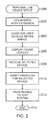
- FIGURE 2 is a flow chart illustrating procedures for setting up personal use devices 104 and 106 in accordance with one or more aspects of the present disclosure. The processes can begin at block 200. While the first personal use device 104 is setup within these procedures, those skilled in the relevant art will appreciate that the second device 106 can instead be setup first.
- a user can log into a first phone 104.
- the first phone 104 can be a user's office phone.
- an extension number can be provided with the login, which uniquely identifies the user.
- the user can choose to pair a supported Bluetooth device 110, such as a Bluetooth headset, with the phone 104.
- a supported Bluetooth device 110 such as a Bluetooth headset
- both Bluetooth-enabled mobile phones and wireless headsets are placed in pairing mode before a connection is made.
- the Bluetooth device 110o can be placed into pairing mode when turned on. On some devices 110, to conserve battery power automated pairing is shut off and must be turned on when pairing.
- the first IP phone 104 can initiate a scan of Bluetooth devices 110 within range of the phone 104. This can result in a list of potential devices 110 being presented on a display of the phone 104 at block 206. In one embodiment, the user can select their device 110 from the list. This selection can be received by the IP phone 104 at block 208. The user of the device 110 can be prompted to enter a passcode for the device.
- the passcode can be limited to numeric entries or in the alternative, alphanumeric entries.
- the phone 104 can receive the passcode for the selected device 110.
- the phone 104 becomes paired with that specific Bluetooth device 110 when the passcode is verified or authenticated at block 210.
- the IP phone 104 can pass the pairing information to the VoIP system 102, which can include the Bluetooth device UID and passcode. This can be passed to the VoIP system 102 from the IP phone 104 as part of the pairing process.
- the VoIP system 102 can store this pairing information within a user's profile against their extension number or username within the database 112.
- the processes for setting up personal use devices can end at block 214.
- FIGURE 3 is a flow chart illustrating procedures for automatically pairing personal use devices 104 and 106 in accordance with one or more aspects of the present disclosure. The processes can begin at block 300. At block 302, the user can log into an IP phone 106 connected to the VoIP system 102 using their extension number or username and a passcode.
- the IP phone 106 can retrieve the user's profile based on the extension number or username used to log in. Part of the information retrieved as part of the user's profile can be the pairing information for BluetoothTM devices 110 that the user had previously paired with the first IP phone 104.
- the Bluetooth interface within the phone 106 can scan the surrounding area to determine devices 110 that are within range at block 306.
- the IP phone 106 can compare the results of the scan with the list of previously paired devices 110 contained within their profile. This information can be pulled from the VoIP system 102 containing the system profile database 112.
- the IP Phone 106 can determine whether there is a match for the device 110. When a match is found, at block 312, the Bluetooth interface of the second IP phone 106 can automatically pair and connect the device 110 without requiring any user intervention. In this way, the device 110 can be ready to use with the IP phone 106 once the user has logged in.
- the pairing processes described in FIGURE 2 can be used to pair the device 110 with the second IP phone 106 at block 314. The processes for automatically paring with the second IP phone 106 can end at block 316.
- the pairing information local to the IP Phone 106 can be deleted while the information can remain in the centralized database 112 for the VoIP system 102.
- common use phones 120 and 122 a number of devices share a separate common pairing information database, which can be the same database 112 as used for personal use devices 104 and 106. Alternatively, an entirely separate database can be used.
- the database 112 could be searched based on the user's extension number.
- Common use devices on the other hand, can be searched based on a Bluetooth device UID. There is no need for the user to log into the conference phone 120. The conference phone 120 can check to see if any of the devices 110 in the room are contained within the pairing database 112.
- FIGURE 4 is a flow chart illustrating procedures for setting up common use devices 120 and 122 in accordance with one or more aspects of the present disclosure.
- the processes can begin at block 400.
- a Bluetooth device 110 can be paired with a first conference phone 120.
- An example of this is a VoIP conference phone 120 in a meeting room that supports connection of multiple Bluetooth devices 110 such as headsets or mobile phones or a combination thereof.
- conference phone 122 can be setup instead.
- the pairing information is stored in a database 112 that can be accessible by another conference phone 122 on the VoIP system 102.
- a user who has paired their Bluetooth device 110 with one conference phone 120 in one meeting room can walk into a different meeting room and have their Bluetooth device 110 automatically pair and connect with a second conference phone 122 in that room.
- the user can then be prompted for a username.
- the conference device 120 can receive the username associated with the Bluetooth device 110.
- the username, at block 408, can then be stored in the database 112 along with a UID of the Bluetooth device 110.
- the pairing information local to the conference device 120 can be deleted at block 410 while the information can remain in the centralized database 112 for the VoIP system 102.
- the processes can end at block 412.
- the conference phones 120 and 122 can search for the device's 110 UID within the paired device database 112 and use the information previously stored to pair the user's device 110 with the conference phones 120 and 122.
- a flow chart illustrating procedures for automatically pairing common use devices 120 and 122 in accordance with one or more aspects of the present disclosure is provided.
- the processes can begin at block 500. While conference device 122 is paired, those skilled in the relevant art will appreciate that the same processes can be used to pair conference device 120.
- the Bluetooth interface in the conference phone 122 can periodically scan for Bluetooth devices 110 within range. In order to avoid picking up transient devices 110, the Bluetooth interface in the conference phone 122 can conclude that a device 110 is present when the device 110 remains within range for a predetermined number of scan periods. This is typically required in the case of common use devices 120 and 122, such as a conference phone, because the conference phone automatically pairs without any user intervention. In the case of the personal use device, the user must generally log into the device first, while for common use devices, users are automatically connected. In one embodiment, a device 110 is present when three scans are made and each of the scans found the device 110.
- the conference phone 122 can determine whether the predetermined number of scans has been detected and whether any Bluetooth devices 110 have been found. When no devices 110 have been found, the conference phone 122 can continue to scan. This can show that there is no definitive conclusion that the device 110 is within range and should be paired. Because the previous pairing information was deleted from conference phone 120, the processes described herein can be used to reestablish the connection with the Bluetooth device 110 and the conference phone 120.
- the Bluetooth interface in the conference phone 122 can search the central paired device database 112 at block 506.
- the conference phone 122 can determine if the pairing information for the device 110 has been stored. When it has, the conference phone 122 can retrieve the pairing information for the device 110 from the database 112 at block 510. The user device 110 can then be paired and connected with the conference phone 122 automatically using the retrieved information at block 512. Otherwise, and when the pairing information is not found, the device 110 can be paired through pairing processes described in FIGURE 4 at block 514. In one embodiment, the device 110 can be disconnected with the first conference phone 120 before automatically connecting to the second conference phone 122.
- the conference phone 122 can display a list of Bluetooth devices 110 that have been paired and connected. Generally, this is only applicable to common use devices 120 and 122 where any number of devices 110 can be paired. The user of the conference phone 122 can see whose devices 110 are paired in order to identify if there are any paired devices 110for users that are not in the room. For example, a user can be close enough to the meeting room such that their device 110 is considered present even though they are not physically in the room. The user of the conference phone 122 can then choose to disconnect or un-pair any devices 110 that are not actually present in the room at block 518. This removes them locally, but does not remove them from the central database 112. The processes for automatically pairing common use devices 120 and 122 can end at block 520.
- computer software and/or data is stored on a machine readable medium as part of a computer program product, and is loaded into a computer system or other device or machine via a removable storage drive, hard drive, or communications interface.
- Computer programs, also called computer control logic or computer readable program code are stored in a main and/or secondary memory, and executed by one or more processors, controllers, or the like to cause the one or more processors to perform the functions of the disclosure as described herein.
- One aspect of the specification provides a system comprising:
- Said wireless device may be disconnected with said first common use device or said second common use device when out of range.
- the system may comprise a terminal for an administrator who turns on or off automatic connections.
- Another aspect provides a conference apparatus configured to:
- the conference apparatus may comprise a display, wherein said memory storing program instructions, when executed by said processor, causes said processor to provide a list of all user devices found within said range of said conference apparatus to said display.
- the conference apparatus may disconnect paired devices when instructed.
- Said predetermined number of scan may be three.
Landscapes
- Engineering & Computer Science (AREA)
- Computer Networks & Wireless Communication (AREA)
- Human Computer Interaction (AREA)
- Signal Processing (AREA)
- Telephonic Communication Services (AREA)
- Mobile Radio Communication Systems (AREA)
Abstract
Description
- This disclosure generally relates to pairing, and more particularly, to connecting a Bluetooth™ device that has been paired with one communication device automatically to another communication device on the same system.
- With the popularity of Bluetooth™ wireless interfaces, it is becoming more common for Internet Protocol (IP) phone manufacturers to offer Bluetooth™ interfaces within their phones to enable connection of devices such as headsets, keyboards, mice and mobile handsets. Operationally, in order to use their Bluetooth™ device with an IP phone, the user must first pair the device with the phone. The user can then choose to have the device connect to the phone whenever they are within range so the device can be used. For example, if the user pairs their Bluetooth headset with their IP phone, whenever they are within range of their IP phone, they can use the headset for calls placed or received on the IP phone.
- Most Voice over Internet Protocol (VoIP) system vendors provide the ability for a user to log into any IP phone in the system and make it their own such that the phone assumes their programmed speed dials, privileges and other phone settings. Nevertheless, with each different phone the user logs into, they are required to go through the process of pairing their Bluetooth™ device to the IP phone. Accessing the pairing process in many phones is not obvious to the user and in general, results in a hassle for the user diminishing the value of being able to use their Bluetooth™ device with the IP phone currently being used.
- Many of the services offered over Bluetooth can expose private data or allow a party to eavesdrop using their Bluetooth device. For security reasons it is therefore necessary to control which Bluetooth devices are allowed to connect to a given device. At the same time, it is useful for Bluetooth devices to automatically establish a connection without user intervention as soon as they are in range.
- A Bluetooth device and system aimed at eliminating the need to pair a user's Bluetooth device as they move from one IP phone to another is therefore needed. These, as well as other related advantages and features, will be described in the present disclosure.
- The novel features believed to be characteristic of the disclosure are set forth in the appended claims. In the descriptions that follow, like parts are marked throughout the specification and drawings with the same numerals, respectively. The drawing figures are not necessarily drawn to scale and certain figures can be shown in exaggerated or generalized form in the interest of clarity and conciseness. The disclosure itself, however, as well as a preferred mode of use, further objectives and advantages thereof, will be best understood by reference to the following detailed description of illustrative embodiments when read in conjunction with the accompanying drawings, wherein:
-
FIGURE 1 is an exemplary system depicting centralized Bluetooth™ device pairing in accordance with one or more aspects of the present disclosure; -
FIGURE 2 is a flow chart illustrating procedures for setting up personal use devices in accordance with one or more aspects of the present disclosure; -
FIGURE 3 is a flow chart illustrating procedures for automatically pairing personal use devices in accordance with one or more aspects of the present disclosure; -
FIGURE 4 is a flow chart illustrating procedures for setting up common use devices in accordance with one or more aspects of the present disclosure; and -
FIGURE 5 is a flow chart illustrating procedures for automatically pairing common use devices in accordance with one or more aspects of the present disclosure. - The description set forth below in connection with the appended drawings is intended as a description of presently preferred embodiments of the disclosure and is not intended to represent the only forms in which the present disclosure can be constructed and/or utilized. The description sets forth the functions and the sequence of steps for constructing and operating the disclosure in connection with the illustrated embodiments. It is to be understood, however, that the same or equivalent functions and sequences can be accomplished by different embodiments that are also intended to be encompassed within the spirit and scope of this disclosure.
- The present disclosure relates to pairing devices. More particularly, this disclosure relates to centralized Bluetooth™ pairing. In one illustrative embodiment, the centralized pairing provides the ability to have a Bluetooth device that has been paired to one Internet Protocol (IP) phone on a Voice over Internet Protocol (VoIP) system automatically pair to another IP phone on the same system when the user logs in to that phone. This pairing, intended for a personal use device, can be tied to a user profile and be initiated once the user logs into the other IP phone. In another illustrative embodiment, that can be related or not, centralized pairing can be provided which can allow a Bluetooth device that has been paired to an IP conference phone in one meeting room to automatically pair to another IP conference phone in a different meeting room when they enter that room. To prevent erroneous pairings caused by transient devices, the Bluetooth interface in the conference phones can periodically scan for Bluetooth devices within range and pair the device if it is still within range after a predetermined number of scans. This pairing for common use devices is generally not tied to a user profile and is automatic without user login. In both illustrative embodiments, the pairings can co-exist in an enterprise and can potentially share a common paired device database by searching the data in different manners i.e. search for a user profile versus search for a device unique identifier (UID).
- Numerous advantages can be offered by the illustrative embodiment described above. A centralized mechanism for storing pairing information for a user's Bluetooth device against their VoIP system profile can allow a user to log into a VoIP phone, upload the user's device pairing information into the VoIP phone from the centralized VoIP system and automatically pair the device if it is within range once the user is logged into the phone thereby removing security deficiencies. Once logged in and paired with one device, the user no longer has to pair with other devices creating additional benefits. Many additional advantages of the present disclosure will become apparent to those skilled in the relevant art as provided for in the following description.
- An exemplary environment for pairing a Bluetooth device with multiple communication devices will be described in
FIGURE 1 .FIGURES 2 through 5 will provide exemplary procedures for pairing these devices. Bluetooth is a short-range, wireless technology developed to help eliminate the use of physical cables for both portable and fixed-location devices. While Bluetooth has been primarily used in the present disclosure, those skilled in the relevant art will appreciate that other standards for wireless communications can be implemented including technologies that are capable of identifying a device's location such as WiFi™, Global System for Mobile Communications (GSM™), Global Positioning Systems (GPS), etc. The centralized VoIP system can be referred to as a centralized system. IP phones, for purposes of the present disclosure, can be interchangeable with other communication devices. These IP phones can also be referred to as personal use devices. Conference phones, as described herein, can also be interchangeable with other communication devices and can be referred to as common use devices. - Turning now to
FIGURE 1 , anexemplary system 100 depicting centralized Bluetooth device pairing in accordance with one or more aspects of the present disclosure is provided. Thesystem 100 can include acentralized VoIP system 102 that can be coupled to a number of different components including, but not limited to, afirst IP phone 104 and asecond IP phone 106 or afirst conference phone 120 and asecond conference phone 120. Asystem administrator terminal 108 can also be connected to theVoIP system 102. Thephones Bluetooth device 110. Aseparate database 112 for storing system profiles associated with paireddevices 110 can be maintained. Thesystem 100 shown represents one embodiment and should not be construed as the only working environment for thecentralized system 102 and thephones system 100 can be separated into two systems, one representing Bluetooth pairing with thepersonal use devices common use devices - The
VoIP system 102 can operate on a traditional server. The server can include an operating system and software instructions, ROM, RAM, at least one processor and a network interface. Thedatabase 112 storing system profiles can be a part of or connected to theVoIP system 102. The server can process requests fromphones system 100. The server can typically handle high volumes of transactions and large amount of queries for communication and data processing. RAM and ROM are used to support the program codes that are operated by the processor. The memory can be in a form of a hard disk, CD ROM, or equivalent storage medium. The processor can support the authentications such as communications from external data servers, as well as allowing for anonymous transactions and general data encryption. - The data storage on the server for the
VoIP system 102 can include hard disk magnetic or optical storage units, as well as CD ROM, CD RW or DVD ROM and flash memory such as compact flash and secure digital cards. The data storage contains databases used in the processing of transactions. Conventional Ethernet technology can serve as the network interface. Alternatively a cable or DSL modem can be used as a network interface. While the above embodiment describes a single component acting as the server for theVoIP system 102, the functionality can be distributed over multiple computing systems. In one embodiment, the server is configured in a distributed architecture, wherein the databases and processors are housed in separate units or locations. - With reference to the
phones VoIP system 102. Thephones phones system 100. - An
administrator terminal 108 can be coupled to theVoIP system 102. Through the terminal 108, an interface for system administrators can be provided for the paireddevice database 112. In one embodiment, the terminal 108 for system administrators can allow them to delete auser device 110 record or turn off the auto-connect capability for a particular user, for example, to prevent auto-pairing of adevice 110 that belongs to a user who sits close to a meeting room resulting in theirdevice 110 auto-pairing to thephones - Continuing with
FIGURE 1 ,Bluetooth devices 110 can be connected wirelessly with thephones 104, 106,120 and 122. Thephones devices 110. TheBluetooth devices 110 can be, but are not limited to, headsets, keyboards, mice and mobile handsets. Components within thesystem 100 can be connected to other components through a network. Those skilled in the relevant art will appreciate that the network can include the Internet, intranet, wide-area network (WAN), local-area network (LAN), personal-area network (PAN), campus-area network (CAN), metropolitan area network (MAN), global-area network (GAN), virtual private network, or any other type of network supporting communication between components of thesystem 100. Both wired and wireless connections, including optical links, can be implemented. - The technology described herein can be implemented as logical operations and/or modules. The logical operations can be implemented as a sequence of processor-implemented steps executing in one or more computer systems and as interconnected machine or circuit modules within one or more computer systems. Likewise, the descriptions of various component modules can be provided in terms of operations executed or effected by the modules. The resulting implementation is a matter of choice, dependent on the performance requirements of the underlying environment in which the described disclosure is implemented. The logical operations making up the embodiment of the disclosure described herein are referred to variously as operations, steps, objects, or modules. It should be understood that logical operations can be performed in any order, unless explicitly claimed otherwise or a specific order is inherently necessitated by the claim language.
- Various embodiments of the present disclosure can be programmed using an object-oriented programming language, such as SmallTalk, Java, C++, Ada, or C#. Other object-oriented programming languages can also be used.
- Alternatively, functional, scripting, and/or logical programming languages can be used. Various aspects of this disclosure can be implemented in a non-programmed environment, for example, documents created in HTML, XML, or other format that, when viewed in a window of a browser program, render aspects of a GUI or perform other functions. Various aspects of the disclosure can be implemented as programmed or non-programmed elements, or any combination thereof.
- As depicted above, the
VoIP system 102 was used for automatically connecting auser device 110 withpersonal use devices common use devices personal use devices first phone 104 in order to pair theirdevice 110 and has their pairing information uploaded into thecentral VoIP system 102.FIGURE 2 is a flow chart illustrating procedures for setting uppersonal use devices block 200. While the firstpersonal use device 104 is setup within these procedures, those skilled in the relevant art will appreciate that thesecond device 106 can instead be setup first. - At
block 202, a user can log into afirst phone 104. In one embodiment, thefirst phone 104 can be a user's office phone. Typically, an extension number can be provided with the login, which uniquely identifies the user. After logging in, the user can choose to pair a supportedBluetooth device 110, such as a Bluetooth headset, with thephone 104. To begin the pairing processes, generally, both Bluetooth-enabled mobile phones and wireless headsets are placed in pairing mode before a connection is made. In one embodiment, the Bluetooth device 110o can be placed into pairing mode when turned on. On somedevices 110, to conserve battery power automated pairing is shut off and must be turned on when pairing. - At
block 204, thefirst IP phone 104 can initiate a scan ofBluetooth devices 110 within range of thephone 104. This can result in a list ofpotential devices 110 being presented on a display of thephone 104 atblock 206. In one embodiment, the user can select theirdevice 110 from the list. This selection can be received by theIP phone 104 atblock 208. The user of thedevice 110 can be prompted to enter a passcode for the device. The passcode can be limited to numeric entries or in the alternative, alphanumeric entries. - The
phone 104 can receive the passcode for the selecteddevice 110. Thephone 104 becomes paired with thatspecific Bluetooth device 110 when the passcode is verified or authenticated atblock 210. Atblock 212, theIP phone 104 can pass the pairing information to theVoIP system 102, which can include the Bluetooth device UID and passcode. This can be passed to theVoIP system 102 from theIP phone 104 as part of the pairing process. TheVoIP system 102 can store this pairing information within a user's profile against their extension number or username within thedatabase 112. The processes for setting up personal use devices can end atblock 214. - After pairing with the
first phone 104, theuser device 110 can be automatically paired when the user logs into anotherphone 106 by tying the user profile that was earlier stored in thedatabase 112.FIGURE 3 is a flow chart illustrating procedures for automatically pairingpersonal use devices block 300. Atblock 302, the user can log into anIP phone 106 connected to theVoIP system 102 using their extension number or username and a passcode. - At
block 304, theIP phone 106 can retrieve the user's profile based on the extension number or username used to log in. Part of the information retrieved as part of the user's profile can be the pairing information forBluetooth™ devices 110 that the user had previously paired with thefirst IP phone 104. The Bluetooth interface within thephone 106 can scan the surrounding area to determinedevices 110 that are within range atblock 306. - At
block 308, theIP phone 106 can compare the results of the scan with the list of previously paireddevices 110 contained within their profile. This information can be pulled from theVoIP system 102 containing thesystem profile database 112. Atdecision block 310, theIP Phone 106 can determine whether there is a match for thedevice 110. When a match is found, atblock 312, the Bluetooth interface of thesecond IP phone 106 can automatically pair and connect thedevice 110 without requiring any user intervention. In this way, thedevice 110 can be ready to use with theIP phone 106 once the user has logged in. Alternatively, the pairing processes described inFIGURE 2 can be used to pair thedevice 110 with thesecond IP phone 106 atblock 314. The processes for automatically paring with thesecond IP phone 106 can end atblock 316. When the user logs out of the personaluse IP Phone 106, the pairing information local to theIP Phone 106 can be deleted while the information can remain in thecentralized database 112 for theVoIP system 102. - With
common use phones same database 112 as used forpersonal use devices personal use devices database 112 could be searched based on the user's extension number. Common use devices, on the other hand, can be searched based on a Bluetooth device UID. There is no need for the user to log into theconference phone 120. Theconference phone 120 can check to see if any of thedevices 110 in the room are contained within thepairing database 112. -
FIGURE 4 is a flow chart illustrating procedures for setting upcommon use devices block 400. Atblock 402, aBluetooth device 110 can be paired with afirst conference phone 120. An example of this is aVoIP conference phone 120 in a meeting room that supports connection ofmultiple Bluetooth devices 110 such as headsets or mobile phones or a combination thereof. Those skilled in the relevant art will appreciate thatconference phone 122 can be setup instead. - At
block 404, the pairing information is stored in adatabase 112 that can be accessible by anotherconference phone 122 on theVoIP system 102. In this way, a user who has paired theirBluetooth device 110 with oneconference phone 120 in one meeting room can walk into a different meeting room and have theirBluetooth device 110 automatically pair and connect with asecond conference phone 122 in that room. The user can then be prompted for a username. Atblock 406, theconference device 120 can receive the username associated with theBluetooth device 110. The username, atblock 408, can then be stored in thedatabase 112 along with a UID of theBluetooth device 110. When theBluetooth device 110 is no longer required or is out of range of theconference device 120, the pairing information local to theconference device 120 can be deleted atblock 410 while the information can remain in thecentralized database 112 for theVoIP system 102. The processes can end atblock 412. - As described above, the first time a user pairs their
Bluetooth device 110 with theconference phone 120 on thesystem 102, their pairing information is stored both in the conference phone's local Bluetooth interface and also in a paireddevice database 112 stored in acentralized VoIP system 102 that is accessible by other phones. Alternatively, if the user has already paired theirdevice 110 with their personaluse IP Phone 104, theconference phones device database 112 and use the information previously stored to pair the user'sdevice 110 with theconference phones - Referring to
FIGURE 5 , a flow chart illustrating procedures for automatically pairingcommon use devices block 500. Whileconference device 122 is paired, those skilled in the relevant art will appreciate that the same processes can be used to pairconference device 120. Atblock 502, the Bluetooth interface in theconference phone 122 can periodically scan forBluetooth devices 110 within range. In order to avoid picking uptransient devices 110, the Bluetooth interface in theconference phone 122 can conclude that adevice 110 is present when thedevice 110 remains within range for a predetermined number of scan periods. This is typically required in the case ofcommon use devices device 110 is present when three scans are made and each of the scans found thedevice 110. - At
decision block 504, theconference phone 122 can determine whether the predetermined number of scans has been detected and whether anyBluetooth devices 110 have been found. When nodevices 110 have been found, theconference phone 122 can continue to scan. This can show that there is no definitive conclusion that thedevice 110 is within range and should be paired. Because the previous pairing information was deleted fromconference phone 120, the processes described herein can be used to reestablish the connection with theBluetooth device 110 and theconference phone 120. - Once the Bluetooth interface in the
conference phone 122 has determined that adevice 110 is present, it can search the central paireddevice database 112 atblock 506. Atdecision block 508, theconference phone 122 can determine if the pairing information for thedevice 110 has been stored. When it has, theconference phone 122 can retrieve the pairing information for thedevice 110 from thedatabase 112 atblock 510. Theuser device 110 can then be paired and connected with theconference phone 122 automatically using the retrieved information atblock 512. Otherwise, and when the pairing information is not found, thedevice 110 can be paired through pairing processes described inFIGURE 4 atblock 514. In one embodiment, thedevice 110 can be disconnected with thefirst conference phone 120 before automatically connecting to thesecond conference phone 122. - At
block 516, theconference phone 122 can display a list ofBluetooth devices 110 that have been paired and connected. Generally, this is only applicable tocommon use devices devices 110 can be paired. The user of theconference phone 122 can see whosedevices 110 are paired in order to identify if there are any paired devices 110for users that are not in the room. For example, a user can be close enough to the meeting room such that theirdevice 110 is considered present even though they are not physically in the room. The user of theconference phone 122 can then choose to disconnect or un-pair anydevices 110 that are not actually present in the room atblock 518. This removes them locally, but does not remove them from thecentral database 112. The processes for automatically pairingcommon use devices block 520. - In software implementations, computer software and/or data is stored on a machine readable medium as part of a computer program product, and is loaded into a computer system or other device or machine via a removable storage drive, hard drive, or communications interface. Computer programs, also called computer control logic or computer readable program code, are stored in a main and/or secondary memory, and executed by one or more processors, controllers, or the like to cause the one or more processors to perform the functions of the disclosure as described herein.
- The figures and examples above are not meant to limit the scope of the present disclosure to a single embodiment, as other embodiments are possible by way of interchange of some or all of the described or illustrated elements. Moreover, where certain elements of the present disclosure can be partially or fully implemented using known components, only those portions of such known components that are necessary for an understanding of the present disclosure are described, and detailed descriptions of other portions of such known components are omitted so as not to obscure the disclosure. In the present disclosure, an embodiment showing a singular component should not necessarily be limited to other embodiments including a plurality of the same component, and vice-versa, unless explicitly stated otherwise herein. Moreover, applicants do not intend for any term in the specification or claims to be ascribed an uncommon or special meaning unless explicitly set forth as such. Further, the present disclosure encompasses present and future known equivalents to the known components referred to herein by way of illustration.
- The foregoing description is provided to enable any person skilled in the relevant art to practice the various embodiments described herein. Various modifications to these embodiments will be readily apparent to those skilled in the relevant art, and generic principles defined herein can be applied to other embodiments. Thus, the claims are not intended to be limited to the embodiments shown and described herein, but are to be accorded the full scope consistent with the language of the claims, wherein reference to an element in the singular is not intended to mean "one and only one" unless specifically stated, but rather "one or more." All structural and functional equivalents to the elements of the various embodiments described throughout this disclosure that are known or later come to be known to those of ordinary skill in the relevant art are expressly incorporated herein by reference and intended to be encompassed by the claims. Moreover, nothing disclosed herein is intended to be dedicated to the public regardless of whether such disclosure is explicitly recited in the claims.
- One aspect of the specification provides a system comprising:
- a database coupled to a plurality of common use devices;
- Said wireless device may be disconnected with said first common use device or said second common use device when out of range.
- The system may comprise a terminal for an administrator who turns on or off automatic connections.
- Another aspect provides a conference apparatus configured to:
- scan for at least one user wireless device;
- search for a unique identifier (UID) associated with said at least one user wireless device when said at least one user wireless device is within range of said conference apparatus for a predetermined number of scans;
- pair said at least one user wireless device when said UID is found for said at least one user wireless device.
- The conference apparatus may comprise a display, wherein said memory storing program instructions, when executed by said processor, causes said processor to provide a list of all user devices found within said range of said conference apparatus to said display.
- The conference apparatus may disconnect paired devices when instructed. Said predetermined number of scan may be three.
Claims (15)
- A method of connecting a user wireless device with a plurality of personal use devices, said method comprising:pairing a user wireless device with a personal use device;storing pairing information against a user profile; andpairing said user wireless device with at least one other personal use device through said pairing information stored against said user profile.
- The method of claim 1, wherein pairing said user wireless device with said personal use device comprises:logging into said personal use device by entering an extension number or username and passcode;initiating a pairing process on said personal use device and said user wireless device;selecting said wireless device from a list of wireless devices within range displayed on said personal use device; andentering a passcode for said wireless device on said personal use device.
- The method of claim 2, wherein storing said pairing information against said user profile comprises placing a unique identifier (UID) and said passcode for said wireless device into a database.
- The method of claim 3, wherein pairing said user wireless device with at least one other personal use device through said pairing information stored against said user profile comprises:logging into said at least one other personal use device through said extension number or username and passcode;locating said user profile through said extension number or username; andconnecting said user wireless device with said at least one other personal use device when said UID and passcode for said user wireless device are found in said pairing information stored against said user profile.
- The method of any preceding claim, wherein storing said pairing information against a user profile comprises providing said pairing information to a centralized Voice over Internet Protocol system that maintains a plurality of user profiles.
- The method of any preceding claim, comprising removing said pairing between said user wireless device and said personal use device.
- The method of any preceding claim, wherein said personal use devices are IP phones.
- A system comprising:a database coupled to a plurality of common use devices;wherein a unique identifier (UID) is captured when a user of a wireless device pairs and connects with a first common use device, said UID of said wireless device stored in said database by said first common use device, said user of said wireless device automatically connecting to a second common use device when said wireless device comes within range of said second common use device and said UID is retrieved from said wireless device and associated with said UID in said database stored by said first common use device.
- The system of claim 8, wherein said plurality of common use devices are conference phones.
- The system of claim 8 or claim 9, wherein said database comprises a list of previously connected wireless devices for said user.
- The system of any of claims 8 to 10, wherein said wireless device is disconnected with said first common use device before automatically connecting to said second common use device.
- A conference apparatus configured to:scan for at least one user wireless device;search for a unique identifier (UID) associated with said at least one user wireless device when said at least one user wireless device is within range of said conference apparatus for a predetermined number of scans;pair said at least one user wireless device when said UID is found for said at least one user wireless device.
- The conference apparatus of claim 12, configured to provide setup processes to initially pair said at least one user device.
- The conference apparatus of claim 12 or claim 13, wherein scanning for said at least one user device comprises searching through a plurality of user devices on a Bluetooth interface.
- The conference apparatus of any of claims 12 to 14 , wherein searching for said UID comprises accessing a remote database connected to a plurality of conference apparatuses.
Applications Claiming Priority (1)
| Application Number | Priority Date | Filing Date | Title |
|---|---|---|---|
| US13/134,707 US20120322376A1 (en) | 2011-06-14 | 2011-06-14 | Centralized Bluetooth device pairing |
Publications (2)
| Publication Number | Publication Date |
|---|---|
| EP2536185A2 true EP2536185A2 (en) | 2012-12-19 |
| EP2536185A3 EP2536185A3 (en) | 2012-12-26 |
Family
ID=46229336
Family Applications (1)
| Application Number | Title | Priority Date | Filing Date |
|---|---|---|---|
| EP12171519A Withdrawn EP2536185A3 (en) | 2011-06-14 | 2012-06-11 | Centralized Bluetooth Device Pairing |
Country Status (4)
| Country | Link |
|---|---|
| US (1) | US20120322376A1 (en) |
| EP (1) | EP2536185A3 (en) |
| CN (1) | CN102917113A (en) |
| CA (1) | CA2778564A1 (en) |
Cited By (4)
| Publication number | Priority date | Publication date | Assignee | Title |
|---|---|---|---|---|
| US9445032B2 (en) | 2014-03-24 | 2016-09-13 | Broadcom Corporation | Auto-pairing control device |
| US9668291B2 (en) | 2015-07-13 | 2017-05-30 | BeneGear Inc. | Pairing method of gym system |
| GB2558406A (en) * | 2016-11-15 | 2018-07-11 | I6 Group Ltd | Pairing arrangement and method |
| US12634684B2 (en) | 2022-08-24 | 2026-05-19 | Omron Healthcare Co., Ltd. | Measurement device |
Families Citing this family (38)
| Publication number | Priority date | Publication date | Assignee | Title |
|---|---|---|---|---|
| US8775533B2 (en) * | 2011-05-20 | 2014-07-08 | Microsoft Corporation | Auto connect in peer-to-peer network |
| US10225354B2 (en) * | 2011-06-06 | 2019-03-05 | Mitel Networks Corporation | Proximity session mobility |
| US20130115880A1 (en) * | 2011-11-09 | 2013-05-09 | Cisco Technology, Inc. | Pairing a Bluetooth Device to a Virtual Desktop in a Hosted Desktop Environment |
| US20130265857A1 (en) * | 2011-11-10 | 2013-10-10 | Microsoft Corporation | Device Association |
| US9628514B2 (en) | 2011-11-10 | 2017-04-18 | Skype | Device association using an audio signal |
| US9450930B2 (en) | 2011-11-10 | 2016-09-20 | Microsoft Technology Licensing, Llc | Device association via video handshake |
| US9258704B2 (en) * | 2012-06-27 | 2016-02-09 | Advanced Messaging Technologies, Inc. | Facilitating network login |
| CN103518418B (en) * | 2012-09-27 | 2019-07-26 | 华为终端有限公司 | Method and device for connection between bluetooth devices |
| US9929876B2 (en) * | 2013-03-15 | 2018-03-27 | Kortek Industries Pty Ltd | Adaptable multi-mode wireless power, light and automation |
| KR102138034B1 (en) * | 2013-10-08 | 2020-07-27 | 삼성전자 주식회사 | Mobile terminal and auxiliary device for mobile terminal and method for controlling the same |
| US10331098B2 (en) * | 2013-12-03 | 2019-06-25 | Guangzhou Kugou Computer Technology Co., Ltd. | Playback control method, player device, and storage medium |
| CN104091606B (en) * | 2013-12-03 | 2016-06-01 | 腾讯科技(深圳)有限公司 | A kind of control method for playing back, and device |
| US9621645B2 (en) | 2013-12-30 | 2017-04-11 | Google Inc. | Device pairing via a cloud server |
| US9516024B2 (en) | 2014-04-17 | 2016-12-06 | Honda Motor Co., Ltd. | Connection authentication |
| CN103997712B (en) * | 2014-04-30 | 2017-11-17 | 宇龙计算机通信科技(深圳)有限公司 | The method and mobile terminal that prompting user is traced |
| US10235512B2 (en) * | 2014-06-24 | 2019-03-19 | Paypal, Inc. | Systems and methods for authentication via bluetooth device |
| US20160227097A1 (en) | 2015-02-04 | 2016-08-04 | Casio Computer Co., Ltd. | Data processing device that executes predetermined data processing by linking with other apparatus |
| US9585015B2 (en) * | 2015-04-21 | 2017-02-28 | Motorola Solutions, Inc | Method and apparatus for authentication of collaborative mobile devices |
| US9913079B2 (en) | 2015-06-05 | 2018-03-06 | Apple Inc. | Cloud-based proximity pairing and switching for peer-to-peer devices |
| US10261568B2 (en) | 2015-09-16 | 2019-04-16 | Microsoft Technology Licensing, Llc | Enhancing user experience relative to peripheral devices |
| US9912668B2 (en) * | 2015-09-16 | 2018-03-06 | Microsoft Technology Licensing, Llc | Enhancing user experience relative to peripheral devices |
| CN105611488A (en) * | 2015-12-31 | 2016-05-25 | 福建联迪商用设备有限公司 | Automatic Bluetooth connection method and master device, slave device and system |
| EP3414868B1 (en) | 2016-03-30 | 2021-12-08 | Hewlett-Packard Development Company, L.P. | Meeting passcodes |
| EP3244645B1 (en) | 2016-05-09 | 2021-09-15 | ABB Schweiz AG | Pairing procedure |
| US11197331B2 (en) | 2016-06-10 | 2021-12-07 | Apple Inc. | Zero-round-trip-time connectivity over the wider area network |
| US10713204B2 (en) | 2016-07-28 | 2020-07-14 | Hewlett-Packard Development Company, L.P. | Controlling a mode of communication between a host computer and a detachable peripheral device |
| CN106502113B (en) * | 2016-11-09 | 2020-05-29 | 中磊电子(苏州)有限公司 | Automatic pairing method and server |
| US11470199B2 (en) * | 2017-02-24 | 2022-10-11 | Avaya Inc. | System and method for personalizing a shared conferencing device or a shared printer/scanner |
| US10506069B2 (en) | 2017-08-08 | 2019-12-10 | Microsoft Technology Licensing, Llc | Virtual profile for Bluetooth |
| CN108200561A (en) * | 2017-12-29 | 2018-06-22 | 江苏惠通集团有限责任公司 | Unpaired message management method, node management device, control device and server |
| EP3759957A4 (en) * | 2018-03-02 | 2022-02-09 | Nitto Denko Corporation | DEVICE PAIRING SYSTEM AND METHOD AND DEVICE COMMUNICATION CONTROL SYSTEM AND METHOD |
| WO2020227282A1 (en) * | 2019-05-09 | 2020-11-12 | Evolution Optiks Limited | Corrective light field display profile management, communication and integration system and method |
| KR102818197B1 (en) * | 2020-07-22 | 2025-06-10 | 현대모비스 주식회사 | System and method for operating a connected device with a user terminal having heterogeneous communication modules |
| US11751033B2 (en) * | 2021-01-05 | 2023-09-05 | Plantronics, Inc. | Method for out-of-the-box pairing for unassociated wireless devices |
| WO2022177073A1 (en) | 2021-02-22 | 2022-08-25 | Lg Electronics Inc. | Display device for managing external device connected thereto through bluetooth communication and method for managing bluetooth-connected external device |
| US11856622B2 (en) | 2021-08-03 | 2023-12-26 | International Business Machines Corporation | Dynamic pairing of devices based on workflow history for wireless communication |
| FI130737B1 (en) | 2022-01-14 | 2024-02-20 | Framery Oy | DETECTOR DEFINED STATUS COMMUNICATION CONTROL |
| US20250184270A1 (en) * | 2023-12-04 | 2025-06-05 | Centurylink Intellectual Property Llc | Systems and methods for managing paired connections |
Family Cites Families (6)
| Publication number | Priority date | Publication date | Assignee | Title |
|---|---|---|---|---|
| EP1511235A1 (en) * | 2003-08-28 | 2005-03-02 | Alcatel | Distributed pairing between different terminals |
| US20070197164A1 (en) * | 2006-02-23 | 2007-08-23 | Arnold Sheynman | Method and device for automatic bluetooth pairing |
| KR20080003959A (en) * | 2006-07-04 | 2008-01-09 | 삼성전자주식회사 | Bluetooth device capable of selecting a profile and its data transmission method |
| US20080242365A1 (en) * | 2007-03-28 | 2008-10-02 | Motorola, Inc. | Devices and methods for hands-free connectivity to plural devices |
| US7912020B2 (en) * | 2007-09-21 | 2011-03-22 | Motorola Mobility, Inc. | Methods and devices for dynamic mobile conferencing with automatic pairing |
| US9363108B2 (en) * | 2008-06-05 | 2016-06-07 | Cisco Technology, Inc. | System for utilizing identity based on pairing of wireless devices |
-
2011
- 2011-06-14 US US13/134,707 patent/US20120322376A1/en not_active Abandoned
-
2012
- 2012-06-01 CA CA2778564A patent/CA2778564A1/en not_active Abandoned
- 2012-06-11 EP EP12171519A patent/EP2536185A3/en not_active Withdrawn
- 2012-06-14 CN CN2012102059617A patent/CN102917113A/en active Pending
Non-Patent Citations (1)
| Title |
|---|
| None |
Cited By (4)
| Publication number | Priority date | Publication date | Assignee | Title |
|---|---|---|---|---|
| US9445032B2 (en) | 2014-03-24 | 2016-09-13 | Broadcom Corporation | Auto-pairing control device |
| US9668291B2 (en) | 2015-07-13 | 2017-05-30 | BeneGear Inc. | Pairing method of gym system |
| GB2558406A (en) * | 2016-11-15 | 2018-07-11 | I6 Group Ltd | Pairing arrangement and method |
| US12634684B2 (en) | 2022-08-24 | 2026-05-19 | Omron Healthcare Co., Ltd. | Measurement device |
Also Published As
| Publication number | Publication date |
|---|---|
| US20120322376A1 (en) | 2012-12-20 |
| CA2778564A1 (en) | 2012-12-14 |
| CN102917113A (en) | 2013-02-06 |
| EP2536185A3 (en) | 2012-12-26 |
Similar Documents
| Publication | Publication Date | Title |
|---|---|---|
| US20120322376A1 (en) | Centralized Bluetooth device pairing | |
| US11184342B2 (en) | Multifunction wireless device | |
| US8744414B2 (en) | Methods of interacting between mobile devices and voice response systems | |
| KR101667895B1 (en) | System and method for authenticating multiple devices with a same credential | |
| CA2856882C (en) | System for transferring states between electronic devices | |
| EP2371111B1 (en) | System and method of sharing information between wireless devices | |
| US10178613B2 (en) | Wireless access method and related device and system | |
| EP2684342A1 (en) | Remote access and administration of device content and configuration using http protocol | |
| EP3169086A1 (en) | Connection method for multimedia playing device, master device, control terminal, and system | |
| US10849175B2 (en) | User-defined device connection management | |
| US20140229436A1 (en) | Method of File Synchronization and Electronic Device Thereof | |
| CN102801758A (en) | Remote system and remote operation method for terminal | |
| WO2016173348A1 (en) | Network access method and mobile communications terminal | |
| CN103944870B (en) | Communicator and its control method | |
| US20230015289A1 (en) | Web Activity Concealment | |
| WO2018103451A1 (en) | Fast wireless fidelity connection method and apparatus | |
| KR20150061563A (en) | Method and apparatus for connecting wireless lanof multi sim terminal | |
| US9843987B2 (en) | Consumer service cloud for implementing location-based services to control smart devices | |
| US8954044B1 (en) | Off-device service platform discovery | |
| US20150212967A1 (en) | Wireless Communication Adaptor And Receiver Device With Integrated Speakers | |
| JP5823185B2 (en) | Sender information providing apparatus and program | |
| US9307404B2 (en) | Mobile terminal and network unlocking method and system thereof | |
| CN114338139B (en) | Method for internet behavior management supporting terminal type control | |
| US7478123B2 (en) | Effortless registration with content providers and methods thereof | |
| WO2017004922A1 (en) | Base station locking method, mobile terminal, and computer storage medium |
Legal Events
| Date | Code | Title | Description |
|---|---|---|---|
| PUAL | Search report despatched |
Free format text: ORIGINAL CODE: 0009013 |
|
| PUAI | Public reference made under article 153(3) epc to a published international application that has entered the european phase |
Free format text: ORIGINAL CODE: 0009012 |
|
| AK | Designated contracting states |
Kind code of ref document: A2 Designated state(s): AL AT BE BG CH CY CZ DE DK EE ES FI FR GB GR HR HU IE IS IT LI LT LU LV MC MK MT NL NO PL PT RO RS SE SI SK SM TR |
|
| AX | Request for extension of the european patent |
Extension state: BA ME |
|
| AK | Designated contracting states |
Kind code of ref document: A3 Designated state(s): AL AT BE BG CH CY CZ DE DK EE ES FI FR GB GR HR HU IE IS IT LI LT LU LV MC MK MT NL NO PL PT RO RS SE SI SK SM TR |
|
| AX | Request for extension of the european patent |
Extension state: BA ME |
|
| RIC1 | Information provided on ipc code assigned before grant |
Ipc: H04W 8/26 20090101AFI20121120BHEP |
|
| 17P | Request for examination filed |
Effective date: 20130626 |
|
| RBV | Designated contracting states (corrected) |
Designated state(s): AL AT BE BG CH CY CZ DE DK EE ES FI FR GB GR HR HU IE IS IT LI LT LU LV MC MK MT NL NO PL PT RO RS SE SI SK SM TR |
|
| STAA | Information on the status of an ep patent application or granted ep patent |
Free format text: STATUS: THE APPLICATION HAS BEEN WITHDRAWN |
|
| 18W | Application withdrawn |
Effective date: 20140417 |