EP2536090A1 - Demodulation reference symbol port mapping method and apparatus - Google Patents
Demodulation reference symbol port mapping method and apparatus Download PDFInfo
- Publication number
- EP2536090A1 EP2536090A1 EP11741822A EP11741822A EP2536090A1 EP 2536090 A1 EP2536090 A1 EP 2536090A1 EP 11741822 A EP11741822 A EP 11741822A EP 11741822 A EP11741822 A EP 11741822A EP 2536090 A1 EP2536090 A1 EP 2536090A1
- Authority
- EP
- European Patent Office
- Prior art keywords
- codeword
- rank
- mapping
- reference symbol
- demodulation reference
- Prior art date
- Legal status (The legal status is an assumption and is not a legal conclusion. Google has not performed a legal analysis and makes no representation as to the accuracy of the status listed.)
- Granted
Links
Images


Classifications
-
- H—ELECTRICITY
- H04—ELECTRIC COMMUNICATION TECHNIQUE
- H04L—TRANSMISSION OF DIGITAL INFORMATION, e.g. TELEGRAPHIC COMMUNICATION
- H04L27/00—Modulated-carrier systems
- H04L27/26—Systems using multi-frequency codes
- H04L27/28—Systems using multi-frequency codes with simultaneous transmission of different frequencies each representing one code element
-
- H—ELECTRICITY
- H04—ELECTRIC COMMUNICATION TECHNIQUE
- H04L—TRANSMISSION OF DIGITAL INFORMATION, e.g. TELEGRAPHIC COMMUNICATION
- H04L5/00—Arrangements affording multiple use of the transmission path
- H04L5/003—Arrangements for allocating sub-channels of the transmission path
- H04L5/0037—Inter-user or inter-terminal allocation
-
- H—ELECTRICITY
- H04—ELECTRIC COMMUNICATION TECHNIQUE
- H04L—TRANSMISSION OF DIGITAL INFORMATION, e.g. TELEGRAPHIC COMMUNICATION
- H04L1/00—Arrangements for detecting or preventing errors in the information received
- H04L1/12—Arrangements for detecting or preventing errors in the information received by using return channel
- H04L1/16—Arrangements for detecting or preventing errors in the information received by using return channel in which the return channel carries supervisory signals, e.g. repetition request signals
- H04L1/18—Automatic repetition systems, e.g. Van Duuren systems
- H04L1/1867—Arrangements specially adapted for the transmitter end
- H04L1/1893—Physical mapping arrangements
-
- H—ELECTRICITY
- H04—ELECTRIC COMMUNICATION TECHNIQUE
- H04L—TRANSMISSION OF DIGITAL INFORMATION, e.g. TELEGRAPHIC COMMUNICATION
- H04L5/00—Arrangements affording multiple use of the transmission path
- H04L5/0001—Arrangements for dividing the transmission path
- H04L5/0026—Division using four or more dimensions, e.g. beam steering or quasi-co-location [QCL]
-
- H—ELECTRICITY
- H04—ELECTRIC COMMUNICATION TECHNIQUE
- H04L—TRANSMISSION OF DIGITAL INFORMATION, e.g. TELEGRAPHIC COMMUNICATION
- H04L5/00—Arrangements affording multiple use of the transmission path
- H04L5/003—Arrangements for allocating sub-channels of the transmission path
- H04L5/0048—Allocation of pilot signals, i.e. of signals known to the receiver
- H04L5/0051—Allocation of pilot signals, i.e. of signals known to the receiver of dedicated pilots, i.e. pilots destined for a single user or terminal
-
- H—ELECTRICITY
- H04—ELECTRIC COMMUNICATION TECHNIQUE
- H04L—TRANSMISSION OF DIGITAL INFORMATION, e.g. TELEGRAPHIC COMMUNICATION
- H04L5/00—Arrangements affording multiple use of the transmission path
- H04L5/003—Arrangements for allocating sub-channels of the transmission path
- H04L5/0058—Allocation criteria
Definitions
- the present invention relates to the field of digital communications, and more particularly, the invention relates to a method of and apparatus for mapping to a demodulation reference symbol port.
- Mobility and a broadband have become development trends of modem communication technologies, and the 3 rd Generation Partnership Project (3GPP) devotes itself to evolution of a Long Term Evolution (LTE) system as a 3G system and aims to evolve 3GPP radio access technologies toward high-data-rate, low-delay and optimized packet data applications.
- 3GPP 3 rd Generation Partnership Project
- Single User Multi-Input Multi-Output (SU-MIMO) of Long Term Evolution Advanced (LTE-A) can support parallel transmission of at most 8 data layers.
- SU-MIMO Single User Multi-Input Multi-Output
- DMRS Demodulation Reference Symbol
- an evolved NodeB eNB
- eNB evolved NodeB
- eNB evolved NodeB
- eNB evolved NodeB
- a layer a layer
- 8-port DMRS will be defined in the LTE-A.
- the DMRS is processed with the same pre-coding as data, and the UE can know an equivalent channel matrix after pre-coding and demodulate the data by measuring the DMRS.
- the downlink SU-MIMO of the LTE-A can support at most 8 layers, each of which corresponds to a DMRS port.
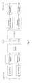
- a process flow of a downlink physical channel is as illustrated in Fig. 1 .
- downlink data transmission of each UE can support at most 2 codewords, each of which corresponds to a Transport Block (TB), and a Modulation and Coding Scheme (MCS) of each codword can be controlled by an eNB dependent upon a link condition.
- the eNB will further determine the number of data streams to be used for parallel transmission dependent upon a spatial characteristic of a channel, a service type, a priority, the amount of traffic and other factors. Transmission of at most 8 layers can be supported in the LTE-A.
- a codeword-to-layer mapping relationship is defined by a layer mapper module, and at present an agreement has been reached upon definition of layer mapper function in spatially multiplexed transmission, where specific layer mapper functions are as depicted in Table 1 and Table 2.
- a pre-coding module performs pre-coding based upon a Pre-coding Matrix Indicator (PMI).
- PMI Pre-coding Matrix Indicator
- the pre-coding module functions to map respective data layers to DMRS ports.
- layer-to-port mapping is just simple one-to-one mapping because there is only one dedicated pilot, the port 5.
- two dedicated pilots, the port 7 and the port 8 are defined, and a layer-to-port mapping scheme is defined as
- DRMS patterns at the ranks 5-8 are under ongoing discussion, but substantially it can be determined that in the DMRS patterns at the ranks 5-8, respective DMRS ports will be multiplexed in a Code Division Multiplexing-Frequency Division Multiplexing scheme.
- the layer-to-port mapping relationship in the LTE-A is relatively complex in that both a scheme of allocating layers corresponding to respective codewords across respective CDM groups and a relationship between a DMRS pattern and a rate matching module during retransmission have to be taken into account.
- the method illustrated in Fig.3 can be adopted at present for the issue of layer-to-port mapping in the LTE-A. Under a mapping principle thereof, layers corresponding to different codewords have to be mapped into different CDM groups.
- an aspect of embodiments of the invention discloses a method of mapping to a demodulation reference symbol port, which includes the steps of:
- a base station assigning a User Equipment, UE, with a corresponding data stream dependent upon an attribute of the UE; the base station mapping the corresponding data stream from a layer to a corresponding demodulation reference symbol port; and the base station transmitting the corresponding data stream to the UE via the demodulation reference symbol port.
- UE User Equipment
- Another aspect of the embodiments of the invention further discloses a base station including a transceiver module and a mapping module, wherein:
- the transceiver module is configured to assign a User Equipment, UE, with a corresponding data stream dependent upon an attribute of the UE; the mapping module is configured to map the corresponding data stream from a layer to a corresponding demodulation reference symbol port; and the transceiver module is further configured to transmit the corresponding data stream to the UE via the demodulation reference symbol port.
- UE User Equipment
- Fig.1 is a process flow chart of a downlink physical channel in the prior art
- Fig.3 is a schematic diagram of a layer-to-DMRS port mapping relationship in the prior art
- Fig.4 is a flow chart of a method of mapping to a DMRS port according to an embodiment of the invention.
- Fig. 13 is a schematic structural diagram of a base station according to an embodiment of the invention.
- an embodiment of the invention discloses a method of mapping to a demodulation reference symbol port, which includes the following steps:
- a base station assigns a UE with a corresponding data stream dependent upon an attribute of the UE; the base station maps the corresponding data stream from a layer to a corresponding demodulation reference symbol port; and the base station transmits the corresponding data stream to the UE via the demodulation reference symbol port.
- Fig.4 is a flow chart of a method of mapping to a DMRS port according to an embodiment of the invention, which includes the following steps:
- a base station determines an attribute of a UE and assigns the UE with a corresponding data stream.
- the base station communicates with the UE and assigns the UE with a corresponding data stream dependent upon an attribute of the UE.
- the eNB assigns each scheduled UE with a specific number of parallel data streams dependent upon a channel condition, a service characteristic, a priority and other factors of each UE, where each data stream is referred to as a layer.
- an 8-port DMRS will be defined in the LTE-A.
- the MMRS is processed with the same pre-coding as data, and the UE can know an equivalent channel matrix after pre-coding and demodulate the data by measuring the DMRS.
- the downlink SU-MIMO of the LTE-A can support at most 8 layers, each of which corresponds to a DMRS port.
- a process flow of a downlink physical channel is as illustrated in Fig. 1 .
- the base station maps the corresponding data stream from a layer to a corresponding demodulation reference symbol port.
- the base station transmits data to the UE via the demodulation reference symbol port.
- the base station maps the corresponding data stream from a layer to a corresponding demodulation reference symbol port.
- the base station mapping the corresponding data stream from a layer to a corresponding demodulation reference symbol port includes:
- the corresponding data stream can be mapped onto any port and occupy any CDM group.
- MU-MIMO assumed Multi-User Multi-Input Multi-Output
- a data layer can be mapped onto any port in ⁇ 0,...,M ⁇ and occupy any CDM group regardless of retransmission or initial transmission.
- the base station mapping the corresponding data stream from a layer to a corresponding demodulation reference symbol port includes:
- DMRS ports to which two layers correspond shall belong to the same CDM group from the perspective of saving an overhead and improving the reliability of data transmission.
- a specific group to be occupied is indicated from the eNB side as a result of a scheduling decision.
- DRMS ports to which the two layers correspond shall belong to the same CDM group.
- a specific group to be occupied is indicated from the eNB side as a result of a scheduling decision.
- An occupancy condition of ports in retransmission may be inconsistent with that in initial transmission.
- a DMRS overhead is kept at 12 pairs of Res/PRBs, and this mapping scheme is compatible with the Rel-9 to facilitate joint scheduling.
- the base station mapping the corresponding data stream from a layer to a corresponding demodulation reference symbol port includes:
- a layer to which a codeword 1 corresponds is mapped to a first demodulation reference symbol CDM group, and a layer to which a codeword 2 corresponds is mapped to a second demodulation reference symbol CDM group.
- layer-to-demodulation reference symbol port mapping is kept consistent with double-codeword transmission.
- downlink transmission is double-codeword transmission.
- the base station mapping the corresponding data stream from a layer to a corresponding demodulation reference symbol port includes:
- a layer to which a codeword 1 corresponds is mapped to a first demodulation reference symbol CDM group, and a layer to which a codeword 2 corresponds is mapped to a second demodulation reference symbol CDM group.
- the base station mapping the corresponding data stream from a layer to a corresponding demodulation reference symbol port includes:
- a layer to which a codeword 1 corresponds is mapped to a first demodulation reference symbol CDM group, and a layer to which a codeword 2 corresponds is mapped to a second demodulation reference symbol CDM group.
- the base station mapping the corresponding data stream from a layer to a corresponding demodulation reference symbol port includes:
- a layer to which a codeword 1 corresponds is mapped to a first demodulation reference symbol CDM group, and a layer to which a codeword 2 corresponds is mapped to a second demodulation reference symbol CDM group.
- the base station mapping the corresponding data stream from a layer to a corresponding demodulation reference symbol port includes:
- a layer to which a codeword 1 corresponds is mapped to a first demodulation reference symbol CDM group, and a layer to which a codeword 2 corresponds is mapped to a second demodulation reference symbol CDM group.
- the base station transmits the corresponding data stream to the UE via the demodulation reference symbol port determined in the step S402.
- an embodiment of the invention further discloses a base station 10 including a transceiver module 110 and a mapping module 120.
- the transceiver module 110 is configured to assign a UE with a corresponding data stream dependent upon an attribute of the UE.
- the mapping module 120 is configured to map the corresponding data stream from a layer to a corresponding demodulation reference symbol port.
- mapping the corresponding data stream from a layer to a corresponding demodulation reference symbol port includes:
- the corresponding data stream can be mapped onto any port and occupy any CDM group.
- mapping module 120 mapping the corresponding data stream from a layer to a corresponding demodulation reference symbol port includes:
- DMRS ports to which two layers correspond shall belong to the same CDM group from the perspective of saving an overhead and improving the reliability of data transmission.
- a specific group to be occupied is indicated from the eNB side as a result of a scheduling decision.
- DRMS ports to which the two layers correspond shall belong to the same CDM group.
- a specific group to be occupied is indicated from the eNB side as a result of a scheduling decision.
- An occupancy condition of ports in retransmission may be inconsistent with that in initial transmission.
- a DMRS overhead is kept at 12 pairs of Res/PRBs, and this mapping scheme is compatible with the Rel-9 to facilitate joint scheduling.
- mapping module 120 mapping the corresponding data stream from a layer to a corresponding demodulation reference symbol port includes:
- a layer to which a codeword 1 corresponds is mapped to a first demodulation reference symbol CDM group, and a layer to which a codeword 2 corresponds is mapped to a second demodulation reference symbol CDM group.
- layer-to-demodulation reference symbol port mapping is kept consistent with double-codeword transmission.
- downlink transmission is double-codeword transmission.
- mapping the corresponding data stream from a layer to a corresponding demodulation reference symbol port includes:
- a layer to which a codeword 1 corresponds is mapped to a first demodulation reference symbol CDM group, and a layer to which a codeword 2 corresponds is mapped to a second demodulation reference symbol CDM group.
- mapping the corresponding data stream from a layer to a corresponding demodulation reference symbol port includes:
- a layer to which a codeword 1 corresponds is mapped to a first demodulation reference symbol CDM group, and a layer to which a codeword 2 corresponds is mapped to a second demodulation reference symbol CDM group.
- mapping module 120 mapping the corresponding data stream from a layer to a corresponding demodulation reference symbol port includes:
- a layer to which a codeword 1 corresponds is mapped to a first demodulation reference symbol CDM group, and a layer to which a codeword 2 corresponds is mapped to a second demodulation reference symbol CDM group.
- mapping module 120 mapping the corresponding data stream from a layer to a corresponding demodulation reference symbol port includes:
- the transceiver module 110 is further configured to transmit the corresponding data stream to the UE via the demodulation reference symbol port determined by the mapping module 120.
- the respective functional units in the respective embodiments of the invention can be integrated in a processing module or the respective units can physically exist separately or two or more of the units can be integrated in a module.
- the integrated module can be embodied in the form of hardware or in the form of a software functional module.
- the integrated module can also be stored in a computer readable storage medium if it is embodied in the form of a software functional module and sold or used as a standalone product.
- the storage medium mentioned above can be a read only memory, a magnetic disk, an optical disk, etc.
Landscapes
- Engineering & Computer Science (AREA)
- Signal Processing (AREA)
- Computer Networks & Wireless Communication (AREA)
- Mobile Radio Communication Systems (AREA)
Abstract
Description
- The present invention relates to the field of digital communications, and more particularly, the invention relates to a method of and apparatus for mapping to a demodulation reference symbol port.
- Mobility and a broadband have become development trends of modem communication technologies, and the 3rd Generation Partnership Project (3GPP) devotes itself to evolution of a Long Term Evolution (LTE) system as a 3G system and aims to evolve 3GPP radio access technologies toward high-data-rate, low-delay and optimized packet data applications.
- For a higher peak rate, Single User Multi-Input Multi-Output (SU-MIMO) of Long Term Evolution Advanced (LTE-A) can support parallel transmission of at most 8 data layers. In order to support a flexible spatial pre-processing technology, a Demodulation Reference Symbol (DMRS)-based transmission scheme will be adopted over an LTE-A downlink.
- During downlink MIMO transmission, an evolved NodeB (eNB) will assign each scheduled UE with a specific number of parallel data streams dependent upon a channel condition, a service characteristic, a priority and other factors of each UE, where each data stream is referred to as a layer. In order to support the Spatial Multiplexing technology of at most 8 layers, an 8-port DMRS will be defined in the LTE-A. The DMRS is processed with the same pre-coding as data, and the UE can know an equivalent channel matrix after pre-coding and demodulate the data by measuring the DMRS. The downlink SU-MIMO of the LTE-A can support at most 8 layers, each of which corresponds to a DMRS port. A process flow of a downlink physical channel is as illustrated in
Fig. 1 . - As illustrated in
Fig. 1 , downlink data transmission of each UE can support at most 2 codewords, each of which corresponds to a Transport Block (TB), and a Modulation and Coding Scheme (MCS) of each codword can be controlled by an eNB dependent upon a link condition. The eNB will further determine the number of data streams to be used for parallel transmission dependent upon a spatial characteristic of a channel, a service type, a priority, the amount of traffic and other factors. Transmission of at most 8 layers can be supported in the LTE-A. A codeword-to-layer mapping relationship is defined by a layer mapper module, and at present an agreement has been reached upon definition of layer mapper function in spatially multiplexed transmission, where specific layer mapper functions are as depicted in Table 1 and Table 2.Table 1 Codeword-to-layer mapping (Rank=1-4) The number of layers The number of codewords Codeword-to- layer mapping 
1 1 x (0)(i) = d (0)(i) 
2 2 x (0)(i) = d (0)(i) 
x (1)(i) = d (1)(i) 2 1 x (0)(i) = d (0)(2i) 
x (1)(i) = d (0)(2i+1) 3 2 x (0)(i) = d (0)(i) 
x (1)(i) = d (1)(2i) x (2)(i) = d (1) (2i+1) 4 2 x (0)(i) = d (0)(2i) 
x (1)(i) = d (0)(2i+1) x (2)(i) = d (1)(2i) x (3)(i) = d (1) (2i + 1) Table 2 Codeword-to-layer mapping (Rank=5-8 and mapping of single-codeword to layers 3-4) The number of layers The number of codewords Codeword-to- layer mapping 
3 1 x (0) (i) = d (0) (3i) 
x (1) (i) = d (0) (3i + 1) x (2) (i) = d (0) (3i + 2) 4 1 x (0) (i) = d (0) (4i) 
x (0) (i) = d (0) (4i +1) x (0)(i) = d (0) (4i+2) x (0) (i) = d (0) (4i + 3) 5 2 x (0) (i) = d (0)(2i) 
x (1) (i) = d (0) (2i + 1) x (2) (i) = d (1) (3i) x (3) (i) = d (1) (3i +1) x (4) (i) = d (1) (3i + 2) 6 2 x (0) (i) = d (0) (3i) 
x (1) (i) = d (0) (3i + 1) x (2) (i) = d (0) (3i + 2) x (3) (i) = d (1) (3i) x (4) (i) = d (0) (3i + 1) x (5) (i) = d (1) (3i + 2) 7 2 x (0) (i) = d (0) (3i) 
x (1) (i) = d (0) (3i + 1) x (2) (i) = d (0) (3i + 2) x (3) (i) = d (1) (4i) x (4) (i) = d (1) (4i + 1) x (5) (i) = d (1) (4i + 2) x (6) (i) = d (1) (4i + 3) 8 2 x (0) (i) = d (0) (4i) 
x (1) (i) = d (0) (4i + 1) x (2) (i) = d (0) (4i + 2) x(3) (i) = d (0) (4i + 3) x (4) (i) = d (1) (4i) x (5) (i) = d (1) (4i + 1) x (6) (i) = d (1) (4i + 2) x (7) (i) = d(1) (4i + 3) - For public pilot-based transmission and demodulation schemes in the Rel-8/Rel-9, a pre-coding module performs pre-coding based upon a Pre-coding Matrix Indicator (PMI). For the DMRS-based transmission scheme, the pre-coding module functions to map respective data layers to DMRS ports. In the
transmission mode 7 of the Rel-8, layer-to-port mapping is just simple one-to-one mapping because there is only one dedicated pilot, theport 5. In thetransmission mode 8 of the Rel-9, two dedicated pilots, theport 7 and theport 8, are defined, and a layer-to-port mapping scheme is defined as
- A DMRS of at most 8 ports is supported in the LTE-A, and
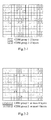
Fig.2-1 illustrates DMRS patterns at the ranks=1-4 as already determined at present in the LTE-A. DRMS patterns at the ranks 5-8 are under ongoing discussion, but substantially it can be determined that in the DMRS patterns at the ranks 5-8, respective DMRS ports will be multiplexed in a Code Division Multiplexing-Frequency Division Multiplexing scheme.Fig.2-2 illustrates an example of the DMRS patterns at the ranks=5-8. - As opposed to the Rel-8/Rel-9, the layer-to-port mapping relationship in the LTE-A is relatively complex in that both a scheme of allocating layers corresponding to respective codewords across respective CDM groups and a relationship between a DMRS pattern and a rate matching module during retransmission have to be taken into account. The method illustrated in
Fig.3 can be adopted at present for the issue of layer-to-port mapping in the LTE-A. Under a mapping principle thereof, layers corresponding to different codewords have to be mapped into different CDM groups. - However the foregoing mapping solution has the following drawbacks:
- (1) At the rank=2, two codewords have to be mapped respectively into different CDM groups under the mapping rule thereof, and this mapping scheme is incompatible with the
transmission mode 8 of the Rel-9, so it is inconvenient to schedule an Rel-9 UE and an Rel-10 UE jointly; - (2) At the rank=2, two codewords have to be mapped respectively into different CDM groups, and therefore a DMRS overhead is increased from 12 pairs of Resource Elements (REs)/Physical Resource Blocks (PRBs) to 24 pairs of REs/PRBs;
- (3) If it is ensured under the principle of the existing solution that a layer corresponding to each codeword can only be put into one CDM group with a DRMS overhead of 12 pairs of REs/PRBs, then only transmission of a single codeword can be supported in transmission at the rank=2; and
- (4) No method of port mapping in retransmission has been considered in the existing solution.
- Therefore it is desired to propose a working solution to mapping to a demodulation reference symbol port while being compatible with an existing system and keeping a lower demodulation reference symbol overhead.
- An object of the invention is to address at least one of the foregoing drawbacks in the prior art, particularly by defining a solution to mapping to a demodulation reference symbol port at the rank=1 to the rank=8 and a solution to mapping to a demodulation reference symbol port in retransmission, so that the solutions to mapping to a demodulation reference symbol port can be compatible with an existing system while keeping a lower demodulation reference symbol overhead.
- In order to attain the foregoing object, an aspect of embodiments of the invention discloses a method of mapping to a demodulation reference symbol port, which includes the steps of:
- a base station assigning a User Equipment, UE, with a corresponding data stream dependent upon an attribute of the UE; the base station mapping the corresponding data stream from a layer to a corresponding demodulation reference symbol port; and the base station transmitting the corresponding data stream to the UE via the demodulation reference symbol port.
- Another aspect of the embodiments of the invention further discloses a base station including a transceiver module and a mapping module, wherein:
- the transceiver module is configured to assign a User Equipment, UE, with a corresponding data stream dependent upon an attribute of the UE; the mapping module is configured to map the corresponding data stream from a layer to a corresponding demodulation reference symbol port; and the transceiver module is further configured to transmit the corresponding data stream to the UE via the demodulation reference symbol port.
- The foregoing solutions proposed by the invention define a solution to mapping to a demodulation reference symbol port at the rank=1 to the rank=8, and a solution to mapping to a demodulation reference symbol port in retransmission, so that the solutions to mapping to a demodulation reference symbol port can be compatible with an existing system while keeping a lower demodulation reference symbol overhead. Furthermore the foregoing solutions proposed by the invention make minor modification to the existing system without any influence upon continual evolvement of the system and can be simple and efficient to implement.
- Additional aspects and advantages of the invention will be partly given in the following description, become partly apparent in the following description or be learned from practicing of the invention.
- The foregoing and/or additional aspects and advantages of the invention will become apparent and readily understood in the following description of the embodiments with reference to the drawings in which:
-
Fig.1 is a process flow chart of a downlink physical channel in the prior art; -
Fig.2-1 illustrates a schematic diagram of DRMS patterns at the ranks=1-4 in the LTE-A in the prior art; -
Fig.2-2 illustrates a schematic diagram of DRMS patterns at the ranks=5-8 in the LTE-A in the prior art; -
Fig.3 is a schematic diagram of a layer-to-DMRS port mapping relationship in the prior art; -
Fig.4 is a flow chart of a method of mapping to a DMRS port according to an embodiment of the invention; -
Fig.5 is a schematic diagram of a layer-to-port mapping relationship at the rank=1 according to an embodiment of the invention; -
Fig.6 is a schematic diagram of a layer-to-port mapping relationship at the rank=2 according to an embodiment of the invention; -
Fig.7 is a schematic diagram of a layer-to-port mapping relationship at the rank=3 according to an embodiment of the invention; -
Fig.8 is a schematic diagram of a layer-to-port mapping relationship at the rank=4 according to an embodiment of the invention; -
Fig.9 is a schematic diagram of a layer-to-port mapping relationship at the rank=5 according to an embodiment of the invention; -
Fig. 10 is a schematic diagram of a layer-to-port mapping relationship at the rank=6 according to an embodiment of the invention; -
Fig. 11 is a schematic diagram of a layer-to-port mapping relationship at the rank=7 according to an embodiment of the invention; -
Fig. 12 is a schematic diagram of a layer-to-port mapping relationship at the rank=8 according to an embodiment of the invention; and -
Fig. 13 is a schematic structural diagram of a base station according to an embodiment of the invention. - Embodiments of the invention will be described below in details, and examples of the embodiments will be illustrated in the drawings throughout which identical or similar reference numerals denote identical or similar elements or elements with identical or similar functions. The embodiments to be described below with reference to the drawings are illustrative and intended to just explain the invention but can not be construed as limiting the invention.
- In order to attain the object of the invention, an embodiment of the invention discloses a method of mapping to a demodulation reference symbol port, which includes the following steps:
- A base station assigns a UE with a corresponding data stream dependent upon an attribute of the UE; the base station maps the corresponding data stream from a layer to a corresponding demodulation reference symbol port; and the base station transmits the corresponding data stream to the UE via the demodulation reference symbol port.
- As illustrated in
Fig.4 which is a flow chart of a method of mapping to a DMRS port according to an embodiment of the invention, which includes the following steps: - S401: A base station determines an attribute of a UE and assigns the UE with a corresponding data stream.
- In the step S401, the base station communicates with the UE and assigns the UE with a corresponding data stream dependent upon an attribute of the UE.
- Specifically during downlink MIMO transmission, the eNB assigns each scheduled UE with a specific number of parallel data streams dependent upon a channel condition, a service characteristic, a priority and other factors of each UE, where each data stream is referred to as a layer. In order to support a Spatial Multiplexing technology of at most 8 layers, an 8-port DMRS will be defined in the LTE-A. The MMRS is processed with the same pre-coding as data, and the UE can know an equivalent channel matrix after pre-coding and demodulate the data by measuring the DMRS. The downlink SU-MIMO of the LTE-A can support at most 8 layers, each of which corresponds to a DMRS port. A process flow of a downlink physical channel is as illustrated in
Fig. 1 . - S402: The base station maps the corresponding data stream from a layer to a corresponding demodulation reference symbol port.
- S403: The base station transmits data to the UE via the demodulation reference symbol port.
- In the step S402, the base station maps the corresponding data stream from a layer to a corresponding demodulation reference symbol port.
- Specifically for downlink transmission at the rank=1, the base station mapping the corresponding data stream from a layer to a corresponding demodulation reference symbol port includes:
- the corresponding data stream can be mapped onto any port and occupy any CDM group.
- As illustrated in
Fig.5 , for example, assumed Multi-User Multi-Input Multi-Output (MU-MIMO) transmission can be supported with M orthogonal DMRS ports in the LTE-A, and then a data layer can be mapped onto any port in {0,...,M} and occupy any CDM group regardless of retransmission or initial transmission.Fig.5 illustrates a layer-to-port mapping scheme with M=4. - For downlink transmission at the rank=2, the base station mapping the corresponding data stream from a layer to a corresponding demodulation reference symbol port includes:
- When downlink transmission is double-codeword transmission at the rank=2, DMRS ports to which two layers correspond belong to the same CDM group. For retransmission of a codeword corresponding to the two layers, it is retransmitted in single-codeword transmission, and the ports occupied for the two layers in retransmission belong to the same CDM group.
- As illustrated in
Fig.6 , for example, in double-codeword transmission at the rank=2, DMRS ports to which two layers correspond shall belong to the same CDM group from the perspective of saving an overhead and improving the reliability of data transmission. A specific group to be occupied is indicated from the eNB side as a result of a scheduling decision. - If double-codeword transmission at the ranks=3-5 were adopted in previous transmission, where a codeword mapped to the
layer 2 will be retransmitted and a transport block corresponding to the other codeword will not be retransmitted, then single-codeword transmission will be adopted in this case. DRMS ports to which the two layers correspond shall belong to the same CDM group. A specific group to be occupied is indicated from the eNB side as a result of a scheduling decision. An occupancy condition of ports in retransmission may be inconsistent with that in initial transmission. - Following this mapping relationship, a DMRS overhead is kept at 12 pairs of Res/PRBs, and this mapping scheme is compatible with the Rel-9 to facilitate joint scheduling.
Fig.6 illustrates an example of a layer-to-port mapping relationship in transmission at the rank=2. - For downlink transmission at the rank=3 or the rank=4, the base station mapping the corresponding data stream from a layer to a corresponding demodulation reference symbol port includes:
- When downlink transmission is double-codeword transmission, a layer to which a
codeword 1 corresponds is mapped to a first demodulation reference symbol CDM group, and a layer to which acodeword 2 corresponds is mapped to a second demodulation reference symbol CDM group. - When downlink transmission is single-codeword transmission, layer-to-demodulation reference symbol port mapping is kept consistent with double-codeword transmission.
- When downlink transmission is double-codeword transmission at the rank=3, if one of the codewords has an error occurring therewith and will be retransmitted and the other codeword has no new data to be transmitted, then a mapping relationship between the layer to which the retransmitted codeword corresponds and the occupied port thereof is defined as that at the rank=1 or the rank=2. A specific example thereof is as illustrated in
Fig.7 . - When downlink transmission is double-codeword transmission at the rank=4, if one of the codewords has an error occurring therewith and will be retransmitted and the other codeword has no new data to be transmitted, then a mapping relationship between the layer to which the retransmitted codeword corresponds and the occupied port thereof is defined as that at the rank=2. A specific example thereof is as illustrated in
Fig.8 . - For downlink transmission at the rank=5, 6, 7 or 8, downlink transmission is double-codeword transmission.
- For downlink transmission at the rank=5, the base station mapping the corresponding data stream from a layer to a corresponding demodulation reference symbol port includes:
- a layer to which a
codeword 1 corresponds is mapped to a first demodulation reference symbol CDM group, and a layer to which acodeword 2 corresponds is mapped to a second demodulation reference symbol CDM group. - When downlink transmission is double-codeword transmission at the rank=5, if one of the codewords has an error occurring therewith and will be retransmitted and the other codeword has no new data to be transmitted, then a mapping relationship between the layer to which the retransmitted codeword corresponds and the occupied port thereof is defined as that at the rank=2 or the rank=3. A specific example thereof is as illustrated in
Fig.9 . - For downlink transmission at the rank=6, the base station mapping the corresponding data stream from a layer to a corresponding demodulation reference symbol port includes:
- a layer to which a
codeword 1 corresponds is mapped to a first demodulation reference symbol CDM group, and a layer to which acodeword 2 corresponds is mapped to a second demodulation reference symbol CDM group. - When downlink transmission is double-codeword transmission at the rank=6, if one of the codewords has an error occurring therewith and will be retransmitted and the other codeword has no new data to be transmitted, then a mapping relationship between the layer to which the retransmitted codeword corresponds and the occupied port thereof is defined as that at the rank=3. A specific example thereof is as illustrated in
Fig.10 . - For downlink transmission at the rank=7, the base station mapping the corresponding data stream from a layer to a corresponding demodulation reference symbol port includes:
- a layer to which a
codeword 1 corresponds is mapped to a first demodulation reference symbol CDM group, and a layer to which acodeword 2 corresponds is mapped to a second demodulation reference symbol CDM group. - When downlink transmission is double-codeword transmission at the rank=7, if one of the codewords has an error occurring therewith and will be retransmitted and the other codeword has no new data to be transmitted, then a mapping relationship between the layer to which the retransmitted codeword corresponds and the occupied port thereof is defined as that at the rank=3 or the rank=4. A specific example thereof is as illustrated in
Fig. 11 . - For downlink transmission at the rank=8, the base station mapping the corresponding data stream from a layer to a corresponding demodulation reference symbol port includes:
- a layer to which a
codeword 1 corresponds is mapped to a first demodulation reference symbol CDM group, and a layer to which acodeword 2 corresponds is mapped to a second demodulation reference symbol CDM group. - When downlink transmission is double-codeword transmission at the rank=8, if one of the codewords has an error occurring therewith and will be retransmitted and the other codeword has no new data to be transmitted, then a mapping relationship between the layer to which the retransmitted codeword corresponds and the occupied port thereof is defined as that at the rank=4. A specific example thereof is as illustrated in
Fig. 12 . - In the step S403, the base station transmits the corresponding data stream to the UE via the demodulation reference symbol port determined in the step S402.
- The foregoing method proposed according to the embodiment of the invention defines a method of mapping to a demodulation reference symbol port at the rank=1 to the rank=8, and a method of mapping to a demodulation reference symbol port in retransmission, so that the methods of mapping to a demodulation reference symbol port can be compatible with an existing system while keeping a lower demodulation reference symbol overhead. Furthermore the foregoing method proposed according to the embodiment of the invention makes minor modification to an existing system without any influence upon continual evolvement of the system and can be simple and efficient to implement.
- As illustrated in
Fig. 13 , an embodiment of the invention further discloses a base station 10 including atransceiver module 110 and amapping module 120. - Particularly the
transceiver module 110 is configured to assign a UE with a corresponding data stream dependent upon an attribute of the UE. - The
mapping module 120 is configured to map the corresponding data stream from a layer to a corresponding demodulation reference symbol port. - Specifically for downlink transmission at the rank=1, the
mapping module 120 mapping the corresponding data stream from a layer to a corresponding demodulation reference symbol port includes: - the corresponding data stream can be mapped onto any port and occupy any CDM group.
- As illustrated in
Fig.5 , for example, assumed MU-MIMO transmission can be supported with M orthogonal DMRS ports in the LTE-A, and then a data layer can be mapped onto any port in {0,...,M} and occupy any CDM group regardless of retransmission or initial transmission.Fig.5 illustrates a layer-to-port mapping scheme with M=4. - For downlink transmission at the rank=2, the
mapping module 120 mapping the corresponding data stream from a layer to a corresponding demodulation reference symbol port includes: - when downlink transmission is double-codeword transmission at the rank=2, DMRS ports to which two layers correspond belong to the same CDM group. For retransmission of a codeword corresponding to the two layers, it is retransmitted in single-codeword transmission, and the ports occupied for the two layers in retransmission belong to the same CDM group.
- As illustrated in
Fig.6 , for example, in double-codeword transmission at the rank=2, DMRS ports to which two layers correspond shall belong to the same CDM group from the perspective of saving an overhead and improving the reliability of data transmission. A specific group to be occupied is indicated from the eNB side as a result of a scheduling decision. - If double-codeword transmission at the ranks=3-5 were adopted in previous transmission, where a codeword mapped to the
layer 2 will be retransmitted and a transport block corresponding to the other codeword will not be retransmitted, then single-codeword transmission will be adopted in this case. DRMS ports to which the two layers correspond shall belong to the same CDM group. A specific group to be occupied is indicated from the eNB side as a result of a scheduling decision. An occupancy condition of ports in retransmission may be inconsistent with that in initial transmission. - Following this mapping relationship, a DMRS overhead is kept at 12 pairs of Res/PRBs, and this mapping scheme is compatible with the Rel-9 to facilitate joint scheduling.
Fig.6 illustrates an example of a layer-to-port mapping relationship in transmission at the rank=2. - For downlink transmission at the rank=3 or the rank=4, the
mapping module 120 mapping the corresponding data stream from a layer to a corresponding demodulation reference symbol port includes: - When downlink transmission is double-codeword transmission, a layer to which a
codeword 1 corresponds is mapped to a first demodulation reference symbol CDM group, and a layer to which acodeword 2 corresponds is mapped to a second demodulation reference symbol CDM group. - When downlink transmission is single-codeword transmission, layer-to-demodulation reference symbol port mapping is kept consistent with double-codeword transmission.
- When downlink transmission is double-codeword transmission at the rank=3, if one of the codewords has an error occurring therewith and will be retransmitted and the other codeword has no new data to be transmitted, then a mapping relationship between the layer to which the retransmitted codeword corresponds and the occupied port thereof is defined as that at the rank=1 or the rank=2. A specific example thereof is as illustrated in
Fig.7 . - When downlink transmission is double-codeword transmission at the rank=4, if one of the codewords has an error occurring therewith and will be retransmitted and the other codeword has no new data to be transmitted, then a mapping relationship between the layer to which the retransmitted codeword corresponds and the occupied port thereof is defined as that at the rank=2. A specific example thereof is as illustrated in
Fig.8 . - For downlink transmission at the rank=5, 6, 7 or 8, downlink transmission is double-codeword transmission.
- For downlink transmission at the rank=5, the
mapping module 120 mapping the corresponding data stream from a layer to a corresponding demodulation reference symbol port includes: - A layer to which a
codeword 1 corresponds is mapped to a first demodulation reference symbol CDM group, and a layer to which acodeword 2 corresponds is mapped to a second demodulation reference symbol CDM group. - When downlink transmission is double-codeword transmission at the rank=5, if one of the codewords has an error occurring therewith and will be retransmitted and the other codeword has no new data to be transmitted, then a mapping relationship between the layer to which the retransmitted codeword corresponds and the occupied port thereof is defined as that at the rank=2 or the rank=3. A specific example thereof is as illustrated in
Fig.9 . - For downlink transmission at the rank=6, the
mapping module 120 mapping the corresponding data stream from a layer to a corresponding demodulation reference symbol port includes: - a layer to which a
codeword 1 corresponds is mapped to a first demodulation reference symbol CDM group, and a layer to which acodeword 2 corresponds is mapped to a second demodulation reference symbol CDM group. - When downlink transmission is double-codeword transmission at the rank=6, if one of the codewords has an error occurring therewith and will be retransmitted and the other codeword has no new data to be transmitted, then a mapping relationship between the layer to which the retransmitted codeword corresponds and the occupied port thereof is defined as that at the rank=3. A specific example thereof is as illustrated in
Fig. 10 . - For downlink transmission at the rank=7, the
mapping module 120 mapping the corresponding data stream from a layer to a corresponding demodulation reference symbol port includes: - a layer to which a
codeword 1 corresponds is mapped to a first demodulation reference symbol CDM group, and a layer to which acodeword 2 corresponds is mapped to a second demodulation reference symbol CDM group. - When downlink transmission is double-codeword transmission at the rank=7, if one of the codewords has an error occurring therewith and will be retransmitted and the other codeword has no new data to be transmitted, then a mapping relationship between the layer to which the retransmitted codeword corresponds and the occupied port thereof is defined as that at the rank=3 or the rank=4. A specific example thereof is as illustrated in
Fig. 11 . - For downlink transmission at the rank=8, the
mapping module 120 mapping the corresponding data stream from a layer to a corresponding demodulation reference symbol port includes: - a layer to which a
codeword 1 corresponds is mapped to a first demodulation reference symbol CDM group, and a layer to which acodeword 2 corresponds is mapped to a second demodulation reference symbol CDM group. - When downlink transmission is double-codeword transmission at the rank=8, if one of the codewords has an error occurring therewith and will be retransmitted and the other codeword has no new data to be transmitted, then a mapping relationship between the layer to which the retransmitted codeword corresponds and the occupied port thereof is defined as that at the rank=4. A specific example thereof is as illustrated in
Fig. 12 . - Thereafter the
transceiver module 110 is further configured to transmit the corresponding data stream to the UE via the demodulation reference symbol port determined by themapping module 120. - The foregoing apparatus proposed according to the embodiment of the invention defines an apparatus for mapping to a demodulation reference symbol port at the rank=1 to the rank=8, and an apparatus for mapping to a demodulation reference symbol port in retransmission, so that the apparatus for mapping to a demodulation reference symbol port can be compatible with an existing system while keeping a lower demodulation reference symbol overhead. Furthermore the foregoing apparatus proposed according to the embodiment of the invention makes minor modification to an existing system without any influence upon continual evolvement of the system and can be simple and efficient to implement.
- Those ordinarily skilled in the art can appreciate that a part or all of the steps in the method according to the embodiment described above can be perform in a program instructing relevant hardware, which can be stored in a computer readable storage medium and which upon execution includes one or a combination of the steps in the method embodiment.
- Furthermore the respective functional units in the respective embodiments of the invention can be integrated in a processing module or the respective units can physically exist separately or two or more of the units can be integrated in a module. The integrated module can be embodied in the form of hardware or in the form of a software functional module. The integrated module can also be stored in a computer readable storage medium if it is embodied in the form of a software functional module and sold or used as a standalone product.
- The storage medium mentioned above can be a read only memory, a magnetic disk, an optical disk, etc.
- The foregoing description is illustrative of the preferred embodiments of the invention, and it shall be noted that those ordinarily skilled in the art can further make several adaptations and modifications without departing from the principal of the invention and these adaptations and modifications shall also be construed as falling into the scope of the invention.
Claims (26)
- A method of mapping to a demodulation reference symbol port, comprising:a base station assigning a User Equipment, UE, with a corresponding data stream dependent upon an attribute of the UE;the base station mapping the corresponding data stream from a layer to a corresponding demodulation reference symbol port; andthe base station transmitting the corresponding data stream to the UE via the demodulation reference symbol port.
- The method of mapping to a demodulation reference symbol port according to claim 1, wherein the base station maps the corresponding data stream from a layer to a corresponding demodulation reference symbol port dependent upon the sequence number of a rank.
- The method of mapping to a demodulation reference symbol port according to claim 2, wherein for downlink transmission at the rank=1, the base station mapping the corresponding data stream from a layer to a corresponding demodulation reference symbol port comprises:mapping the corresponding data stream onto any port and occupying any code division multiplexing, CDM, group.
- The method of mapping to a demodulation reference symbol port according to claim 2, wherein for downlink transmission at the rank=2, the base station mapping the corresponding data stream from a layer to a corresponding demodulation reference symbol port comprises:when downlink transmission is double-codeword transmission at the rank=2, DMRS ports to which two layers correspond belonging to the same code division multiplexing, CDM, group.
- The method of mapping to a demodulation reference symbol port according to claim 4, wherein for retransmission of the same codeword corresponding to the two layers, it is retransmitted in single-codeword transmission, and the ports occupied for the two layers in retransmission belong to the same CDM group.
- The method of mapping to a demodulation reference symbol port according to claim 2, wherein for downlink transmission at the rank=3 or the rank=4, the base station mapping the corresponding data stream from a layer to a corresponding demodulation reference symbol port comprises:when downlink transmission is double-codeword transmission, mapping a layer, to which a codeword 1 corresponds, to a first demodulation reference symbol CDM group, and mapping a layer, to which a codeword 2 corresponds, to a second demodulation reference symbol CDM group; andwhen downlink transmission is single-codeword transmission, keeping layer-to-demodulation reference symbol port mapping consistent with double-codeword transmission.
- The method of mapping to a demodulation reference symbol port according to claim 6, wherein when downlink transmission is double-codeword transmission at the rank=3, if one of the codewords has an error occurring therewith and will be retransmitted and the other codeword has no new data to be transmitted, then a mapping relationship between the layer to which the retransmitted codeword corresponds and the occupied port thereof is defined as that at the rank=1 or the rank=2.
- The method of mapping to a demodulation reference symbol port according to claim 6, wherein when downlink transmission is double-codeword transmission at the rank=4, if one of the codewords has an error occurring therewith and will be retransmitted and the other codeword has no new data to be transmitted, then a mapping relationship between the layer to which the retransmitted codeword corresponds and the occupied port thereof is defined as that at the rank=2.
- The method of mapping to a demodulation reference symbol port according to claim 2, wherein for downlink transmission at the rank=5, the rank=6, the rank=7 or the rank=8, the base station mapping the corresponding data stream from a layer to a corresponding demodulation reference symbol port comprises:mapping a layer, to which a codeword 1 corresponds, to a first demodulation reference symbol CDM group, and mapping a layer, to which a codeword 2 corresponds, to a second demodulation reference symbol CDM group.
- The method of mapping to a demodulation reference symbol port according to claim 9, wherein when downlink transmission is double-codeword transmission at the rank=5, if one of the codewords has an error occurring therewith and will be retransmitted and the other codeword has no new data to be transmitted, then a mapping relationship between the layer to which the retransmitted codeword corresponds and the occupied port thereof is defined as that at the rank=2 or the rank=3.
- The method of mapping to a demodulation reference symbol port according to claim 9, wherein when downlink transmission is double-codeword transmission at the rank=6, if one of the codewords has an error occurring therewith and will be retransmitted and the other codeword has no new data to be transmitted, then a mapping relationship between the layer to which the retransmitted codeword corresponds and the occupied port thereof is defined as that at the rank=3.
- The method of mapping to a demodulation reference symbol port according to claim 9, wherein when downlink transmission is double-codeword transmission at the rank=7, if one of the codewords has an error occurring therewith and will be retransmitted and the other codeword has no new data to be transmitted, then a mapping relationship between the layer to which the retransmitted codeword corresponds and the occupied port thereof is defined as that at the rank=3 or the rank=4.
- The method of mapping to a demodulation reference symbol port according to claim 9, wherein when downlink transmission is double-codeword transmission at the rank=8, if one of the codewords has an error occurring therewith and will be retransmitted and the other codeword has no new data to be transmitted, then a mapping relationship between the layer to which the retransmitted codeword corresponds and the occupied port thereof is defined as that at the rank=4.
- A base station, comprising a transceiver module and a mapping module, wherein:the transceiver module is configured to assign a User Equipment, UE, with a corresponding data stream dependent upon an attribute of the UE;the mapping module is configured to map the corresponding data stream from a layer to a corresponding demodulation reference symbol port; andthe transceiver module is further configured to transmit the corresponding data stream to the UE via the demodulation reference symbol port.
- The base station according to claim 14, wherein the mapping module is further configured to map the corresponding data stream from a layer to a corresponding demodulation reference symbol port dependent upon the sequence number of a rank.
- The base station according to claim 15, wherein for downlink transmission at the rank=1, the mapping module mapping the corresponding data stream from a layer to a corresponding demodulation reference symbol port comprises:mapping the corresponding data stream onto any port and occupying any code division multiplexing, CDM, group.
- The base station according to claim 15, wherein for downlink transmission at the rank=2, the mapping module mapping the corresponding data stream from a layer to a corresponding demodulation reference symbol port comprises:when downlink transmission is double-codeword transmission at the rank=2, DMRS ports to which two layers correspond belonging to the same code division multiplexing CDM group.
- The base station according to claim 17, wherein for retransmission of a codeword corresponding to the two layers, it is retransmitted in single-codeword transmission, and the ports occupied for the two layers in retransmission belong to the same CDM group.
- The base station according to claim 15, wherein for downlink transmission at the rank=3 or the rank=4, the mapping module mapping the corresponding data stream from a layer to a corresponding demodulation reference symbol port comprises:when downlink transmission is double-codeword transmission, mapping a layer, to which a codeword 1 corresponds, to a first demodulation reference symbol CDM group, and mapping a layer, to which a codeword 2 corresponds, to a second demodulation reference symbol CDM group; andwhen downlink transmission is single-codeword transmission, keeping layer-to-demodulation reference symbol port mapping consistent with double-codeword transmission.
- The base station according to claim 19, wherein when downlink transmission is double-codeword transmission at the rank=3, if one of the codewords has an error occurring therewith and will be retransmitted and the other codeword has no new data to be transmitted, then a mapping relationship between the layer to which the retransmitted codeword corresponds and the occupied port thereof is defined as that at the rank=1 or the rank=2.
- The base station according to claim 19, wherein when downlink transmission is double-codeword transmission at the rank=4, if one of the codewords has an error occurring therewith and will be retransmitted and the other codeword has no new data to be transmitted, then a mapping relationship between the layer to which the retransmitted codeword corresponds and the occupied port thereof is defined as that at the rank=2.
- The base station according to claim 15, wherein for downlink transmission at the rank=5, the rank=6, the rank=7 or the rank=8, the mapping module mapping the corresponding data stream from a layer to a corresponding demodulation reference symbol port comprises:mapping a layer, to which a codeword 1 corresponds, to a first demodulation reference symbol CDM group, and mapping a layer, to which a codeword 2 corresponds, to a second demodulation reference symbol CDM group.
- The base station according to claim 22, wherein when downlink transmission is double-codeword transmission at the rank=5, if one of the codewords has an error occurring therewith and will be retransmitted and the other codeword has no new data to be transmitted, then a mapping relationship between the layer to which the retransmitted codeword corresponds and the occupied port thereof is defined as that at the rank=2 or the rank=3.
- The base station according to claim 22, wherein when downlink transmission is double-codeword transmission at the rank=6, if one of the codewords has an error occurring therewith and will be retransmitted and the other codeword has no new data to be transmitted, then a mapping relationship between the layer to which the retransmitted codeword corresponds and the occupied port thereof is defined as that at the rank=3.
- The base station according to claim 22, wherein when downlink transmission is double-codeword transmission at the rank=7, if one of the codewords has an error occurring therewith and will be retransmitted and the other codeword has no new data to be transmitted, then a mapping relationship between the layer to which the retransmitted codeword corresponds and the occupied port thereof is defined as that at the rank=3 or the rank=4.
- The base station according to claim 22, wherein when downlink transmission is double-codeword transmission at the rank=8, if one of the codewords has an error occurring therewith and will be retransmitted and the other codeword has no new data to be transmitted, then a mapping relationship between the layer to which the retransmitted codeword corresponds and the occupied port thereof is defined as that at the rank=4.
Applications Claiming Priority (2)
| Application Number | Priority Date | Filing Date | Title |
|---|---|---|---|
| CN201010112140XA CN102088429B (en) | 2010-02-11 | 2010-02-11 | Method and device for mapping demodulation reference symbol port |
| PCT/CN2011/000191 WO2011097951A1 (en) | 2010-02-11 | 2011-01-31 | Demodulation reference symbol port mapping method and apparatus |
Publications (3)
| Publication Number | Publication Date |
|---|---|
| EP2536090A1 true EP2536090A1 (en) | 2012-12-19 |
| EP2536090A4 EP2536090A4 (en) | 2013-08-07 |
| EP2536090B1 EP2536090B1 (en) | 2015-03-11 |
Family
ID=44100047
Family Applications (1)
| Application Number | Title | Priority Date | Filing Date |
|---|---|---|---|
| EP11741822.8A Active EP2536090B1 (en) | 2010-02-11 | 2011-01-31 | Layer-to-DMRS port mapping for MIMO systems with higher ranks |
Country Status (5)
| Country | Link |
|---|---|
| US (1) | US8837371B2 (en) |
| EP (1) | EP2536090B1 (en) |
| KR (1) | KR101427245B1 (en) |
| CN (1) | CN102088429B (en) |
| WO (1) | WO2011097951A1 (en) |
Families Citing this family (26)
| Publication number | Priority date | Publication date | Assignee | Title |
|---|---|---|---|---|
| WO2012154003A2 (en) * | 2011-05-11 | 2012-11-15 | 엘지전자 주식회사 | Method for transmitting signal using plurality of codewords in wireless communication system and transmission end for same |
| US9807617B2 (en) * | 2011-09-29 | 2017-10-31 | Intel Corporation | Higher order MU-MIMO for LTE-A |
| JP6307434B2 (en) * | 2011-11-16 | 2018-04-04 | サムスン エレクトロニクス カンパニー リミテッド | Method and apparatus for transmitting control information in a wireless communication system |
| WO2014123398A1 (en) * | 2013-02-08 | 2014-08-14 | 엘지전자 주식회사 | Method and user equipment for reporting demodulation reference signal information and method and base station for receiving demodulation reference signal information |
| WO2015096081A1 (en) * | 2013-12-26 | 2015-07-02 | 华为技术有限公司 | Method, device and system for processing data |
| CN105281813B (en) * | 2014-06-16 | 2018-10-26 | 中国移动通信集团公司 | The method and device of transmission data in a kind of multiuser mimo system |
| JP6408614B2 (en) | 2014-06-17 | 2018-10-17 | 華為技術有限公司Huawei Technologies Co.,Ltd. | Signal transmission method and apparatus |
| CN113949484B (en) * | 2015-08-14 | 2023-04-11 | 中兴通讯股份有限公司 | Methods and devices for notifying and determining DMRS (demodulation reference signal) port or mapping relation |
| CN106470088B (en) | 2015-08-14 | 2021-06-15 | 中兴通讯股份有限公司 | Notification and determination method and device of DMRS port or mapping relationship |
| CN106856426B (en) * | 2015-12-09 | 2019-07-19 | 电信科学技术研究院 | DMRS (demodulation reference signal) indication method, terminal and base station |
| CN106973437B (en) | 2016-01-13 | 2021-10-01 | 华为技术有限公司 | Method and device for configuring a reference signal |
| CN107733498B (en) * | 2016-08-11 | 2021-02-12 | 上海诺基亚贝尔股份有限公司 | Method and network device for port mapping for DMRS-based TxD transmission |
| WO2018171538A1 (en) * | 2017-03-24 | 2018-09-27 | 华为技术有限公司 | Data transmission method, network device, and terminal device |
| CN108631815B (en) * | 2017-03-24 | 2021-05-04 | 华为技术有限公司 | Data transmission method, network device and terminal device |
| US10211896B2 (en) | 2017-05-05 | 2019-02-19 | At&T Intellectual Property I, L.P. | Facilitating dynamic layer mapping with multiple downlink control channels for wireless communication systems |
| WO2018230923A1 (en) * | 2017-06-14 | 2018-12-20 | 엘지전자 주식회사 | Method for mapping between codeword and layer in next generation communication system and apparatus therefor |
| CN109995499B (en) | 2017-08-11 | 2020-04-03 | 华为技术有限公司 | Method, receiver, chip, storage medium and communication system for receiving demodulation reference signal |
| WO2019028827A1 (en) * | 2017-08-11 | 2019-02-14 | Panasonic Intellectual Property Corporation Of America | New radio (nr) demodulation reference signal (dmrs) ports mapping and related signaling |
| CN108809609B (en) * | 2017-08-11 | 2019-07-09 | 华为技术有限公司 | A kind of DMRS instruction and method of reseptance, transmitting terminal and receiving end |
| EP3468061A1 (en) * | 2017-10-03 | 2019-04-10 | Panasonic Intellectual Property Corporation of America | Signaling aspects for indication of co-scheduled dmrs ports in mu-mimo |
| CN110034890B (en) | 2018-01-12 | 2020-07-10 | 电信科学技术研究院有限公司 | Data transmission method and device and computer storage medium |
| CN111585720B (en) | 2019-02-15 | 2021-08-27 | 上海朗帛通信技术有限公司 | Method and device used in user equipment and base station for wireless communication |
| WO2020166987A1 (en) * | 2019-02-15 | 2020-08-20 | 엘지전자 주식회사 | Method for receiving codewords in wireless communication system, and apparatus therefor |
| CN120691999A (en) * | 2020-08-14 | 2025-09-23 | 华为技术有限公司 | Signal transmission method and device |
| CN115052346B (en) * | 2021-03-09 | 2026-04-28 | 中国移动通信有限公司研究院 | A mapping method, apparatus, device, and readable storage medium |
| US12627442B2 (en) * | 2022-04-29 | 2026-05-12 | Qualcomm Incorporated | Demodulation reference signal resource allocation |
Family Cites Families (26)
| Publication number | Priority date | Publication date | Assignee | Title |
|---|---|---|---|---|
| TW200908623A (en) * | 2007-06-08 | 2009-02-16 | Qualcomm Inc | Hierarchical modulation for communication channels in single-carrier frequency division multiple access |
| KR101405974B1 (en) * | 2007-08-16 | 2014-06-27 | 엘지전자 주식회사 | Methods for transmitting codewords in multiple input multiple output system |
| CN101374006A (en) * | 2007-08-23 | 2009-02-25 | 中兴通讯股份有限公司 | Multiple-input multiple-output orthogonal frequency division multiplexing system closed-loop spatial multiplexing transmission method and system |
| KR101529736B1 (en) * | 2008-03-05 | 2015-06-29 | 엘지전자 주식회사 | Method of transmitting data in a multi-antenna system |
| CN101572685A (en) | 2008-05-04 | 2009-11-04 | 中兴通讯股份有限公司 | Transmission device used for orthogonal frequency-division multiplexing system |
| US8270518B2 (en) | 2008-07-03 | 2012-09-18 | Texas Instruments Incorporated | Higher order multiple input, multiple output extension |
| US8428018B2 (en) * | 2008-09-26 | 2013-04-23 | Lg Electronics Inc. | Method of transmitting reference signals in a wireless communication having multiple antennas |
| KR101632208B1 (en) * | 2008-11-07 | 2016-06-21 | 엘지전자 주식회사 | Method for transmitting a reference signal |
| WO2010068047A2 (en) * | 2008-12-11 | 2010-06-17 | Lg Electronics Inc. | Method and apparatus for transmitting reference signal performed by relay station in wireless communication system |
| KR101635883B1 (en) * | 2009-02-03 | 2016-07-20 | 엘지전자 주식회사 | Technique for Transmitting and Receiving Downlink Reference Signals |
| KR20100091876A (en) * | 2009-02-11 | 2010-08-19 | 엘지전자 주식회사 | Ue behavior for multi-antenna transmission |
| US8964623B2 (en) * | 2009-04-10 | 2015-02-24 | Lg Electronics Inc. | Transmission method of downlink reference signal and apparatus thereof |
| WO2010117240A2 (en) * | 2009-04-10 | 2010-10-14 | Lg Electronics Inc. | Method and apparatus for transmitting reference signal in wireless communication system |
| US8797950B2 (en) * | 2009-05-27 | 2014-08-05 | Texas Instruments Incorporated | Dual-layer beam forming in cellular networks |
| US9288026B2 (en) * | 2009-06-22 | 2016-03-15 | Qualcomm Incorporated | Transmission of reference signal on non-contiguous clusters of resources |
| JP2012531804A (en) * | 2009-06-26 | 2012-12-10 | エルジー エレクトロニクス インコーポレイティド | Method and apparatus for transmitting reference signal in uplink MIMO transmission |
| CN107104780B (en) * | 2009-10-01 | 2020-10-16 | 交互数字专利控股公司 | Uplink control data transmission |
| US8437300B2 (en) * | 2009-10-12 | 2013-05-07 | Samsung Electronics Co., Ltd | Method and system of multi-layer beamforming |
| KR101789326B1 (en) * | 2009-10-21 | 2017-10-24 | 엘지전자 주식회사 | Method and apparatus of transmitting reference signal in wireless communication system including relay node |
| CN102742191A (en) * | 2009-11-08 | 2012-10-17 | Lg电子株式会社 | A method and a base station for controlling downlink transmission power, and a method and a user equipment for receiving a pdsch |
| WO2011055986A2 (en) * | 2009-11-08 | 2011-05-12 | Lg Electronics Inc. | A method and a base station for transmitting a csi-rs, and a method and a user equipment for receiving the csi-rs |
| US8908617B2 (en) * | 2009-12-31 | 2014-12-09 | Samsung Electronics Co., Ltd. | Uplink demodulation reference signal design for MIMO transmission |
| KR101814394B1 (en) * | 2010-01-17 | 2018-01-03 | 엘지전자 주식회사 | Apparatus and method of transmitting control information in wireless communication system |
| KR101789621B1 (en) * | 2010-01-19 | 2017-10-25 | 엘지전자 주식회사 | A method and a base station for transmitting uplink data, and a method and a user equipment for receiving uplink data |
| CN102714527B (en) * | 2010-01-22 | 2015-04-01 | Lg电子株式会社 | Method and device for providing downlink control information in MIMO wireless communication system |
| US9143883B2 (en) * | 2012-10-31 | 2015-09-22 | Hewlett-Packard Development Company, L.P. | Method and system for improving performance in discovery stage of fast roaming |
-
2010
- 2010-02-11 CN CN201010112140XA patent/CN102088429B/en active Active
-
2011
- 2011-01-31 US US13/578,335 patent/US8837371B2/en active Active
- 2011-01-31 KR KR1020127022540A patent/KR101427245B1/en active Active
- 2011-01-31 EP EP11741822.8A patent/EP2536090B1/en active Active
- 2011-01-31 WO PCT/CN2011/000191 patent/WO2011097951A1/en not_active Ceased
Also Published As
| Publication number | Publication date |
|---|---|
| EP2536090A4 (en) | 2013-08-07 |
| US20120300709A1 (en) | 2012-11-29 |
| KR101427245B1 (en) | 2014-09-22 |
| EP2536090B1 (en) | 2015-03-11 |
| WO2011097951A1 (en) | 2011-08-18 |
| US8837371B2 (en) | 2014-09-16 |
| KR20120125321A (en) | 2012-11-14 |
| CN102088429A (en) | 2011-06-08 |
| CN102088429B (en) | 2013-09-18 |
Similar Documents
| Publication | Publication Date | Title |
|---|---|---|
| US8837371B2 (en) | Method of and apparatus for mapping to demodulation reference signal port | |
| US10299258B2 (en) | Method and apparatus for transmitting control information in wireless communication systems | |
| CN103141146B (en) | Mobile communication system, mobile station device, base station device, communication method, and integrated circuit | |
| AU2012326774B2 (en) | Method and apparatus for transmitting and receiving control information in a wireless communication system | |
| CA2764870C (en) | Mobile communication system, base station apparatus, mobile station apparatus, and mobile communication method | |
| CN108306665B (en) | Method for configuring transmission mode in wireless network | |
| KR102043129B1 (en) | Method and apparatus for allocating harq-ack channel resources supporting transmit diversity and channel selection | |
| JP4959030B2 (en) | Mobile communication system, mobile station apparatus, base station apparatus, and communication method | |
| CN105122716B (en) | Method and apparatus for transmitting channel state information in a wireless communication system | |
| EP2985935A1 (en) | Data sending and receiving method and data sending and receiving end | |
| CN101932025B (en) | Data transmission method for uplink control channels | |
| JP2015188239A (en) | Method for instructing user to use particular dmrs antenna port in radio communication system | |
| CN105992380B (en) | Base station, mobile station, and downlink scheduling method | |
| EP3001743B1 (en) | Method and device for detecting and sending downlink control information | |
| CN114826533B (en) | A method and device for user equipment and base station used for wireless communication | |
| CN113498173A (en) | Method and apparatus in a node used for wireless communication | |
| CN102771170B (en) | Multi-codeword communication method in multi-antenna system | |
| WO2011125391A1 (en) | Mobile communication system, base station device, mobile station device, and communication method | |
| JP2011244397A (en) | Mobile communication system, base station device, mobile station device, and communication method | |
| WO2011099373A1 (en) | Communication method, mobile station device, base station device, mobile communication system, and integrated circuit |
Legal Events
| Date | Code | Title | Description |
|---|---|---|---|
| PUAI | Public reference made under article 153(3) epc to a published international application that has entered the european phase |
Free format text: ORIGINAL CODE: 0009012 |
|
| 17P | Request for examination filed |
Effective date: 20120817 |
|
| AK | Designated contracting states |
Kind code of ref document: A1 Designated state(s): AL AT BE BG CH CY CZ DE DK EE ES FI FR GB GR HR HU IE IS IT LI LT LU LV MC MK MT NL NO PL PT RO RS SE SI SK SM TR |
|
| DAX | Request for extension of the european patent (deleted) | ||
| A4 | Supplementary search report drawn up and despatched |
Effective date: 20130705 |
|
| RIC1 | Information provided on ipc code assigned before grant |
Ipc: H04L 5/00 20060101AFI20130701BHEP |
|
| 17Q | First examination report despatched |
Effective date: 20130819 |
|
| REG | Reference to a national code |
Ref country code: DE Ref legal event code: R079 Ref document number: 602011014632 Country of ref document: DE Free format text: PREVIOUS MAIN CLASS: H04L0027280000 Ipc: H04L0005000000 |
|
| GRAP | Despatch of communication of intention to grant a patent |
Free format text: ORIGINAL CODE: EPIDOSNIGR1 |
|
| RIC1 | Information provided on ipc code assigned before grant |
Ipc: H04L 1/18 20060101ALI20140731BHEP Ipc: H04L 5/00 20060101AFI20140731BHEP |
|
| INTG | Intention to grant announced |
Effective date: 20140901 |
|
| GRAS | Grant fee paid |
Free format text: ORIGINAL CODE: EPIDOSNIGR3 |
|
| GRAA | (expected) grant |
Free format text: ORIGINAL CODE: 0009210 |
|
| AK | Designated contracting states |
Kind code of ref document: B1 Designated state(s): AL AT BE BG CH CY CZ DE DK EE ES FI FR GB GR HR HU IE IS IT LI LT LU LV MC MK MT NL NO PL PT RO RS SE SI SK SM TR |
|
| REG | Reference to a national code |
Ref country code: GB Ref legal event code: FG4D |
|
| REG | Reference to a national code |
Ref country code: CH Ref legal event code: EP |
|
| REG | Reference to a national code |
Ref country code: IE Ref legal event code: FG4D |
|
| REG | Reference to a national code |
Ref country code: AT Ref legal event code: REF Ref document number: 715830 Country of ref document: AT Kind code of ref document: T Effective date: 20150415 |
|
| REG | Reference to a national code |
Ref country code: DE Ref legal event code: R096 Ref document number: 602011014632 Country of ref document: DE Effective date: 20150423 |
|
| REG | Reference to a national code |
Ref country code: NL Ref legal event code: VDEP Effective date: 20150311 |
|
| REG | Reference to a national code |
Ref country code: NL Ref legal event code: VDEP Effective date: 20150311 |
|
| PG25 | Lapsed in a contracting state [announced via postgrant information from national office to epo] |
Ref country code: ES Free format text: LAPSE BECAUSE OF FAILURE TO SUBMIT A TRANSLATION OF THE DESCRIPTION OR TO PAY THE FEE WITHIN THE PRESCRIBED TIME-LIMIT Effective date: 20150311 Ref country code: FI Free format text: LAPSE BECAUSE OF FAILURE TO SUBMIT A TRANSLATION OF THE DESCRIPTION OR TO PAY THE FEE WITHIN THE PRESCRIBED TIME-LIMIT Effective date: 20150311 Ref country code: NO Free format text: LAPSE BECAUSE OF FAILURE TO SUBMIT A TRANSLATION OF THE DESCRIPTION OR TO PAY THE FEE WITHIN THE PRESCRIBED TIME-LIMIT Effective date: 20150611 Ref country code: HR Free format text: LAPSE BECAUSE OF FAILURE TO SUBMIT A TRANSLATION OF THE DESCRIPTION OR TO PAY THE FEE WITHIN THE PRESCRIBED TIME-LIMIT Effective date: 20150311 Ref country code: LT Free format text: LAPSE BECAUSE OF FAILURE TO SUBMIT A TRANSLATION OF THE DESCRIPTION OR TO PAY THE FEE WITHIN THE PRESCRIBED TIME-LIMIT Effective date: 20150311 Ref country code: SE Free format text: LAPSE BECAUSE OF FAILURE TO SUBMIT A TRANSLATION OF THE DESCRIPTION OR TO PAY THE FEE WITHIN THE PRESCRIBED TIME-LIMIT Effective date: 20150311 |
|
| REG | Reference to a national code |
Ref country code: AT Ref legal event code: MK05 Ref document number: 715830 Country of ref document: AT Kind code of ref document: T Effective date: 20150311 |
|
| REG | Reference to a national code |
Ref country code: LT Ref legal event code: MG4D |
|
| PG25 | Lapsed in a contracting state [announced via postgrant information from national office to epo] |
Ref country code: RS Free format text: LAPSE BECAUSE OF FAILURE TO SUBMIT A TRANSLATION OF THE DESCRIPTION OR TO PAY THE FEE WITHIN THE PRESCRIBED TIME-LIMIT Effective date: 20150311 Ref country code: LV Free format text: LAPSE BECAUSE OF FAILURE TO SUBMIT A TRANSLATION OF THE DESCRIPTION OR TO PAY THE FEE WITHIN THE PRESCRIBED TIME-LIMIT Effective date: 20150311 Ref country code: GR Free format text: LAPSE BECAUSE OF FAILURE TO SUBMIT A TRANSLATION OF THE DESCRIPTION OR TO PAY THE FEE WITHIN THE PRESCRIBED TIME-LIMIT Effective date: 20150612 |
|
| PG25 | Lapsed in a contracting state [announced via postgrant information from national office to epo] |
Ref country code: NL Free format text: LAPSE BECAUSE OF FAILURE TO SUBMIT A TRANSLATION OF THE DESCRIPTION OR TO PAY THE FEE WITHIN THE PRESCRIBED TIME-LIMIT Effective date: 20150311 |
|
| PG25 | Lapsed in a contracting state [announced via postgrant information from national office to epo] |
Ref country code: CZ Free format text: LAPSE BECAUSE OF FAILURE TO SUBMIT A TRANSLATION OF THE DESCRIPTION OR TO PAY THE FEE WITHIN THE PRESCRIBED TIME-LIMIT Effective date: 20150311 Ref country code: SK Free format text: LAPSE BECAUSE OF FAILURE TO SUBMIT A TRANSLATION OF THE DESCRIPTION OR TO PAY THE FEE WITHIN THE PRESCRIBED TIME-LIMIT Effective date: 20150311 Ref country code: EE Free format text: LAPSE BECAUSE OF FAILURE TO SUBMIT A TRANSLATION OF THE DESCRIPTION OR TO PAY THE FEE WITHIN THE PRESCRIBED TIME-LIMIT Effective date: 20150311 Ref country code: PT Free format text: LAPSE BECAUSE OF FAILURE TO SUBMIT A TRANSLATION OF THE DESCRIPTION OR TO PAY THE FEE WITHIN THE PRESCRIBED TIME-LIMIT Effective date: 20150713 Ref country code: RO Free format text: LAPSE BECAUSE OF FAILURE TO SUBMIT A TRANSLATION OF THE DESCRIPTION OR TO PAY THE FEE WITHIN THE PRESCRIBED TIME-LIMIT Effective date: 20150311 |
|
| PG25 | Lapsed in a contracting state [announced via postgrant information from national office to epo] |
Ref country code: AT Free format text: LAPSE BECAUSE OF FAILURE TO SUBMIT A TRANSLATION OF THE DESCRIPTION OR TO PAY THE FEE WITHIN THE PRESCRIBED TIME-LIMIT Effective date: 20150311 Ref country code: PL Free format text: LAPSE BECAUSE OF FAILURE TO SUBMIT A TRANSLATION OF THE DESCRIPTION OR TO PAY THE FEE WITHIN THE PRESCRIBED TIME-LIMIT Effective date: 20150311 Ref country code: IS Free format text: LAPSE BECAUSE OF FAILURE TO SUBMIT A TRANSLATION OF THE DESCRIPTION OR TO PAY THE FEE WITHIN THE PRESCRIBED TIME-LIMIT Effective date: 20150711 |
|
| REG | Reference to a national code |
Ref country code: DE Ref legal event code: R097 Ref document number: 602011014632 Country of ref document: DE |
|
| PG25 | Lapsed in a contracting state [announced via postgrant information from national office to epo] |
Ref country code: IT Free format text: LAPSE BECAUSE OF FAILURE TO SUBMIT A TRANSLATION OF THE DESCRIPTION OR TO PAY THE FEE WITHIN THE PRESCRIBED TIME-LIMIT Effective date: 20150311 |
|
| PLBE | No opposition filed within time limit |
Free format text: ORIGINAL CODE: 0009261 |
|
| STAA | Information on the status of an ep patent application or granted ep patent |
Free format text: STATUS: NO OPPOSITION FILED WITHIN TIME LIMIT |
|
| PG25 | Lapsed in a contracting state [announced via postgrant information from national office to epo] |
Ref country code: DK Free format text: LAPSE BECAUSE OF FAILURE TO SUBMIT A TRANSLATION OF THE DESCRIPTION OR TO PAY THE FEE WITHIN THE PRESCRIBED TIME-LIMIT Effective date: 20150311 |
|
| REG | Reference to a national code |
Ref country code: FR Ref legal event code: PLFP Year of fee payment: 6 |
|
| 26N | No opposition filed |
Effective date: 20151214 |
|
| PG25 | Lapsed in a contracting state [announced via postgrant information from national office to epo] |
Ref country code: SI Free format text: LAPSE BECAUSE OF FAILURE TO SUBMIT A TRANSLATION OF THE DESCRIPTION OR TO PAY THE FEE WITHIN THE PRESCRIBED TIME-LIMIT Effective date: 20150311 |
|
| PG25 | Lapsed in a contracting state [announced via postgrant information from national office to epo] |
Ref country code: LU Free format text: LAPSE BECAUSE OF FAILURE TO SUBMIT A TRANSLATION OF THE DESCRIPTION OR TO PAY THE FEE WITHIN THE PRESCRIBED TIME-LIMIT Effective date: 20160131 |
|
| REG | Reference to a national code |
Ref country code: CH Ref legal event code: PL |
|
| PG25 | Lapsed in a contracting state [announced via postgrant information from national office to epo] |
Ref country code: MC Free format text: LAPSE BECAUSE OF FAILURE TO SUBMIT A TRANSLATION OF THE DESCRIPTION OR TO PAY THE FEE WITHIN THE PRESCRIBED TIME-LIMIT Effective date: 20150311 |
|
| PG25 | Lapsed in a contracting state [announced via postgrant information from national office to epo] |
Ref country code: LI Free format text: LAPSE BECAUSE OF NON-PAYMENT OF DUE FEES Effective date: 20160131 Ref country code: CH Free format text: LAPSE BECAUSE OF NON-PAYMENT OF DUE FEES Effective date: 20160131 |
|
| REG | Reference to a national code |
Ref country code: IE Ref legal event code: MM4A |
|
| PG25 | Lapsed in a contracting state [announced via postgrant information from national office to epo] |
Ref country code: IE Free format text: LAPSE BECAUSE OF NON-PAYMENT OF DUE FEES Effective date: 20160131 |
|
| REG | Reference to a national code |
Ref country code: FR Ref legal event code: PLFP Year of fee payment: 7 |
|
| PG25 | Lapsed in a contracting state [announced via postgrant information from national office to epo] |
Ref country code: MT Free format text: LAPSE BECAUSE OF FAILURE TO SUBMIT A TRANSLATION OF THE DESCRIPTION OR TO PAY THE FEE WITHIN THE PRESCRIBED TIME-LIMIT Effective date: 20150311 |
|
| REG | Reference to a national code |
Ref country code: FR Ref legal event code: PLFP Year of fee payment: 8 |
|
| PG25 | Lapsed in a contracting state [announced via postgrant information from national office to epo] |
Ref country code: SM Free format text: LAPSE BECAUSE OF FAILURE TO SUBMIT A TRANSLATION OF THE DESCRIPTION OR TO PAY THE FEE WITHIN THE PRESCRIBED TIME-LIMIT Effective date: 20150311 Ref country code: HU Free format text: LAPSE BECAUSE OF FAILURE TO SUBMIT A TRANSLATION OF THE DESCRIPTION OR TO PAY THE FEE WITHIN THE PRESCRIBED TIME-LIMIT; INVALID AB INITIO Effective date: 20110131 Ref country code: CY Free format text: LAPSE BECAUSE OF FAILURE TO SUBMIT A TRANSLATION OF THE DESCRIPTION OR TO PAY THE FEE WITHIN THE PRESCRIBED TIME-LIMIT Effective date: 20150311 |
|
| PG25 | Lapsed in a contracting state [announced via postgrant information from national office to epo] |
Ref country code: TR Free format text: LAPSE BECAUSE OF FAILURE TO SUBMIT A TRANSLATION OF THE DESCRIPTION OR TO PAY THE FEE WITHIN THE PRESCRIBED TIME-LIMIT Effective date: 20150311 Ref country code: MK Free format text: LAPSE BECAUSE OF FAILURE TO SUBMIT A TRANSLATION OF THE DESCRIPTION OR TO PAY THE FEE WITHIN THE PRESCRIBED TIME-LIMIT Effective date: 20150311 |
|
| PG25 | Lapsed in a contracting state [announced via postgrant information from national office to epo] |
Ref country code: BG Free format text: LAPSE BECAUSE OF FAILURE TO SUBMIT A TRANSLATION OF THE DESCRIPTION OR TO PAY THE FEE WITHIN THE PRESCRIBED TIME-LIMIT Effective date: 20150311 |
|
| PG25 | Lapsed in a contracting state [announced via postgrant information from national office to epo] |
Ref country code: AL Free format text: LAPSE BECAUSE OF FAILURE TO SUBMIT A TRANSLATION OF THE DESCRIPTION OR TO PAY THE FEE WITHIN THE PRESCRIBED TIME-LIMIT Effective date: 20150311 |
|
| REG | Reference to a national code |
Ref country code: DE Ref legal event code: R081 Ref document number: 602011014632 Country of ref document: DE Owner name: DATANG MOBILE COMMUNICATIONS EQUIPMENT CO., LT, CN Free format text: FORMER OWNER: CHINA ACADEMY OF TELECOMMUNICATIONS TECHNOLOGY, BEIJING, CN |
|
| REG | Reference to a national code |
Ref country code: BE Ref legal event code: PD Owner name: DATANG MOBILE COMMUNICATIONS EQUIPMENT CO., LTD.; CN Free format text: DETAILS ASSIGNMENT: CHANGE OF OWNER(S), ASSIGNMENT; FORMER OWNER NAME: CHINA ACADEMY OF TELECOMMUNICATIONS TECHNOLOGY Effective date: 20210816 |
|
| REG | Reference to a national code |
Ref country code: GB Ref legal event code: 732E Free format text: REGISTERED BETWEEN 20211007 AND 20211013 |
|
| P01 | Opt-out of the competence of the unified patent court (upc) registered |
Effective date: 20230512 |
|
| PGFP | Annual fee paid to national office [announced via postgrant information from national office to epo] |
Ref country code: GB Payment date: 20260123 Year of fee payment: 16 |
|
| PGFP | Annual fee paid to national office [announced via postgrant information from national office to epo] |
Ref country code: DE Payment date: 20260121 Year of fee payment: 16 |
|
| PGFP | Annual fee paid to national office [announced via postgrant information from national office to epo] |
Ref country code: BE Payment date: 20260121 Year of fee payment: 16 |
|
| PGFP | Annual fee paid to national office [announced via postgrant information from national office to epo] |
Ref country code: FR Payment date: 20260123 Year of fee payment: 16 |