EP2536036A1 - Device and method for calibrating reciprocity errors - Google Patents
Device and method for calibrating reciprocity errors Download PDFInfo
- Publication number
- EP2536036A1 EP2536036A1 EP10845459A EP10845459A EP2536036A1 EP 2536036 A1 EP2536036 A1 EP 2536036A1 EP 10845459 A EP10845459 A EP 10845459A EP 10845459 A EP10845459 A EP 10845459A EP 2536036 A1 EP2536036 A1 EP 2536036A1
- Authority
- EP
- European Patent Office
- Prior art keywords
- reciprocity
- algorithm
- reciprocity error
- calibration
- error
- Prior art date
- Legal status (The legal status is an assumption and is not a legal conclusion. Google has not performed a legal analysis and makes no representation as to the accuracy of the status listed.)
- Withdrawn
Links
Images


Classifications
-
- H—ELECTRICITY
- H04—ELECTRIC COMMUNICATION TECHNIQUE
- H04B—TRANSMISSION
- H04B17/00—Monitoring; Testing
- H04B17/20—Monitoring; Testing of receivers
- H04B17/21—Monitoring; Testing of receivers for calibration; for correcting measurements
-
- H—ELECTRICITY
- H04—ELECTRIC COMMUNICATION TECHNIQUE
- H04B—TRANSMISSION
- H04B17/00—Monitoring; Testing
- H04B17/10—Monitoring; Testing of transmitters
- H04B17/11—Monitoring; Testing of transmitters for calibration
-
- H—ELECTRICITY
- H04—ELECTRIC COMMUNICATION TECHNIQUE
- H04L—TRANSMISSION OF DIGITAL INFORMATION, e.g. TELEGRAPHIC COMMUNICATION
- H04L25/00—Baseband systems
- H04L25/02—Details ; arrangements for supplying electrical power along data transmission lines
- H04L25/0202—Channel estimation
- H04L25/0212—Channel estimation of impulse response
-
- H—ELECTRICITY
- H04—ELECTRIC COMMUNICATION TECHNIQUE
- H04B—TRANSMISSION
- H04B17/00—Monitoring; Testing
- H04B17/10—Monitoring; Testing of transmitters
- H04B17/11—Monitoring; Testing of transmitters for calibration
- H04B17/12—Monitoring; Testing of transmitters for calibration of transmit antennas, e.g. of the amplitude or phase
-
- H—ELECTRICITY
- H04—ELECTRIC COMMUNICATION TECHNIQUE
- H04B—TRANSMISSION
- H04B17/00—Monitoring; Testing
- H04B17/10—Monitoring; Testing of transmitters
- H04B17/11—Monitoring; Testing of transmitters for calibration
- H04B17/14—Monitoring; Testing of transmitters for calibration of the whole transmission and reception path, e.g. self-test loop-back
-
- H—ELECTRICITY
- H04—ELECTRIC COMMUNICATION TECHNIQUE
- H04L—TRANSMISSION OF DIGITAL INFORMATION, e.g. TELEGRAPHIC COMMUNICATION
- H04L25/00—Baseband systems
- H04L25/02—Details ; arrangements for supplying electrical power along data transmission lines
- H04L25/0202—Channel estimation
- H04L25/024—Channel estimation channel estimation algorithms
- H04L25/0256—Channel estimation using minimum mean square error criteria
Definitions
- the present invention relates to wireless communication systems, and specifically to a reciprocity error calibration device and a reciprocity error calibration method.
- Channel reciprocity is one of key features of time-division multiplexing TDD systems, which plays a significant role in most TDD (for example, TD-SCDMA, WiMAX, WiFi, etc.) systems and enables the implementation of variety of advanced signal processings (beamforming, MIMO, transmit diversity, etc.).
- TDD time-division multiplexing
- MIMO massive MIMO
- transmit diversity etc.
- a plurality of factors would affect the reciprocity errors of uplinks and downlinks, including transceiver mismatch, Doppler effect due to mobility, asymmetric interference etc. It is required to reduce the reciprocity errors through antenna array reciprocity error calibration.
- a technical problem to be solved by the present invention is to provide a calibration method that can achieve optimal performance.
- This method has a stronger robustness and a high precision, and may be applied for advanced processing in the TDD system, for example, beamforming, MU-MIMO, and CoMP, etc.
- the algorithm adopting LS criterion is an elementary least square ELS algorithm.
- the algorithm adopting MMSE criterion is one of a matrix least square MLS algorithm and a matrix MMSE algorithm.
- the further algorithm adopting MMSE criterion is one of a matrix least square MLS algorithm and a matrix MMSE algorithm.
- the method is performed at a user equipment or a base station.
- a UE/eNB reciprocity calibration solution for TDD systems which is applicable to a single cell or CoMP scenario.
- the reciprocity error calibration method and the reciprocity error calibration device according to the embodiments of the present invention may provide a better reciprocity error calibration and improve the performance of the channel reciprocity-based TDD systems, especially in a normally working SNR range.
- Uplink (UL)/downlink (DL) channel reciprocity is one of key features of a TDD system.
- transmit (TX)/receive (RX) radio frequency (RF) circuit mismatch in UE and eNB Doppler asymmetry due to mobility, and estimation algorithm error between UE and eNB may cause channel reciprocity between UL and DL does not necessarily always exist.
- antenna array reciprocity error calibration is required to satisfy needs under various situations.
- Self calibration does not require air-interface signaling and can provide full band accurate RF mismatch calibration, and thus has been deployed in many TDD systems.
- Over-the-air calibration is a pure software calibration, and typically does not require any hardware support. Most importantly, over-the-air calibration does not require absolute reciprocity measurement in a distributed antenna system, and thus OTA Cal has attracted great interests from 3GPP LTE-A community.
- Fig. 1 illustrates a structural diagram of a conventional TDD system equipped with a self-calibration circuit.
- TX and RX represent a transmitter and a receiver, respectively;
- CTX and CRX represent a calibration transmitter and a calibration receiver, respectively;
- the TR Switch represents a transmit/ receive switch;
- Base Band represents a base band processing circuit.
- Fig. 1 mainly illustrates the reciprocity calibration at a base station eNB side.
- the following narrow band variables may be defined:
- w 1 may be selected as a reference reciprocity of the eNB, and w i as a calibration weight for the ith antenna.
- Fig. 2 illustrates a schematic diagram of the structures of a base station eNB and a user equipment UE in a conventional over-the-air calibration-enabled TDD system and the calibration signaling therebetween.
- TX and RX represent a transmitter and a receiver, respectively; and
- TR Switch represents a transmit/receive switch. The following variables may be defined:
- w 1 may be selected as a reference reciprocity of the eNB, and w i as the calibration weight for the ith antenna.
- a logic channel should be allocated on the eNB to eNB link (for example, X.2) for transmitting a global reference reciprocity.
- the global reference may be an absolute reciprocity of a certain calibrated TX response/RX response.
- the global reference may be a measured reciprocity of any antenna branch of the eNB participating into the calibration (see literature [3]).
- the over-the-air calibration is assumed to direct to systems with a location-centralized antenna array.
- the new technology may be directly extended to a distributed over-the-air calibration system or a self-calibration scenario in either collectively located or distributed antenna array system, e.g., by taking the calibration transceiver(s) as the UE and the hardware calibration network as the air interface channels, and exchanging global references via the backhaul link if needed.
- the eNB For the over-the-air reciprocity calibration, due to its hardware advantage over UE, it is usually the eNB that takes charge of collecting uplink and downlink channel measurements and calculating the reciprocity calibration weight.
- the calibration operation is performed in the eNB, which, however, is not intended to exclude the possibility of performing calibration in the UE (see the literature [4]).
- the present invention is equally applicable for the scenario of performing calibration at UE.
- Literature [3] proposes an over-the-air calibration technical solution for LTE and LTE-A systems.
- the objective is to guarantee the least square LS error based on a simple dot-division.
- both the UE side and BS side reciprocity errors should be calibrated simultaneously.
- a basic idea of the present invention lies in after calculating the reciprocity-calibrated channel response of the uplink (downlink) channel according to a known calibration algorithm (for example, an algorithm adopting the LS criterion), using an algorithm adopting a more optimal criterion to estimate reciprocity errors.
- the idea of the present invention may be applied to both the over-the-air calibration and the self-calibration.
- the more optimal criterion may be a minimum mean square error (MMSE) criterion
- the algorithm adopting the more optimal criterion may be for example a matrix least-square (MLS) algorithm and a matrix MMSE algorithm.
- Fig. 3 shows a schematic block diagram of a system model according to the embodiments of the present invention.
- a radio transmitter has a RF circuit different from that of the radio receiver. It is assumed that the coupling effect between antennas is relatively weak relative to the response of the antenna unit itself.
- , for any i ⁇ j, i, j 1 , ...,L, where L is the number of antennas participating in the calibration.
- H DL H mr ⁇ H AI
- DL ⁇ H bt H UL H br ⁇ H AI , DL ⁇ H mt
- H DL H mr ⁇ H mt - T ⁇ H UL T ⁇ H br - T ⁇ H bt
- the equation (5) provides a model for reciprocity between the actual uplink and downlink.
- the objective of the reciprocity error calibration is to calculate the eNB side reciprocity error E b and the UE side reciprocity error E m , and apply them to compensate user signals so as to use H UL to predict H DL so as to guarantee the reciprocity between H DL and H UL ; vice versa.
- H DL and H UL may be measured through reference signals, for example, the downlink channel condition information reference signal CSI-RS and uplink reference signal SRS in LTE-A.
- CSI-RS downlink channel condition information reference signal
- SRS uplink reference signal
- H ⁇ DL A l ⁇ H DL ⁇ A r + N DL
- H ⁇ DL A l ⁇ E m - 1 ⁇ B r - T ⁇ H ⁇ UL T ⁇ B l - T ⁇ E b ⁇ A r + N DL - A l ⁇ E m - 1 ⁇ B l - T ⁇ N UL T ⁇ B r - T ⁇ E b ⁇ A r .
- E l - 1 A l ⁇ E m - 1 ⁇ B r - T
- E r B l - T ⁇ E b ⁇ A r
- N E N DL - E l - 1 ⁇ N UL T ⁇ E r
- H ⁇ DL E l - 1 ⁇ H ⁇ UL T ⁇ E r + E E
- N E is a matrix whose elements follow independent complex Gaussian distribution with CN (0, ⁇ N E 2 ).
- E m (identical to the estimation of E l with supposition (4)) may be first estimated through the elementary least square ELS (literature [4]) estimation algorithm , to eliminate the association between E m and E b .
- E b (identical to the estimation of E r with supposition 4)) may be estimated by utilizing the matrix least square (MLS) estimation algorithm, the matrix minimum mean square error (MMSE) estimation algorithm or other variants thereof.
- MLS matrix least square
- MMSE matrix minimum mean square error
- the advantage of the MMSE-based estimation algorithm over the ELS algorithm adopted in literature [4] lies in that it does not need the establishment of supposition (3), and thus it will better conform to the actual conditions, thereby capable of providing a better reciprocity error calibration performance.
- E ⁇ r R E r ⁇ E r ⁇ R E r ⁇ E r + ⁇ E l ⁇ N 2 ⁇ H ⁇ UL H ⁇ H ⁇ UL - 1 - 1 ⁇ H ⁇ UL T + ⁇ E ⁇ l ⁇ H ⁇ DL
- R E , E , E r ⁇ E r H is the second order statistic (auto-covariance) of E r
- ⁇ E l ⁇ N 2 is the power density of the noise
- E ⁇ l ⁇ N E E ⁇ l ⁇ N D ⁇ L - E ⁇ l ⁇ E l ⁇ N U ⁇ L T ⁇ E r which can be approximated by ⁇ U ⁇ L 2 + ⁇ D ⁇ L 2 .
- R E r E r can be calculated from previous estimations of ⁇ r .
- Fig. 4 illustrates a flow chart of a reciprocity error calibration method according to the embodiments of the present invention.
- step S101 the UE measures downlink channel response H DL from all of its antennas and feeds the measured H DL to eNB.
- the measured H DL may be fed back to eNB through the channel state information (CSI).
- CSI channel state information
- step S102 the eNB measures the uplink channel response H UL based on the uplink reference signal (sounding reference signal, SRS).
- uplink reference signal sounding reference signal, SRS
- the eNB may calculate the user equipment reciprocity error E m utilizing the ELS algorithm in accordance with the above equations (6) ⁇ (8).
- step S104 the eNB utilizes another algorithm adopting the MMSE criterion to calculate the other one of E m and E b based on the calculated one of the E m and E b .
- the eNB calculates the base station reciprocity error E b utilizing the matrix LS algorithm or the matrix MMSE algorithm based on the calculated user equipment reciprocity error E m .
- step S105 the eNB performs the reciprocity error calibration operation based on the calculated user equipment reciprocity error E m and base station reciprocity error E b .
- step S104 the other one of E m and E b is calculated, without the supposition, based on the calculated one of E m and E b utilizing the MLS or matrix MMSE.
- Fig. 5 illustrates a block diagram of a reciprocity error calibration device according to the embodiments of the present invention.
- the reciprocity error calibration method and reciprocity error calibration device according to the embodiments of the present invention as described with reference to Fig. 4 and Fig. 5 are illustrated to be implemented at the eNB. However, those skilled in the art would appreciate that the present invention is not limited thereto.
- the reciprocity error calibration method and reciprocity error calibration device according to the embodiments of the present invention may also be implemented at the UE.
- the downlink measurement module 101 may be disposed at the UE.
- the reciprocity error calibration device further comprises a transmitting module disposed at the UE, configured to transmit to the eNB the downlink channel responses H DL measured by the UE from all of its antennas; and a receiving module disposed at the eNB, configured to receive the downlink channel response H DL from the UE.
- LTA-A link 3 UEs, 3eNBs, each UE equipped with two antennas, each eNB equipped with 4 antennas, 16QAM, Turbo code, 1mps speed, Urban micro cell scenario, -5dB inter-cell interference, 6-bit channel quantization for feedback.
- Fig. 6 illustrates simulation results from comparing the reciprocity error calibration method according to the embodiments of the present invention and the conventional reciprocity error calibration method.
- the Signal to Interference plus Noise Ratio (SINR) of a demodulator input signals is utilized as a performance metric.
- SINR Signal to Interference plus Noise Ratio
- SRS w/o RE indicates a channel measurement result without reciprocity error
- ELS eNB + UE Cal indicates a channel measurement result of performing the reciprocity error calibration to both the base station and the terminal utilizing the ELS estimation algorithm
- LS eNB Cal indicates the channel measurement result of merely performing LS reciprocity error calibration to eNB
- RE w/o Cal indicates the channel measurement result without applying any reciprocity error calibration
- MLS eNB + UE Cal indicates the channel measurement result of performing reciprocity error calibration to both the base station and the terminal utilizing the MLS estimation algorithm
- MMSE eNB+UE Cal indicates the channel estimation result of performing the reciprocity error calibration to both the base station and the terminal utilizing the MMSE estimation algorithm.
- the MMSE estimation algorithm at the eNB side may realize almost perfect performance, particularly in the working SNR scope (0dB-20dB).
- the matrix LS (MLS) estimation algorithm may also provide a greater gain at low SNR.
- a link gain of about 2dB may be realized.
- iterative estimation on the UE side reciprocity error and the eNB side reciprocity error may be performed based on the aforementioned model.
- the ELS estimation algorithm may be used to estimate E m
- the MMSE estimation algorithm is used to estimate E b
- E m is updated using the matrix MMSE estimation algorithm.
- the process may also be started from the ELS estimation algorithm of E b , i.e., using the ELS estimation algorithm to estimate E b , and then using the MMSE estimation algorithm to estimate E m , and next, using the matrix MMSE estimation algorithm to update E b .
- the present invention provides a UE/eNB reciprocity calibration solution for TDD systems, which is applicable to a single cell or CoMP scenario, such that the performance of channel reciprocity-based TDD systems is improved, particularly in a normally working SNR range.
- each step as illustrated in Fig. 4 may be implemented by one or more functional modules as illustrated in Fig. 5 .
- the functional modules may also be integrated into one chip or one device in actual application.
- a person of normal skill in the art should understand that the base station in the embodiments of the present invention may also include any units or modules for other purposes.
- Some embodiments are also intended to cover machine or computer readable program storage devices, e.g., digital data storage media, and encoded machine executable or computer executable programs of instructions, wherein said instructions perform some or all of the steps of said above described methods.
- the program storage devices may be, e.g., digital storage, magnetic storage media such as magnetic disks and magnetic tapes, hard drives, or optically readable digital data storage media.
- the embodiments are also intended to cover computers programmed to execute programs recorded on storage media to perform said steps of the above described methods.
Landscapes
- Engineering & Computer Science (AREA)
- Computer Networks & Wireless Communication (AREA)
- Signal Processing (AREA)
- Physics & Mathematics (AREA)
- Electromagnetism (AREA)
- Power Engineering (AREA)
- Mobile Radio Communication Systems (AREA)
- Monitoring And Testing Of Transmission In General (AREA)
Abstract
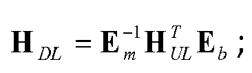
Description
- The present invention relates to wireless communication systems, and specifically to a reciprocity error calibration device and a reciprocity error calibration method.
- Channel reciprocity is one of key features of time-division multiplexing TDD systems, which plays a significant role in most TDD (for example, TD-SCDMA, WiMAX, WiFi, etc.) systems and enables the implementation of variety of advanced signal processings (beamforming, MIMO, transmit diversity, etc.). In practice, a plurality of factors would affect the reciprocity errors of uplinks and downlinks, including transceiver mismatch, Doppler effect due to mobility, asymmetric interference etc. It is required to reduce the reciprocity errors through antenna array reciprocity error calibration.
- Due to use of a joint processing method (for example, coordinated multi-point processing CoMP), the requirement on the precision of calibration method becomes higher. For example, the conventional calibration method as described in literature [2] cannot meet the performance requirement of joint processing.
- Thus, a technical problem to be solved by the present invention is to provide a calibration method that can achieve optimal performance. This method has a stronger robustness and a high precision, and may be applied for advanced processing in the TDD system, for example, beamforming, MU-MIMO, and CoMP, etc.
-
- 1. Jian Liu, et al., "OFDM-MIMO WLAN AP Front-end Gain and Phase Mismatch Calibration," Proc. IEEE RAWCON, Sep. 2004
- 2. A. Bourdoux, B. Come, N. Khaled, Non-reciprocal transceivers in OFDM/SDMA Systems: Impact and Mitigation, in Proc. IEEE Radio and Wireless Conference, Boston, MA, USA, August 2003, pp. 183-186.
- 3. 3GPP RAN1 Tdoc for LTE and LTE-A, R1-094622, R1-093026, R1-080494, R1-090563, R1-093378, R1-094623, 2009
- 4. 3GPP RAN1 Tdoc for LTE and LTE-A, R1-100932
- According to a first aspect of the present invention, there is provided a method for reciprocity error calibration, comprising steps of: measuring downlink channel response H DL; measuring uplink channel response H UL; calculating one of a user equipment reciprocity error E m and a base station reciprocity error E b utilizing least square LS criterion based on the H DL and H UL in accordance with a reciprocity model

- Preferably, the algorithm adopting LS criterion is an elementary least square ELS algorithm.
- Preferably, the algorithm adopting MMSE criterion is one of a matrix least square MLS algorithm and a matrix MMSE algorithm.
- Preferably, the method further comprises a step of: updating the one of the E m and E b based on

- Preferably, the further algorithm adopting MMSE criterion is one of a matrix least square MLS algorithm and a matrix MMSE algorithm.
- Preferably, the method is performed at a user equipment or a base station.
- According to a second aspect of the present invention, there is provided a device for reciprocity error calibration, comprising: a downlink measurement module configured to measure downlink channel response H DL ; an uplink measurement module configured to measure uplink channel response H UL ; an LS calculation module configured to calculate one of a user equipment reciprocity error E m and a base station reciprocity error E b utilizing least square LS criterion based on the H DL and H UL in accordance with a reciprocity model

- According to the embodiments of the present invention, there is provided a UE/eNB reciprocity calibration solution for TDD systems, which is applicable to a single cell or CoMP scenario. The reciprocity error calibration method and the reciprocity error calibration device according to the embodiments of the present invention may provide a better reciprocity error calibration and improve the performance of the channel reciprocity-based TDD systems, especially in a normally working SNR range.
- The above and other objectives, features and advantages of the present invention will become more apparent through the preferred embodiments as described below in conjunction with the accompanying drawings, wherein:
-
Fig. 1 illustrates a structural diagram of a conventional TDD system equipped with a self-calibration circuit; -
Fig. 2 illustrates a schematic diagram of the structures of a base station eNB and a user equipment UE in a conventional over-the-air calibration-enabled TDD system and the calibration signaling therebetween; -
Fig. 3 illustrates a schematic block diagram of a system model according to the embodiments of the present invention; -
Fig. 4 illustrates a flow chart of a reciprocity error calibration method according to the embodiments of the present invention; -
Fig. 5 illustrates a block diagram of a reciprocity error calibration device according to the embodiments of the present invention; and -
Fig. 6 illustrates a simulation result of comparing the reciprocity error calibration method according to the embodiments of the present invention and the conventional reciprocity error calibration method. - Hereinafter, a plurality of embodiments of the present invention will be described. The subsequent description provides details for thoroughly understanding these embodiments. However, it is to be understood by those skilled in the art that the present invention may also be implemented without some of the details. Furthermore, some known structures or functions might not be illustrated or described in detail so as to unnecessarily obscure relevant depictions on the plurality of embodiments of the present invention.
- Uplink (UL)/downlink (DL) channel reciprocity is one of key features of a TDD system. However, transmit (TX)/receive (RX) radio frequency (RF) circuit mismatch in UE and eNB, Doppler asymmetry due to mobility, and estimation algorithm error between UE and eNB may cause channel reciprocity between UL and DL does not necessarily always exist. Thus, antenna array reciprocity error calibration is required to satisfy needs under various situations.
- Self calibration (Self Cal) does not require air-interface signaling and can provide full band accurate RF mismatch calibration, and thus has been deployed in many TDD systems. Over-the-air calibration (OTA Cal) is a pure software calibration, and typically does not require any hardware support. Most importantly, over-the-air calibration does not require absolute reciprocity measurement in a distributed antenna system, and thus OTA Cal has attracted great interests from 3GPP LTE-A community.
- In order to better understand the present invention, the self-calibration method and over-the-air calibration method in the prior art will be briefly described first.
-
Fig. 1 illustrates a structural diagram of a conventional TDD system equipped with a self-calibration circuit. InFig. 1 , TX and RX represent a transmitter and a receiver, respectively; CTX and CRX represent a calibration transmitter and a calibration receiver, respectively; the TR Switch represents a transmit/ receive switch; and Base Band represents a base band processing circuit.Fig. 1 mainly illustrates the reciprocity calibration at a base station eNB side. The following narrow band variables may be defined: - h 1,i : measured response from TX calibration loop of the ith antenna
- h 2,i : measured response from RX calibration loop of the ith antenna
- h bt,i : the TX response of the ith antenna of the base station
- h br,i : the RX response of the ith antenna of the base station
- hct : the calibrated TX response
- hcr : the calibrated RX response
- The self-calibration process at a conventional base station eNB side may be described using the following equations:
- (A1) measuring channel response:


- (B1) calculating reciprocity of the ith antenna:

where
- (C1) normalizing and obtaining a relative reciprocity:

- Here,
w 1 may be selected as a reference reciprocity of the eNB, andw i as a calibration weight for the ith antenna. - Hereinafter, a conventional over-the-air calibration is described with reference to
Fig. 2 . -
Fig. 2 illustrates a schematic diagram of the structures of a base station eNB and a user equipment UE in a conventional over-the-air calibration-enabled TDD system and the calibration signaling therebetween. TX and RX represent a transmitter and a receiver, respectively; and TR Switch represents a transmit/receive switch. The following variables may be defined: - h 1,i : measured response from TX calibration loop of the ith antenna
- h 2,i : measured response from RX calibration loop of the ith antenna
- hbt,i : the TX response of the ith antenna of the base station
- hbr,i : the RX response of the ith antenna of the base station
- hmt : the TX response of the UE
- hmt : the TX response of the UE
- hmr : the RX response of the UE
- hai,i : the air interface response of the ith antenna
- A conventional over-the-air calibration process will be described using the following equations:
- (A2) measuring the channel responses:


- (B2) calculating the reciprocal of the ith antenna:

where
- (c2) normalizing and obtaining a relative reciprocity:

- Here,
w 1 may be selected as a reference reciprocity of the eNB, andw i as the calibration weight for the ith antenna. - For a distributed antenna system such as a coordinated multi-point (CoMP) processing system, it is usually not practical to transmit RF pilots between geographically separated antenna elements. In this case, the conventional self-calibration method would become infeasible , but an improved self-calibration or over-the-air calibration with the aid of backhaul signaling may be used (see literature [3]).
- For conventional calibration solutions for TDD CoMP, a logic channel should be allocated on the eNB to eNB link (for example, X.2) for transmitting a global reference reciprocity. For self-calibration based TDD system, the global reference may be an absolute reciprocity of a certain calibrated TX response/RX response. For over-the-air calibration based TDD systems, the global reference may be a measured reciprocity of any antenna branch of the eNB participating into the calibration (see literature [3]).
- Without losing generality, as illustrated in
Fig. 2 , the over-the-air calibration is assumed to direct to systems with a location-centralized antenna array. The new technology may be directly extended to a distributed over-the-air calibration system or a self-calibration scenario in either collectively located or distributed antenna array system, e.g., by taking the calibration transceiver(s) as the UE and the hardware calibration network as the air interface channels, and exchanging global references via the backhaul link if needed. - For the over-the-air reciprocity calibration, due to its hardware advantage over UE, it is usually the eNB that takes charge of collecting uplink and downlink channel measurements and calculating the reciprocity calibration weight. Hereinafter, it is assumed that the calibration operation is performed in the eNB, which, however, is not intended to exclude the possibility of performing calibration in the UE (see the literature [4]). The present invention is equally applicable for the scenario of performing calibration at UE.
- Both literature [1] and [2] describe a collective self-calibration technical solution for different systems. Literature [3] proposes an over-the-air calibration technical solution for LTE and LTE-A systems. Although different implementation methods are provided for different applications in different literatures, the basic concepts as adopted thereby to estimate the downlink channel reciprocity error through the measured uplink channel reciprocity error or estimate the uplink channel reciprocity error through the measured downlink channel reciprocity error. In other words, the objective is to guarantee the least square LS error based on a simple dot-division.
- The advantage of the algorithm adopting the least square LS criterion lies in the simplicity in calculation. However, since estimating error by square will cause loss of system performance, this algorithm cannot achieve optimal performance.
- In order to optimize the performance, both the UE side and BS side reciprocity errors should be calibrated simultaneously. A basic idea of the present invention lies in after calculating the reciprocity-calibrated channel response of the uplink (downlink) channel according to a known calibration algorithm (for example, an algorithm adopting the LS criterion), using an algorithm adopting a more optimal criterion to estimate reciprocity errors. The idea of the present invention may be applied to both the over-the-air calibration and the self-calibration.
- In the idea of the present invention, the more optimal criterion may be a minimum mean square error (MMSE) criterion, and the algorithm adopting the more optimal criterion may be for example a matrix least-square (MLS) algorithm and a matrix MMSE algorithm.
- In order to derive the new calibration method, a more practical and feasible reciprocity error calibration process according to the embodiments of the present invention will be described based on the [3GPP RAN1 Tdoc for LTE and LTE-A, R1-094622] model.
-
Fig. 3 shows a schematic block diagram of a system model according to the embodiments of the present invention. - A radio transmitter has a RF circuit different from that of the radio receiver. It is assumed that the coupling effect between antennas is relatively weak relative to the response of the antenna unit itself. The effective channel response H ∈ {H br ,H bt ,H mr ,H mt } of the RF channel may be modeled as a matrix with an "approximate diagonal" feature, for example:

where |hii |>>|hij | and |hii |>>|hji |, for any i ≠ j, i, j = 1,...,L, where L is the number of antennas participating in the calibration. It is assumed the number of antennas of eNB is N and the number of antennas of UE is M, then for the eNB, L=N, , and for the UE, L=M. By going through a RF path including both the eNB and the UE, the actual channel downlink and uplink as experienced by the signal is:
- Supposition 1): the uplink and downlink transmission are within a channel coherence time, for example, H AI,DL = H T AI,UL ;
- Supposition 2): H br , H bt , H mr , H mt are all full rank matrixes, for example, for H ∈ {H br ,H bt ,H mr ,H mt }; rank(H) = L; for H mr and H mt , L = M; while for H br and H bt , L = N.
- Applying the above suppositions into the above two equations, it is derived that

- By defining

it is derived
- The equation (5) provides a model for reciprocity between the actual uplink and downlink.
- The objective of the reciprocity error calibration is to calculate the eNB side reciprocity error E b and the UE side reciprocity error E m , and apply them to compensate user signals so as to use H UL to predict H DL so as to guarantee the reciprocity between H DL and H UL ; vice versa.
- For systems with uplink and downlink channel measurement pilots, H DL and H UL may be measured through reference signals, for example, the downlink channel condition information reference signal CSI-RS and uplink reference signal SRS in LTE-A. Thus, for the equation

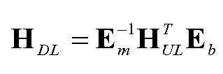
- Literature [4] provides an elementary dot-division-based resolving method, where it is modeled based on a supposition that all transceiver responses are pandiagonal (for example, hul,ij = 0, hdl,ij = 0, i ≠ j). Since any complex reciprocity error c resided in a plurality of calibrated channels would not impact the antenna array gain, the equation
- Let

respectively represent the estimated downlink and uplink channel responses H DL and H UL with erroneous coefficient square matrix A l , A r , B l, B r and complex additive white Gaussian noises N DL and N UL. Assume A l , A r , B l, B r are all full rank matrixes, and by applying the reciprocity model (5) into the equation (6), it is derived
- Let


- The above equation may be written as

where N E is a matrix whose elements follow independent complex Gaussian distribution with CN(0,
- In order to estimate the right multiplication matrix E r or left multiplication matrix E l , the following suppositions have to be introduced:
- Supposition 3): the antenna coupling effect is sufficiently small and thus may be ignored. For example, H br, H bt, H mr , H mt are all diagonal and thus E b and E m are both diagonal.
- Supposition 4): there is no matrix coefficient type of channel estimation errors, all estimation errors are of noise type, for example, A l ,A r ,B l ,B r are all identity matrixes.
- Utilizing supposition (3), by selecting a reciprocity reference, i.e., the reciprocity error em,1 of the first antenna branch of the UE, E m (identical to the estimation of E l with supposition (4)) may be first estimated through the elementary least square ELS (literature [4]) estimation algorithm , to eliminate the association between E m and E b.

where
where diag[] represents diagonal transformation. - By applying equation (8) to equation (7) and moving Ê l to the right, it may be derived

- Now, in order to obtain better performance, E b (identical to the estimation of E r with supposition 4)) may be estimated by utilizing the matrix least square (MLS) estimation algorithm, the matrix minimum mean square error (MMSE) estimation algorithm or other variants thereof.
- The advantage of the MMSE-based estimation algorithm over the ELS algorithm adopted in literature [4] lies in that it does not need the establishment of supposition (3), and thus it will better conform to the actual conditions, thereby capable of providing a better reciprocity error calibration performance.
- Hereinafter, only the embodiments of typical matrix LS and matrix MMSE estimation algorithms are illustrated. According to different design requirements (trade-off between complexity and performance), other variants may be implemented by referencing to [J. Proakis, "Digital Communications," McGraw-Hill Science, 4 edition, August 15, 2000].
- The matrix least square LS estimation method:

where (●)+ indicates the left inversion of a matrix. - The matrix MMSE estimation method:

where


r Er can be calculated from previous estimations of Ê r. - In order to better understand the present invention, the reciprocity error calibration method according to the preferred embodiments of the present invention will be described with reference to
Fig. 4 in the following. -
Fig. 4 illustrates a flow chart of a reciprocity error calibration method according to the embodiments of the present invention. - First, in step S101, the UE measures downlink channel response H DL from all of its antennas and feeds the measured H DL to eNB. For example, the measured H DL may be fed back to eNB through the channel state information (CSI).
- In step S102, the eNB measures the uplink channel response H UL based on the uplink reference signal (sounding reference signal, SRS).
- In step S103, the eNB calculates one of a user equipment reciprocity error E m and a base station reciprocity error E b based on the H DL and the H UL utilizing an algorithm adopting LS criterion in accordance with a reciprocity model

- In step S104, the eNB utilizes another algorithm adopting the MMSE criterion to calculate the other one of E m and E b based on the calculated one of the E m and E b . For example, as above mentioned, the eNB calculates the base station reciprocity error E b utilizing the matrix LS algorithm or the matrix MMSE algorithm based on the calculated user equipment reciprocity error E m .
- Finally, in step S105, the eNB performs the reciprocity error calibration operation based on the calculated user equipment reciprocity error E m and base station reciprocity error E b .
- Specifically, in step S105, as above mentioned, the equation

-
Fig. 5 illustrates a block diagram of a reciprocity error calibration device according to the embodiments of the present invention. - As illustrated in
Fig. 5 , the reciprocity error calibration device according to the embodiments of the present invention comprises: adownlink measurement module 101 configured to obtain downlink channel response H DL through measurement; anuplink measurement module 102 configured to obtain uplink channel response H UL through measurement; anLS calculation module 103 configured to calculate one of a user equipment reciprocity error E m and a base station reciprocity error E b based on the H DL and H UL utilizing an algorithm adopting LS criterion in accordance with
MMSE calculation module 104 configured to calculate the other one of the E m and E b utilizing another algorithm adopting MMSE criterion based on the calculated one of the E m and E b ; and a reciprocityerror calibration module 104 configured to perform a reciprocity calibration operation utilizing the calculated reciprocity errors E m and E b . - The reciprocity error calibration method and reciprocity error calibration device according to the embodiments of the present invention as described with reference to
Fig. 4 andFig. 5 are illustrated to be implemented at the eNB. However, those skilled in the art would appreciate that the present invention is not limited thereto. The reciprocity error calibration method and reciprocity error calibration device according to the embodiments of the present invention may also be implemented at the UE. For example, thedownlink measurement module 101 may be disposed at the UE. In this case, the reciprocity error calibration device according to the embodiments of the present invention further comprises a transmitting module disposed at the UE, configured to transmit to the eNB the downlink channel responses H DL measured by the UE from all of its antennas; and a receiving module disposed at the eNB, configured to receive the downlink channel response H DL from the UE. - Hereinafter, the proposed method will be verified through simulation. The parameters as adopted by the simulation are specified below: LTA-A link, 3 UEs, 3eNBs, each UE equipped with two antennas, each eNB equipped with 4 antennas, 16QAM, Turbo code, 1mps speed, Urban micro cell scenario, -5dB inter-cell interference, 6-bit channel quantization for feedback.
-
Fig. 6 illustrates simulation results from comparing the reciprocity error calibration method according to the embodiments of the present invention and the conventional reciprocity error calibration method. - In order to obtain the results quickly and reliably, the Signal to Interference plus Noise Ratio (SINR) of a demodulator input signals is utilized as a performance metric. By looking up the input/output SNR mapping table of the 16QAM+Turbo code, the metric may be mapped to BER/BLER.
- In
Fig. 6 , "SRS w/o RE" indicates a channel measurement result without reciprocity error; "ELS eNB + UE Cal" indicates a channel measurement result of performing the reciprocity error calibration to both the base station and the terminal utilizing the ELS estimation algorithm; "LS eNB Cal" indicates the channel measurement result of merely performing LS reciprocity error calibration to eNB; "RE w/o Cal" indicates the channel measurement result without applying any reciprocity error calibration; "MLS eNB + UE Cal" indicates the channel measurement result of performing reciprocity error calibration to both the base station and the terminal utilizing the MLS estimation algorithm; "MMSE eNB+UE Cal" indicates the channel estimation result of performing the reciprocity error calibration to both the base station and the terminal utilizing the MMSE estimation algorithm. - It is seen from
Fig. 6 that the MMSE estimation algorithm at the eNB side may realize almost perfect performance, particularly in the working SNR scope (0dB-20dB). The matrix LS (MLS) estimation algorithm may also provide a greater gain at low SNR. For SNR=0dB through the MMSE calibration algorithm of the present invention, a link gain of about 2dB may be realized. - It should be noted that iterative estimation on the UE side reciprocity error and the eNB side reciprocity error may be performed based on the aforementioned model. For example, the ELS estimation algorithm may be used to estimate E m , and then the MMSE estimation algorithm is used to estimate E b , and next, E m is updated using the matrix MMSE estimation algorithm. The process may also be started from the ELS estimation algorithm of E b , i.e., using the ELS estimation algorithm to estimate E b , and then using the MMSE estimation algorithm to estimate E m , and next, using the matrix MMSE estimation algorithm to update E b .
- The present invention provides a UE/eNB reciprocity calibration solution for TDD systems, which is applicable to a single cell or CoMP scenario, such that the performance of channel reciprocity-based TDD systems is improved, particularly in a normally working SNR range.
- Although the functions implemented by the base station according to the embodiments of the present invention are described in the form of method steps, each step as illustrated in
Fig. 4 may be implemented by one or more functional modules as illustrated inFig. 5 . The functional modules may also be integrated into one chip or one device in actual application. A person of normal skill in the art should understand that the base station in the embodiments of the present invention may also include any units or modules for other purposes. - A person of skill in the art would readily recognize that steps of various above described methods may be performed by programmed computers. Herein, some embodiments are also intended to cover machine or computer readable program storage devices, e.g., digital data storage media, and encoded machine executable or computer executable programs of instructions, wherein said instructions perform some or all of the steps of said above described methods. The program storage devices may be, e.g., digital storage, magnetic storage media such as magnetic disks and magnetic tapes, hard drives, or optically readable digital data storage media. The embodiments are also intended to cover computers programmed to execute programs recorded on storage media to perform said steps of the above described methods.
- The above description and figures merely illustrate the principle of the present invention. It will thus be appreciated that those skilled in the art will be able to devise various arrangements that, although not explicitly described or shown herein, embody the principles of the invention and are included within its spirit and scope. Furthermore, all examples recited herein are principally intended expressly to be only for pedagogical purposes to aid the reader in understanding the principles of the invention and the concepts contributed by the inventors to furthering the art, and are to be construed as being without limitation to such specifically recited examples and conditions. Moreover, all statements herein reciting principles, aspects, and embodiments of the invention, as well as specific examples thereof, are intended to encompass equivalents thereof.
Claims (12)
- A method for reciprocity error calibration, comprising steps of:measuring downlink channel response H DL ;measuring uplink channel response H UL;calculating one of a user equipment reciprocity error E m and a base station reciprocity error E b utilizing least square LS criterion based on the H DL and H UL in accordance with a reciprocity model
 calculating the other one of the E m and E b based on the calculated one of E m and E b utilizing an algorithm adopting minimum mean square error MMSE criterion; andperforming a reciprocity error calibration operation utilizing the calculated user equipment reciprocity error E m and base station reciprocity error E b .
 - The method according to claim 1, wherein the algorithm adopting LS criterion is an elementary least square ELS algorithm.
- The method according to claim 1, wherein the algorithm adopting MMSE criterion is one of a matrix least square MLS algorithm and a matrix MMSE algorithm.
- The method according to any one of claims 1-3, further comprising a step of:updating the one of the E m and E b based on

- The method according to claim 4, wherein the further algorithm adopting MMSE criterion is one of a matrix least square MLS algorithm and a matrix MMSE algorithm.
- The method according to any one of claims 1-3, wherein the method is performed at a user equipment or a base station.
- A device for reciprocity error calibration, comprising:a downlink measurement module configured to measure downlink channel response H DL ;an uplink measurement module configured to measure uplink channel response H UL ;an LS calculation module configured to calculate one of a user equipment reciprocity error E m and a base station reciprocity error E b utilizing least square LS criterionbased on the H DL and H UL in accordance with a reciprocity model
 an MMSE calculation module configured to calculate the other one of the E m and E b based on the calculated one of the E m and E b utilizing an algorithm adopting minimum mean square error MMSE criterion; anda reciprocity error calibration module configured to perform a reciprocity error calibration operation utilizing the calculated user equipment reciprocity error E m and base station reciprocity error E b .
 - The device according to claim 7, wherein the algorithm adopting LS criterion is an elementary least square ELS algorithm.
- The device according to claim 7, wherein the algorithm adopting MMSE criterion is one of a matrix least square MLS algorithm and a matrix MMSE algorithm.
- The device according to any one of claims 7-9, further comprising:an updating module configured to update the one of the E m and E b based on

- The device according to claim 10, wherein the further algorithm adopting MMSE criterion is one of a matrix least square MLS algorithm and a matrix MMSE algorithm.
- The device according to any one of claims 7-9, wherein the device is implemented at a user equipment or a base station.
Applications Claiming Priority (2)
| Application Number | Priority Date | Filing Date | Title |
|---|---|---|---|
| CN201010115749 | 2010-02-12 | ||
| PCT/CN2010/001595 WO2011097785A1 (en) | 2010-02-12 | 2010-10-12 | Device and method for calibrating reciprocity errors |
Publications (2)
| Publication Number | Publication Date |
|---|---|
| EP2536036A1 true EP2536036A1 (en) | 2012-12-19 |
| EP2536036A4 EP2536036A4 (en) | 2015-07-08 |
Family
ID=44367138
Family Applications (1)
| Application Number | Title | Priority Date | Filing Date |
|---|---|---|---|
| EP10845459.6A Withdrawn EP2536036A4 (en) | 2010-02-12 | 2010-10-12 | DEVICE AND METHOD FOR CALIBRATION OF RECIPROCITY ERRORS |
Country Status (7)
| Country | Link |
|---|---|
| US (1) | US20120314563A1 (en) |
| EP (1) | EP2536036A4 (en) |
| JP (1) | JP5384754B2 (en) |
| KR (1) | KR101393456B1 (en) |
| CN (1) | CN102714525B (en) |
| BR (1) | BR112012020140A2 (en) |
| WO (1) | WO2011097785A1 (en) |
Cited By (1)
| Publication number | Priority date | Publication date | Assignee | Title |
|---|---|---|---|---|
| CN108418770A (en) * | 2018-01-22 | 2018-08-17 | 南京邮电大学 | Frequency Domain Channel Reciprocity Compensation Method Based on Channel Estimation Error in Massive MIMO |
Families Citing this family (10)
| Publication number | Priority date | Publication date | Assignee | Title |
|---|---|---|---|---|
| KR101740371B1 (en) | 2010-11-22 | 2017-06-08 | 삼성전자 주식회사 | Device and method for allocating a antenna in cellular mobile communication system |
| CN104168071B (en) * | 2013-05-17 | 2016-09-07 | 华为技术有限公司 | The method and system of reciprocity calibration between a kind of RRU |
| JP6401256B2 (en) * | 2013-06-20 | 2018-10-10 | 株式会社Nttドコモ | Method and apparatus for relative transceiver calibration for wireless communication systems |
| US9590708B1 (en) * | 2015-08-25 | 2017-03-07 | Motorola Mobility Llc | Method and apparatus for equal energy codebooks for antenna arrays with mutual coupling |
| WO2018014967A1 (en) * | 2016-07-22 | 2018-01-25 | Huawei Technologies Duesseldorf Gmbh | Method for obtaining uplink calibration values, calibration method, and corresponding terminal and base station |
| US9991938B2 (en) * | 2016-08-11 | 2018-06-05 | National Instruments Corporation | Intra-node channel reciprocity compensation for radio access in MIMO wireless communication systems |
| US10033558B2 (en) | 2016-10-04 | 2018-07-24 | Qualcomm Incorporated | Inter-eNB over-the-air calibration for reciprocity-based coordinated multipoint communications |
| CN115529607B (en) * | 2021-06-25 | 2024-10-11 | 华为技术有限公司 | A channel reciprocity calibration method, device and system |
| US12506524B2 (en) * | 2021-09-02 | 2025-12-23 | Samsung Electronics Co., Ltd. | System and method for user equipment assisted over-the-air calibration |
| WO2025110031A1 (en) * | 2023-11-21 | 2025-05-30 | 京セラ株式会社 | Electronic device, control method, and program |
Family Cites Families (12)
| Publication number | Priority date | Publication date | Assignee | Title |
|---|---|---|---|---|
| US6684061B1 (en) * | 2000-07-20 | 2004-01-27 | Telefonaktiebolaget Lm Ericsson (Publ) | Systems and methods for measuring interference reciprocity between uplink and downlink directions in a wireless communications system |
| US8134976B2 (en) * | 2002-10-25 | 2012-03-13 | Qualcomm Incorporated | Channel calibration for a time division duplexed communication system |
| US8570988B2 (en) | 2002-10-25 | 2013-10-29 | Qualcomm Incorporated | Channel calibration for a time division duplexed communication system |
| US7236535B2 (en) * | 2002-11-19 | 2007-06-26 | Qualcomm Incorporated | Reduced complexity channel estimation for wireless communication systems |
| JP4361938B2 (en) * | 2003-12-30 | 2009-11-11 | テレフオンアクチーボラゲット エル エム エリクソン(パブル) | Calibration method to realize reciprocity of two-way communication channel |
| US7206354B2 (en) * | 2004-02-19 | 2007-04-17 | Qualcomm Incorporated | Calibration of downlink and uplink channel responses in a wireless MIMO communication system |
| US7486740B2 (en) * | 2004-04-02 | 2009-02-03 | Qualcomm Incorporated | Calibration of transmit and receive chains in a MIMO communication system |
| US7366245B2 (en) | 2004-09-10 | 2008-04-29 | Intel Corporation | Calibration in MIMO systems |
| KR20070032548A (en) * | 2005-09-16 | 2007-03-22 | 삼성전자주식회사 | Channel Correction Device and Method in Wireless Communication System Using Multiple Antennas |
| WO2007103085A2 (en) * | 2006-03-01 | 2007-09-13 | Interdigital Technology Corporation | Method and apparatus for calibration and channel state feedback to support transmit beamforming in a mimo system |
| WO2008146494A1 (en) * | 2007-05-29 | 2008-12-04 | Mitsubishi Electric Corporation | Calibration method, communication system, frequency control method, and communication device |
| EP2448137A1 (en) * | 2009-06-23 | 2012-05-02 | Alcatel Lucent | Method and device for signal transmission in time-division duplex mimo system |
-
2010
- 2010-10-12 US US13/578,307 patent/US20120314563A1/en not_active Abandoned
- 2010-10-12 WO PCT/CN2010/001595 patent/WO2011097785A1/en not_active Ceased
- 2010-10-12 CN CN201080056361.8A patent/CN102714525B/en active Active
- 2010-10-12 KR KR1020127023595A patent/KR101393456B1/en not_active Expired - Fee Related
- 2010-10-12 JP JP2012552227A patent/JP5384754B2/en not_active Expired - Fee Related
- 2010-10-12 EP EP10845459.6A patent/EP2536036A4/en not_active Withdrawn
- 2010-10-12 BR BR112012020140-9A patent/BR112012020140A2/en not_active IP Right Cessation
Cited By (1)
| Publication number | Priority date | Publication date | Assignee | Title |
|---|---|---|---|---|
| CN108418770A (en) * | 2018-01-22 | 2018-08-17 | 南京邮电大学 | Frequency Domain Channel Reciprocity Compensation Method Based on Channel Estimation Error in Massive MIMO |
Also Published As
| Publication number | Publication date |
|---|---|
| CN102714525A (en) | 2012-10-03 |
| EP2536036A4 (en) | 2015-07-08 |
| US20120314563A1 (en) | 2012-12-13 |
| JP2013520043A (en) | 2013-05-30 |
| KR101393456B1 (en) | 2014-05-13 |
| JP5384754B2 (en) | 2014-01-08 |
| CN102714525B (en) | 2015-11-25 |
| WO2011097785A1 (en) | 2011-08-18 |
| BR112012020140A2 (en) | 2019-09-24 |
| KR20120125527A (en) | 2012-11-15 |
Similar Documents
| Publication | Publication Date | Title |
|---|---|---|
| EP2536036A1 (en) | Device and method for calibrating reciprocity errors | |
| CN114424623B (en) | Channel Estimation Based on Machine Learning | |
| US11901979B2 (en) | Channel reciprocity-based precoding matrix configuration method and apparatus | |
| JP5497966B2 (en) | Method and device for calibrating antenna correlation in a base station of a wireless network | |
| US8532214B2 (en) | MIMO channel state information estimation with coupled iterative two-stage ranking | |
| TWI580209B (en) | Method and device for gain normalization correction of pmi and cqi feedback for base station with antenna array | |
| EP3589004A1 (en) | Method of setting up reference signal in radio communication system and system therefor | |
| US9516528B2 (en) | Method for estimating interference within a serving cell, user equipment, computer program and computer program products | |
| US8818291B2 (en) | Method and device for antenna calibration | |
| CN114303407B (en) | Uplink beam management | |
| CN115175303B (en) | Positioning method, device and readable storage medium | |
| US8774066B2 (en) | Macro-femto inter-cell interference mitigation | |
| CN115298967A (en) | PIM downlink subspace acquisition method | |
| CN119678391A (en) | Method and apparatus for uplink transmission | |
| US20240072911A1 (en) | Calibration of transmit antenna chains and receive antenna chains of an antenna system | |
| WO2011097784A1 (en) | Equipment and method for reciprocity error calibration | |
| US20240259063A1 (en) | Modified Type II Control State Information Reporting | |
| US12063184B2 (en) | Codebook assisted covariance transformation in frequency division duplex (FDD) systems | |
| Liu et al. | An improved relative channel reciprocity calibration method in TDD massive MIMO systems |
Legal Events
| Date | Code | Title | Description |
|---|---|---|---|
| PUAI | Public reference made under article 153(3) epc to a published international application that has entered the european phase |
Free format text: ORIGINAL CODE: 0009012 |
|
| 17P | Request for examination filed |
Effective date: 20120912 |
|
| AK | Designated contracting states |
Kind code of ref document: A1 Designated state(s): AL AT BE BG CH CY CZ DE DK EE ES FI FR GB GR HR HU IE IS IT LI LT LU LV MC MK MT NL NO PL PT RO RS SE SI SK SM TR |
|
| DAX | Request for extension of the european patent (deleted) | ||
| 111Z | Information provided on other rights and legal means of execution |
Free format text: AL AT BE BG CH CY CZ DE DK EE ES FI FR GB GR HR HU IE IS IT LI LT LU LV MC MK MT NL NO PL PT RO RS SE SI SK SM TR Effective date: 20130410 |
|
| RAP1 | Party data changed (applicant data changed or rights of an application transferred) |
Owner name: ALCATEL LUCENT |
|
| D11X | Information provided on other rights and legal means of execution (deleted) | ||
| RA4 | Supplementary search report drawn up and despatched (corrected) |
Effective date: 20150609 |
|
| RIC1 | Information provided on ipc code assigned before grant |
Ipc: H04B 17/00 20150101AFI20150602BHEP |
|
| STAA | Information on the status of an ep patent application or granted ep patent |
Free format text: STATUS: THE APPLICATION IS DEEMED TO BE WITHDRAWN |
|
| 18D | Application deemed to be withdrawn |
Effective date: 20160108 |