EP2536001A1 - Power supply device - Google Patents
Power supply device Download PDFInfo
- Publication number
- EP2536001A1 EP2536001A1 EP11739778A EP11739778A EP2536001A1 EP 2536001 A1 EP2536001 A1 EP 2536001A1 EP 11739778 A EP11739778 A EP 11739778A EP 11739778 A EP11739778 A EP 11739778A EP 2536001 A1 EP2536001 A1 EP 2536001A1
- Authority
- EP
- European Patent Office
- Prior art keywords
- battery
- power source
- equalizing
- parallel
- switch
- Prior art date
- Legal status (The legal status is an assumption and is not a legal conclusion. Google has not performed a legal analysis and makes no representation as to the accuracy of the status listed.)
- Withdrawn
Links
Images




Classifications
-
- H—ELECTRICITY
- H02—GENERATION; CONVERSION OR DISTRIBUTION OF ELECTRIC POWER
- H02J—ELECTRIC POWER NETWORKS; CIRCUIT ARRANGEMENTS OR SYSTEMS FOR SUPPLYING OR DISTRIBUTING ELECTRIC POWER; SYSTEMS FOR STORING ELECTRIC ENERGY
- H02J7/00—Circuit arrangements for charging or discharging batteries or for supplying loads from batteries
- H02J7/50—Circuit arrangements for charging or discharging batteries or for supplying loads from batteries acting upon multiple batteries simultaneously or sequentially
- H02J7/52—Circuit arrangements for charging or discharging batteries or for supplying loads from batteries acting upon multiple batteries simultaneously or sequentially for charge balancing, e.g. equalisation of charge between batteries
- H02J7/54—Passive balancing, e.g. using resistors or parallel MOSFETs
-
- H—ELECTRICITY
- H01—ELECTRIC ELEMENTS
- H01M—PROCESSES OR MEANS, e.g. BATTERIES, FOR THE DIRECT CONVERSION OF CHEMICAL ENERGY INTO ELECTRICAL ENERGY
- H01M10/00—Secondary cells; Manufacture thereof
- H01M10/42—Methods or arrangements for servicing or maintenance of secondary cells or secondary half-cells
- H01M10/425—Structural combination with electronic components, e.g. electronic circuits integrated to the outside of the casing
-
- H—ELECTRICITY
- H01—ELECTRIC ELEMENTS
- H01M—PROCESSES OR MEANS, e.g. BATTERIES, FOR THE DIRECT CONVERSION OF CHEMICAL ENERGY INTO ELECTRICAL ENERGY
- H01M10/00—Secondary cells; Manufacture thereof
- H01M10/42—Methods or arrangements for servicing or maintenance of secondary cells or secondary half-cells
- H01M10/44—Methods for charging or discharging
- H01M10/441—Methods for charging or discharging for several batteries or cells simultaneously or sequentially
-
- H—ELECTRICITY
- H01—ELECTRIC ELEMENTS
- H01M—PROCESSES OR MEANS, e.g. BATTERIES, FOR THE DIRECT CONVERSION OF CHEMICAL ENERGY INTO ELECTRICAL ENERGY
- H01M10/00—Secondary cells; Manufacture thereof
- H01M10/42—Methods or arrangements for servicing or maintenance of secondary cells or secondary half-cells
- H01M10/46—Accumulators structurally combined with charging apparatus
- H01M10/465—Accumulators structurally combined with charging apparatus with solar battery as charging system
-
- Y—GENERAL TAGGING OF NEW TECHNOLOGICAL DEVELOPMENTS; GENERAL TAGGING OF CROSS-SECTIONAL TECHNOLOGIES SPANNING OVER SEVERAL SECTIONS OF THE IPC; TECHNICAL SUBJECTS COVERED BY FORMER USPC CROSS-REFERENCE ART COLLECTIONS [XRACs] AND DIGESTS
- Y02—TECHNOLOGIES OR APPLICATIONS FOR MITIGATION OR ADAPTATION AGAINST CLIMATE CHANGE
- Y02E—REDUCTION OF GREENHOUSE GAS [GHG] EMISSIONS, RELATED TO ENERGY GENERATION, TRANSMISSION OR DISTRIBUTION
- Y02E60/00—Enabling technologies; Technologies with a potential or indirect contribution to GHG emissions mitigation
- Y02E60/10—Energy storage using batteries
Definitions
- the present invention relates to a power source apparatus provided with a high capacity array of batteries to obtain both high output voltage and high output current.
- a power source apparatus with both high output voltage and high output current has many batteries (or battery cells) connected in series to increase the output voltage.
- the series-connected batteries are charged by the same current and discharged by the same current. Accordingly, if all the batteries have exactly the same characteristics, no imbalance (between batteries) will develop in battery voltage or remaining charge capacity.
- batteries cannot be manufactured with exactly the same characteristics. With the repetition of charge-discharge cycles, battery voltage and/or remaining charge capacity imbalance will develop between batteries. Further, battery voltage imbalance can cause over-charging or over-discharging of a specific battery (a battery with low capacity or high internal resistance). To avoid these detrimental effects, a vehicle power source apparatus has been developed with cell balancing capability that detects the voltage of each battery and eliminates imbalance between battery cells.
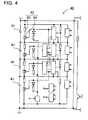
- the vehicle power source apparatus 40 cited in JP 2006-149068 has a discharge circuit 42 connected in parallel with each battery 41 in the series-connected battery array.
- Each discharge circuit 42 is a series-connection of a discharge resistor 43 and a switching device 44.
- a battery 41 that has become high in voltage is discharged through its discharge circuit 42 to restore cell balance and eliminate disparity between batteries 41.
- a discharge circuit 42 lowers the voltage of a specific battery 41 by switching the switching device 44 ON to discharge the battery 41 through the discharge resistor 43.
- This power source apparatus 40 can eliminate imbalance between the series-connected batteries 41.
- high output voltage can be attained by connecting many batteries in series, but the current capacity is that of the individual batteries. Since the power output of a power source apparatus is proportional to the product of voltage and current, increasing the current can further increase the power output. Specifically, by connecting many batteries in series and parallel, both the output current and output voltage can be increased to further increase the power output of the power source apparatus.
- voltages of the series-connected batteries can be equalized to eliminate imbalance in the same manner cited in JP 2006-149068 .
- the present invention was developed considering the types of prior art problems described above. Thus, it is a primary object of the present invention to provide a power source apparatus that can efficiently equalize the battery cells while connecting many cells in series and parallel.
- the power source apparatus of the present invention connects a plurality of battery cells in parallel with a configuration having a plurality of battery cells connected in parallel as battery packs, a plurality of battery packs connected in series as battery units, and a plurality of battery units connected in parallel to an output line.
- the power source apparatus can be provided with first equalizing circuits to control remaining capacity variation between the plurality of battery units, and second equalizing circuits to control remaining capacity variation between all the series-connected battery packs that make up each battery unit.
- This configuration eliminates non-uniformity between battery units with the first equalizing circuits, and eliminates non-uniformity between the battery packs included in each battery unit with the second equalizing circuits to maintain cell balance between the many battery cells included in the power source apparatus.
- Cell balancing is not performed on a cell by cell basis, but rather on a block by block basis achieving the positive feature that cell balance can be restored rapidly and efficiently.
- a second equalizing circuit 24 can be connected in parallel with each battery pack 20, and can be provided with a second series circuit configured with a second (current) limiting resistor 25 and a second equalizing switch 26. This allows non-uniformity between the battery packs in each battery unit to be eliminated via the second equalizing circuits.
- connections between the battery packs 20 in each battery unit 10 can be made with detachable connectors. This allows easy connection and replacement of battery packs. In particular, when a battery pack malfunctions, it can be easily replaced to shorten apparatus down-time, and since all the battery packs do not need to be replaced, the positive feature of cost reduction is achieved.
- each battery pack 20 can be configured with a plurality of parallel blocks connected in series, and each parallel block can have a plurality of battery cells 31 connected in parallel. Further, a third equalizing circuit 34 can be provided with each parallel block to equalize the plurality of parallel blocks in each battery pack 20. This allows non-uniformity among the plurality of parallel blocks included in a battery pack to also be eliminated.
- the array of batteries can have a capacity of 1 KVA to 100 KVA.
- battery units 10 can be connected to the output line OL in a detachable manner.
- the power source apparatus for the seventh aspect of the present invention can be provided with a power source controller 2 to control parallel connecting switches 12 and equalizing switches.
- the power source controller 2 can turn a parallel connecting switch 12 ON to connect a battery unit 10 in parallel, and can turn the parallel connecting switch 12 OFF and the equalizing switch ON to equalize the battery unit 10.
- this (active cell balancing) method has the positive feature that power can be used effectively to charge lower voltage battery units and increase their voltage, reduce the battery unit voltage difference ⁇ VU, and reduce the time required for equalization.
- battery cells 31 that make up the battery packs 20 can be lithium ion batteries.
- the power source apparatus for the ninth aspect of the present invention can be provided with a switch control circuit 6 connected in parallel with the first equalizing circuits 14 and parallel connecting switches 12 to control the parallel connecting switches 12 and first equalizing switches 16.
- the switch control circuit 6 can turn the first equalizing switch 16 in the first equalizing circuit 14 ON to connect the battery unit 10 to the load LD and limit surge current with a first (current) limiting resistor 15.
- the switch control circuit 6 can turn the parallel connecting switch 12 ON to connect the battery unit 10 to the load LD. This can prevent surge current in the load by using the first equalizing circuits for the dual purpose of surge current suppression instead of providing a special-purpose circuit to prevent surge current in the load.
- components with the same name and label indicate components that are the same or have the same properties and their detailed description is appropriately abbreviated.
- a single component can serve multiple functions and a plurality of structural elements of the invention can be implemented with the same component.
- the functions of a single component can be divided among a plurality of components.
- explanations used to describe part of one embodiment may be used in other embodiments and descriptions.
- Figs. 1-3 show the power source apparatus 100 for the first embodiment of the present invention.
- Fig. 1 is a block diagram of the power source system using the power source apparatus 100
- Fig. 2 is a block diagram showing the battery units 10 in Fig. 1 during equalization
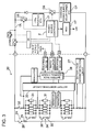
- Fig. 3 is a block diagram of one of the battery packs 20 that make up a battery unit 10 in Fig. 1 .
- the power source system shown in these figures is provided with a power source apparatus 100, a load LD, and a charging power supply CP. After being charged by the charging power supply CP, the power source apparatus 100 drives the load LD.
- the power source apparatus 100 has a charging mode, a discharging mode, and an equalizing mode to equalize the battery units 10 (described later).
- the load LD and the charging power supply CP are connected to the power source apparatus 100 through a discharge switch DS and a charging switch CS respectively.
- the discharge switch DS and the charging switch CS are controlled ON and OFF by the power source apparatus 100 power source controller 2.
- the power source controller 2 switches the charging switch CS ON and the discharge switch DS OFF to allow the power source apparatus 100 to be charged from the charging power supply CP.
- the power source apparatus 100 can be switched to the discharging mode depending on demand by the load LD.
- the power source controller 2 switches the charging switch CS OFF and the discharge switch DS ON to allow discharge from the power source apparatus 100 to the load LD. Further, depending on requirements, both the charging switch CS and the discharge switch DS can be turned ON to allow power to be simultaneously supplied to the load LD while charging the power source apparatus 100.
- the load LD driven by the power source apparatus 100 is connected to the power source apparatus 100 through the discharge switch DS.
- the power source controller 2 switches the discharge switch DS ON to connect and drive the load LD with power from the power source apparatus 100.
- a switching device such as a field effect transistor (FET) can be used as the discharge switch DS.
- FET field effect transistor
- the discharge switch DS is controlled ON and OFF by the power source apparatus 100 power source controller 2.
- the charging power supply CP is connected in series with the charging switch CS.
- the charging switch CS is turned ON to charge the power source apparatus 100 with the charging power supply CP. Further, when full-charge of the power source apparatus 100 is detected, the charging switch CS is switched OFF. These switching operations are performed by the power source controller 2.
- Power generating systems including those that utilize renewable energy sources such as solar, wind, tidal, and geothermal; or fuel cells, gas power generators, and commercial power sources can be used as the charging power supply CP. In the example of Fig. 1 , solar panels are used as the charging power supply CP.
- a switching device such as a FET can also be used as the charging switch CS.
- the charging switch CS is also controlled ON and OFF by the power source apparatus 100 power source controller 2.
- the charging switch CS is connected between the charging power supply CP and the power source apparatus 100 to control charging of the power source apparatus 100. Charging is not performed by a technique such as voltage conversion through a direct current to direct current (DC/DC) converter, but rather pulse charging is performed using ON and OFF switching of the charging switch CS. This allows high efficiency and simplification of the circuitry.
- DC/DC direct current to direct current
- the power source apparatus 100 is provided with parallel connecting switches 12 connected to each battery unit 10, first equalizing circuits 14 to equalize the battery units 10, OR circuits 4 (logic gates) connected to the parallel connecting switches 12, the first equalizing circuits 14, and the battery units 10, and the power source controller 2 connected to the OR circuits 4.
- Each parallel connecting switch 12 connects a battery unit 10 to an output line OL to connect the battery units 10 in parallel through the parallel connecting switches 12.
- Devices such as insulated gate bipolar transistors (IGBTs) can be used as the parallel connecting switches 12.
- Each first equalizing circuit 14 is configured as a first series circuit with a first limiting resistor 15 (15A and 15B in Fig. 1 ) and a first equalizing switch 16 (16A and 16B in Fig. 1 ).
- a device such as a FET can be used as the first equalizing switch 16.
- the first equalizing switch 16 and the parallel connecting switch 12 are controlled ON and OFF in accordance with the charging mode, the discharging mode, and the equalizing mode. During normal operation in the charging mode and the discharging mode, each parallel connecting switch 12 is in the ON state and each first equalizing switch 16 is in the OFF state. However, in the equalizing mode, the applicable parallel connecting switch 12 is switched OFF and the applicable first equalizing switch 16 is switched ON.
- the power source controller 2 is connected with each battery unit 10, each OR circuit 4, the discharge switch DS, and the charging switch CS.
- the power source apparatus 100 shown in Fig. 1 has two battery units 10 connected in parallel, and is controlled by the power source controller 2 to drive the load LD and charge each battery unit 10 with the charging power supply CP.
- the power source controller 2 switches the discharge switch DS and the charging switch CS ON and OFF depending on the mode (charging mode or discharging mode).
- the power source controller 2 is connected to each battery unit 10, and switches each first equalizing switch 16 and parallel connecting switch 12 ON and OFF to perform equalization between battery units 10 in accordance with signals from the battery units 10.
- the power source controller 2 when the power source controller 2 receives a signal indicating an abnormality from a battery unit 10 via the input terminal DI of the parent battery pack 20 (described later), the power source controller 2 controls a parallel connecting switch 12 to disconnect that battery unit 10.
- the power source controller 2 can be made up of circuitry that includes a central processing unit such as a micro-processing unit (MPU).
- MPU micro-processing unit
- a power source apparatus with two battery units 10 is described.
- the battery units in this example are controlled by a single power source controller
- the power source apparatus can be configured with a plurality of power source controllers when there are a large number of battery units.
- the power source controller in the example of Fig. 1 is separate from the battery units, it can also be disposed inside the battery units.
- the capabilities of the power source controller can be included in the battery pack control circuit 39 in the parent battery pack 20 (described later).
- the power source controller 2 is provided with a communication interface to communicate with externally connected equipment.
- the power source controller 2 is connected to an external host computer HT and communicates via known protocols such as universal asynchronous receiver transmitter (UART) and recommended standard-232 (RS-232C) protocols.
- UART universal asynchronous receiver transmitter
- RS-232C recommended standard-232
- a user interface can be provided to allow direct user control of the power source system.
- an input device such as a keyboard, mouse, touch-panel, or console (terminal) can be connected as a user interface for the power source controller, and inputs can be made such as specifying the maximum current or setting the utilization of connected battery units.
- An indicator panel or warning lights can also be provided to alert the user when a battery pack 20 abnormality develops.
- the output voltage (unit voltage) of the two battery units 10A, 10B are compared by the power source controller 2 during the discharging mode.
- the battery unit voltage difference ⁇ VU is greater than or equal to a battery unit threshold voltage (such as 1V)
- the system transitions to the equalizing mode to equalize the battery units 10.
- the total voltage of the parent battery pack 20 and each child battery pack 20 (described later) is computed by the battery pack control circuit 39 in the parent battery pack, and that total is sent to the power source controller 2 as the battery unit voltage.
- the sum of the output voltages of all the battery packs 20 in each battery unit 10 can also be computed in the power source controller 2, and a voltage sensor can also be provided with each battery unit.
- each battery pack 20 has lithium ion rechargeable batteries as battery cells 31, has twenty four cells connected in parallel, and is a series-connection of thirteen of the parallel connected cells.
- This type of battery pack 20 has a specified output voltage of 50V and output current of 30A.
- equalization is described based on Fig. 2 when the voltage of battery unit 10A becomes greater than the voltage of battery unit 10B.
- the power source controller 2 turns OFF the charging switch CS and the discharge switch DS.
- the power source controller 2 turns the parallel connecting switch 12A in battery unit 10A OFF and the first equalizing switch 16A ON.
- the parallel connecting switch 12B in battery unit 10B is left in the ON state and the first equalizing switch 16B is left in the OFF state the same as in the discharging mode.
- This connects battery unit 10A with battery unit 10B through the first series circuit of battery unit 10A as shown by the arrows in Fig. 2 .
- the power source controller 2 monitors the battery unit voltage difference ⁇ VU to determine whether or not to perform battery unit equalization after completing charging of each battery unit 10 at the point of transition to the discharging mode.
- the technique described above can utilize battery unit power in an effective manner.
- the voltage of the low voltage battery unit increases due to charging to reduce the battery unit voltage difference ⁇ VU, it has the positive feature that the time required for equalization can be reduced.
- a battery unit 10 is made up of a plurality of connected battery packs 20. Each battery unit 10 is connected to the output line OL through a parallel connecting switch 12.
- battery unit 10A and battery unit 10B are the same type of battery units 10. As mentioned previously, although two battery units 10 are used in the figures, it is also possible to connect three or more battery units.
- a battery unit 10 with a plurality of battery packs 20 connected together one of the battery packs 20 functions as the parent battery pack with the other battery packs 20 serving as child battery packs controlled by the parent battery pack.
- the parent battery pack monitors the child battery packs and reports status to the power source controller 2.
- the parent battery pack and child battery packs are configured as the same type of battery pack 20. Specifically, all the battery packs 20 are made with a common structure and since a battery pack 20 can function as a parent battery pack or a child battery pack depending on the connecting configuration, manufacturing cost can be reduced.
- the battery pack 20 connected at the lower end of the battery unit 10 is used as the parent battery pack, and all the other battery packs 20 are used as child battery packs.
- Each battery pack 20 in Fig. 1 is provided with signal terminals and power terminals.
- a battery pack input terminal DI, a battery pack error output terminal DA, and a battery pack output terminal DO are provided as signal terminals for the battery pack control circuit 39.
- the battery pack input terminal DI is a terminal for inputting signals from other battery packs and the power source controller 2.
- the battery pack output terminal DO is a terminal for outputting signals to other battery packs and the power source controller 2.
- the battery pack error output terminal DA is a terminal for outputting information conveying battery pack abnormality outside the battery pack.
- battery pack error output terminals DA are connected to the OR circuits 4.
- Each battery pack 20 is also provided with a positive terminal and a negative terminal as output terminals for the battery cells 31 connected together in the battery pack 20. Positive terminals and negative terminals of adjacent battery packs 20 are connected to connect the battery packs 20 series and increase output voltage.
- each battery unit 10 in Fig. 1 includes one parent battery pack and a plurality of child battery packs.
- the parent battery pack and child battery packs are connected in a string arrangement.
- the output terminal DO of the previous battery pack 20 is connected to the input terminal DI of the next battery pack 20.
- the input terminal DI of the parent battery pack is connected with the output of the power source controller 2.
- the output terminal DO of the last child battery pack is left unconnected. Note in this type of daisy-chain connection, the output terminal DO of the last child battery pack can also be connected to a terminator such as a termination resistor to indicate the position of the end of the signal line.
- the battery pack input terminal DI, battery pack error output terminal DE, and battery pack output terminal DO connect to two signal lines for data communication with the power source controller 2.
- Data communication can be via a method such as packet communication that designates the destination of transmission.
- each battery pack has a preassigned unique identifier (address), and packets for packet communication include the address of the destination battery pack and commands issued to that battery pack. This allows data communication targeted to individual battery packs over a common signal line.
- Methods of assigning a unique address to each battery pack are applied as appropriate and include automatic allocation by the power source controller depending on the battery pack connecting scheme, and manual setting of switches such as dual inline package (DIP) switches in each battery pack.
- DIP dual inline package
- addresses can be set when the user presses a specially provided address setting switch, or when connection of a child battery pack is detected automatically by the parent battery pack.
- address setting can be performed when the terminator is connected.
- a detection device such as a micro-switch or shorting pin can be disposed in the connecting region of the of the battery pack output terminal DO, and when the terminator is connected, the micro-switch physically closes or the detection signal line short circuits to automatically activate address allocation. In this case, it is desirable to establish a detection signal line separate from the power line and other signal lines.
- the child battery pack with the terminator connected obtains its address, and subsequently a signal is sent to allocate the address of the next connected child battery pack.
- address allocation signals are successively issued to the child battery packs in their connection order.
- the parent battery pack receives an address, the fact that addresses have been allocated to all the battery packs is recognized, and the address allocation process is ended.
- the parent battery pack can acquire battery data (such as battery voltage, temperature, and error data) from each child battery pack using a communication protocol (for example, a protocol that uses a master-slave relation) such as RS-485.
- a communication protocol for example, a protocol that uses a master-slave relation
- Various data signals can be communicated from the parent battery pack to the power source controller 2 via a communication protocol such as RS-485.
- each battery unit 10 has one parent battery pack and four child battery packs connected for a total of five battery packs 20 in each battery unit 10 (in the figure, each battery unit is shown as a column of three battery packs with two battery packs not shown).
- Signal line connection between battery packs 20 is made by detachable connectors. This allows battery packs 20 to be easily connected and disconnected, which is advantageous during maintenance operations.
- Each battery pack error output terminal DA is connected to an OR circuit 4.
- An OR circuit 4 is provided with each battery unit 10. Accordingly, in each battery unit 10, one parent battery pack and four child battery packs are connected to the OR circuit 4. If a stop-signal (error signal) is output to the OR circuit 4 from any one of the battery packs, the parallel connecting switch 12 is opened to disconnect that battery pack (and its associated battery unit) from the power source apparatus. In this manner, even if a battery pack malfunction develops, all other battery packs can be protected by disconnecting the affected battery pack (and its associated battery unit). Malfunctions include abnormal conditions such as over-charging and over-discharging.
- the power source controller 2 receives signals indicating the error condition and notifies the user urging replacement of the affected battery pack. Power source system recovery can be achieved by the user replacing only the affected battery pack. This system architecture can reduce repair cost by making it possible to replace only the affected battery pack, and since battery pack replacement is made simple by the use of detachable connectors, maintainability is improved.
- the OR circuits 4 are connected with the power source controller 2 through a common bus line.
- the OR circuit 4 provided with each battery unit 10 is connected to the parallel connecting switch 12 and to the power source controller 2.
- the power source controller 2 turns the parallel connecting switch 12 OFF and notifies the user for battery pack 20 replacement when it receives an error signal from the battery pack control circuit 39 in a battery unit 10.
- the power source controller 2 can urge battery pack replacement by sending that information from its communication interface to externally connected equipment.
- the power source controller 2 can convey the need for battery pack replacement to the user by display on an indicator panel or by illumination of warning lights.
- system architecture is not limited to that of the example shown in Fig. 1 .
- Each battery pack 20 is provided with a second equalizing circuit 24 configured as a second series circuit having a second limiting resistor 25 and a second equalizing switch 26.
- a second series circuit is connected in parallel with each battery pack 20, and those second equalizing circuits 24 operate to eliminate non-uniformity among the battery packs 20.
- the second equalizing circuits 24 operate to equalize battery pack 20 voltages to eliminate imbalance.
- a battery pack 20 with high voltage is discharged through the second limiting resistor 25 of the second equalizing circuit 24.
- the present invention does not limit the equalizing circuits to circuitry that discharges batteries through current limiting resistors (passive cell balancing).
- an equalizing circuit could discharge a high voltage battery into a charge storage device such as a capacitor or another battery, and transfer that accumulated charge by discharging the charge storage device to a low voltage battery to eliminate voltage differences between batteries (active cell balancing).
- the second equalizing circuit 24 shown in Fig. 3 has the second limiting resistor 25 and second equalizing switch 26 connected in series as the second series circuit.
- the power source controller 2 or the battery pack control circuit 39 detects the voltages of each battery pack 20 and equalizes the battery packs 20 in a battery unit 10 by controlling the second equalizing switches 26 ON and OFF.
- a second series circuit having a second limiting resistor 25 and second equalizing switch 26 is connected in parallel with each battery pack 20. When the voltage of a battery pack 20 becomes high, the second equalizing switch 26 of the second equalizing circuit 24 is switched ON by the battery pack control circuit 39, and the battery pack 20 is discharged through the second limiting resistor 25 to reduce and equalize battery pack 20 voltage.
- Battery pack control circuits 39 provided with micro-processors compare battery pack 20 voltages, and control the second equalizing switches 26 to equalize the voltages of all the battery packs 20.
- the battery pack control circuit 39 switches ON the second equalizing switch 26 in the second series circuit connected with that battery pack 20.
- the second equalizing switch 26 is turned OFF.
- Fig. 3 shows a block diagram of one of the battery packs 20 included in a battery unit 10.
- This battery pack 20 is connected as a parent battery pack in the example of Fig. 1 .
- the battery pack 20 is provided with an assembly of battery cells 31 having a plurality of cells connected in series and parallel, a current fuse connected in series with the assembly of battery cells 31, a battery monitoring circuit 33, a battery pack current detection circuit 37, and a battery pack control circuit 39 primarily made up of a micro-processor with the capability to judge cell balance.
- the battery pack 20 is housed in a battery pack case.
- a standard 19-inch rack-mount case such as that used in server computer back-up power supplies can be used as the battery pack case. This can improve versatility by utilizing a commonly available chassis such as a server rack.
- the current fuse physically opens the circuit in an over-current situation to protect the battery pack 20.
- the battery monitoring circuit 33 detects the voltage of each block of parallel-connected battery cells 31 and sends that data to the battery pack control circuit 39.
- the battery pack control circuit 39 detects battery pack 20 over-charging in the charging mode and protects the battery cells 31 from over-charging by limiting the charging current.
- the battery pack control circuit 39 detects battery pack 20 over-discharging and protects the battery cells 31 from over-discharging by limiting the discharge current.
- the battery pack input terminal DI and battery pack output terminal DO are connected to the battery pack control circuit 39 via isolation devices.
- the battery pack error output terminal DA is connected to the battery pack control circuit 39 via a photo-coupler (optical isolation device). This isolates each signal terminal with respect to external connection.
- the number of connected battery packs 20 can be adjusted to easily meet the requirements of large-scale applications. Further, even if malfunction occurs in a battery cell, only the battery pack that includes that battery cell needs to be isolated from the system and replaced. This has the positive feature that replacement costs can be reduced.
- the battery pack current detection circuit 37 detects charging and discharging current and sends that data to the battery pack control circuit 39.
- the battery pack current detection circuit 37 can detect battery pack current from the voltage across a current detection resistor connected in series with the battery pack 30.
- Temperature sensors that detect battery cell 31 temperature and voltage sensors that detect the voltage of each block of parallel-connected battery cells 31 are connected to the battery monitoring circuit 33.
- Thermistors can be used as the temperature sensors.
- the battery monitoring circuit 33 detects over-charging or over-discharging based on battery cell 31 temperature and battery cell 31 or parallel block voltage. If over-charging or over-discharging is detected, a signal is output to the OR circuit 4 from the battery pack error output terminal DA to open the parallel connecting switch 12 and disconnect the battery unit containing the affected battery pack. As described below, this capability is employed when error detection by the battery pack control circuit 39 does not function properly.
- Data such as battery voltage values converted by analog to digital (A/D) conversion are output from the battery monitoring circuit 33 to the battery pack control circuit 39. Based on battery voltage values, conditions such as over-charging and over-discharging are judged in the battery pack control circuit 39. In the event of an error condition such as over-charging or over-discharging, error data is transmitted from the child battery packs to the parent battery pack. In addition, values such as battery voltage for each battery pack are transmitted as data from the child battery packs to the parent battery pack.
- the battery pack control circuit 39 of the parent battery pack communicates that to the power source controller 2. In that situation, the power source controller 2 turns the parallel connecting switch 12 (for that battery unit 10) OFF via the OR circuit 4.
- the battery pack control circuit 39 in the parent battery pack also acquires the battery voltages of the child battery packs and the parent battery pack, adds those voltages to obtain a total value, and transmits that total to the power source controller 2.
- Each battery pack 20 has parallel blocks with a plurality of battery cells 31 connected in parallel, and a plurality of parallel blocks are in turn connected in series. However, it is also possible for a battery pack to have no series-connected battery cells and only parallel-connected battery cells. In the example of Fig. 3 , since the assembly of batteries is made up of parallel blocks with twenty four parallel-connected battery cells 31 and thirteen parallel blocks in turn connected in series, a total of 312 battery cells 31 are used in the battery pack 20. This battery pack 20 is used with a specified voltage of 50V and a specified current of 30A. Since a battery unit 10 shown in Fig.
- each battery unit 10 uses a total of 1560 battery cells 31 to achieve a specified voltage of 250V and a specified current of 30A. Further, by connecting a plurality of these battery units in parallel, a high reliability power source apparatus is formed.
- the total number of batteries used sets the capacity of the array of batteries depending on the application. For example, capacity can be 1 KVA to 100 KVA.
- battery cells 31 that have rectangular outer cases can be used as the battery cells 31.
- Rechargeable batteries such as lithium ion rechargeable batteries, nickel hydride batteries, and nickel cadmium batteries are appropriate for use as battery cells 31.
- the use of lithium ion rechargeable batteries is desirable. Since lithium ion rechargeable batteries have high energy density (charge capacity density), they are appropriate for compactness and weight reduction. Further, compared with nickel hydride batteries and lead storage batteries, lithium ion rechargeable batteries can be charged and discharged over a wider temperature range allowing efficient charging and discharging.
- the positive electrode of the lithium ion rechargeable battery can be a three-component electrode.
- This type of lithium ion rechargeable battery uses a mixture of Li-Ni-Mn-Co compound oxides and lithium cobalt oxide instead of just lithium cobalt oxide used in prior art.
- high voltage charging can be performed with good thermal stability, and the maximum charging voltage can be increased to 4.3V to increase charge capacity.
- the battery cell 31 charging voltage lower than the voltage for determining full-charge.
- the voltage for judging full-charge is set to 4V. This contributes to lengthening battery cell lifetime.
- the specified voltage is used as the nominal voltage of the battery pack, which is made up of battery cells 31 (for lithium ion battery cells, the voltage is approximately 3.7V to 4.0V per cell times the number of series-connections). It is desirable to choose the nominal voltage below the maximum output operating voltage Vop of the solar cell panel, which is the charging power supply CP. More preferably, the specified voltage is selected to be 70% to 90% of Vop. Since there are inter-related effects between the solar panel operating voltage and battery pack voltage, charging power drops for a battery pack voltage that is far from Vop. Compared with battery pack voltage as a function of depth of discharge, the relative voltage of the solar panel increases. Accordingly, when charging to full-charge, it is preferable for the voltage near the full-charge state to approach Vop. It is also necessary to select an appropriate battery pack voltage considering solar panel voltage variation with temperature. Therefore, a battery pack voltage in the range mentioned above is preferable.
- the present embodiment can charge the battery cells 31 without a DC/DC converter and avoid internal power loss that accompanies DC/DC converter use. This enables high efficiency charging, eliminates any need for DC/DC converter replacement, and reduces the number of parts in the system. As a result, increased reliability due to lower failure rate, reduced cost, and improved prospects for long-term maintenance-free operation can be achieved. Since the voltage in the present embodiment is within the range mentioned above, a DC/DC converter is unnecessary for battery cell 31 charging.
- a battery pack control circuit 39 which is provided with the capability to judge cell balance, controls equalization of the voltages of the battery packs 20 connected in series in a battery unit 10 via the previously described second equalizing circuits 24.
- the battery pack control circuit 39 in the battery pack 20 acting as the parent battery pack acquires the voltages of each battery pack 20 in the battery unit 10, compares those voltages, and maintains cell balance by discharging battery packs 20 when necessary.
- Each block of parallel-connected battery cells 31 is provided with a third equalizing circuit 34 to eliminate non-uniformity among parallel blocks.
- a third equalizing circuit 34 is connected in parallel with each parallel block.
- Each third equalizing circuit 34 is configured as a third series circuit provided with a third limiting resistor 35 and a third equalizing switch 36 connected in parallel with each parallel block.
- the third equalizing switches 36 are controlled ON and OFF by the battery pack control circuit 39.
- Third equalizing circuits 34 eliminate voltage imbalance among the blocks of parallel-connected battery cells 31.
- the third equalizing circuits 34 in Fig. 3 discharge parallel blocks with high voltage through the third limiting resistors 35 to eliminate voltage imbalance.
- a third equalizing circuit 34 is provided with a third series circuit, which is the third limiting resistor 35 connected in series with the third equalizing switch 36.
- the battery pack control circuit 39 detects the voltage of each parallel block, and controls the third equalizing switches 36 ON and OFF to equalize the parallel blocks in a battery pack 20.
- Third series circuits made up of third limiting resistors 35 and third equalizing switches 36 are connected in parallel with each block of parallel-connected battery cells 31.
- the battery pack control circuit 39 switches ON the third equalizing switch 36 in the third series circuit connected with that parallel block. As a result, that block of parallel-connected battery cells 31 discharges through the third limiting resistor 35 and the voltage of the parallel block decreases. When the voltage drops to a given parallel block voltage, equalization of that parallel block is complete and the third equalizing switch 36 is turned OFF.
- the battery pack control circuit 39 compares voltages between all of the parallel blocks, and controls the third equalizing switches 36 to equalize the voltages of all the parallel blocks.
- first equalizing circuits 14 imbalance between battery packs inside a battery unit is eliminated by second equalizing circuits 24, and imbalance between blocks of parallel-connected battery cells inside a battery pack is eliminated by third equalizing circuits 34.
- second equalizing circuits 24 imbalance between blocks of parallel-connected battery cells inside a battery pack is eliminated by third equalizing circuits 34.
- the power source apparatus shown in Fig. 1 can also have a surge current protection circuit connected to its output-side.
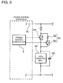
- a surge current protection circuit 51 is configured as a current limiting resistor 52, which prevents surge current from flowing in the load LD, connected in series with a switching device 53.
- the surge current protection circuit 51 is connected in parallel with the discharge switch DS.
- surge current can flow in the load LD and over-current can have detrimental effects on components such as switches and fuses (not illustrated).
- Surge current is primarily due to the charging current for the high capacitance electrolytic capacitor CD connected in parallel with the load LD.
- the surge current protection circuit 51 switching device 53 is turned ON to limit surge current flow in the load LD with the current limiting resistor 52.
- a switch control circuit 6 is connected in parallel with the first equalizing circuits 14 and parallel connecting switches 12 to control the parallel connecting switches 12 and first equalizing switches 16.
- the switch control circuit 6 switches the first equalizing switch 16 in the first equalizing circuit 14 ON with the parallel connecting switch 12 in the OFF state when a battery unit 10 is connected to the load LD (i.e.when the discharge switch DS is turned ON).
- the battery unit 10 is connected to the load LD through the first limiting resistor 15 and the flow of surge current to the load LD and electrolytic capacitor CD is limited by the first limiting resistor 15.
- the maximum value (peak value) of the surge current is determined by the size of the first limiting resistor 15. For example, if the value of the first limiting resistor 15 is 100 ⁇ and the voltage of the battery unit 10 is 250V, the peak value of the surge current is limited to 2.5A.
- the switch control circuit 6 turns the parallel connecting switch 12 ON. After turning the parallel connecting switch 12 ON, the switch control circuit 6 switches the first equalizing switch 16 OFF.
- the switch control circuit 6 could turn the parallel connecting switch 12 ON and the first equalizing switch 16 OFF simultaneously, or the parallel connecting switch 12 could be turned ON immediately after the first equalizing switch 16 is turned OFF.
- Fig. 7 shows a flow-chart for connecting the power source apparatus shown in Fig. 6 with a load LD.
- the flow-chart describes connection of a battery unit 10 with the load LD by the following steps.
- Power is supplied to activate the power source controller 2 enabling it to detect current flow in the load LD.
- the electrolytic capacitor CD in parallel with the load LD becomes charged and surge current no longer flows, the voltage of the battery unit 10 and the voltage on the output line OL become approximately equal and the detected voltage difference drops to within the measurement error range. Specifically, If the voltage difference between the battery unit 10 and the output line OL is within the margin of error for that measurement, the electrolytic capacitor CD in parallel with the load LD is in the charged state and there is no surge current flow.
- surge current in the load LD is detected and compared with as set value, and the voltage difference between the battery unit 10 and the output line OL is also detected to determine if surge current is flowing. Consequently, in this power source apparatus, the parallel connecting switch 12 can be switched ON in a state more reliably determined to have no surge current flow.
- the battery unit described above is in the singular form, the procedure is the same for a plurality of battery units.
- the absence of surge current flow could also be determined by (either) detecting battery unit output current and comparing it with a set value or detecting the voltage difference between the battery unit and the output line.
- the power source apparatus of the present invention can be used advantageously in applications such as a power source apparatus in the home or manufacturing facility that is charged by solar power or late-night (reduced-rate) power.
Landscapes
- Engineering & Computer Science (AREA)
- General Chemical & Material Sciences (AREA)
- Manufacturing & Machinery (AREA)
- Chemical & Material Sciences (AREA)
- Chemical Kinetics & Catalysis (AREA)
- Electrochemistry (AREA)
- Microelectronics & Electronic Packaging (AREA)
- Life Sciences & Earth Sciences (AREA)
- Sustainable Development (AREA)
- Sustainable Energy (AREA)
- Power Engineering (AREA)
- Charge And Discharge Circuits For Batteries Or The Like (AREA)
- Secondary Cells (AREA)
- Battery Mounting, Suspending (AREA)
Abstract
The power source apparatus configuration can be changed to adapt to the installation site and environment. The power source apparatus is provided with first equalizing circuits 14 to control remaining charge capacity variation among a plurality of battery units 10, and second equalizing circuits 24 to control remaining charge capacity variation among all the series-connected battery packs 20 that make up each battery unit 10. A first equalizing circuit 14 connects each battery unit 10 with an output line OL through a first series circuit made up of a first limiting resistor 15 and first equalizing switch 16. Remaining charge capacity variation is equalized among all the battery units 10 by the first equalizing circuits 14, and remaining charge capacity variation between battery packs 20 in each battery unit 10 is controlled by the second equalizing circuits 24. (Cell balancing is performed quickly and efficiently.)
Description
- The present invention relates to a power source apparatus provided with a high capacity array of batteries to obtain both high output voltage and high output current.
- A power source apparatus with both high output voltage and high output current has many batteries (or battery cells) connected in series to increase the output voltage. In this type of power source apparatus, the series-connected batteries are charged by the same current and discharged by the same current. Accordingly, if all the batteries have exactly the same characteristics, no imbalance (between batteries) will develop in battery voltage or remaining charge capacity. However, as a practical matter, batteries cannot be manufactured with exactly the same characteristics. With the repetition of charge-discharge cycles, battery voltage and/or remaining charge capacity imbalance will develop between batteries. Further, battery voltage imbalance can cause over-charging or over-discharging of a specific battery (a battery with low capacity or high internal resistance). To avoid these detrimental effects, a vehicle power source apparatus has been developed with cell balancing capability that detects the voltage of each battery and eliminates imbalance between battery cells.
- Refer to Japanese Laid-Open Patent Publication
2006-149068 - As shown in
Fig. 4 , the vehiclepower source apparatus 40 cited inJP 2006-149068 discharge circuit 42 connected in parallel with eachbattery 41 in the series-connected battery array. Eachdischarge circuit 42 is a series-connection of adischarge resistor 43 and aswitching device 44. In thispower source apparatus 40, abattery 41 that has become high in voltage is discharged through itsdischarge circuit 42 to restore cell balance and eliminate disparity betweenbatteries 41. Adischarge circuit 42 lowers the voltage of aspecific battery 41 by switching theswitching device 44 ON to discharge thebattery 41 through thedischarge resistor 43. - This
power source apparatus 40 can eliminate imbalance between the series-connectedbatteries 41. In this type of power source apparatus, high output voltage can be attained by connecting many batteries in series, but the current capacity is that of the individual batteries. Since the power output of a power source apparatus is proportional to the product of voltage and current, increasing the current can further increase the power output. Specifically, by connecting many batteries in series and parallel, both the output current and output voltage can be increased to further increase the power output of the power source apparatus. In a power source apparatus with many batteries arrayed in series and parallel, voltages of the series-connected batteries can be equalized to eliminate imbalance in the same manner cited inJP 2006-149068 - The present invention was developed considering the types of prior art problems described above. Thus, it is a primary object of the present invention to provide a power source apparatus that can efficiently equalize the battery cells while connecting many cells in series and parallel.
- To achieve the object described above, the power source apparatus of the present invention connects a plurality of battery cells in parallel with a configuration having a plurality of battery cells connected in parallel as battery packs, a plurality of battery packs connected in series as battery units, and a plurality of battery units connected in parallel to an output line. The power source apparatus can be provided with first equalizing circuits to control remaining capacity variation between the plurality of battery units, and second equalizing circuits to control remaining capacity variation between all the series-connected battery packs that make up each battery unit. This configuration eliminates non-uniformity between battery units with the first equalizing circuits, and eliminates non-uniformity between the battery packs included in each battery unit with the second equalizing circuits to maintain cell balance between the many battery cells included in the power source apparatus. Cell balancing is not performed on a cell by cell basis, but rather on a block by block basis achieving the positive feature that cell balance can be restored rapidly and efficiently.
- In the power source apparatus for the second aspect of the present invention, a second equalizing
circuit 24 can be connected in parallel with eachbattery pack 20, and can be provided with a second series circuit configured with a second (current) limitingresistor 25 and a second equalizingswitch 26. This allows non-uniformity between the battery packs in each battery unit to be eliminated via the second equalizing circuits. - In the power source apparatus for the third aspect of the present invention, connections between the
battery packs 20 in eachbattery unit 10 can be made with detachable connectors. This allows easy connection and replacement of battery packs. In particular, when a battery pack malfunctions, it can be easily replaced to shorten apparatus down-time, and since all the battery packs do not need to be replaced, the positive feature of cost reduction is achieved. - In the power source apparatus for the fourth aspect of the present invention, each
battery pack 20 can be configured with a plurality of parallel blocks connected in series, and each parallel block can have a plurality of battery cells 31 connected in parallel. Further, a third equalizingcircuit 34 can be provided with each parallel block to equalize the plurality of parallel blocks in eachbattery pack 20. This allows non-uniformity among the plurality of parallel blocks included in a battery pack to also be eliminated. - In the power source apparatus for the fifth aspect of the present invention, the array of batteries can have a capacity of 1 KVA to 100 KVA.
- In the power source apparatus for the sixth aspect of the present invention,
battery units 10 can be connected to the output line OL in a detachable manner. - The power source apparatus for the seventh aspect of the present invention can be provided with a
power source controller 2 to control parallel connectingswitches 12 and equalizing switches. Thepower source controller 2 can turn a parallel connectingswitch 12 ON to connect abattery unit 10 in parallel, and can turn the parallel connectingswitch 12 OFF and the equalizing switch ON to equalize thebattery unit 10. Compared with (passive cell balancing) methods that consume the surplus power of a high voltage battery unit as resistor heat, this (active cell balancing) method has the positive feature that power can be used effectively to charge lower voltage battery units and increase their voltage, reduce the battery unit voltage difference ΔVU, and reduce the time required for equalization. - In the power source apparatus for the eighth aspect of the present invention, battery cells 31 that make up the
battery packs 20 can be lithium ion batteries. - The power source apparatus for the ninth aspect of the present invention can be provided with a
switch control circuit 6 connected in parallel with the first equalizingcircuits 14 andparallel connecting switches 12 to control theparallel connecting switches 12 and first equalizingswitches 16. At the time of connection of abattery unit 10 to the load LD, theswitch control circuit 6 can turn the first equalizingswitch 16 in the first equalizingcircuit 14 ON to connect thebattery unit 10 to the load LD and limit surge current with a first (current) limitingresistor 15. When there is no surge current flow, theswitch control circuit 6 can turn the parallel connectingswitch 12 ON to connect thebattery unit 10 to the load LD. This can prevent surge current in the load by using the first equalizing circuits for the dual purpose of surge current suppression instead of providing a special-purpose circuit to prevent surge current in the load. The above and further objects of the present invention as well as the features thereof will become more apparent from the following detailed description to be made in conjunction with the accompanying drawings. -
-
Fig. 1 is a block diagram showing a power source system using the power source apparatus of the first embodiment; -
Fig. 2 is a block diagram showing the battery units inFig. 1 during equalization; -
Fig. 3 is a block diagram of one of the battery packs that make up a battery unit inFig. 1 ; -
Fig. 4 is a block diagram showing a prior art power source apparatus; -
Fig. 5 is a block diagram showing one example of a surge current protection circuit connected to the output-side of the power source apparatus shown inFig. 1 ; -
Fig. 6 is a block diagram showing a power source system using the power source apparatus of the second embodiment; and -
Fig. 7 is a flow-chart for connecting the power source apparatus shown inFig. 6 with a load. - The following describes embodiments of the present invention based on the figures. However, the following embodiments are merely specific examples of a power source apparatus representative of the technology associated with the present invention, and the power source apparatus of the present invention is not limited to the embodiments described below. Further, components cited in the claims are in no way limited to the components indicated in the embodiments. In particular, in the absence of specific annotation, structural component features described in the embodiment such as dimensions, raw material, shape, and relative position are simply for the purpose of explicative example and are in no way intended to limit the scope of the invention. Properties such as the size and spatial relation of components shown in the figures may be exaggerated for the purpose of clear explanation. In the descriptions following, components with the same name and label indicate components that are the same or have the same properties and their detailed description is appropriately abbreviated. Further, a single component can serve multiple functions and a plurality of structural elements of the invention can be implemented with the same component. In contrast, the functions of a single component can be divided among a plurality of components. In addition, explanations used to describe part of one embodiment may be used in other embodiments and descriptions.
-
Figs. 1-3 show thepower source apparatus 100 for the first embodiment of the present invention. In these figures,Fig. 1 is a block diagram of the power source system using thepower source apparatus 100,Fig. 2 is a block diagram showing thebattery units 10 inFig. 1 during equalization, andFig. 3 is a block diagram of one of the battery packs 20 that make up abattery unit 10 inFig. 1 . The power source system shown in these figures is provided with apower source apparatus 100, a load LD, and a charging power supply CP. After being charged by the charging power supply CP, thepower source apparatus 100 drives the load LD. Thepower source apparatus 100 has a charging mode, a discharging mode, and an equalizing mode to equalize the battery units 10 (described later). The load LD and the charging power supply CP are connected to thepower source apparatus 100 through a discharge switch DS and a charging switch CS respectively. The discharge switch DS and the charging switch CS are controlled ON and OFF by thepower source apparatus 100power source controller 2. In the charging mode, thepower source controller 2 switches the charging switch CS ON and the discharge switch DS OFF to allow thepower source apparatus 100 to be charged from the charging power supply CP. When charging is completed by reaching full-charge or by charging to a capacity at or above a given level, thepower source apparatus 100 can be switched to the discharging mode depending on demand by the load LD. In the discharging mode, thepower source controller 2 switches the charging switch CS OFF and the discharge switch DS ON to allow discharge from thepower source apparatus 100 to the load LD. Further, depending on requirements, both the charging switch CS and the discharge switch DS can be turned ON to allow power to be simultaneously supplied to the load LD while charging thepower source apparatus 100. - The load LD driven by the
power source apparatus 100 is connected to thepower source apparatus 100 through the discharge switch DS. In the discharging mode, thepower source controller 2 switches the discharge switch DS ON to connect and drive the load LD with power from thepower source apparatus 100. A switching device such as a field effect transistor (FET) can be used as the discharge switch DS. The discharge switch DS is controlled ON and OFF by thepower source apparatus 100power source controller 2. - The charging power supply CP is connected in series with the charging switch CS. The charging switch CS is turned ON to charge the
power source apparatus 100 with the charging power supply CP. Further, when full-charge of thepower source apparatus 100 is detected, the charging switch CS is switched OFF. These switching operations are performed by thepower source controller 2. Power generating systems including those that utilize renewable energy sources such as solar, wind, tidal, and geothermal; or fuel cells, gas power generators, and commercial power sources can be used as the charging power supply CP. In the example ofFig. 1 , solar panels are used as the charging power supply CP. - A switching device such as a FET can also be used as the charging switch CS. The charging switch CS is also controlled ON and OFF by the
power source apparatus 100power source controller 2. The charging switch CS is connected between the charging power supply CP and thepower source apparatus 100 to control charging of thepower source apparatus 100. Charging is not performed by a technique such as voltage conversion through a direct current to direct current (DC/DC) converter, but rather pulse charging is performed using ON and OFF switching of the charging switch CS. This allows high efficiency and simplification of the circuitry. - The
power source apparatus 100 is provided with parallel connectingswitches 12 connected to eachbattery unit 10, first equalizingcircuits 14 to equalize thebattery units 10, OR circuits 4 (logic gates) connected to the parallel connectingswitches 12, the first equalizingcircuits 14, and thebattery units 10, and thepower source controller 2 connected to theOR circuits 4. - Each parallel connecting
switch 12 connects abattery unit 10 to an output line OL to connect thebattery units 10 in parallel through the parallel connecting switches 12. Devices such as insulated gate bipolar transistors (IGBTs) can be used as the parallel connecting switches 12. - Each first equalizing
circuit 14 is configured as a first series circuit with a first limiting resistor 15 (15A and 15B inFig. 1 ) and a first equalizing switch 16 (16A and 16B inFig. 1 ). A device such as a FET can be used as the first equalizingswitch 16. Thefirst equalizing switch 16 and the parallel connectingswitch 12 are controlled ON and OFF in accordance with the charging mode, the discharging mode, and the equalizing mode. During normal operation in the charging mode and the discharging mode, each parallel connectingswitch 12 is in the ON state and each first equalizingswitch 16 is in the OFF state. However, in the equalizing mode, the applicableparallel connecting switch 12 is switched OFF and the applicable first equalizingswitch 16 is switched ON. - The
power source controller 2 is connected with eachbattery unit 10, each ORcircuit 4, the discharge switch DS, and the charging switch CS. Thepower source apparatus 100 shown inFig. 1 has twobattery units 10 connected in parallel, and is controlled by thepower source controller 2 to drive the load LD and charge eachbattery unit 10 with the charging power supply CP. As described above, thepower source controller 2 switches the discharge switch DS and the charging switch CS ON and OFF depending on the mode (charging mode or discharging mode). Further, thepower source controller 2 is connected to eachbattery unit 10, and switches each first equalizingswitch 16 and parallel connectingswitch 12 ON and OFF to perform equalization betweenbattery units 10 in accordance with signals from thebattery units 10. In addition, when thepower source controller 2 receives a signal indicating an abnormality from abattery unit 10 via the input terminal DI of the parent battery pack 20 (described later), thepower source controller 2 controls a parallel connectingswitch 12 to disconnect thatbattery unit 10. Thepower source controller 2 can be made up of circuitry that includes a central processing unit such as a micro-processing unit (MPU). - In the example of
Fig. 1 , a power source apparatus with twobattery units 10 is described. However, it should be clear that it is possible to connect three or more battery units together. Further, although the battery units in this example are controlled by a single power source controller, the power source apparatus can be configured with a plurality of power source controllers when there are a large number of battery units. Still further, although the power source controller in the example ofFig. 1 is separate from the battery units, it can also be disposed inside the battery units. For example, the capabilities of the power source controller can be included in the batterypack control circuit 39 in the parent battery pack 20 (described later). - In addition, the
power source controller 2 is provided with a communication interface to communicate with externally connected equipment. In the example ofFig. 1 , thepower source controller 2 is connected to an external host computer HT and communicates via known protocols such as universal asynchronous receiver transmitter (UART) and recommended standard-232 (RS-232C) protocols. Further, depending on requirements, a user interface can be provided to allow direct user control of the power source system. For example, an input device such as a keyboard, mouse, touch-panel, or console (terminal) can be connected as a user interface for the power source controller, and inputs can be made such as specifying the maximum current or setting the utilization of connected battery units. An indicator panel or warning lights can also be provided to alert the user when abattery pack 20 abnormality develops. - In this
power source apparatus 100, the output voltage (unit voltage) of the twobattery units power source controller 2 during the discharging mode. When the battery unit voltage difference ΔVU is greater than or equal to a battery unit threshold voltage (such as 1V), the system transitions to the equalizing mode to equalize thebattery units 10. In eachbattery unit 10, the total voltage of theparent battery pack 20 and each child battery pack 20 (described later) is computed by the batterypack control circuit 39 in the parent battery pack, and that total is sent to thepower source controller 2 as the battery unit voltage. The sum of the output voltages of all the battery packs 20 in eachbattery unit 10 can also be computed in thepower source controller 2, and a voltage sensor can also be provided with each battery unit. The equalization process discharges the battery unit with high voltage and charges the battery unit with low voltage. Here, eachbattery pack 20 has lithium ion rechargeable batteries as battery cells 31, has twenty four cells connected in parallel, and is a series-connection of thirteen of the parallel connected cells. This type ofbattery pack 20 has a specified output voltage of 50V and output current of 30A. - As one example, equalization is described based on
Fig. 2 when the voltage ofbattery unit 10A becomes greater than the voltage ofbattery unit 10B. First, to transition to the equalizing mode, thepower source controller 2 turns OFF the charging switch CS and the discharge switch DS. Thepower source controller 2 turns the parallel connectingswitch 12A inbattery unit 10A OFF and thefirst equalizing switch 16A ON. Meanwhile, the parallel connectingswitch 12B inbattery unit 10B is left in the ON state and thefirst equalizing switch 16B is left in the OFF state the same as in the discharging mode. This connectsbattery unit 10A withbattery unit 10B through the first series circuit ofbattery unit 10A as shown by the arrows inFig. 2 . As a result, current flows through the first limitingresistor 15A from the highvoltage battery unit 10A to the lowvoltage battery unit 10B to chargebattery unit 10B frombattery unit 10A. Specifically, the voltage ofbattery unit 10A decreases due to discharging, and the voltage ofbattery unit 10B increases due to charging. Consequently, the battery unit voltage difference ΔVU decreases, and thepower source controller 2 switches out of the equalizing mode to return to the normal discharging mode when the battery unit voltage difference ΔVU becomes less than or equal to the threshold voltage. Note that equalization is not performed during the charging mode. Thepower source controller 2 monitors the battery unit voltage difference ΔVU to determine whether or not to perform battery unit equalization after completing charging of eachbattery unit 10 at the point of transition to the discharging mode. - Compared with methods that consume the surplus power of a high voltage battery unit as heat in a resistor, the technique described above can utilize battery unit power in an effective manner. In addition, since the voltage of the low voltage battery unit increases due to charging to reduce the battery unit voltage difference ΔVU, it has the positive feature that the time required for equalization can be reduced.
- A
battery unit 10 is made up of a plurality of connected battery packs 20. Eachbattery unit 10 is connected to the output line OL through a parallel connectingswitch 12. In the example ofFig. 1 ,battery unit 10A andbattery unit 10B are the same type ofbattery units 10. As mentioned previously, although twobattery units 10 are used in the figures, it is also possible to connect three or more battery units. - In a
battery unit 10 with a plurality of battery packs 20 connected together, one of the battery packs 20 functions as the parent battery pack with the other battery packs 20 serving as child battery packs controlled by the parent battery pack. The parent battery pack monitors the child battery packs and reports status to thepower source controller 2. In the example ofFig. 1 , the parent battery pack and child battery packs are configured as the same type ofbattery pack 20. Specifically, all the battery packs 20 are made with a common structure and since abattery pack 20 can function as a parent battery pack or a child battery pack depending on the connecting configuration, manufacturing cost can be reduced. In the example ofFig. 1 , thebattery pack 20 connected at the lower end of thebattery unit 10 is used as the parent battery pack, and all the other battery packs 20 are used as child battery packs. - Each
battery pack 20 inFig. 1 is provided with signal terminals and power terminals. A battery pack input terminal DI, a battery pack error output terminal DA, and a battery pack output terminal DO are provided as signal terminals for the batterypack control circuit 39. The battery pack input terminal DI is a terminal for inputting signals from other battery packs and thepower source controller 2. In contrast, the battery pack output terminal DO is a terminal for outputting signals to other battery packs and thepower source controller 2. The battery pack error output terminal DA is a terminal for outputting information conveying battery pack abnormality outside the battery pack. In the example ofFig. 1 , battery pack error output terminals DA are connected to theOR circuits 4. - Each
battery pack 20 is also provided with a positive terminal and a negative terminal as output terminals for the battery cells 31 connected together in thebattery pack 20. Positive terminals and negative terminals of adjacent battery packs 20 are connected to connect the battery packs 20 series and increase output voltage. - As mentioned, each
battery unit 10 inFig. 1 includes one parent battery pack and a plurality of child battery packs. The parent battery pack and child battery packs are connected in a string arrangement. To connect the signal terminals of adjacent battery packs 20 together, the output terminal DO of theprevious battery pack 20 is connected to the input terminal DI of thenext battery pack 20. The input terminal DI of the parent battery pack is connected with the output of thepower source controller 2. Further, the output terminal DO of the last child battery pack is left unconnected. Note in this type of daisy-chain connection, the output terminal DO of the last child battery pack can also be connected to a terminator such as a termination resistor to indicate the position of the end of the signal line. The battery pack input terminal DI, battery pack error output terminal DE, and battery pack output terminal DO connect to two signal lines for data communication with thepower source controller 2. Data communication can be via a method such as packet communication that designates the destination of transmission. Here, each battery pack has a preassigned unique identifier (address), and packets for packet communication include the address of the destination battery pack and commands issued to that battery pack. This allows data communication targeted to individual battery packs over a common signal line. Methods of assigning a unique address to each battery pack are applied as appropriate and include automatic allocation by the power source controller depending on the battery pack connecting scheme, and manual setting of switches such as dual inline package (DIP) switches in each battery pack. For example, addresses can be set when the user presses a specially provided address setting switch, or when connection of a child battery pack is detected automatically by the parent battery pack. Or, in the case of a terminator connected to the output terminal DO of the last child battery pack, address setting can be performed when the terminator is connected. For example, a detection device such as a micro-switch or shorting pin can be disposed in the connecting region of the of the battery pack output terminal DO, and when the terminator is connected, the micro-switch physically closes or the detection signal line short circuits to automatically activate address allocation. In this case, it is desirable to establish a detection signal line separate from the power line and other signal lines. As a procedure for address allocation, first the child battery pack with the terminator connected obtains its address, and subsequently a signal is sent to allocate the address of the next connected child battery pack. In this manner, address allocation signals are successively issued to the child battery packs in their connection order. Finally, the parent battery pack receives an address, the fact that addresses have been allocated to all the battery packs is recognized, and the address allocation process is ended. - With this type of connection, the parent battery pack can acquire battery data (such as battery voltage, temperature, and error data) from each child battery pack using a communication protocol (for example, a protocol that uses a master-slave relation) such as RS-485. Various data signals can be communicated from the parent battery pack to the
power source controller 2 via a communication protocol such as RS-485. - In the example of
Fig. 1 , eachbattery unit 10 has one parent battery pack and four child battery packs connected for a total of five battery packs 20 in each battery unit 10 (in the figure, each battery unit is shown as a column of three battery packs with two battery packs not shown). Signal line connection between battery packs 20 is made by detachable connectors. This allows battery packs 20 to be easily connected and disconnected, which is advantageous during maintenance operations. - Each battery pack error output terminal DA is connected to an OR
circuit 4. An ORcircuit 4 is provided with eachbattery unit 10. Accordingly, in eachbattery unit 10, one parent battery pack and four child battery packs are connected to theOR circuit 4. If a stop-signal (error signal) is output to theOR circuit 4 from any one of the battery packs, the parallel connectingswitch 12 is opened to disconnect that battery pack (and its associated battery unit) from the power source apparatus. In this manner, even if a battery pack malfunction develops, all other battery packs can be protected by disconnecting the affected battery pack (and its associated battery unit). Malfunctions include abnormal conditions such as over-charging and over-discharging. In addition, thepower source controller 2 receives signals indicating the error condition and notifies the user urging replacement of the affected battery pack. Power source system recovery can be achieved by the user replacing only the affected battery pack. This system architecture can reduce repair cost by making it possible to replace only the affected battery pack, and since battery pack replacement is made simple by the use of detachable connectors, maintainability is improved. - The OR
circuits 4 are connected with thepower source controller 2 through a common bus line. The ORcircuit 4 provided with eachbattery unit 10 is connected to the parallel connectingswitch 12 and to thepower source controller 2. As described later, thepower source controller 2 turns the parallel connectingswitch 12 OFF and notifies the user forbattery pack 20 replacement when it receives an error signal from the batterypack control circuit 39 in abattery unit 10. For example, thepower source controller 2 can urge battery pack replacement by sending that information from its communication interface to externally connected equipment. Or, thepower source controller 2 can convey the need for battery pack replacement to the user by display on an indicator panel or by illumination of warning lights. - Note that system architecture is not limited to that of the example shown in
Fig. 1 . For example, it is also possible to transmit output from each battery pack error output terminal directly to the power source controller. - Each
battery pack 20 is provided with asecond equalizing circuit 24 configured as a second series circuit having a second limitingresistor 25 and asecond equalizing switch 26. Turning toFig. 3 , a second series circuit is connected in parallel with eachbattery pack 20, and those second equalizingcircuits 24 operate to eliminate non-uniformity among the battery packs 20. - The
second equalizing circuits 24 operate to equalizebattery pack 20 voltages to eliminate imbalance. Abattery pack 20 with high voltage is discharged through the second limitingresistor 25 of thesecond equalizing circuit 24. However, the present invention does not limit the equalizing circuits to circuitry that discharges batteries through current limiting resistors (passive cell balancing). For example, an equalizing circuit could discharge a high voltage battery into a charge storage device such as a capacitor or another battery, and transfer that accumulated charge by discharging the charge storage device to a low voltage battery to eliminate voltage differences between batteries (active cell balancing). - The
second equalizing circuit 24 shown inFig. 3 has the second limitingresistor 25 and second equalizingswitch 26 connected in series as the second series circuit. Thepower source controller 2 or the battery pack control circuit 39 (described later) detects the voltages of eachbattery pack 20 and equalizes the battery packs 20 in abattery unit 10 by controlling the second equalizing switches 26 ON and OFF. A second series circuit having a second limitingresistor 25 and second equalizingswitch 26 is connected in parallel with eachbattery pack 20. When the voltage of abattery pack 20 becomes high, the second equalizingswitch 26 of thesecond equalizing circuit 24 is switched ON by the batterypack control circuit 39, and thebattery pack 20 is discharged through the second limitingresistor 25 to reduce and equalizebattery pack 20 voltage. - Battery
pack control circuits 39 provided with micro-processors comparebattery pack 20 voltages, and control the second equalizing switches 26 to equalize the voltages of all the battery packs 20. In abattery pack 20 with voltage greater that a set threshold voltage (battery pack threshold voltage), the batterypack control circuit 39 switches ON the second equalizingswitch 26 in the second series circuit connected with thatbattery pack 20. As thebattery pack 20 discharges, its voltage decreases. When battery pack voltage drops to a value equal to the voltage of the other battery packs, the second equalizingswitch 26 is turned OFF. When the second equalizingswitch 26 is turned OFF, battery pack discharge stops. In this manner, batterypack control circuits 39 discharge the high voltage battery packs to equalize the voltages of all the battery packs. -
Fig. 3 shows a block diagram of one of the battery packs 20 included in abattery unit 10. Thisbattery pack 20 is connected as a parent battery pack in the example ofFig. 1 . As shown inFig. 3 , thebattery pack 20 is provided with an assembly of battery cells 31 having a plurality of cells connected in series and parallel, a current fuse connected in series with the assembly of battery cells 31, abattery monitoring circuit 33, a battery packcurrent detection circuit 37, and a batterypack control circuit 39 primarily made up of a micro-processor with the capability to judge cell balance. Thebattery pack 20 is housed in a battery pack case. A standard 19-inch rack-mount case such as that used in server computer back-up power supplies can be used as the battery pack case. This can improve versatility by utilizing a commonly available chassis such as a server rack. - The current fuse physically opens the circuit in an over-current situation to protect the
battery pack 20. Thebattery monitoring circuit 33 detects the voltage of each block of parallel-connected battery cells 31 and sends that data to the batterypack control circuit 39. The batterypack control circuit 39 detectsbattery pack 20 over-charging in the charging mode and protects the battery cells 31 from over-charging by limiting the charging current. Similarly, in the discharging mode, the batterypack control circuit 39 detectsbattery pack 20 over-discharging and protects the battery cells 31 from over-discharging by limiting the discharge current. - Also in the example of
Fig. 3 , the battery pack input terminal DI and battery pack output terminal DO are connected to the batterypack control circuit 39 via isolation devices. In addition, the battery pack error output terminal DA is connected to the batterypack control circuit 39 via a photo-coupler (optical isolation device). This isolates each signal terminal with respect to external connection. - In this manner, when a plurality of battery packs 20 are connected to form large power source apparatus, the number of connected battery packs 20 can be adjusted to easily meet the requirements of large-scale applications. Further, even if malfunction occurs in a battery cell, only the battery pack that includes that battery cell needs to be isolated from the system and replaced. This has the positive feature that replacement costs can be reduced.
- The battery pack
current detection circuit 37 detects charging and discharging current and sends that data to the batterypack control circuit 39. For example, the battery packcurrent detection circuit 37 can detect battery pack current from the voltage across a current detection resistor connected in series with the battery pack 30. - Temperature sensors that detect battery cell 31 temperature and voltage sensors that detect the voltage of each block of parallel-connected battery cells 31 are connected to the
battery monitoring circuit 33. Thermistors can be used as the temperature sensors. Thebattery monitoring circuit 33 detects over-charging or over-discharging based on battery cell 31 temperature and battery cell 31 or parallel block voltage. If over-charging or over-discharging is detected, a signal is output to theOR circuit 4 from the battery pack error output terminal DA to open the parallel connectingswitch 12 and disconnect the battery unit containing the affected battery pack. As described below, this capability is employed when error detection by the batterypack control circuit 39 does not function properly. - Data such as battery voltage values converted by analog to digital (A/D) conversion are output from the
battery monitoring circuit 33 to the batterypack control circuit 39. Based on battery voltage values, conditions such as over-charging and over-discharging are judged in the batterypack control circuit 39. In the event of an error condition such as over-charging or over-discharging, error data is transmitted from the child battery packs to the parent battery pack. In addition, values such as battery voltage for each battery pack are transmitted as data from the child battery packs to the parent battery pack. - In a
battery unit 10, if an error condition occurs in a child battery pack or in the parent battery pack, the batterypack control circuit 39 of the parent battery pack communicates that to thepower source controller 2. In that situation, thepower source controller 2 turns the parallel connecting switch 12 (for that battery unit 10) OFF via the ORcircuit 4. The batterypack control circuit 39 in the parent battery pack also acquires the battery voltages of the child battery packs and the parent battery pack, adds those voltages to obtain a total value, and transmits that total to thepower source controller 2. - Each
battery pack 20 has parallel blocks with a plurality of battery cells 31 connected in parallel, and a plurality of parallel blocks are in turn connected in series. However, it is also possible for a battery pack to have no series-connected battery cells and only parallel-connected battery cells. In the example ofFig. 3 , since the assembly of batteries is made up of parallel blocks with twenty four parallel-connected battery cells 31 and thirteen parallel blocks in turn connected in series, a total of 312 battery cells 31 are used in thebattery pack 20. Thisbattery pack 20 is used with a specified voltage of 50V and a specified current of 30A. Since abattery unit 10 shown inFig. 1 is made up of five series-connected battery packs 20, eachbattery unit 10 uses a total of 1560 battery cells 31 to achieve a specified voltage of 250V and a specified current of 30A. Further, by connecting a plurality of these battery units in parallel, a high reliability power source apparatus is formed. The total number of batteries used sets the capacity of the array of batteries depending on the application. For example, capacity can be 1 KVA to 100 KVA. - Besides circular cylindrical battery cells that are elongated in one direction, battery cells that have rectangular outer cases can be used as the battery cells 31. Rechargeable batteries such as lithium ion rechargeable batteries, nickel hydride batteries, and nickel cadmium batteries are appropriate for use as battery cells 31. In particular, the use of lithium ion rechargeable batteries is desirable. Since lithium ion rechargeable batteries have high energy density (charge capacity density), they are appropriate for compactness and weight reduction. Further, compared with nickel hydride batteries and lead storage batteries, lithium ion rechargeable batteries can be charged and discharged over a wider temperature range allowing efficient charging and discharging.
- Use of iron phosphate-system materials is desirable for the battery cell 31 positive electrode. This allows the margin of safety to be increased and charging and discharging temperature dependence to be suppressed. In particular, since relatively high charging and discharging efficiency can be maintained even at low temperatures, efficient charging and discharging is possible even in winter.
- Further, the positive electrode of the lithium ion rechargeable battery can be a three-component electrode. This type of lithium ion rechargeable battery uses a mixture of Li-Ni-Mn-Co compound oxides and lithium cobalt oxide instead of just lithium cobalt oxide used in prior art. By using the three components Ni-Mn-Co in addition to lithium in the positive electrode of this type of lithium ion rechargeable battery, high voltage charging can be performed with good thermal stability, and the maximum charging voltage can be increased to 4.3V to increase charge capacity.
- However, it is desirable to intentionally set the battery cell 31 charging voltage lower than the voltage for determining full-charge. For example, in the case of a lithium ion rechargeable battery, although full-charge is determined around 4.2V under normal conditions, the voltage for judging full-charge is set to 4V. This contributes to lengthening battery cell lifetime.
- For the configuration shown in
Fig. 3 , the specified voltage is used as the nominal voltage of the battery pack, which is made up of battery cells 31 (for lithium ion battery cells, the voltage is approximately 3.7V to 4.0V per cell times the number of series-connections). It is desirable to choose the nominal voltage below the maximum output operating voltage Vop of the solar cell panel, which is the charging power supply CP. More preferably, the specified voltage is selected to be 70% to 90% of Vop. Since there are inter-related effects between the solar panel operating voltage and battery pack voltage, charging power drops for a battery pack voltage that is far from Vop. Compared with battery pack voltage as a function of depth of discharge, the relative voltage of the solar panel increases. Accordingly, when charging to full-charge, it is preferable for the voltage near the full-charge state to approach Vop. It is also necessary to select an appropriate battery pack voltage considering solar panel voltage variation with temperature. Therefore, a battery pack voltage in the range mentioned above is preferable. - By selecting a voltage in the range cited above, the present embodiment can charge the battery cells 31 without a DC/DC converter and avoid internal power loss that accompanies DC/DC converter use. This enables high efficiency charging, eliminates any need for DC/DC converter replacement, and reduces the number of parts in the system. As a result, increased reliability due to lower failure rate, reduced cost, and improved prospects for long-term maintenance-free operation can be achieved. Since the voltage in the present embodiment is within the range mentioned above, a DC/DC converter is unnecessary for battery cell 31 charging.
- A battery
pack control circuit 39, which is provided with the capability to judge cell balance, controls equalization of the voltages of the battery packs 20 connected in series in abattery unit 10 via the previously described secondequalizing circuits 24. As described above, the batterypack control circuit 39 in thebattery pack 20 acting as the parent battery pack acquires the voltages of eachbattery pack 20 in thebattery unit 10, compares those voltages, and maintains cell balance by discharging battery packs 20 when necessary. - Each block of parallel-connected battery cells 31 is provided with a
third equalizing circuit 34 to eliminate non-uniformity among parallel blocks. Athird equalizing circuit 34 is connected in parallel with each parallel block. Each third equalizingcircuit 34 is configured as a third series circuit provided with a third limitingresistor 35 and athird equalizing switch 36 connected in parallel with each parallel block. The third equalizing switches 36 are controlled ON and OFF by the batterypack control circuit 39. - Third equalizing
circuits 34 eliminate voltage imbalance among the blocks of parallel-connected battery cells 31. Thethird equalizing circuits 34 inFig. 3 discharge parallel blocks with high voltage through the third limitingresistors 35 to eliminate voltage imbalance. Athird equalizing circuit 34 is provided with a third series circuit, which is the third limitingresistor 35 connected in series with the third equalizingswitch 36. The batterypack control circuit 39 detects the voltage of each parallel block, and controls the third equalizing switches 36 ON and OFF to equalize the parallel blocks in abattery pack 20. Third series circuits made up of third limitingresistors 35 and third equalizing switches 36 are connected in parallel with each block of parallel-connected battery cells 31. When the voltage of any parallel block exceeds a set threshold voltage (parallel block threshold voltage), the batterypack control circuit 39 switches ON the third equalizingswitch 36 in the third series circuit connected with that parallel block. As a result, that block of parallel-connected battery cells 31 discharges through the third limitingresistor 35 and the voltage of the parallel block decreases. When the voltage drops to a given parallel block voltage, equalization of that parallel block is complete and the third equalizingswitch 36 is turned OFF. The batterypack control circuit 39 compares voltages between all of the parallel blocks, and controls the third equalizing switches 36 to equalize the voltages of all the parallel blocks. - In this manner, power source apparatus imbalance between battery units is eliminated by first equalizing
circuits 14, imbalance between battery packs inside a battery unit is eliminated by second equalizingcircuits 24, and imbalance between blocks of parallel-connected battery cells inside a battery pack is eliminated by third equalizingcircuits 34. By performing equalization in this three-level hierarchical division, imbalance can be efficiently eliminated even in a power source apparatus employing many battery cells, and battery cells can be used in a stable manner over a long period to improve system reliability. Especially in a large-scale power source apparatus with output power increased by using many battery cells, there is concern that if any battery cell becomes unusable, the entire power source apparatus will also become unusable. Therefore, it is particularly important for operation to proceed in a manner that allows each battery cell to be used under optimally stable conditions. Specifically, this issue can be addressed by operating under conditions that maintain cell balance and minimize (to the extent possible) imbalance between battery cells. - Although not illustrated, the power source apparatus shown in
Fig. 1 can also have a surge current protection circuit connected to its output-side. As shown inFig. 5 , a surgecurrent protection circuit 51 is configured as a current limitingresistor 52, which prevents surge current from flowing in the load LD, connected in series with aswitching device 53. In the circuit ofFig. 5 , the surgecurrent protection circuit 51 is connected in parallel with the discharge switch DS. When the discharge switch DS in the power source apparatus ofFig. 5 is switched ON, surge current can flow in the load LD and over-current can have detrimental effects on components such as switches and fuses (not illustrated). Surge current is primarily due to the charging current for the high capacitance electrolytic capacitor CD connected in parallel with the load LD. With the discharge switch DS in the OFF state; the surgecurrent protection circuit 51switching device 53 is turned ON to limit surge current flow in the load LD with the current limitingresistor 52. - In the system architecture of
Fig. 5 , it is necessary to establish a special-purpose surgecurrent protection circuit 51. However, in the power source apparatus with the circuit structure shown inFig. 6 , surge current in the load LD can be prevented by using the first equalizingcircuits 14 for the dual purpose of surge current protection while eliminating any special-purpose surge current protection circuit. - In the power source apparatus shown in
Fig. 6 , aswitch control circuit 6 is connected in parallel with the first equalizingcircuits 14 and parallel connectingswitches 12 to control the parallel connectingswitches 12 and first equalizing switches 16. Theswitch control circuit 6 switches the first equalizingswitch 16 in the first equalizingcircuit 14 ON with the parallel connectingswitch 12 in the OFF state when abattery unit 10 is connected to the load LD (i.e.when the discharge switch DS is turned ON). Under these conditions, thebattery unit 10 is connected to the load LD through the first limitingresistor 15 and the flow of surge current to the load LD and electrolytic capacitor CD is limited by the first limitingresistor 15. The maximum value (peak value) of the surge current is determined by the size of the first limitingresistor 15. For example, if the value of the first limitingresistor 15 is 100Ω and the voltage of thebattery unit 10 is 250V, the peak value of the surge current is limited to 2.5A. - The surge current gradually decreases and the load LD electrolytic capacitor CD becomes charged. When surge current no longer flows, the
switch control circuit 6 turns the parallel connectingswitch 12 ON. After turning the parallel connectingswitch 12 ON, theswitch control circuit 6 switches the first equalizingswitch 16 OFF. However, other switching event timing is also possible. Theswitch control circuit 6 could turn the parallel connectingswitch 12 ON and the first equalizingswitch 16 OFF simultaneously, or the parallel connectingswitch 12 could be turned ON immediately after the first equalizingswitch 16 is turned OFF. -
Fig. 7 shows a flow-chart for connecting the power source apparatus shown inFig. 6 with a load LD. - The flow-chart describes connection of a
battery unit 10 with the load LD by the following steps. - In step n=1, the
switch control circuit 6 switches ON the first equalizingswitch 16 in the first equalizingcircuit 14 prior to connecting thebattery unit 10 to the load LD. Specifically, after theswitch control circuit 6 turns ON the first equalizingcircuit 14 first equalizingswitch 16, it switches ON the discharge switch DS in step n=2. Under these conditions, thebattery unit 10 is connected to the load LD via the first limitingresistor 15, and the electrolytic capacitor CD in parallel with the load LD is charged while suppressing surge current. - Power is supplied to activate the
power source controller 2 enabling it to detect current flow in the load LD. - Current output from the
battery unit 10 to the load LD is detected in step n=4, and step n=5 judges whether or not the detected current is less than or equal to a set value. If the detected current is less than or equal to the set value, control jumps to step n=8 where the parallel connectingswitch 12 is turned ON. - If the detected current is greater than the set value, the difference between the
battery unit 10 voltage and the output line OL voltage, which is the voltage across the first limitingresistor 15, is detected in step n=6. Step n=7 judges whether or not the detected voltage difference is within the margin (range) of error of the voltage measurement. If the detected voltage difference is within the margin of error, control proceeds to step n=8 where the parallel connectingswitch 12 is turned ON. If the voltage difference is not within the margin of error, control loops back to step n=4. - If the electrolytic capacitor CD in parallel with the load LD becomes charged and surge current no longer flows, the voltage of the
battery unit 10 and the voltage on the output line OL become approximately equal and the detected voltage difference drops to within the measurement error range. Specifically, If the voltage difference between thebattery unit 10 and the output line OL is within the margin of error for that measurement, the electrolytic capacitor CD in parallel with the load LD is in the charged state and there is no surge current flow. - After connecting the
battery unit 10 to the load by switching ON the parallel connectingswitch 12 in step n=8, the first equalizingswitch 16 is turned OFF in step n=9. - In the manner described above, surge current in the load LD is detected and compared with as set value, and the voltage difference between the
battery unit 10 and the output line OL is also detected to determine if surge current is flowing. Consequently, in this power source apparatus, the parallel connectingswitch 12 can be switched ON in a state more reliably determined to have no surge current flow. Note although the battery unit described above is in the singular form, the procedure is the same for a plurality of battery units. - Note further that the absence of surge current flow could also be determined by (either) detecting battery unit output current and comparing it with a set value or detecting the voltage difference between the battery unit and the output line.
- The power source apparatus of the present invention can be used advantageously in applications such as a power source apparatus in the home or manufacturing facility that is charged by solar power or late-night (reduced-rate) power.
-
- 100
- POWER SOURCE APPARATUS
- 2
- POWER SOURCE CONTROLLER
- 4
- OR CIRCUIT
- 6
- SWITCH CONTROL CIRCUIT
- 10, 10A, 10B
- BATTERY UNIT
- 12, 12A, 12B
- PARALLEL CONNECTING SWITCH
- 14
- FIRST EQUALIZING CIRCUIT
- 15, 15A, 15B
- FIRST LIMITING RESISTOR
- 16, 16A, 16B
- FIRST EQUALIZING SWITCH
- 20
- BATTERY PACK
- 24
- SECOND EQUALIZING CIRCUIT
- 25
- SECOND LIMITING RESISTOR
- 26
- SECOND EQUALIZING SWITCH
- 31
- BATTERY CELL
- 32
- CURRENT FUSE
- 33
- BATTERY MONITORING CIRCUIT
- 34
- THIRD EQUALIZING CIRCUIT
- 35
- THIRD LIMITING RESISTOR
- 36
- THIRD EQUALIZING SWITCH
- 37
- BATTERY PACK CURRENT DETECTION CIRCUIT
- 39
- BATTERY PACK CONTROL CIRCUIT
- 40
- POWER SOURCE APPARATUS
- 41
- BATTERY
- 42
- DISCHARGE CIRCUIT
- 43
- DISCHARGE RESISTOR
- 44
- SWITCHING DEVICE
- 51
- SURGE CURRENT PROTECTION CIRCUIT
- 52
- CURRENT LIMITING RESISTOR
- 53
- SWITCHING DEVICE
- LD
- LOAD
- CP
- CHARGING POWER SUPPLY
- CD
- ELECTROLYTIC CAPACITOR
- DS
- DISCHARGE SWITCH
- CS
- CHARGING SWITCH
- HT
- HOST COMPUTER
- OL
- OUTPUT LINE
- DI
- BATTERY PACK INPUT TERMINAL
- DA
- BATTERY PACK ERROR OUTPUT TERMINAL
- DO
- BATTERY PACK OUTPUT TERMINAL
Claims (14)
- A power source apparatus with a plurality of battery cells connected in series and parallel having battery packs configured with a plurality of battery cells connected in parallel, battery units configured with a plurality of battery packs connected in series, and a plurality of battery units connected in parallel to an output line comprising:first equalizing circuits to control remaining charge capacity variation between the battery units; andsecond equalizing circuits to control remaining charge capacity variation between all the series-connected battery packs that make up each battery unit.
- The power source apparatus as cited in claim 1 further comprising parallel connecting switches between the battery units and the output line,
wherein each first equalizing circuit is made up of a first (current) limiting resistor connected in series with a first equalizing switch, and each first equalizing circuit is connected between a battery unit and the output line in parallel with each parallel connecting switch. - The power source apparatus as cited in claim 2 further comprising a switching section that switches the parallel connecting switches and first equalizing switches according to remaining charge capacity variation between the battery units.
- The power source apparatus as cited in any one of the claims 1-3 wherein each second equalizing circuit is made up of a second (current) limiting resistor and a second equalizing switch connected in series, and a second equalizing circuit is connected in parallel with each battery pack.
- The power source apparatus as cited in any one of the claims 1-4 wherein connections between the battery packs in each battery unit are made with detachable connectors.
- The power source apparatus as cited in any one of the claims 1-5 wherein each battery pack is configured with a plurality of parallel blocks connected in series, each parallel block has a plurality of battery cells connected in parallel, and a third equalizing circuit is provided with each parallel block to control remaining charge capacity variation between the parallel blocks.
- The power source apparatus as cited in any one of the claims 1-6 wherein the battery array configured with a plurality of battery cells has a charge capacity of 1 KVA to 100 KVA.
- The power source apparatus as cited in any one of the claims 1-7 wherein the plurality of battery units is connected to the output line in a detachable manner.
- The power source apparatus as cited in any one of the claims 2, or 4-8 further comprising a power source controller to control the parallel connecting switches and the first equalizing switches,
wherein the power source controller connects a battery unit in parallel by turning a parallel connecting switch ON, and
wherein controls remaining charge capacity variation between battery units by turning a first equalizing switch ON with the parallel connecting switch in the OFF state. - The power source apparatus as cited in claim 3 wherein when equalizing remaining charge capacity variation between the battery units, the switching section turns the parallel connecting switch OFF and the first equalizing switch ON for the high voltage battery unit; and turns the parallel connecting switch ON with the first equalizing switch OFF for the low voltage battery unit.
- The power source apparatus as cited in any one of the claims 1-10 wherein the battery cells that make up the battery packs are lithium ion batteries.
- The power source apparatus as cited in either of the claims 3 or 10 wherein when connecting a battery unit to the load, the switching section initially turns the first equalizing switch ON with the parallel connecting switch in the OFF state; and after a given time period, the switching section turns the parallel connecting switch ON and the first equalizing switch OFF.
- The power source apparatus as cited in any one of the claims 2, 4-9, or 11 further comprising a switch control circuit connected in parallel with the first equalizing circuits and the parallel connecting switches to control the parallel connecting switches and first equalizing switches;
at the time of connection of a battery unit to the load, the switch control circuit turns the first equalizing switch in the first equalizing circuit ON to connect the battery unit to the load LD and limit surge current with the first (current) limiting resistor;
when there is no surge current flow, the switch control circuit turns the parallel connecting switch ON to connect the battery unit to the load. - A power source apparatus with a plurality of battery cells connected in series and parallel having battery packs configured with a plurality of battery cells connected in parallel, battery units configured with a plurality of battery packs connected in series, and a plurality of battery units connected in parallel to an output line comprising:first equalizing circuits to control remaining charge capacity variation between the battery units.
Applications Claiming Priority (3)
| Application Number | Priority Date | Filing Date | Title |
|---|---|---|---|
| JP2010025984 | 2010-02-08 | ||
| JP2010107761A JP5143185B2 (en) | 2010-02-08 | 2010-05-07 | Power supply |
| PCT/JP2011/052143 WO2011096430A1 (en) | 2010-02-08 | 2011-02-02 | Power supply device |
Publications (1)
| Publication Number | Publication Date |
|---|---|
| EP2536001A1 true EP2536001A1 (en) | 2012-12-19 |
Family
ID=44355426
Family Applications (1)
| Application Number | Title | Priority Date | Filing Date |
|---|---|---|---|
| EP11739778A Withdrawn EP2536001A1 (en) | 2010-02-08 | 2011-02-02 | Power supply device |
Country Status (5)
| Country | Link |
|---|---|
| US (1) | US9030167B2 (en) |
| EP (1) | EP2536001A1 (en) |
| JP (1) | JP5143185B2 (en) |
| CN (2) | CN102754301B (en) |
| WO (1) | WO2011096430A1 (en) |
Cited By (7)
| Publication number | Priority date | Publication date | Assignee | Title |
|---|---|---|---|---|
| EP2724440A4 (en) * | 2011-09-02 | 2015-08-12 | Samsung Sdi Co Ltd | DATA TRANSMISSION METHOD, DATA TRANSMITTING APPARATUS, AND ENERGY STORAGE SYSTEM INCLUDING THE SAME |
| EP2747238A3 (en) * | 2012-12-20 | 2017-03-15 | Nokia Technologies Oy | Balancing of battery cells connected in parallel |
| EP3236557A1 (en) * | 2016-04-21 | 2017-10-25 | enfas GmbH | Energy storage system |
| EP2639923A3 (en) * | 2012-03-15 | 2018-01-24 | Hitachi, Ltd. | Battery system |
| EP3393000A4 (en) * | 2016-10-21 | 2019-01-30 | LG Chem, Ltd. | CHARGE VOLTAGE SUPPLY DEVICE AND SUPPLY PROCESS |
| FR3141294A1 (en) * | 2022-10-21 | 2024-04-26 | Vitesco Technologies | Battery activation of an electrical power system for a vehicle by a precharging circuit |
| EP4572076A4 (en) * | 2022-11-08 | 2025-11-19 | Contemporary Amperex Technology Hong Kong Ltd | BATTERY SYSTEM, CONTROL METHOD, CONTROL UNIT AND STORAGE MEDIUM |
Families Citing this family (90)
| Publication number | Priority date | Publication date | Assignee | Title |
|---|---|---|---|---|
| JP5722875B2 (en) * | 2009-04-10 | 2015-05-27 | ザ リージェンツ オブ ザ ユニバーシティ オブ ミシガン | Dynamically reconfigurable structure for large battery systems |
| FR2971645B1 (en) * | 2011-02-10 | 2014-02-28 | Commissariat Energie Atomique | DEVICE FOR PROTECTING A VOLTAGE SOURCE AGAINST CURRENT OVERCURRENT |
| US20120248868A1 (en) * | 2011-04-04 | 2012-10-04 | Fahim Usshihab Mobin | Swappable battery car and battery car station |
| CN102754245B (en) | 2011-04-18 | 2014-02-19 | 华为终端有限公司 | Battery, battery component and subscriber equipment |
| US9341678B2 (en) * | 2011-09-28 | 2016-05-17 | Alliance For Sustainable Energy, Llc | Fail-safe designs for large capacity battery systems |
| JP2013078227A (en) * | 2011-09-30 | 2013-04-25 | Sanyo Electric Co Ltd | Remaining capacity adjustment device |
| JP5502918B2 (en) * | 2011-10-13 | 2014-05-28 | 株式会社日本自動車部品総合研究所 | Charge / discharge device for battery pack |
| JP6119143B2 (en) * | 2011-11-01 | 2017-04-26 | 日産自動車株式会社 | Power supply control device |
| TWI443929B (en) * | 2011-11-16 | 2014-07-01 | 威盛電子股份有限公司 | Battery control circuit, system and method |
| JP2013126343A (en) * | 2011-12-16 | 2013-06-24 | Hitachi Ltd | Power storage system with storage device |
| JP5801176B2 (en) * | 2011-12-19 | 2015-10-28 | 株式会社東芝 | Power storage device and maintenance method thereof |
| US9136713B1 (en) * | 2012-01-13 | 2015-09-15 | Win Cheng | Proactive and highly efficient active balance apparatus for a battery power system |
| US9461484B2 (en) * | 2012-01-30 | 2016-10-04 | Nec Energy Devices, Ltd. | Electricity storage system, method for controlling secondary battery packs, and secondary battery pack |
| JP5748689B2 (en) * | 2012-02-28 | 2015-07-15 | 三菱重工業株式会社 | Battery system |
| CN103308741A (en) * | 2012-03-16 | 2013-09-18 | 鸿富锦精密工业(深圳)有限公司 | Server and current detection pre-warning system thereof |
| JP5864320B2 (en) * | 2012-03-19 | 2016-02-17 | Evtd株式会社 | Balance correction device and power storage system |
| WO2013140710A1 (en) * | 2012-03-19 | 2013-09-26 | Evtd株式会社 | Balance correction device and power storage system |
| US9070950B2 (en) | 2012-03-26 | 2015-06-30 | Semiconductor Energy Laboratory Co., Ltd. | Power storage element, manufacturing method thereof, and power storage device |
| US10690725B2 (en) * | 2012-03-29 | 2020-06-23 | Atieva, Inc. | Battery state-of-charge estimation |
| DE102012012765A1 (en) * | 2012-06-27 | 2014-01-02 | Volkswagen Aktiengesellschaft | Method for charging battery device for electric drive system of e.g. hybrid vehicle, involves supplying predetermined charging current into battery device when cell voltages of individual cells are determined to reach final charging voltage |
| JP2014017954A (en) * | 2012-07-07 | 2014-01-30 | Hitachi Koki Co Ltd | Power supply device |
| US9318910B2 (en) * | 2012-09-06 | 2016-04-19 | Samsung Sdi Co., Ltd. | Cell balancing circuit and cell balancing method using the same |
| JP5856934B2 (en) * | 2012-09-14 | 2016-02-10 | 株式会社日立製作所 | Storage battery system control method |
| US9172259B2 (en) * | 2012-11-29 | 2015-10-27 | Samsung Sdi Co., Ltd. | Apparatus for managing battery, and energy storage system |
| JP6223171B2 (en) * | 2012-12-28 | 2017-11-01 | 株式会社半導体エネルギー研究所 | Power storage device control system, power storage system, and electrical device |
| US9281696B2 (en) * | 2013-02-27 | 2016-03-08 | Fu-Sheng Tsai | Current steering circuit and current steering method for controlling branch current flowing through branch |
| US10464507B2 (en) * | 2013-03-07 | 2019-11-05 | Samsung Sdi Co., Ltd. | Battery management system and switching method thereof |
| TWI627812B (en) * | 2013-04-05 | 2018-06-21 | 美商線性科技股份有限公司 | Device, system and method for voltage compensation active battery balancing |
| KR102028923B1 (en) * | 2013-04-11 | 2019-10-08 | 에스케이이노베이션 주식회사 | Apparatus and method for battery balancing |
| KR20140128468A (en) * | 2013-04-18 | 2014-11-06 | 에스케이이노베이션 주식회사 | Apparatus and method for battery balancing |
| KR101563075B1 (en) * | 2014-01-07 | 2015-10-23 | 에스케이이노베이션 주식회사 | Apparatus and method for balancing of battery rack in energy storage system |
| GB2522242A (en) * | 2014-01-20 | 2015-07-22 | Nokia Technologies Oy | Additional battery pack |
| US9385542B2 (en) * | 2014-06-26 | 2016-07-05 | Hong Kong Applied Science and Technology Research Institute Company, Limited | Serial multi-battery charger with independent simultaneous charge and discharge |
| JP2016158333A (en) * | 2015-02-23 | 2016-09-01 | 三洋電機株式会社 | Power supply system |
| JP6584798B2 (en) * | 2015-03-12 | 2019-10-02 | 株式会社日立製作所 | Storage system and battery train |
| KR102559199B1 (en) | 2015-11-02 | 2023-07-25 | 삼성전자주식회사 | Method of managing battery and batter management appratus |
| WO2017083847A1 (en) * | 2015-11-13 | 2017-05-18 | NextEv USA, Inc. | Charging devices and regenerative braking system within wheel portions |
| CN105429227A (en) * | 2015-12-16 | 2016-03-23 | 浙江大学 | Battery management and control system for underwater vehicle |
| US11158888B2 (en) * | 2016-02-01 | 2021-10-26 | Panasonic Intellectual Property Management Co., Ltd. | Management device and power storage system |
| JP2017158265A (en) * | 2016-02-29 | 2017-09-07 | パナソニックIpマネジメント株式会社 | Power supply system and power conversion system |
| KR101837548B1 (en) * | 2016-04-07 | 2018-04-26 | 삼화콘덴서공업 주식회사 | Capacitor management system |
| DK179053B1 (en) * | 2016-04-16 | 2017-09-18 | Lithium Balance As | Cell balancing method and system |
| JP6693350B2 (en) * | 2016-09-06 | 2020-05-13 | トヨタ自動車株式会社 | Voltage equalization method for multiple battery stacks |
| KR102895997B1 (en) * | 2016-12-15 | 2025-12-03 | 현대자동차주식회사 | Battery system and method for controlling the same |
| US10985576B2 (en) | 2017-01-09 | 2021-04-20 | Milwaukee Electric Tool Corporation | Battery pack |
| JP6802723B2 (en) * | 2017-01-31 | 2020-12-16 | 株式会社デンソーテン | Power storage device and power storage control method |
| GB2559793B (en) * | 2017-02-20 | 2020-07-08 | Ge Aviat Systems Ltd | Battery pack with reduced voltage variance |
| JP2018182961A (en) * | 2017-04-18 | 2018-11-15 | Necプラットフォームズ株式会社 | Control device |
| CN107276154B (en) * | 2017-06-19 | 2023-04-28 | 广东电网有限责任公司惠州供电局 | Adaptive battery cell balancing device |
| US11233419B2 (en) * | 2017-08-10 | 2022-01-25 | Zoox, Inc. | Smart battery circuit |
| US20190052109A1 (en) * | 2017-08-14 | 2019-02-14 | Lucas STURNFIELD | Coupling system and apparatus for parallel interconnection of independent battery modules |
| CN109435769B (en) * | 2017-08-31 | 2021-05-14 | 比亚迪股份有限公司 | Battery balancing system, vehicle, battery balancing method and storage medium |
| WO2019150836A1 (en) * | 2018-01-30 | 2019-08-08 | パナソニックIpマネジメント株式会社 | Vehicular power supply system, and management device |
| CN110323818A (en) * | 2018-03-30 | 2019-10-11 | 加百裕工业股份有限公司 | Batteries in parallel connection system and method |
| KR102361334B1 (en) * | 2018-05-09 | 2022-02-09 | 주식회사 엘지에너지솔루션 | Battery control apparatus, and energy storage system including the same |
| WO2019243950A1 (en) | 2018-06-22 | 2019-12-26 | 株式会社半導体エネルギー研究所 | Method for detecting abnormality in power storage device and device for controllling power storage device |
| US11451072B2 (en) * | 2018-07-10 | 2022-09-20 | Samsung Sdi Co., Ltd. | Battery system |
| KR102800768B1 (en) | 2018-07-31 | 2025-04-25 | 시온 파워 코퍼레이션 | Multiplex Charge Discharge Battery Management System |
| CN108767940B (en) * | 2018-08-07 | 2024-05-14 | 西安爱科赛博电气股份有限公司 | Active equalization device and active equalization method for parallel charging of series rechargeable batteries |
| US10778006B2 (en) * | 2018-09-24 | 2020-09-15 | Texas Instruments Incorporated | Chip position sensing for battery protectors |
| KR102347920B1 (en) * | 2018-10-12 | 2022-01-05 | 주식회사 엘지에너지솔루션 | Apparatus and method for battery management |
| WO2020086973A1 (en) * | 2018-10-26 | 2020-04-30 | Cummins Inc. | BATTERY CHARGING AND DISCHARGING OF MULTIPLE PACKS AT DIFFERENT STATES OF CHARGE (SOCs) |
| JP7189009B2 (en) * | 2018-12-25 | 2022-12-13 | トヨタ自動車株式会社 | vehicle controller |
| US11145917B2 (en) * | 2019-02-11 | 2021-10-12 | International Business Machines Corporation | Cell balancing network to heat battery pack |
| JP7323745B2 (en) * | 2019-04-02 | 2023-08-09 | 株式会社今仙電機製作所 | Secondary battery system |
| JP7059982B2 (en) * | 2019-05-27 | 2022-04-26 | 株式会社オートネットワーク技術研究所 | In-vehicle backup power supply |
| GB2584829B (en) * | 2019-06-04 | 2023-01-11 | Jaguar Land Rover Ltd | Vehicle traction battery circuit and control system |
| CN110350632B (en) * | 2019-08-20 | 2024-09-03 | 深圳市道通智能航空技术股份有限公司 | A battery balancing self-discharge circuit and unmanned aerial vehicle |
| CN117856378A (en) | 2019-08-23 | 2024-04-09 | 华为技术有限公司 | Charging system and method |
| KR102847214B1 (en) * | 2019-10-17 | 2025-08-14 | 삼성에스디아이 주식회사 | Battery system |
| CN113875113B (en) * | 2019-10-22 | 2024-02-27 | 株式会社Lg新能源 | Apparatus and method for balancing parallel connected battery packs |
| US11476690B2 (en) | 2019-10-25 | 2022-10-18 | Samsung Sdi Co., Ltd. | Power supply system |
| KR102678278B1 (en) * | 2020-01-20 | 2024-06-26 | 주식회사 엘지에너지솔루션 | Terminating resistance setting circuit and battery management system including same |
| US11605839B2 (en) * | 2020-02-10 | 2023-03-14 | Anduril Industries, Inc. | Battery system |
| CN113315186B (en) * | 2020-02-27 | 2024-02-27 | Oppo广东移动通信有限公司 | Charging control circuit and electronic equipment |
| TW202137620A (en) * | 2020-03-25 | 2021-10-01 | 飛宏科技股份有限公司 | Dual port battery charging system for battery pack and the method thereof |
| KR102365552B1 (en) * | 2020-04-28 | 2022-02-21 | 에너테크인터내셔널 주식회사 | Multiple parallel connected high voltage batteries control device and method |
| WO2022051308A1 (en) | 2020-09-01 | 2022-03-10 | Sion Power Corporation | Multiplexed battery management system |
| WO2022070715A1 (en) * | 2020-09-29 | 2022-04-07 | パナソニックIpマネジメント株式会社 | Management device and power supply system |
| WO2022115134A1 (en) | 2020-11-30 | 2022-06-02 | Nikola Corporation | High voltage electrical system for battery electric vehicle |
| US12291112B2 (en) | 2020-11-30 | 2025-05-06 | Nikola Corporation | High voltage battery conditioning for battery electric vehicle |
| US11820241B2 (en) | 2020-11-30 | 2023-11-21 | Nikola Corporation | Battery pack assembly |
| EP4251475A4 (en) | 2020-11-30 | 2024-11-06 | Nikola Corporation | ELECTRIC VEHICLE BATTERY HOLDER ASSEMBLY |
| JP7292319B2 (en) | 2021-02-25 | 2023-06-16 | プライムプラネットエナジー&ソリューションズ株式会社 | Battery system and control method |
| JP2022135394A (en) * | 2021-03-05 | 2022-09-15 | いすゞ自動車株式会社 | Charge amount adjustment device and vehicle |
| JP2023074109A (en) * | 2021-11-17 | 2023-05-29 | 株式会社カネカ | Secondary battery system |
| US20230327460A1 (en) * | 2022-04-09 | 2023-10-12 | Sehat Sutardja | Active battery balancer using spare cell |
| TWI845138B (en) * | 2023-01-31 | 2024-06-11 | 光陽工業股份有限公司 | Multi-battery parallel and series power supply control method for electric vehicle |
| CN116054351B (en) * | 2023-02-24 | 2024-08-13 | 深圳市钜盛开发有限公司 | Energy storage power supply balancing method, system and charging device |
| JP7584071B1 (en) | 2023-11-01 | 2024-11-15 | 株式会社Pxp | Power Devices |
Family Cites Families (18)
| Publication number | Priority date | Publication date | Assignee | Title |
|---|---|---|---|---|
| US5455749A (en) * | 1993-05-28 | 1995-10-03 | Ferber; Andrew R. | Light, audio and current related assemblies, attachments and devices with conductive compositions |
| US5721482A (en) * | 1996-01-16 | 1998-02-24 | Hewlett-Packard Company | Intelligent battery and method for providing an advance low battery warning for a battery powered device such as a defibrillator |
| US5951459A (en) * | 1997-08-29 | 1999-09-14 | Orthosoft, L.L.C. | Magnetic coil for pulsed electromagnetic field |
| FR2805934B1 (en) * | 2000-03-01 | 2002-07-26 | Agence Spatiale Europeenne | METHOD AND DEVICE FOR BALANCING THE CHARGES OF A PLURALITY OF BATTERY CELLS MOUNTED IN SERIES |
| DE10246761A1 (en) * | 2002-10-07 | 2004-04-15 | Hilti Ag | Battery-operated electric hand tool has control module with electronic power stage integrated in interchangeable battery pack |
| JP4065232B2 (en) * | 2003-12-11 | 2008-03-19 | 三洋電機株式会社 | How to charge the battery |
| JP4186916B2 (en) | 2004-11-18 | 2008-11-26 | 株式会社デンソー | Battery pack management device |
| US7279867B2 (en) * | 2005-12-02 | 2007-10-09 | Southwest Electronic Energy Corporation | Method for balancing cells or groups of cells in a battery pack |
| US7199556B1 (en) * | 2005-12-02 | 2007-04-03 | Southwest Electronic Energy Corporation | Method for extending power duration for lithium ion batteries |
| JP2007300701A (en) * | 2006-04-27 | 2007-11-15 | Sanyo Electric Co Ltd | Power supply device for vehicle |
| JP4890110B2 (en) * | 2006-06-09 | 2012-03-07 | 株式会社Nttファシリティーズ | Battery management system |
| JP2009011022A (en) * | 2007-06-26 | 2009-01-15 | Nissan Motor Co Ltd | Capacity adjustment device and capacity adjustment method for battery pack |
| JP5279261B2 (en) * | 2007-12-27 | 2013-09-04 | 三洋電機株式会社 | Charge state equalization apparatus and assembled battery system including the same |
| TW200937798A (en) * | 2008-02-29 | 2009-09-01 | Cheng Uei Prec Ind Co Ltd | Balance circuit for battery pack |
| CN101971455A (en) * | 2008-03-11 | 2011-02-09 | 三洋电机株式会社 | Charge state equalizing device and assembled battery system provided with same |
| JP5187040B2 (en) * | 2008-07-16 | 2013-04-24 | 東芝三菱電機産業システム株式会社 | Rechargeable battery charger |
| JP2010029015A (en) * | 2008-07-23 | 2010-02-04 | Mitsubishi Heavy Ind Ltd | Battery pack system |
| JP5529402B2 (en) * | 2008-08-13 | 2014-06-25 | 三菱重工業株式会社 | Power storage system |
-
2010
- 2010-05-07 JP JP2010107761A patent/JP5143185B2/en active Active
-
2011
- 2011-02-02 CN CN201180008697.1A patent/CN102754301B/en not_active Expired - Fee Related
- 2011-02-02 CN CN201410666025.5A patent/CN104393641B/en not_active Expired - Fee Related
- 2011-02-02 US US13/577,745 patent/US9030167B2/en active Active
- 2011-02-02 EP EP11739778A patent/EP2536001A1/en not_active Withdrawn
- 2011-02-02 WO PCT/JP2011/052143 patent/WO2011096430A1/en not_active Ceased
Non-Patent Citations (1)
| Title |
|---|
| See references of WO2011096430A1 * |
Cited By (8)
| Publication number | Priority date | Publication date | Assignee | Title |
|---|---|---|---|---|
| EP2724440A4 (en) * | 2011-09-02 | 2015-08-12 | Samsung Sdi Co Ltd | DATA TRANSMISSION METHOD, DATA TRANSMITTING APPARATUS, AND ENERGY STORAGE SYSTEM INCLUDING THE SAME |
| EP2639923A3 (en) * | 2012-03-15 | 2018-01-24 | Hitachi, Ltd. | Battery system |
| EP2747238A3 (en) * | 2012-12-20 | 2017-03-15 | Nokia Technologies Oy | Balancing of battery cells connected in parallel |
| EP3236557A1 (en) * | 2016-04-21 | 2017-10-25 | enfas GmbH | Energy storage system |
| EP3393000A4 (en) * | 2016-10-21 | 2019-01-30 | LG Chem, Ltd. | CHARGE VOLTAGE SUPPLY DEVICE AND SUPPLY PROCESS |
| US10811887B2 (en) | 2016-10-21 | 2020-10-20 | Lg Chem, Ltd. | Charging voltage supply apparatus and supply method |
| FR3141294A1 (en) * | 2022-10-21 | 2024-04-26 | Vitesco Technologies | Battery activation of an electrical power system for a vehicle by a precharging circuit |
| EP4572076A4 (en) * | 2022-11-08 | 2025-11-19 | Contemporary Amperex Technology Hong Kong Ltd | BATTERY SYSTEM, CONTROL METHOD, CONTROL UNIT AND STORAGE MEDIUM |
Also Published As
| Publication number | Publication date |
|---|---|
| WO2011096430A1 (en) | 2011-08-11 |
| JP5143185B2 (en) | 2013-02-13 |
| CN102754301A (en) | 2012-10-24 |
| US20120313439A1 (en) | 2012-12-13 |
| US9030167B2 (en) | 2015-05-12 |
| CN104393641B (en) | 2016-08-31 |
| CN102754301B (en) | 2015-02-04 |
| JP2011182623A (en) | 2011-09-15 |
| CN104393641A (en) | 2015-03-04 |
Similar Documents
| Publication | Publication Date | Title |
|---|---|---|
| US9030167B2 (en) | Power source apparatus | |
| US9837811B2 (en) | Power source apparatus formed by combining a plurality of modules | |
| KR102210890B1 (en) | Battery management system, and method of managing the same | |
| KR102876299B1 (en) | Battery system and operating method thereof | |
| CN103683374B (en) | Battery system and energy storage system | |
| CN103081280B (en) | Power-supply system | |
| EP2658027A1 (en) | Power supply system | |
| KR20100029058A (en) | Cell balancing systems employing transformers | |
| JP6056581B2 (en) | Abnormality detection device for battery pack | |
| CN106536261A (en) | Battery system and method for operating same | |
| CN101789530A (en) | Potential fixing method of battery controller | |
| US11936222B2 (en) | BMS architecture for energy storage | |
| WO2012157475A1 (en) | Power supply system, method for setting identification information of power supply system, and battery unit | |
| JP2012205384A (en) | Storage battery assembly control system | |
| CN107425572A (en) | A kind of energy intelligent management system of power battery pack | |
| EP3014726B1 (en) | Energy storage system | |
| KR102734149B1 (en) | Energy Charging Method in Parallel Battery Packs using Energy Difference between Multi-Packs Comprising the Same and the Control System Thereof | |
| KR102808623B1 (en) | Energy Circuit Control System in Parallel Battery Packs using Bi-stable Relay Comprising the Same and the Control Method Thereof | |
| JP2011147203A (en) | Overcharge protection device of charging battery | |
| EP3795411B1 (en) | Storage battery monitoring system, battery pack, and electric vehicle | |
| CN105871037A (en) | Battery management system and battery management method | |
| CN205385325U (en) | Modularization intelligence battery management system | |
| CN211480911U (en) | Battery pack protection circuit and battery pack | |
| CN118040101A (en) | Integrated redundant battery system | |
| AU2024384420A1 (en) | Energy storage system and protection apparatus and protection method thereof |
Legal Events
| Date | Code | Title | Description |
|---|---|---|---|
| PUAI | Public reference made under article 153(3) epc to a published international application that has entered the european phase |
Free format text: ORIGINAL CODE: 0009012 |
|
| 17P | Request for examination filed |
Effective date: 20120808 |
|
| AK | Designated contracting states |
Kind code of ref document: A1 Designated state(s): AL AT BE BG CH CY CZ DE DK EE ES FI FR GB GR HR HU IE IS IT LI LT LU LV MC MK MT NL NO PL PT RO RS SE SI SK SM TR |
|
| DAX | Request for extension of the european patent (deleted) | ||
| STAA | Information on the status of an ep patent application or granted ep patent |
Free format text: STATUS: THE APPLICATION HAS BEEN WITHDRAWN |
|
| 18W | Application withdrawn |
Effective date: 20140120 |