EP2535982A1 - Corrugated horn for increased power captured by illuminated aperture - Google Patents
Corrugated horn for increased power captured by illuminated aperture Download PDFInfo
- Publication number
- EP2535982A1 EP2535982A1 EP11004875A EP11004875A EP2535982A1 EP 2535982 A1 EP2535982 A1 EP 2535982A1 EP 11004875 A EP11004875 A EP 11004875A EP 11004875 A EP11004875 A EP 11004875A EP 2535982 A1 EP2535982 A1 EP 2535982A1
- Authority
- EP
- European Patent Office
- Prior art keywords
- horn
- section
- aperture
- feed horn
- mode
- Prior art date
- Legal status (The legal status is an assumption and is not a legal conclusion. Google has not performed a legal analysis and makes no representation as to the accuracy of the status listed.)
- Withdrawn
Links
Images




Classifications
-
- H—ELECTRICITY
- H01—ELECTRIC ELEMENTS
- H01Q—ANTENNAS, i.e. RADIO AERIALS
- H01Q13/00—Waveguide horns or mouths; Slot antennas; Leaky-waveguide antennas; Equivalent structures causing radiation along the transmission path of a guided wave
- H01Q13/02—Waveguide horns
- H01Q13/0208—Corrugated horns
- H01Q13/0216—Dual-depth corrugated horns
-
- H—ELECTRICITY
- H01—ELECTRIC ELEMENTS
- H01Q—ANTENNAS, i.e. RADIO AERIALS
- H01Q13/00—Waveguide horns or mouths; Slot antennas; Leaky-waveguide antennas; Equivalent structures causing radiation along the transmission path of a guided wave
- H01Q13/02—Waveguide horns
- H01Q13/025—Multimode horn antennas; Horns using higher mode of propagation
- H01Q13/0258—Orthomode horns
-
- H—ELECTRICITY
- H01—ELECTRIC ELEMENTS
- H01Q—ANTENNAS, i.e. RADIO AERIALS
- H01Q19/00—Combinations of primary active antenna elements and units with secondary devices, e.g. with quasi-optical devices, for giving the antenna a desired directional characteristic
- H01Q19/10—Combinations of primary active antenna elements and units with secondary devices, e.g. with quasi-optical devices, for giving the antenna a desired directional characteristic using reflecting surfaces
- H01Q19/12—Combinations of primary active antenna elements and units with secondary devices, e.g. with quasi-optical devices, for giving the antenna a desired directional characteristic using reflecting surfaces wherein the surfaces are concave
- H01Q19/13—Combinations of primary active antenna elements and units with secondary devices, e.g. with quasi-optical devices, for giving the antenna a desired directional characteristic using reflecting surfaces wherein the surfaces are concave the primary radiating source being a single radiating element, e.g. a dipole, a slot, a waveguide termination
- H01Q19/132—Horn reflector antennas; Off-set feeding
-
- Y—GENERAL TAGGING OF NEW TECHNOLOGICAL DEVELOPMENTS; GENERAL TAGGING OF CROSS-SECTIONAL TECHNOLOGIES SPANNING OVER SEVERAL SECTIONS OF THE IPC; TECHNICAL SUBJECTS COVERED BY FORMER USPC CROSS-REFERENCE ART COLLECTIONS [XRACs] AND DIGESTS
- Y10—TECHNICAL SUBJECTS COVERED BY FORMER USPC
- Y10T—TECHNICAL SUBJECTS COVERED BY FORMER US CLASSIFICATION
- Y10T29/00—Metal working
- Y10T29/49—Method of mechanical manufacture
- Y10T29/49002—Electrical device making
- Y10T29/49016—Antenna or wave energy "plumbing" making
Definitions
- the present invention relates to horn antennas and, more particularly, to radially-corrugated horns for illumination of reflector and lens antennas.
- a conventional corrugated horn with radial corrugations such as the one described in US Patent 4,472,721 granted on 18 September 1984 to Mörz et al . and the ones in " Characteristics of a broadband microwave corrugated feed: A comparison between theory and experiment” (Bell System Technical Journal, vol. 56, no. 6, pp. 869-889, July-August 1977) by Dragone or described in the publication " Design of corrugated horns: a primer” (IEEE Antennas and Propagation Magazine, vol. 47, issue 2, pp. 76-84, April 2005) by Granet and James , consists of a corrugated mode converter and a corrugated flare section.
- the mode converter converts the dominant (TE 11 ) mode of the feeding circular waveguide to the substantially pure HE 11 mode.
- the flare section then supports the generated HE 11 mode as it propagates from the mode converter to the horn aperture.
- the mode converter can be one of several types - such as the variable-depth-slot, ring-loaded-slot or variable-pitch-to-width-slot - the flare section employs corrugations with substantially constant widths, depths and spacings.
- Corrugated horns are wideband devices. They can be designed for supreme co-polarized beam integrity, low cross-polarization and good impedance match over one wide frequency band or several sub-bands contained within that wide band. However, when the horn flare angles are relatively small and the corrugations are machined radially (i.e., perpendicularly to the horn central axis), as opposed to perpendicularly to the metallic walls of the horn flares, the horns' co-polarized radiation patterns are frequency dependent. This is illustrated in Figs. 1 and 2 where a conventional corrugated horn 1 depicted in a cross-section in Fig. 1 yields the far-field radiation patterns 11 presented in Fig. 2 . In Fig.
- a throat section 110 constituting a TE 11 -to-HE 11 mode converter, of the horn 1 has in total four corrugations 111.
- the flare section 120 comprises 13 corrugations and is connected to the throat section 110.
- the diameter of the corrugations 121 expands from the throat section towards the horn aperture 130.
- the co-polarized pattern 13 at a higher frequency (30.0 GHz) features a power gain at 0 degrees higher than the co-polarized pattern 12 at a lower frequency (20.2 GHz); similarly, the co-polarized pattern 13 at a higher frequency has the beam (main lobe) narrower that the co-polarized pattern 12 at a lower frequency.
- the resulting secondary radiation patterns at the two frequencies are uneven - for example, a reflector/lens illuminated by a corrugated horn that was designed for optimal reflector/lens radiation performance at a lower frequency will exhibit suboptimal radiation performance at a higher frequency and vice versa.
- the invention provides a feed horn for transmitting and receiving signals.
- the horn comprises a throat section for converting the TE 11 mode to the HE 11 mode, an aperture section opposite to the throat section, and a multiple-corrugation transition section connected to the throat section.
- the transition section has a plurality of radial corrugations that substantially widen the feed horn from the throat section toward the aperture section wherein the throat section, the aperture section and the transition section have a same axis of symmetry and wherein the plurality of corrugations are dimensioned relative to one another to alter the mode content of the signal so that the feed horn radiates more co-polarized power within a predetermined solid angle of a cone in at least one frequency band than the feed horn employing the substantially pure HE 11 mode in its aperture and providing the same illumination taper at the same conical half-angle at the same frequencies.
- the signal can be altered such that it is composed of the HE 11 mode and a number of additional, higher-order modes.
- the higher-order modes in the horn aperture more co-polarized power within the predetermined angle of a cone can be radiated.
- the optimal mode-mix depends on the desired amount of the co-polarized power within a predetermined solid angle of the cone and the horn aperture diameter.
- the throat section of the horn converts the dominant (TE 11 ) mode of the feeding circular waveguide to the substantially pure HE 11 mode.
- TE 11 the dominant
- HE 11 the dominant
- the horn flare section widens, it becomes possible to excite higher-order field modes: the bigger the flare-section diameter, the higher the order of the field modes that can be excited and propagated toward the horn aperture, i.e., individual higher-order modes are excited at different locations along the horn length.
- the profile of horn corrugations is specially designed or tuned to excite the higher-order modes, in addition to the HE 11 mode, that increase to a desired level the co-polarized power radiated within the solid angle of the cone subtended by the aperture (e.g., of a lens or reflector) that the horn illuminates, while providing a desired aperture-edge illumination taper, thus also a desired secondary-pattern sidelobe control.
- the corrugations in the horn flare section are dimensioned so that the higher-order modes required to achieve the desired effect are excited with the needed amplitudes and phases and that the corrugations that follow support the excited modes, so that the modes can propagate to the horn aperture. Bound states of electromagnetic energy anywhere within the horn over the operating frequency band(s) of the horn are avoided. The bound states are narrowband by nature and greatly disturb the input impedance and radiation patterns of the horn at the affected frequencies.
- the optimal modal composition primarily depends on the horn aperture diameter, the desired aperture-edge illumination taper and the desired amount of the co-polarized power within a predetermined solid angle of a cone.
- Other performance parameters such as the maximal acceptable level of cross-polarization, may also have to be factored into the determination of the optimal modal composition.
- the present corrugated horn retains the high polarization purity and the wideband input-impedance and radiation-pattern characteristics of the conventional corrugated horn. In addition, it significantly reduces the position drift of the conventional corrugated horn's phase center over the operating frequency band(s).
- the corrugated horn does not feature high aperture efficiency (thus also high power gain), which is beneficial for multiple-beam antennas, as disclosed in the Kung et al. and Parrikar et al. references. Instead, by increasing the co-polarized power captured by the illuminated aperture, the horn is more advantageous in single-beam antennas.
- the feed horn further comprises an input-impedance matching section coupled between the feed horn and a feeding waveguide, said section matching the input impedance of the feed horn through non-reflective direct signal propagation in the at least one operating frequency band.
- the feed horn is free of bound states of electromagnetic energy within the at least one operating frequency band.
- the overall locus of feed horn's phase center positions over the at least one operating frequency band spans a shorter distance than that of the horn employing the substantially pure HE 11 mode in its aperture.
- the feed horn is adapted to produce low cross-polarization in at least one operating frequency band.
- the radially-corrugated horn enables more control over the peak co-polarized radiation gain values at lower and/or higher frequencies than the conventional radially-corrugated horn.
- Yet another advantage of the present invention is that the radially-corrugated horn enables more control over the co-polarized radiation beam (main lobe) shape at lower and/or higher frequencies than the conventional radially-corrugated horn.
- Still another advantage of the present invention is that the radially-corrugated horn provides excellent polarization purity.
- the radially-corrugated horn reduces position drift of the horn's phase center over the operating frequency band(s).
- the radially-corrugated horn has an excellent input-impedance match.
- Fig. 3 shows a feed horn 1 for transmitting and receiving signals according to the invention in a perspective view.
- Fig. 4 shows this feed horn 1 in a cross-sectional view along a central axis.
- the feed horn 1 comprises a throat section 110 having four corrugations 111 for converting the TE 11 mode to the HE 11 mode.
- An aperture section 130 is provided opposite to the throat section 110.
- a multiple-corrugation transition section 120 representing the horn's flare section is connected to the throat section 110.
- the flare section 120 has a number of 14 of radial corrugations 121 that substantially widen the feed horn 1 from the throat section 110 toward the aperture section 130.
- the throat section 110, the aperture section 130 and the flare section 120 have a same axis of symmetry (not shown in Figs. 3 and 4 ).
- the corrugations 121 of the flare section 120 are dimensioned relative to one another to alter the mode content of the signal so that the feed horn 1 radiates more co-polarized power within a predetermined solid angle of a cone in at least one frequency band than the feed horn employing the substantially pure HE 11 mode in its aperture and providing the same illumination taper at the same conical half-angle at the same frequencies.
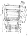
- Fig. 5 a table with the full set of dimensions of the exemplary corrugated horn, shown in Figs. 3 and 4 , is illustrated.
- the signal can be altered such that it is composed of the HE 11 mode and a number of additional, higher-order modes. With the higher-order modes in the horn aperture, more co-polarized power within the predetermined angle of a cone can be radiated.
- the optimal mode-mix depends on the desired amount of the co-polarized power within a predetermined solid angle of the cone and the horn aperture diameter.
- the radial corrugations provide effective control over the radiation patterns of a plurality of signals comprising a plurality of communication frequency bands.
- the throat section 110 of the horn converts the dominant (TE 11 ) mode of the feeding circular waveguide to the substantially pure HE 11 mode.
- TE 11 the dominant
- the throat section 110 of the horn converts the dominant (TE 11 ) mode of the feeding circular waveguide to the substantially pure HE 11 mode.
- the arrangement of corrugations forming the horn flare section widens, it becomes possible to excite higher-order field modes: the bigger the flare-section diameter, the higher the order of the field modes that can be excited and propagated toward the horn aperture, i.e., individual higher-order modes are excited at different locations along the horn length.
- the profile of horn corrugations can be specially designed or tuned to excite the higher-order modes, in addition to the HE 11 mode, that increase to a desired level the co-polarized power radiated within the solid angle of the cone subtended by the aperture (e.g., of a lens or reflector) that the horn illuminates, while providing a desired aperture-edge illumination taper, thus also a desired secondary-pattern sidelobe control.
- the aperture e.g., of a lens or reflector
- the corrugations in the horn flare section are dimensioned so that the higher-order modes required to achieve the desired effect are excited with the needed amplitudes and phases and that the corrugations that follow support the excited modes, so that the modes can propagate to the horn aperture.
- Bound states of electromagnetic energy anywhere within the horn over the operating frequency band(s) of the horn are avoided.
- the bound states are narrowband by nature and greatly disturb the input impedance and radiation patterns of the horn at the affected frequencies.
- both horns have the same input waveguide diameter (11.2 mm), the same electrical aperture diameter (27.3 mm) and the same aperture-edge illumination tapers at 41 degrees (14.8 dB at 20.2 GHz and 25.3 dB at 30.0 GHz), whereby the aperture-edge illumination taper at 41 degrees is the difference between the horn power gain at 0 degrees and 41 degrees, referring to the far-field radiation pattern plots 21 and 31 in Figs. 7 and 8 , respectively, as it would be obvious to anyone having ordinary skill in the art.
- FIG. 7 there is shown the far-field radiation pattern plot 21 of co-polarized radiation 23 of the conventional corrugated horn of Fig. 1 at 20.2 GHz and co-polarized radiation 22 of the exemplary corrugated horn in accordance with the principles of the present invention of Figs. 3 and 4 at 20.2 GHz.
- the horns are used to illuminate a circular aperture 4 with a conical half-angle 5 of 41 degrees, such as that of a reflector 3 in Fig.
- the radiation patterns of the two horns are substantially identical: both horns yield the same power gain (14.24 dBi) at 0 degrees, the same aperture-edge illumination taper (14.8 dB) at 41 degrees and radiate the same amount of co-polarized power toward the aperture, whereby the amount of radiated co-polarized power is proportional to the respective areas, in the 0-41 degree angular range, under the radiation pattern plots 22 and 23.
- Fig. 8 there is shown the far-field radiation pattern plot 31 of co-polarized radiation 33 of the conventional corrugated horn of Fig. 1 at 30.0 GHz and co-polarized radiation 32 of the exemplary corrugated horn in accordance with the principles of the present invention of Figs. 3 and 4 at 30.0 GHz.
- the horns are used to illuminate a circular aperture 4 with a conical half-angle 5 of 41 degrees, such as that of a reflector 3 in Fig. 6 , both horns yield the same aperture-edge illumination taper (25.3 dB).
- the power gain (16.56 dBi) at 0 degrees of the exemplary corrugated horn in accordance with the principles of the present invention is actually lower than that (17.77 dBi) of the conventional corrugated horn, meaning the exemplary corrugated horn in accordance with the principles of the present invention has a lower aperture efficiency than the conventional corrugated horn.
- the area from 0 to 41 degrees under the radiation pattern plot 32 (upon gain conversion from dB's to absolute values) of the exemplary corrugated horn in accordance with the principles of the present invention is by 18 percent larger than the area from 0 to 41 degrees under the radiation pattern plot 33 (upon gain conversion from dB's to absolute values) of the conventional corrugated horn.
- a circular aperture 4 with a conical half-angle 5 of 41 degrees, such as that of a reflector 3 in Fig. 6 captures more co-polarized power when illuminated by the exemplary corrugated horn in accordance with the principles of the present invention than when illuminated by the conventional corrugated horn.
- the increased co-polarized power captured by the aperture when illuminated by the exemplary corrugated horn in accordance with the principles of the present invention in turn, translates to a higher peak co-polarized power gain of the illuminated aperture - for example, when the exemplary corrugated horn in accordance with the principles of the present invention of Figs.
- the peak co-polarized power gain of the antenna system is by 0.7 dB higher than when the same displaced-axis Gregorian reflector configuration is illuminated by the conventional corrugated horn of Fig. 1 . It is in this end effect of providing a higher secondary-pattern peak power gain while maintaining a desired secondary-pattern sidelobe control where the principal utility of the present invention rests.
- the Kung et al. and Parrikar et al. references disclose corrugated horns with higher aperture efficiency - therefore also higher power gain at 0 degrees - so as to respectively achieve a flat-top beam and lower sidelobes of secondary radiation patterns produced by the reflector configuration that the corrugated horns illuminate.
- the present invention describes a corrugated horn with a higher amount of co-polarized power radiated within the solid angle of the cone subtended by the illuminated reflector configuration in order to achieve a higher power gain at 0 degrees of the reflector configuration (i.e., a higher power gain at 0 degrees of the secondary radiation pattern), not that of the horn itself.
- the present horn itself has a lower power gain at 0 degrees than the conventional corrugated horn.
- the desired effect that the present invention yields is achieved partly by reducing the power gain of the horn at 0 degrees, whereby part of the co-polarized power that the conventional corrugated horn radiates in the vicinity of 0 degrees is in the present invention redistributed further away from 0 degrees, closer to the imaginary surface of the cone subtended by the illuminated aperture, as the far-field radiation pattern plot 31 of Fig. 8 shows.
- a second contribution to the desired effect may come from redistributing the power from co-polarized far-out sidelobes of the conventional corrugated horn to the angular range of the cone subtended by the illuminated aperture - that effect is also apparent in the far-field radiation pattern plot 31 of Fig. 8 .
- the conventional corrugated horn achieves remarkably low cross-polarization (with the maximum of cross-polarized radiation 40 dB plus below the maximum of co-polarized radiation), this level of polarization purity is not always necessary in practical applications.
- the suppression of cross-polarized radiation in the designed-for operating frequency bands can be balanced as needed and traded against the desired effect of increasing the co-polarized power radiated within the solid angle of a cone.
- the present invention allows to reduce the drift of the phase-center position over the operating frequency band(s).
- the phase center of the conventional corrugated horn of Fig. 1 delimits the locus of 8.6 mm in overall length (2.5-3.1 mm and 10.2-11.1 mm behind the horn aperture in the 20.2-21.2 GHz and 30.0-31.0 GHz bands, respectively)
- the phase center of the exemplary corrugated horn in accordance with the principles of the present invention of Fig. 3 and 4 delimits the locus of only 2.6 mm in overall length (1.1-2.3 mm behind the horn aperture in the 20.2-21.2 GHz band and 0.5 mm behind to 0.3 mm in front of the horn aperture in the 30.0-31.0 GHz band).
- the shorter length of the locus reduces the degree of antenna performance compromise that must be made in determining one optimal feed location - i.e., the overall least-damaging amount of defocusing - in the reflector/lens system that the horn illuminates, such as that shown in Fig. 6 .
Landscapes
- Waveguide Aerials (AREA)
- Aerials With Secondary Devices (AREA)
- Variable-Direction Aerials And Aerial Arrays (AREA)
Abstract
A feed horn (1) for transmitting and receiving signals comprises a throat section (110) for converting the TE11 mode to the HE11 mode, an aperture section (130) opposite to the throat section (110), and a multiple-corrugation transition section (120) connected to the throat section (110). The transition section (120) comprises a plurality of radial corrugations (121) that substantially widen the feed horn (1) from the throat section (110) toward the aperture section (130) wherein the throat section (110), the aperture section (130) and the transition section (120) have a same axis of symmetry. The profile of horn corrugations (111, 121) is specially designed or tuned to maximize the amount of power captured by an illuminated reflector or lens and avoid excitation of bound states of electromagnetic energy in the horn (1) over the operating frequency band(s) of the horn. As a result of the increased captured power, for a given reflector- or lens-edge illumination taper, thereby also sidelobe-suppression level, the peak power gain of the reflector or lens increases while the peak power gain of the illuminating horn itself decreases. The present radially-corrugated horn may be used in wide- or multi-band reflector or lens antennas that would benefit from reduced frequency dependence of radiation patterns of the conventional radially-corrugated horn.
Description
- The present invention relates to horn antennas and, more particularly, to radially-corrugated horns for illumination of reflector and lens antennas.
- A conventional corrugated horn with radial corrugations, such as the one described in
US Patent 4,472,721 granted on 18 September 1984 to Mörz et al . and the ones in "Characteristics of a broadband microwave corrugated feed: A comparison between theory and experiment" (Bell System Technical Journal, vol. 56, no. 6, pp. 869-889, July-August 1977) by Dragone or described in the publication "Design of corrugated horns: a primer" (IEEE Antennas and Propagation Magazine, vol. 47, , consists of a corrugated mode converter and a corrugated flare section. In the case of a circular cross-section of the corrugated horn, the mode converter converts the dominant (TE11) mode of the feeding circular waveguide to the substantially pure HE11 mode. The flare section then supports the generated HE11 mode as it propagates from the mode converter to the horn aperture. While the mode converter can be one of several types - such as the variable-depth-slot, ring-loaded-slot or variable-pitch-to-width-slot - the flare section employs corrugations with substantially constant widths, depths and spacings. - More recent prior-art patents relating to corrugated horns with radial corrugations refer to high aperture efficiency, thus also high power gain, of the horns. For example,
US Patent Application Publication 2002/0167453 A1 by Kung et al., published on 14 November 2002 , describes one such high-aperture-efficiency horn that yields a flat-top secondary-pattern beam when used to illuminate a reflector.US Patent 6,522,306 B1 granted on 18 February 2003 to Parrikar et al . describes a hybrid horn, consisting of corrugations and a smooth-walled flare section, producing high power gain and lower secondary-pattern sidelobes. - Corrugated horns are wideband devices. They can be designed for supreme co-polarized beam integrity, low cross-polarization and good impedance match over one wide frequency band or several sub-bands contained within that wide band. However, when the horn flare angles are relatively small and the corrugations are machined radially (i.e., perpendicularly to the horn central axis), as opposed to perpendicularly to the metallic walls of the horn flares, the horns' co-polarized radiation patterns are frequency dependent. This is illustrated in
Figs. 1 and2 where a conventionalcorrugated horn 1 depicted in a cross-section inFig. 1 yields the far-field radiation patterns 11 presented inFig. 2 . InFig. 1 , athroat section 110, constituting a TE11-to-HE11 mode converter, of thehorn 1 has in total fourcorrugations 111. Theflare section 120 comprises 13 corrugations and is connected to thethroat section 110. The diameter of thecorrugations 121 expands from the throat section towards thehorn aperture 130. InFig. 2 , theco-polarized pattern 13 at a higher frequency (30.0 GHz) features a power gain at 0 degrees higher than theco-polarized pattern 12 at a lower frequency (20.2 GHz); similarly, theco-polarized pattern 13 at a higher frequency has the beam (main lobe) narrower that theco-polarized pattern 12 at a lower frequency. When such a horn is employed to illuminate anaperture 4, e.g., of a lens orreflector 3 depicted inFig. 6 , the resulting secondary radiation patterns at the two frequencies are uneven - for example, a reflector/lens illuminated by a corrugated horn that was designed for optimal reflector/lens radiation performance at a lower frequency will exhibit suboptimal radiation performance at a higher frequency and vice versa. - It is therefore an object of the present invention to provide a radially-corrugated horn that obviates the above-noted disadvantage of the conventional radially-corrugated horn by eliminating or reducing frequency dependence of the horn's radiation patterns.
- The invention provides a feed horn for transmitting and receiving signals. The horn comprises a throat section for converting the TE11 mode to the HE11 mode, an aperture section opposite to the throat section, and a multiple-corrugation transition section connected to the throat section. The transition section has a plurality of radial corrugations that substantially widen the feed horn from the throat section toward the aperture section wherein the throat section, the aperture section and the transition section have a same axis of symmetry and wherein the plurality of corrugations are dimensioned relative to one another to alter the mode content of the signal so that the feed horn radiates more co-polarized power within a predetermined solid angle of a cone in at least one frequency band than the feed horn employing the substantially pure HE11 mode in its aperture and providing the same illumination taper at the same conical half-angle at the same frequencies.
- It has been found that by adjusting the geometrical dimensions of the corrugations of the horn's flare section the signal can be altered such that it is composed of the HE11 mode and a number of additional, higher-order modes. With the higher-order modes in the horn aperture, more co-polarized power within the predetermined angle of a cone can be radiated. The optimal mode-mix depends on the desired amount of the co-polarized power within a predetermined solid angle of the cone and the horn aperture diameter. As a result the radial corrugations provide effective control over the radiation patterns of a plurality of signals comprising a plurality of communication frequency bands.
- The throat section of the horn converts the dominant (TE11) mode of the feeding circular waveguide to the substantially pure HE11 mode. However, as the arrangement of corrugations forming the horn flare section widens, it becomes possible to excite higher-order field modes: the bigger the flare-section diameter, the higher the order of the field modes that can be excited and propagated toward the horn aperture, i.e., individual higher-order modes are excited at different locations along the horn length. Using theoretical analysis and/or mathematical optimization, the profile of horn corrugations is specially designed or tuned to excite the higher-order modes, in addition to the HE11 mode, that increase to a desired level the co-polarized power radiated within the solid angle of the cone subtended by the aperture (e.g., of a lens or reflector) that the horn illuminates, while providing a desired aperture-edge illumination taper, thus also a desired secondary-pattern sidelobe control. The corrugations in the horn flare section are dimensioned so that the higher-order modes required to achieve the desired effect are excited with the needed amplitudes and phases and that the corrugations that follow support the excited modes, so that the modes can propagate to the horn aperture. Bound states of electromagnetic energy anywhere within the horn over the operating frequency band(s) of the horn are avoided. The bound states are narrowband by nature and greatly disturb the input impedance and radiation patterns of the horn at the affected frequencies.
- There is no one universally optimal composition of field modes, described by the amplitudes and phases of the individual modes, in the aperture of the horn in accordance with the principles of the present invention. In any application, the optimal modal composition primarily depends on the horn aperture diameter, the desired aperture-edge illumination taper and the desired amount of the co-polarized power within a predetermined solid angle of a cone. Other performance parameters, such as the maximal acceptable level of cross-polarization, may also have to be factored into the determination of the optimal modal composition.
- There is no single feature (shape or arrangement of corrugations) that makes the horn in accordance with the principles of the present invention achieve the increase of captured co-polarized power. The horn corrugations strongly interact with one another, whereby the interactions (mutual couplings) extend beyond immediately adjacent corrugations. Consequently, it is the global action of the entire flare section, with a multitude of complex mutual couplings within, that achieves the described effect.
- The present corrugated horn retains the high polarization purity and the wideband input-impedance and radiation-pattern characteristics of the conventional corrugated horn. In addition, it significantly reduces the position drift of the conventional corrugated horn's phase center over the operating frequency band(s).
- The corrugated horn does not feature high aperture efficiency (thus also high power gain), which is beneficial for multiple-beam antennas, as disclosed in the Kung et al. and Parrikar et al. references. Instead, by increasing the co-polarized power captured by the illuminated aperture, the horn is more advantageous in single-beam antennas.
- According to a further improved embodiment, the feed horn further comprises an input-impedance matching section coupled between the feed horn and a feeding waveguide, said section matching the input impedance of the feed horn through non-reflective direct signal propagation in the at least one operating frequency band.
- According to a further improved embodiment, the feed horn is free of bound states of electromagnetic energy within the at least one operating frequency band.
- According to a further improved embodiment, the overall locus of feed horn's phase center positions over the at least one operating frequency band spans a shorter distance than that of the horn employing the substantially pure HE11 mode in its aperture.
- According to a further improved embodiment, the feed horn is adapted to produce low cross-polarization in at least one operating frequency band.
- The invention has a number of advantages:
- It is an advantage of the invention that the radially-corrugated horn illuminates an aperture in such a way that the illuminated aperture captures more co-polarized power than when illuminated by the conventional radially-corrugated horn providing the same aperture-edge illumination taper.
- Furthermore, the radially-corrugated horn enables more control over the peak co-polarized radiation gain values at lower and/or higher frequencies than the conventional radially-corrugated horn.
- Yet another advantage of the present invention is that the radially-corrugated horn enables more control over the co-polarized radiation beam (main lobe) shape at lower and/or higher frequencies than the conventional radially-corrugated horn.
- Still another advantage of the present invention is that the radially-corrugated horn provides excellent polarization purity.
- Furthermore, the radially-corrugated horn reduces position drift of the horn's phase center over the operating frequency band(s).
- Last, the radially-corrugated horn has an excellent input-impedance match.
- The invention will be described in more detail by means of the accompanying drawings. In the annexed drawings, like reference characters indicate like elements throughout.
-
Figure 1 illustrates a longitudinal cross-sectional view along the central axis through a conventional corrugated horn with radial corrugations; -
Figure 2 shows a plot of far-field co-polarized radiation patterns of a conventional corrugated horn ofFig. 1 - solid line: 20.2 GHz; dashed line: 30.0 GHz; -
Figure 3 shows a perspective view of an exemplary corrugated horn in accordance with the principles of the present invention; -
Figure 4 is the longitudinal cross-sectional view along the central axis through an exemplary corrugated horn in accordance with the principles of the present invention; -
Figure 5 shows a table with the full set of dimensions of the exemplary corrugated horn, shown inFigs. 3 and4 ; -
Figure 6 is a perspective view of a horn illuminating a reflector; -
Figure 7 is a plot of far-field co-polarized radiation patterns of corrugated horns at 20.2 GHz - solid line: the exemplary corrugated horn in accordance with the principles of the present invention ofFigs. 3 and4 ; dashed line: the conventional corrugated horn ofFig. 1 ; and -
Figure 8 is a plot of far-field co-polarized radiation patterns of corrugated horns at 30.0 GHz - solid line: the exemplary corrugated horn in accordance with the principles of the present invention ofFigs. 3 and4 ; dashed line: the conventional corrugated horn ofFig. 1 . - With reference to the annexed drawings, the preferred embodiment of the present invention will be herein described for indicative purpose and by no means as of limitation.
-
Fig. 3 shows afeed horn 1 for transmitting and receiving signals according to the invention in a perspective view.Fig. 4 shows thisfeed horn 1 in a cross-sectional view along a central axis. Thefeed horn 1 comprises athroat section 110 having fourcorrugations 111 for converting the TE11 mode to the HE11 mode. Anaperture section 130 is provided opposite to thethroat section 110. A multiple-corrugation transition section 120 representing the horn's flare section is connected to thethroat section 110. Theflare section 120 has a number of 14 ofradial corrugations 121 that substantially widen thefeed horn 1 from thethroat section 110 toward theaperture section 130. Thethroat section 110, theaperture section 130 and theflare section 120 have a same axis of symmetry (not shown inFigs. 3 and4 ). Thecorrugations 121 of theflare section 120 are dimensioned relative to one another to alter the mode content of the signal so that thefeed horn 1 radiates more co-polarized power within a predetermined solid angle of a cone in at least one frequency band than the feed horn employing the substantially pure HE11 mode in its aperture and providing the same illumination taper at the same conical half-angle at the same frequencies. - This behavior is achieved solely by adjusting the geometrical dimensions of the corrugations of the horn's flare section. In
Fig. 5 a table with the full set of dimensions of the exemplary corrugated horn, shown inFigs. 3 and4 , is illustrated. The cylindrical section number of this table is denoted with CNi, where i = 1 to 37, inFig. 4 . In a feed horn as described, the signal can be altered such that it is composed of the HE11 mode and a number of additional, higher-order modes. With the higher-order modes in the horn aperture, more co-polarized power within the predetermined angle of a cone can be radiated. The optimal mode-mix depends on the desired amount of the co-polarized power within a predetermined solid angle of the cone and the horn aperture diameter. As a result, the radial corrugations provide effective control over the radiation patterns of a plurality of signals comprising a plurality of communication frequency bands. - The
throat section 110 of the horn converts the dominant (TE11) mode of the feeding circular waveguide to the substantially pure HE11 mode. However, as the arrangement of corrugations forming the horn flare section widens, it becomes possible to excite higher-order field modes: the bigger the flare-section diameter, the higher the order of the field modes that can be excited and propagated toward the horn aperture, i.e., individual higher-order modes are excited at different locations along the horn length. - Using theoretical analysis and/or mathematical optimization, the profile of horn corrugations can be specially designed or tuned to excite the higher-order modes, in addition to the HE11 mode, that increase to a desired level the co-polarized power radiated within the solid angle of the cone subtended by the aperture (e.g., of a lens or reflector) that the horn illuminates, while providing a desired aperture-edge illumination taper, thus also a desired secondary-pattern sidelobe control.
- The corrugations in the horn flare section are dimensioned so that the higher-order modes required to achieve the desired effect are excited with the needed amplitudes and phases and that the corrugations that follow support the excited modes, so that the modes can propagate to the horn aperture. Bound states of electromagnetic energy anywhere within the horn over the operating frequency band(s) of the horn are avoided. The bound states are narrowband by nature and greatly disturb the input impedance and radiation patterns of the horn at the affected frequencies.
- Advantages of the present invention with respect to the conventional radially-corrugated horn will be demonstrated on a like-for-like comparison of horns designed for the same operating frequency bands (20.2-21.2 GHz and 30.0-31.0 GHz): both horns have the same input waveguide diameter (11.2 mm), the same electrical aperture diameter (27.3 mm) and the same aperture-edge illumination tapers at 41 degrees (14.8 dB at 20.2 GHz and 25.3 dB at 30.0 GHz), whereby the aperture-edge illumination taper at 41 degrees is the difference between the horn power gain at 0 degrees and 41 degrees, referring to the far-field radiation pattern plots 21 and 31 in
Figs. 7 and8 , respectively, as it would be obvious to anyone having ordinary skill in the art. - Referring to
Fig. 7 , there is shown the far-fieldradiation pattern plot 21 ofco-polarized radiation 23 of the conventional corrugated horn ofFig. 1 at 20.2 GHz andco-polarized radiation 22 of the exemplary corrugated horn in accordance with the principles of the present invention ofFigs. 3 and4 at 20.2 GHz. When the horns are used to illuminate acircular aperture 4 with a conical half-angle 5 of 41 degrees, such as that of areflector 3 inFig. 6 , the radiation patterns of the two horns are substantially identical: both horns yield the same power gain (14.24 dBi) at 0 degrees, the same aperture-edge illumination taper (14.8 dB) at 41 degrees and radiate the same amount of co-polarized power toward the aperture, whereby the amount of radiated co-polarized power is proportional to the respective areas, in the 0-41 degree angular range, under the radiation pattern plots 22 and 23. - Referring to
Fig. 8 , there is shown the far-fieldradiation pattern plot 31 ofco-polarized radiation 33 of the conventional corrugated horn ofFig. 1 at 30.0 GHz andco-polarized radiation 32 of the exemplary corrugated horn in accordance with the principles of the present invention ofFigs. 3 and4 at 30.0 GHz. When the horns are used to illuminate acircular aperture 4 with a conical half-angle 5 of 41 degrees, such as that of areflector 3 inFig. 6 , both horns yield the same aperture-edge illumination taper (25.3 dB). The power gain (16.56 dBi) at 0 degrees of the exemplary corrugated horn in accordance with the principles of the present invention is actually lower than that (17.77 dBi) of the conventional corrugated horn, meaning the exemplary corrugated horn in accordance with the principles of the present invention has a lower aperture efficiency than the conventional corrugated horn. However, the area from 0 to 41 degrees under the radiation pattern plot 32 (upon gain conversion from dB's to absolute values) of the exemplary corrugated horn in accordance with the principles of the present invention is by 18 percent larger than the area from 0 to 41 degrees under the radiation pattern plot 33 (upon gain conversion from dB's to absolute values) of the conventional corrugated horn. This means acircular aperture 4 with a conical half-angle 5 of 41 degrees, such as that of areflector 3 inFig. 6 , captures more co-polarized power when illuminated by the exemplary corrugated horn in accordance with the principles of the present invention than when illuminated by the conventional corrugated horn. The increased co-polarized power captured by the aperture when illuminated by the exemplary corrugated horn in accordance with the principles of the present invention, in turn, translates to a higher peak co-polarized power gain of the illuminated aperture - for example, when the exemplary corrugated horn in accordance with the principles of the present invention ofFigs. 3 and4 is used to illuminate a displaced-axis Gregorian reflector configuration whose subreflector has the conical half-angle of 41 degrees and the main reflector has the diameter of 1 m, the peak co-polarized power gain of the antenna system is by 0.7 dB higher than when the same displaced-axis Gregorian reflector configuration is illuminated by the conventional corrugated horn ofFig. 1 . It is in this end effect of providing a higher secondary-pattern peak power gain while maintaining a desired secondary-pattern sidelobe control where the principal utility of the present invention rests. - Although the effect of increased captured co-polarized power when an aperture is illuminated by the preferred embodiment of the present invention has been demonstrated in only one of the two bands that the preferred embodiment of the present invention was designed for, it is to be understood that the disclosure has been made by way of example only and that the present invention is not limited to the effect of increased captured co-polarized power in one band only; rather the effect of increased captured co-polarized power can be achieved in one or more frequency bands, and the amount of increased captured co-polarized power in the frequency bands can be controlled and balanced one against another with proper tuning of the horn profile.
- In order to re-emphasize the principal differences between the prior-art patents and the present invention, the Kung et al. and Parrikar et al. references disclose corrugated horns with higher aperture efficiency - therefore also higher power gain at 0 degrees - so as to respectively achieve a flat-top beam and lower sidelobes of secondary radiation patterns produced by the reflector configuration that the corrugated horns illuminate. In contrast, the present invention describes a corrugated horn with a higher amount of co-polarized power radiated within the solid angle of the cone subtended by the illuminated reflector configuration in order to achieve a higher power gain at 0 degrees of the reflector configuration (i.e., a higher power gain at 0 degrees of the secondary radiation pattern), not that of the horn itself. As is shown in the far-field
radiation pattern plot 31 ofFig. 8 , the present horn itself has a lower power gain at 0 degrees than the conventional corrugated horn. - As a matter of fact, the desired effect that the present invention yields is achieved partly by reducing the power gain of the horn at 0 degrees, whereby part of the co-polarized power that the conventional corrugated horn radiates in the vicinity of 0 degrees is in the present invention redistributed further away from 0 degrees, closer to the imaginary surface of the cone subtended by the illuminated aperture, as the far-field
radiation pattern plot 31 ofFig. 8 shows. A second contribution to the desired effect may come from redistributing the power from co-polarized far-out sidelobes of the conventional corrugated horn to the angular range of the cone subtended by the illuminated aperture - that effect is also apparent in the far-fieldradiation pattern plot 31 ofFig. 8 . - While the conventional corrugated horn achieves remarkably low cross-polarization (with the maximum of cross-polarized radiation 40 dB plus below the maximum of co-polarized radiation), this level of polarization purity is not always necessary in practical applications. In the present invention, the suppression of cross-polarized radiation in the designed-for operating frequency bands can be balanced as needed and traded against the desired effect of increasing the co-polarized power radiated within the solid angle of a cone.
- It is also noteworthy the present invention allows to reduce the drift of the phase-center position over the operating frequency band(s). For example, while the phase center of the conventional corrugated horn of
Fig. 1 delimits the locus of 8.6 mm in overall length (2.5-3.1 mm and 10.2-11.1 mm behind the horn aperture in the 20.2-21.2 GHz and 30.0-31.0 GHz bands, respectively), the phase center of the exemplary corrugated horn in accordance with the principles of the present invention ofFig. 3 and4 delimits the locus of only 2.6 mm in overall length (1.1-2.3 mm behind the horn aperture in the 20.2-21.2 GHz band and 0.5 mm behind to 0.3 mm in front of the horn aperture in the 30.0-31.0 GHz band). The shorter length of the locus, in turn, reduces the degree of antenna performance compromise that must be made in determining one optimal feed location - i.e., the overall least-damaging amount of defocusing - in the reflector/lens system that the horn illuminates, such as that shown inFig. 6 .
Claims (9)
- A feed horn (1) for transmitting and receiving signals, comprising a throat section (110) for converting the TE11 mode to the HE11 mode, an aperture section (130) opposite to the throat section (110), and a multiple-corrugation transition section (120) connected to the throat section (110), the transition section (120) having a plurality of radial corrugations (121) that substantially widen the feed horn (1) from the throat section (110) toward the aperture section (130) wherein the throat section (110), the aperture section (130) and the transition section (120) have a same axis of symmetry and wherein the plurality of corrugations (111, 121) are dimensioned relative to one another to alter the mode content of the signal so that the feed horn (1) radiates more co-polarized power within a predetermined solid angle of a cone in at least one frequency band than the feed horn employing the substantially pure HE11 mode in its aperture and providing the same illumination taper at the same conical half-angle at the same frequencies.
- The feed horn according to claim 1 further comprising an input-impedance matching section coupled between the feed horn (1) and a feeding waveguide, said section matching the input impedance of the feed horn through non-reflective direct signal propagation in the at least one operating frequency band.
- The feed horn according to claim 1 or 2, wherein the feed horn (1) is free of bound states of electromagnetic energy within the at least one operating frequency band.
- The feed horn according to one of the preceding claims, wherein the overall
locus of feed horn's phase center positions over the at least one operating frequency band spans a shorter distance than that of the horn employing the substantially pure HE11 mode in its aperture. - The feed horn according to one of the preceding claims, wherein the feed horn is adapted to produce low cross-polarization in at least one operating frequency band.
- A method for forming a feed horn (1), said method comprising the steps of:- providing a throat section (110);- providing an aperture section (130) opposite to the throat section (110); and- providing a multiple-corrugation transition section (120) connected to the throat section (110) so that the transition section (120) includes a plurality of radial corrugations (121) that substantially widen the feed horn (1) from the throat section (110) toward the aperture section (130), said multiple corrugations being dimensioned relative to one another to alter the mode content of the signal so that the overall feed horn (1) radiates more co-polarized power within a predetermined solid angle of a cone in at least one frequency band than the horn employing the substantially pure HE11 mode in its aperture and providing the same illumination taper at the same conical half-angle at the same frequencies.
- The method according to claim 6, wherein the feed horn (1) is free of bound states of electromagnetic energy within the at least one operating frequency band.
- The method according to claim 6 or 7, wherein the overall locus of feed horn's phase center positions over the at least one operating frequency band spans a shorter distance than that of the horn employing the substantially pure HE11 mode in its aperture and providing the same illumination taper at the same conical half-angle at the same frequencies.
- The method according to one of claims 6 to 8, wherein the feed horn (1) produces low cross-polarization in the at least one operating frequency band.
Priority Applications (3)
| Application Number | Priority Date | Filing Date | Title |
|---|---|---|---|
| EP11004875A EP2535982A1 (en) | 2011-06-15 | 2011-06-15 | Corrugated horn for increased power captured by illuminated aperture |
| US13/492,178 US20120319910A1 (en) | 2011-06-15 | 2012-06-08 | Corrugated horn for increased power captured by illuminated aperture |
| JP2012135006A JP2013005444A (en) | 2011-06-15 | 2012-06-14 | Feed horn having corrugations for increasing radiation power captured by aperture to be illuminated |
Applications Claiming Priority (1)
| Application Number | Priority Date | Filing Date | Title |
|---|---|---|---|
| EP11004875A EP2535982A1 (en) | 2011-06-15 | 2011-06-15 | Corrugated horn for increased power captured by illuminated aperture |
Publications (1)
| Publication Number | Publication Date |
|---|---|
| EP2535982A1 true EP2535982A1 (en) | 2012-12-19 |
Family
ID=44801260
Family Applications (1)
| Application Number | Title | Priority Date | Filing Date |
|---|---|---|---|
| EP11004875A Withdrawn EP2535982A1 (en) | 2011-06-15 | 2011-06-15 | Corrugated horn for increased power captured by illuminated aperture |
Country Status (3)
| Country | Link |
|---|---|
| US (1) | US20120319910A1 (en) |
| EP (1) | EP2535982A1 (en) |
| JP (1) | JP2013005444A (en) |
Cited By (1)
| Publication number | Priority date | Publication date | Assignee | Title |
|---|---|---|---|---|
| CN109244677A (en) * | 2018-11-13 | 2019-01-18 | 中国科学院国家天文台 | A kind of oblique angle coaxial corrugated horn structure |
Families Citing this family (6)
| Publication number | Priority date | Publication date | Assignee | Title |
|---|---|---|---|---|
| CN104682012B (en) * | 2015-03-14 | 2018-04-17 | 西安电子科技大学 | The low scattering angle reflecting surface of high-gain of gradual change ripple loading |
| US9606425B2 (en) * | 2015-06-19 | 2017-03-28 | Canon Kabushiki Kaisha | Imaging optical system, optical apparatus and image projection apparatus |
| CN107634344B (en) * | 2017-09-22 | 2020-03-17 | 上海航天测控通信研究所 | Small-opening-angle horn shaped antenna with axial corrugated transition section |
| CN110596570B (en) * | 2019-08-30 | 2021-09-24 | 电子科技大学 | A confocal waveguide high frequency circuit test system |
| CN111799546B (en) * | 2020-05-26 | 2023-04-28 | 安徽四创电子股份有限公司 | Millimeter wave broadband corrugated horn and manufacturing method thereof |
| US12237576B2 (en) * | 2020-07-09 | 2025-02-25 | Macdonald, Dettwiler And Associates Corporation | Single-piece corrugated component of an antenna and method of manufacture thereof |
Citations (4)
| Publication number | Priority date | Publication date | Assignee | Title |
|---|---|---|---|---|
| US4472721A (en) | 1981-03-13 | 1984-09-18 | Licentia Patent-Verwaltungs-G.M.B.H. | Broadband corrugated horn radiator |
| US20020167453A1 (en) | 2001-05-11 | 2002-11-14 | Kung Pamela H. | High efficiency corrugated horn and flat top multiple beam antenna |
| US6522306B1 (en) | 2001-10-19 | 2003-02-18 | Space Systems/Loral, Inc. | Hybrid horn for dual Ka-band communications |
| EP1508939A1 (en) * | 2002-05-24 | 2005-02-23 | Universidad Publica De Navarra | Horn antenna combining horizontal and vertical ridges |
Family Cites Families (4)
| Publication number | Priority date | Publication date | Assignee | Title |
|---|---|---|---|---|
| US6396453B2 (en) * | 2000-04-20 | 2002-05-28 | Ems Technologies Canada, Ltd. | High performance multimode horn |
| US7002528B2 (en) * | 2002-02-20 | 2006-02-21 | Prodelin Corporation | Circularly polarized receive/transmit elliptic feed horn assembly for satellite communications |
| US8077103B1 (en) * | 2007-07-07 | 2011-12-13 | The United States Of America As Represented By The Administrator Of The National Aeronautics And Space Administration | Cup waveguide antenna with integrated polarizer and OMT |
| US7755557B2 (en) * | 2007-10-31 | 2010-07-13 | Raven Antenna Systems Inc. | Cross-polar compensating feed horn and method of manufacture |
-
2011
- 2011-06-15 EP EP11004875A patent/EP2535982A1/en not_active Withdrawn
-
2012
- 2012-06-08 US US13/492,178 patent/US20120319910A1/en not_active Abandoned
- 2012-06-14 JP JP2012135006A patent/JP2013005444A/en active Pending
Patent Citations (4)
| Publication number | Priority date | Publication date | Assignee | Title |
|---|---|---|---|---|
| US4472721A (en) | 1981-03-13 | 1984-09-18 | Licentia Patent-Verwaltungs-G.M.B.H. | Broadband corrugated horn radiator |
| US20020167453A1 (en) | 2001-05-11 | 2002-11-14 | Kung Pamela H. | High efficiency corrugated horn and flat top multiple beam antenna |
| US6522306B1 (en) | 2001-10-19 | 2003-02-18 | Space Systems/Loral, Inc. | Hybrid horn for dual Ka-band communications |
| EP1508939A1 (en) * | 2002-05-24 | 2005-02-23 | Universidad Publica De Navarra | Horn antenna combining horizontal and vertical ridges |
Non-Patent Citations (4)
| Title |
|---|
| BELL SYSTEM TECHNICAL JOURNAL, vol. 56, no. 6, July 1977 (1977-07-01), pages 869 - 889 |
| CARLOS DEL RIO BOCIO: "Modern Corrugated Horn Antennas", 1 July 2003 (2003-07-01), Navarra, XP055010702, Retrieved from the Internet <URL:http://antenas.unavarra.es/Publicaciones/Images/Tesis3_1.pdf> [retrieved on 20111028] * |
| GRANET, JAMES: "Design of corrugated horns: a primer", IEEE ANTENNAS AND PROPAGATION MAGAZINE, vol. 47, no. 2, April 2005 (2005-04-01), pages 76 - 84 |
| PAUL A S CRUICKSHANK ET AL: "Reducing standing waves in quasi-optical systems by optimal feedhorn design", INFRARED AND MILLIMETER WAVES, 2007 AND THE 2007 15TH INTERNATIONAL CONFERENCE ON TERAHERTZ ELECTRONICS. IRMMW-THZ. JOINT 32ND INTERNATIONAL CONFERENCE ON, IEEE, PISCATAWAY, NJ, USA, 2 September 2007 (2007-09-02), pages 941 - 942, XP031249904, ISBN: 978-1-4244-1438-3 * |
Cited By (2)
| Publication number | Priority date | Publication date | Assignee | Title |
|---|---|---|---|---|
| CN109244677A (en) * | 2018-11-13 | 2019-01-18 | 中国科学院国家天文台 | A kind of oblique angle coaxial corrugated horn structure |
| CN109244677B (en) * | 2018-11-13 | 2023-10-17 | 中国科学院国家天文台 | Oblique coaxial corrugated horn structure |
Also Published As
| Publication number | Publication date |
|---|---|
| US20120319910A1 (en) | 2012-12-20 |
| JP2013005444A (en) | 2013-01-07 |
Similar Documents
| Publication | Publication Date | Title |
|---|---|---|
| EP1152484B1 (en) | High performance multimode horn | |
| US6724349B1 (en) | Splashplate antenna system with improved waveguide and splashplate (sub-reflector) designs | |
| US7187340B2 (en) | Simultaneous multi-band ring focus reflector antenna-broadband feed | |
| US6967627B2 (en) | High radiation efficient dual band feed horn | |
| US9318810B2 (en) | Ring focus antenna | |
| US20120319910A1 (en) | Corrugated horn for increased power captured by illuminated aperture | |
| AU2012331250B2 (en) | Reflector antenna including dual band splashplate support | |
| CN104488139A (en) | Low sidelobe reflector antenna with shield | |
| JP2000299605A (en) | Horn antenna operated in plural separated frequencies | |
| EP1672739A1 (en) | High performance multimode horn for communications and tracking | |
| EP1041672A1 (en) | Multimode, multi-step antenna feed horn | |
| US7463207B1 (en) | High-efficiency horns for an antenna system | |
| EP3847716B1 (en) | Antenna feed chain | |
| CA1224563A (en) | Paraboloid reflector antenna feed having a flange with tapered corrugations | |
| CN107069225B (en) | Cassegrain antenna feed source structure and Cassegrain antenna | |
| KR101032190B1 (en) | Dielectric Load Horn and Dual Reflector Antenna Using the Same | |
| CA2486792A1 (en) | Horn antenna combining horizontal and vertical ridges | |
| US20020126063A1 (en) | Rectangular paraboloid truncation wall | |
| US8665165B1 (en) | Broad beam waveguide feed and reflector antenna employing same | |
| Patel | Designing Cassegrainian reflector and feed system for a cloud radar: The Minimum Blockage Condition | |
| EP1628361A1 (en) | Antenna reflector structure |
Legal Events
| Date | Code | Title | Description |
|---|---|---|---|
| PUAI | Public reference made under article 153(3) epc to a published international application that has entered the european phase |
Free format text: ORIGINAL CODE: 0009012 |
|
| AK | Designated contracting states |
Kind code of ref document: A1 Designated state(s): AL AT BE BG CH CY CZ DE DK EE ES FI FR GB GR HR HU IE IS IT LI LT LU LV MC MK MT NL NO PL PT RO RS SE SI SK SM TR |
|
| AX | Request for extension of the european patent |
Extension state: BA ME |
|
| 17P | Request for examination filed |
Effective date: 20130613 |
|
| 17Q | First examination report despatched |
Effective date: 20130712 |
|
| STAA | Information on the status of an ep patent application or granted ep patent |
Free format text: STATUS: THE APPLICATION IS DEEMED TO BE WITHDRAWN |
|
| 18D | Application deemed to be withdrawn |
Effective date: 20140123 |