EP2535869A2 - Apparatus and method for detecting posture of camera mounted on vehicle - Google Patents
Apparatus and method for detecting posture of camera mounted on vehicle Download PDFInfo
- Publication number
- EP2535869A2 EP2535869A2 EP12171485A EP12171485A EP2535869A2 EP 2535869 A2 EP2535869 A2 EP 2535869A2 EP 12171485 A EP12171485 A EP 12171485A EP 12171485 A EP12171485 A EP 12171485A EP 2535869 A2 EP2535869 A2 EP 2535869A2
- Authority
- EP
- European Patent Office
- Prior art keywords
- camera
- posture
- image
- vehicle
- basis
- Prior art date
- Legal status (The legal status is an assumption and is not a legal conclusion. Google has not performed a legal analysis and makes no representation as to the accuracy of the status listed.)
- Granted
Links
Images


Classifications
-
- G—PHYSICS
- G06—COMPUTING OR CALCULATING; COUNTING
- G06T—IMAGE DATA PROCESSING OR GENERATION, IN GENERAL
- G06T7/00—Image analysis
- G06T7/80—Analysis of captured images to determine intrinsic or extrinsic camera parameters, i.e. camera calibration
-
- G—PHYSICS
- G06—COMPUTING OR CALCULATING; COUNTING
- G06T—IMAGE DATA PROCESSING OR GENERATION, IN GENERAL
- G06T2207/00—Indexing scheme for image analysis or image enhancement
- G06T2207/30—Subject of image; Context of image processing
- G06T2207/30204—Marker
-
- G—PHYSICS
- G06—COMPUTING OR CALCULATING; COUNTING
- G06T—IMAGE DATA PROCESSING OR GENERATION, IN GENERAL
- G06T2207/00—Indexing scheme for image analysis or image enhancement
- G06T2207/30—Subject of image; Context of image processing
- G06T2207/30244—Camera pose
-
- G—PHYSICS
- G06—COMPUTING OR CALCULATING; COUNTING
- G06T—IMAGE DATA PROCESSING OR GENERATION, IN GENERAL
- G06T2207/00—Indexing scheme for image analysis or image enhancement
- G06T2207/30—Subject of image; Context of image processing
- G06T2207/30248—Vehicle exterior or interior
- G06T2207/30252—Vehicle exterior; Vicinity of vehicle
Definitions
- the present invention relates to an in-vehicle camera posture detecting apparatus and method for detecting an installation angle and the like of a camera that is mounted on a vehicle and captures an image of surroundings of the vehicle.
- the installation position and angle of the camera or each camera have to be accurately determined.
- the installation position and angle of a typical camera are often predetermined upon design of a system including the camera. Since an installation error is actually caused, calibration is performed after installation and the installation position and angle are then detected.
- a camera installation angle calculating method has been known by which the installation position and angle of a camera are detected on the basis of images of a calibration sheet captured through the camera, the calibration sheet being placed in a predetermined position near a vehicle and having a printed calibration pattern including a plurality of calibration marks (cf. JP 2010-183265 A , pp. 2-11, Figs. 1 to 23 , for example).
- the above-described method assumes that the calibration sheet is accurately placed in the predetermined position.
- the posture (position and angle) of the camera will fail to be accurately detected.
- the calibration sheet is placed on the ground at the rear of the vehicle such that the placed calibration sheet is aligned with one end of a rear bumper and an image of the calibration sheet is captured by the camera installed in the rear of the vehicle.
- the position of the calibration sheet is positioned in that manner, it is difficult to align the calibration sheet with the end of the rear bumper, since the rear bumper is spaced apart from the ground.
- an object of the present invention to provide an in-vehicle camera posture detecting apparatus and method capable of accurately detecting the posture of a camera.
- an in-vehicle camera posture detecting apparatus for detecting the posture of a camera mounted on a vehicle on the basis of images of a plurality of calibration marks included in a calibration sheet placed near the vehicle, the images being captured through the camera, includes the following elements.
- a first image storing unit stores, as a first image, an image of the calibration sheet captured through the camera.
- a first posture estimating unit estimates the posture of the camera on the basis of the first image stored in the first image storing unit.
- a second image storing unit stores, as a second image, an image of the calibration sheet captured through the camera after movement of the vehicle by a predetermined distance.
- a second posture estimating unit estimates the posture of the camera on the basis of the second image stored in the second image storing unit.
- a sheet deviation calculating unit calculates the amount of deviation of the calibration sheet from a predetermined position on the basis of estimations by the first and second posture estimating units.
- a camera posture determining unit determines the posture of the camera on the basis of a estimated posture value obtained by at least one of the first and second posture estimating units and the deviation amount calculated by the sheet deviation calculating unit.
- a method for detecting the posture of a camera mounted on a vehicle on the basis of images of a plurality of calibration marks included in a calibration sheet placed near the vehicle, the images being captured through the camera includes estimating, by a first posture estimating unit, the posture of the camera on the basis of an image of the calibration sheet captured through the camera, estimating, by a second posture estimating unit, the posture of the camera on the basis of an image of the calibration sheet captured through the camera after movement of the vehicle by a predetermined distance, calculating, by a sheet deviation calculating unit, the amount of deviation of the calibration sheet from a predetermined position on the basis of estimations by the first and second posture estimating units, and determining, by a camera posture determining unit, the posture of the camera on the basis of a estimated posture value obtained by at least one of the first and second posture estimating units and the deviation amount calculated by the sheet deviation calculating unit.
- the amount of deviation of the calibration sheet from the predetermined position (design position) is calculated on the basis of the images captured before and after movement of the vehicle, the effect of the deviation of the calibration sheet can be eliminated.
- the posture of the camera can be accurately detected.
- the apparatus further comprises a distance calculating unit configured to calculate the predetermined distance by which the vehicle is moved on the basis of estimated posture values obtained by the first and second posture estimating units. Consequently, the distance of movement of the vehicle can be accurately grasped, thus reducing an error in the estimated posture of the camera based on the second image.
- a distance calculating unit configured to calculate the predetermined distance by which the vehicle is moved on the basis of estimated posture values obtained by the first and second posture estimating units. Consequently, the distance of movement of the vehicle can be accurately grasped, thus reducing an error in the estimated posture of the camera based on the second image.
- the sheet deviation calculating unit assumes that the camera is installed in a design position and calculates the deviation amount on the basis of the relationship between the design position of the camera, the estimations by the first and second posture estimating units, and the deviation amount of the calibration sheet from the predetermined position. Since the design position of the camera and estimated posture values are known values in this relationship, the deviation amount which is remaining can be calculated.
- the camera posture determining unit determines an actual camera angle on the basis of the relationship between camera angles estimated by the first and second posture estimating units, the actual camera angle, and a component in the direction of rotation of the deviation amount of the calibration sheet calculated by the sheet deviation calculating unit. Since the estimated camera angles and the component in the direction of rotation of the deviation amount of the calibration sheet are known values, the actual camera angle which is remaining can be calculated.
- the camera posture determining unit determines the posture of the camera on the basis of a estimated posture value obtained by the first posture estimating unit. An error caused upon determination of the posture of the camera can be reduced, since an estimated value obtained using the calibration sheet placed near the vehicle is used.
- the vehicle is moved straight.
- the amount of deviation in the direction of rotation of the calibration sheet can be kept constant. The number of parameters to be calculated can therefore be reduced. Thus, processing can be simplified.
- the apparatus may further include a display processing unit that displays a check image on a display, the check image being used to determine whether the vehicle has been moved by the predetermined distance. Accordingly, a driver of the vehicle can move the vehicle while viewing the check image. It is therefore easy to move the vehicle by the predetermined distance.
- the check image includes a marker that moves in the check image as the vehicle is moved and an auxiliary line whose display position is fixed in the check image.
- the check image may be displayed such that the marker coincides with the auxiliary line at the timing when the movement of the vehicle by the predetermined distance is completed.
- the apparatus may further include a movement completion determining unit that determines on the basis of images captured through the camera whether the movement of the vehicle by the predetermined distance is completed and provides a predetermined notification on completion of the movement. Accordingly, the driver can be reliably notified of the movement of the vehicle by the predetermined distance. Thus, the distance of movement of the vehicle can be prevented from becoming longer than necessary.
- Fig. 1 illustrates the configuration of the in-vehicle camera posture detecting apparatus according to the embodiment.
- the in-vehicle camera posture detecting apparatus indicated at 100, according to the embodiment includes a camera 10, an image capturing unit 12, an image memory 14, a first image storing unit 20, a second image storing unit 22, a first posture estimating unit 24, a second posture estimating unit 26, a distance calculating unit 30, a deviation calculating unit 32, a camera posture determining unit 34, a display 40, a display processing unit 42, an auxiliary line creating unit 44, a movement completion determining unit 46, and an operation unit 50.
- the camera whose posture is detected by the in-vehicle camera posture detecting apparatus 100, is to be used in another apparatus such that the other apparatus uses a result of detection by the camera.
- the components of the in-vehicle camera posture detecting apparatus 100 may be included in the other apparatus.
- the camera 10 which is installed at a predetermined angle in a predetermined position in the rear of a vehicle, takes an image of surroundings at the rear of the vehicle through, for example, a fish-eye lens or a wide-angle lens.
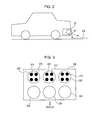
- Fig. 2 illustrates a specific installation of the camera 10. Referring to Fig. 2 , the camera 10 is installed in the middle of a rear bumper at an angle of 30 degrees downward from the horizontal. In this embodiment, a calibration sheet 200 is placed on the ground at the rear of the vehicle such that the calibration sheet is positioned within an image taking range of the camera 10.
- Fig. 3 illustrates a specific example of the calibration sheet 200.
- the calibration sheet 200 includes, as calibration marks, twelve small black circles 210 and six large white circles 220.
- the large white circles 220 are arranged such that each of two rows includes three circles when viewed from the vehicle.
- Each of the small black circles 210 and the large white circles 220 is identified on the basis of a captured image. The coordinates of the center of each circle are obtained and used for various calculations.
- the image capturing unit 12 captures an image of the surroundings at the rear of the vehicle, the image being taken through the camera 10.
- the captured image is temporarily stored into the image memory 14.
- the camera 10 takes a first image before movement of the vehicle and then takes a second image after forward movement of the vehicle by a predetermined distance.
- the first image storing unit 20 reads the image, captured before movement of the vehicle and stored in the image memory 14, and stores the read image as a first image.
- the second image storing unit 22 reads the image, captured after movement of the vehicle and stored in the image memory 14, and stores the read image as a second image.
- the first posture estimating unit 24 estimates the posture of the camera 10 on the basis of the first image stored in the first image storing unit 20 with reference to the positions of the calibration marks in the calibration sheet 200.
- Estimated values of the posture include camera position components x1, y1, and z1 and camera angle components rv1, rh1, and rr1.
- x1 denotes an X coordinate
- y1 denotes a Y coordinate
- z1 denotes a Z coordinate
- rv1 denotes a pitch angle
- rh1 denotes a yaw angle
- rr1 denotes a roll angle.
- the X-axis direction and the Y-axis direction that are orthogonal to each other are defined on a plane parallel to the ground on which the calibration sheet 200 is placed.
- the Z-axis direction is defined perpendicular to the ground.
- the second posture estimating unit 26 estimates the posture of the camera 10 on the basis of the second image stored in the second image storing unit 22 with reference to the positions of the calibration marks in the calibration sheet 200.
- Estimated values of the posture include camera position components x2, y2, and z2 and camera angle components rv2, rh2, and rr2.
- x2 and the other reference symbols denote the same meanings of x1 and the above-described other reference symbols, respectively.
- the distance calculating unit 30 calculates a distance d of actual movement of the vehicle on the basis of the estimated posture values obtained by the first posture estimating unit 24 and those obtained by the second posture estimating unit 26.
- the deviation calculating unit 32 calculates the amount of deviation of the calibration sheet 200 from a normal position (ideal design position assumed upon design) on the basis of the estimated posture values obtained by the first posture estimating unit 24 and those obtained by the second posture estimating unit 26.
- the camera posture determining unit 34 determines the posture of the camera 10 on the basis of the estimated values obtained by at least one of the first posture estimating unit 24 and the second posture estimating unit 26 and the deviation amount calculated by the deviation calculating unit 32.
- the display processing unit 42 displays an image, taken by the camera 10, on the display 40 when the vehicle is moved.
- the auxiliary line creating unit 44 creates an auxiliary line, serving as a distance target upon movement of the vehicle.
- the display processing unit 42 displays the auxiliary line such that the line is superimposed on a taken image.
- the movement completion determining unit 46 determines the completion of movement of the vehicle by the predetermined distance.
- the operation unit 50 which is configured to accept an operation instruction from a user, includes various keys.
- second image capture by the image capturing unit 12 is based on a capture instruction issued from the operation unit 50 operated by the user.
- the above-described first image storing unit 20 corresponds to first image storing means
- the second image storing unit 22 corresponds to second image storing means
- the first posture estimating unit 24 corresponds to first posture estimating means
- the second posture estimating unit 26 corresponds to second posture estimating means
- the deviation calculating unit 32 corresponds to sheet deviation calculating means
- the camera posture determining unit 34 corresponds to camera posture determining means
- the display processing unit 42 corresponds to display processing means
- the movement completion determining unit 46 corresponds to movement completion determining means.
- the in-vehicle camera posture detecting apparatus 100 has such a configuration. An operation of taking an image of the calibration sheet 200 through the camera 10 to determine the posture of the camera 10 will be described below.
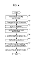
- Fig. 4 is a flowchart of a schematic procedure for determining the posture of the camera 10. While the calibration sheet 200 is placed in the predetermined position at the rear of the vehicle, the camera 10 takes a first image (step 100). Specifically, the user operates the operation unit 50 and gives an instruction for first image capture. The image capturing unit 12 captures the image taken by the camera 10 in accordance with the capture instruction and stores the image into the image memory 14. The first image storing unit 20 reads the image from the image memory 14 and stores the read image as a first image.
- the first posture estimating unit 24 reads the first image from the first image storing unit 20 and estimates the posture of the camera 10 (step 102). Thus, the camera position components x1, y1, and z1 and the camera angle components rv1, rh1, and rr1 are obtained as estimated values of the posture of the camera 10.
- the vehicle is moved by the predetermined distance (step 104). Specifically, the vehicle is moved straight forward by the predetermined distance.
- the predetermined distance an assumed ideal value (for example, 20 cm) is used. If a distance slightly differs from the ideal value but is close to this value, no problems will arise.
- the camera 10 takes a second image (step 106). Specifically, the user operates the operation unit 50 and gives an instruction for second image capture.
- the image capturing unit 12 captures the image taken by the camera 10 in accordance with the capture instruction and stores the image into the image memory 14.
- the second image storing unit 22 reads the image from the image memory 14 and stores the read image as a second image.
- the second posture estimating unit 26 reads the second image from the second image storing unit 22 and estimates the posture of the camera 10 (step 108).
- the camera position components x2, y2, and z2 and the camera angle components rv2, rh2, and rr2 are obtained as estimated values of the posture of the camera 10.
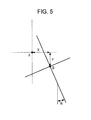
- the deviation calculating unit 32 calculates components X, Y, and R of the amount of deviation of the calibration sheet 200 from the design position (step 112).
- X denotes the deviation amount component in the X-axis direction
- Y denotes the deviation amount component in the Y-axis direction
- R denotes the deviation amount component in the direction of rotation.
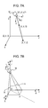
- Fig. 5 illustrates the relationship between the three deviation amount components X, Y, and R. Referring to Fig. 5 , A indicates a point in the calibration sheet 200 placed in the design position and B indicates a corresponding point in the calibration sheet 200 placed actually.
- first design position components position components (hereinafter, referred to as "first design position components") of the camera 10 derived on the assumption that the calibration sheet 200 is placed in the design position before movement of the vehicle. Since the position in the Z-axis direction is constant irrespective of deviation of the calibration sheet 200, explanation of a position component z is omitted.
- the relationship between the position components x1 and y1 of the camera 10 estimated before movement of the vehicle and the first design position components x and y is expressed as follows.
- x ⁇ 1 y ⁇ 1 cosR - sinR sinR cosR ⁇ x y + X Y
- x' and y' denote position components (hereinafter, referred to as "second design position components") of the camera 10 derived on the assumption that the calibration sheet 200 is placed in the design position after movement of the vehicle.
- second design position components position components (hereinafter, referred to as "second design position components") of the camera 10 derived on the assumption that the calibration sheet 200 is placed in the design position after movement of the vehicle.
- the relationship between the position components x2 and y2 of the camera 10 estimated after movement of the vehicle and the second design position components x' and y' is expressed as follows.
- x ⁇ 2 y ⁇ 2 cosR - sinR sinR cosR ⁇ x ⁇ y ⁇ + X Y
- the deviation calculating unit 32 can calculate the deviation amount components X, Y, and R using Expression (6).
- the camera posture determining unit 34 calculates the angle components rv (pitch angle), rh (yaw angle), and rr (roll angle) of the camera 10 which are unknown values (step 114).
- the camera posture determining unit 34 calculates the angle components rv, rh, and rr of the camera 10 in the above-described manner.
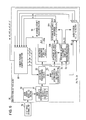
- the first posture estimating unit 24 includes a mark center detecting section 60, mark coordinate storing sections 61 and 63, a coordinate transforming section 62, an inter-mark distance adjusting section 64, a mark position adjusting section 65, and a camera posture adjusting section 66.
- the mark center detecting section 60 reads the first image stored in the first image storing unit 20 and detects the center of each calibration mark in the calibration sheet 200 included in the first image. For example, the mark center detecting section 60 extracts the twelve small black circles 210, serving as the calibration marks included in the calibration sheet 200, by image recognition and then stores the coordinates of the center of each circle into the mark coordinate storing section 61.
- the coordinates of the center are represented in the fish-eye coordinate system in which an image plane (U-V coordinate system) is defined perpendicular to the optical axis, indicated by S, of the camera 10.
- the coordinate transforming section 62 transforms the coordinates of the center of each calibration mark in the fish-eye coordinate system into those in the reference coordinate system in which the ground extends in the X-Y plane and the Z-axis direction is perpendicular to the ground, and stores the transformed coordinates into the mark coordinate storing section 63.
- Figs. 7A and 7B are diagrams explaining coordinate transformation.
- X-Y-Z represents the reference coordinate system
- U-V-S represents the fish-eye coordinate system.
- x1, y1, and z1 denote components of the distance between the origin of the fish-eye coordinate system U-V-S and that of the reference coordinate system X-Y-Z and let rx, ry, and rz denote components of the amount of rotation of the camera 10 around the respective axes of the reference coordinate system X-Y-Z, the following expression holds.
- coordinates u, v, and s of the center of the calibration mark in the fish-eye coordinate system are known values and a coefficient ⁇ is used to transform a unit in the reference coordinate system into millimeters on the basis of the actual distance between adjacent calibration marks.
- X Y Z cos rz - sin rz 0 sin rz cos rz 0 0 0 1 ⁇ cos ry 0 sin ry 0 1 0 - sin ry 0 cos ry ⁇ 1 0 0 0 cos rx - sin rx 0 sin rx cos rx ⁇ ⁇ u ⁇ ⁇ v ⁇ ⁇ s + x ⁇ 1 y ⁇ 1 z ⁇ 1
- the inter-mark distance adjusting section 64, the mark position adjusting section 65, and the camera posture adjusting section 66 determine the values rv, rh, rr, x1, y1, and z1 such that each distance between the adjacent calibration marks in each axis direction is equal to the actual distance therebetween in the axis direction and the position of each calibration mark coincides with the actual position thereof.
- the inter-mark distance adjusting section 64 and the camera posture adjusting section 66 calculate the coordinates of the center of each calibration mark using Expression (15) while changing the values rv, rh, and rr without changing the values x1, y1, and z1.
- the sections 64 and 66 calculate each distance between the adjacent calibration marks in each axis direction to obtain the values rv, rh, and rr at which the distances between the adjacent calibration marks in each axis direction are equal to one another, and output the values rv, rh, and rr as camera angle components.
- the mark position adjusting section 65 and the camera posture adjusting section 66 calculate the coordinates of the center of each calibration mark using Expression (15) to obtain the values x1, y1, and z1 at which the center coincides with the actual center (which is known) of the calibration mark, and then output the values as camera position components.
- changing the value rr enables adjustment of inclination of the calibration marks
- changing the value rh enables adjustment of the distances between the adjacent calibration marks in the vertical direction
- changing the value rv enables adjustment of the distances between the adjacent calibration marks in the horizontal direction.
- an inclination adjustment determining portion 64a calculates the angle of inclination of the calibration marks using the coordinates of the centers of the calibration marks when the values x1, y1, and z1 are constant (for example, zero).
- the inclination adjustment determining portion 64a adjusts the value rr such that the inclination angle is equal to 0 and inputs an adjustment amount ⁇ rr to the camera posture adjusting section 66.
- the coordinate transforming section 62 calculates the coordinates of the center of each calibration mark using Expression (15).
- the inclination adjustment determining portion 64a calculates the inclination angle of the calibration marks using the coordinates of the centers of the calibration marks. The above-described processes are continued to adjust the value rr until the inclination angle of the calibration marks is equal to 0.
- an inter-mark distance calculating portion 64b calculates the distances between the adjacent calibration marks in the X-axis direction.
- An inter-mark distance adjustment completion determining portion 64d determines whether the distances between the adjacent calibration marks are equal to one another. If the distances therebetween are not equal to one another, the inter-mark distance adjustment completion determining portion 64d supplies an adjustment instruction signal to an inter-mark distance adjustment determining portion 64c. Accordingly, the inter-mark distance adjustment determining portion 64c adjusts the value rh and inputs an adjustment amount ⁇ rh to the camera posture adjusting section 66.
- the coordinate transforming section 62 calculates the coordinates of the center of each calibration mark using Expression (15).
- the inter-mark distance calculating portion 64b calculates the distances between the adjacent calibration marks in the X-axis direction on the basis of the coordinates of the centers of the calibration marks. The value rh is adjusted until the distances between the adjacent calibration marks in the X-axis direction are equal to one another.
- the inter-mark distance calculating portion 64b calculates the distances between the adjacent calibration marks in the Y-axis direction.
- the inter-mark distance adjustment completion determining portion 64d determines whether the distances between the adjacent calibration marks in the Y-axis direction are equal to one another. If the distances therebetween are not equal to one another, the inter-mark distance adjustment completion determining portion 64d supplies an adjustment instruction signal to the inter-mark distance adjustment determining portion 64c. Accordingly, the inter-mark distance adjustment determining portion 64c adjusts the value rv and inputs an adjustment amount ⁇ rv to the camera posture adjusting section 66.
- the coordinate transforming section 62 calculates the coordinates of the center of each calibration mark using Expression (15).
- the inter-mark distance calculating portion 64b calculates the distances between the adjacent calibration marks in the Y-axis direction on the basis of the coordinates of the centers of the calibration marks. The value rv is adjusted until the distances between the adjacent calibration marks in the Y-axis direction are equal to one another.
- the inter-mark distance adjustment completion determining portion 64d outputs an installation angle adjustment completion signal DAJED.
- the mark position adjusting section 65 obtains the values x1 and y1 at which the center of each calibration mark coincides with the actual center (Xs, Ys) using Expression (15) in response to the installation angle adjustment completion signal DAJED. In addition, the mark position adjusting section 65 adjusts the value z1 such that the size of each calibration mark (or each distance between the adjacent calibration marks) coincides with the actual one, and outputs the values x1, y1, and z1 as camera position components. After that, the camera posture adjusting section 66 outputs the calculated camera angle components rv1, rh1, and rr1 and camera position components x1, y1, and z1 from the first posture estimating unit 24.
- the in-vehicle camera posture detecting apparatus 100 calculates the deviation amount of the calibration sheet 200 from the predetermined position (design position) on the basis of the images captured before and after movement of the vehicle.
- the effect of the deviation of the calibration sheet 200 can therefore be eliminated.
- the posture of the camera 10 can be accurately detected.
- the predetermined distance d by which the vehicle is moved is determined on the basis of the estimated values obtained by the first and second posture estimating units 24 and 26, the distance d can be accurately grasped.
- an error of estimation of the camera posture based on the second image captured after movement can be reduced.
- step 104 of Fig. 4 the vehicle is moved by the predetermined distance.
- the ideal value design value
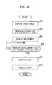
- Fig. 8 is a flowchart of a procedure for providing a notification when the vehicle is moved by the predetermined distance according to a modification of the embodiment.
- the display processing unit 42 displays an image (check image) taken through the camera 10 on a screen of the display 40 (step 200) prior to movement of the vehicle (step 104 of Fig. 4 ).
- the auxiliary line creating unit 44 creates an auxiliary line to be superimposed on the image displayed in step 200 (step 202). This auxiliary line is displayed so as to be superimposed on the check image by the display processing unit 42.
- Figs. 9A and 9B illustrate specific examples of check images displayed before and after movement of the vehicle.
- Fig. 9A illustrates the image before movement
- Fig. 9B illustrates the image after movement.
- markers M are arranged at corners of the calibration sheet 200 adjacent to the vehicle.
- the markers M may be actually included in the calibration sheet 200 such that each marker has a specific color or shape.
- the auxiliary line creating unit 44 may recognize the corners of the calibration sheet 200 and create the markers M as images to be superimposed.
- the auxiliary line creating unit 44 creates an auxiliary line H which is positioned at a distance above the markers M. This arrangement means that the auxiliary line H is located in an area at the rear of the markers M.
- the predetermined distance has to correspond to a length that is equal to a vehicle movement distance extending along the ground. After the positions of the markers M are determined, the position spaced apart from the markers M by the predetermined distance can be calculated. This position may be calculated on the basis of estimation (camera angle components) by the first posture estimating unit 24.
- the vehicle is moved (step 204). As the vehicle is moved, the position of the calibration sheet 200 included in the displayed image is moved upward (backward) but the position of the auxiliary line H illustrated in Fig. 9A is fixed in the screen.
- the movement completion determining unit 46 determines whether the markers M in the calibration sheet 200, moved upward (backward) in the screen, coincide with or have passed the auxiliary line H (step 206). If the markers M do not coincide with or have not yet passed the auxiliary line H, the movement completion determining unit 46 determines "NO" and the determination in this step is repeated.
- the movement completion determining unit 46 determines "YES" in step 206.
- Fig. 9B illustrates a state in which the markers M coincide with the auxiliary line H.
- the movement completion determining unit 46 then provides a notification indicating that the vehicle movement is completed (step 208).
- the movement completion determining unit 46 permits the display processing unit 42 to display a message indicating the completion of movement on the display 40.
- a voice message or alarm indicating the completion of movement may be output from a speaker or buzzer.
- the driver stops moving the vehicle (step 210).
- the driver can recognize the physical relationship between the markers M and the auxiliary line H while viewing the check images displayed on the display 40.
- the driver can readily determine a distance by which the vehicle is to be moved. Since the markers and the auxiliary line may be included in the check image or a notification may be provided on completion of the movement by the predetermined distance, the driver can be reliably informed of the completion of movement of the vehicle by the predetermined distance.
- this prevents a distance of movement of the vehicle from becoming longer than necessary.
- the present invention is not limited to the above-described embodiment and various changes and modifications can be made without departing from the spirit and scope of the invention.
- the first image storing unit 20 and the second image storing unit 22 are separated and the first posture estimating unit 24 and the second posture estimating unit 26 are separated.
- the first and second units 20 and 22 fundamentally perform the same process and the first and second units 24 and 26 also fundamentally perform the same process. Accordingly, one of the first and second units may be omitted and the other unit may repeat the same process.
- the above-described embodiment has been described with respect to the camera 10 that takes an image of surroundings at the rear of a vehicle.
- the present invention is applicable to determination of the posture of a camera that takes an image of surroundings in front of or at a side of a vehicle.
- the amount of deviation of the calibration sheet 200 from the predetermined position (design position) is calculated on the basis of images before and after movement of the vehicle as described above, the effect of the deviation of the calibration sheet 200 can be eliminated.
- the posture of the camera 10 can be accurately detected.
Landscapes
- Engineering & Computer Science (AREA)
- Computer Vision & Pattern Recognition (AREA)
- Physics & Mathematics (AREA)
- General Physics & Mathematics (AREA)
- Theoretical Computer Science (AREA)
- Length Measuring Devices By Optical Means (AREA)
- Closed-Circuit Television Systems (AREA)
Abstract
Description
- The present invention relates to an in-vehicle camera posture detecting apparatus and method for detecting an installation angle and the like of a camera that is mounted on a vehicle and captures an image of surroundings of the vehicle.
- In order to accurately detect the position or size of a subject included in an image captured by a camera mounted on a vehicle on the basis of the image, or in order to combine images of adjacent regions captured by cameras such that the resultant image is seamless, the installation position and angle of the camera or each camera have to be accurately determined.
- The installation position and angle of a typical camera are often predetermined upon design of a system including the camera. Since an installation error is actually caused, calibration is performed after installation and the installation position and angle are then detected. For example, a camera installation angle calculating method has been known by which the installation position and angle of a camera are detected on the basis of images of a calibration sheet captured through the camera, the calibration sheet being placed in a predetermined position near a vehicle and having a printed calibration pattern including a plurality of calibration marks (cf.
JP 2010-183265 A Figs. 1 to 23 , for example). - The above-described method assumes that the calibration sheet is accurately placed in the predetermined position. Disadvantageously, if the placed calibration sheet is deviated from the predetermined position, the posture (position and angle) of the camera will fail to be accurately detected. For example, it is assumed that the calibration sheet is placed on the ground at the rear of the vehicle such that the placed calibration sheet is aligned with one end of a rear bumper and an image of the calibration sheet is captured by the camera installed in the rear of the vehicle. Although the position of the calibration sheet is positioned in that manner, it is difficult to align the calibration sheet with the end of the rear bumper, since the rear bumper is spaced apart from the ground. The same applies to the positions of the right and left sides of the calibration sheet. It is also difficult to accurately align the middle of the vehicle along the width thereof with the middle of the calibration sheet in the direction along the width of the vehicle.
- In consideration of the above-described circumstances, it may be an object of the present invention to provide an in-vehicle camera posture detecting apparatus and method capable of accurately detecting the posture of a camera.
- The object is solved by the features of the independent claims. Further embodiments and developments are defined in the respective dependent claims.
- According to an aspect of the present invention, an in-vehicle camera posture detecting apparatus for detecting the posture of a camera mounted on a vehicle on the basis of images of a plurality of calibration marks included in a calibration sheet placed near the vehicle, the images being captured through the camera, includes the following elements. A first image storing unit stores, as a first image, an image of the calibration sheet captured through the camera. A first posture estimating unit estimates the posture of the camera on the basis of the first image stored in the first image storing unit. A second image storing unit stores, as a second image, an image of the calibration sheet captured through the camera after movement of the vehicle by a predetermined distance. A second posture estimating unit estimates the posture of the camera on the basis of the second image stored in the second image storing unit. A sheet deviation calculating unit calculates the amount of deviation of the calibration sheet from a predetermined position on the basis of estimations by the first and second posture estimating units. A camera posture determining unit determines the posture of the camera on the basis of a estimated posture value obtained by at least one of the first and second posture estimating units and the deviation amount calculated by the sheet deviation calculating unit.
- According to another aspect of the present invention, a method for detecting the posture of a camera mounted on a vehicle on the basis of images of a plurality of calibration marks included in a calibration sheet placed near the vehicle, the images being captured through the camera, includes estimating, by a first posture estimating unit, the posture of the camera on the basis of an image of the calibration sheet captured through the camera, estimating, by a second posture estimating unit, the posture of the camera on the basis of an image of the calibration sheet captured through the camera after movement of the vehicle by a predetermined distance, calculating, by a sheet deviation calculating unit, the amount of deviation of the calibration sheet from a predetermined position on the basis of estimations by the first and second posture estimating units, and determining, by a camera posture determining unit, the posture of the camera on the basis of a estimated posture value obtained by at least one of the first and second posture estimating units and the deviation amount calculated by the sheet deviation calculating unit.
- Since the amount of deviation of the calibration sheet from the predetermined position (design position) is calculated on the basis of the images captured before and after movement of the vehicle, the effect of the deviation of the calibration sheet can be eliminated. Thus, the posture of the camera can be accurately detected.
- Preferably, the apparatus further comprises a distance calculating unit configured to calculate the predetermined distance by which the vehicle is moved on the basis of estimated posture values obtained by the first and second posture estimating units. Consequently, the distance of movement of the vehicle can be accurately grasped, thus reducing an error in the estimated posture of the camera based on the second image.
- Preferably, the sheet deviation calculating unit assumes that the camera is installed in a design position and calculates the deviation amount on the basis of the relationship between the design position of the camera, the estimations by the first and second posture estimating units, and the deviation amount of the calibration sheet from the predetermined position. Since the design position of the camera and estimated posture values are known values in this relationship, the deviation amount which is remaining can be calculated.
- Preferably, the camera posture determining unit determines an actual camera angle on the basis of the relationship between camera angles estimated by the first and second posture estimating units, the actual camera angle, and a component in the direction of rotation of the deviation amount of the calibration sheet calculated by the sheet deviation calculating unit. Since the estimated camera angles and the component in the direction of rotation of the deviation amount of the calibration sheet are known values, the actual camera angle which is remaining can be calculated.
- Preferably, the camera posture determining unit determines the posture of the camera on the basis of a estimated posture value obtained by the first posture estimating unit. An error caused upon determination of the posture of the camera can be reduced, since an estimated value obtained using the calibration sheet placed near the vehicle is used.
- Preferably, the vehicle is moved straight. In the case where images of the calibration sheet are captured before and after movement, the amount of deviation in the direction of rotation of the calibration sheet can be kept constant. The number of parameters to be calculated can therefore be reduced. Thus, processing can be simplified.
- The apparatus may further include a display processing unit that displays a check image on a display, the check image being used to determine whether the vehicle has been moved by the predetermined distance. Accordingly, a driver of the vehicle can move the vehicle while viewing the check image. It is therefore easy to move the vehicle by the predetermined distance.
- Preferably, the check image includes a marker that moves in the check image as the vehicle is moved and an auxiliary line whose display position is fixed in the check image. The check image may be displayed such that the marker coincides with the auxiliary line at the timing when the movement of the vehicle by the predetermined distance is completed. Alternatively, the apparatus may further include a movement completion determining unit that determines on the basis of images captured through the camera whether the movement of the vehicle by the predetermined distance is completed and provides a predetermined notification on completion of the movement. Accordingly, the driver can be reliably notified of the movement of the vehicle by the predetermined distance. Thus, the distance of movement of the vehicle can be prevented from becoming longer than necessary.
-
-
Fig. 1 is a block diagram of the configuration of an in-vehicle camera posture detecting apparatus according to an embodiment of the present invention; -
Fig. 2 is a diagram illustrating a specific installation of a camera; -
Fig. 3 is a diagram illustrating a specific example of a calibration sheet; -
Fig. 4 is a flowchart of a schematic procedure for determining the posture of the camera; -
Fig. 5 is a diagram illustrating the relationship between three components of the amount of deviation; -
Fig. 6 is a block diagram of the detailed configuration of a first posture estimating unit; -
Figs. 7A and 7B are diagrams explaining coordinate transformation; -
Fig. 8 is a flowchart of a procedure for providing a notification on completion of movement of the vehicle by a predetermined distance according to a modification of the embodiment; and -
Figs. 9A and 9B are diagrams illustrating specific examples of check images displayed before and after movement of the vehicle. - An in-vehicle camera posture detecting apparatus according to an embodiment of the present invention will be described below with reference to the drawings.
-
Fig. 1 illustrates the configuration of the in-vehicle camera posture detecting apparatus according to the embodiment. Referring toFig. 1 , the in-vehicle camera posture detecting apparatus, indicated at 100, according to the embodiment includes acamera 10, animage capturing unit 12, animage memory 14, a firstimage storing unit 20, a secondimage storing unit 22, a firstposture estimating unit 24, a secondposture estimating unit 26, adistance calculating unit 30, adeviation calculating unit 32, a cameraposture determining unit 34, adisplay 40, adisplay processing unit 42, an auxiliaryline creating unit 44, a movementcompletion determining unit 46, and anoperation unit 50. The camera, whose posture is detected by the in-vehicle cameraposture detecting apparatus 100, is to be used in another apparatus such that the other apparatus uses a result of detection by the camera. The components of the in-vehicle cameraposture detecting apparatus 100 may be included in the other apparatus. - The
camera 10, which is installed at a predetermined angle in a predetermined position in the rear of a vehicle, takes an image of surroundings at the rear of the vehicle through, for example, a fish-eye lens or a wide-angle lens.Fig. 2 illustrates a specific installation of thecamera 10. Referring toFig. 2 , thecamera 10 is installed in the middle of a rear bumper at an angle of 30 degrees downward from the horizontal. In this embodiment, acalibration sheet 200 is placed on the ground at the rear of the vehicle such that the calibration sheet is positioned within an image taking range of thecamera 10. -
Fig. 3 illustrates a specific example of thecalibration sheet 200. Referring toFig. 3 , thecalibration sheet 200 includes, as calibration marks, twelve smallblack circles 210 and six largewhite circles 220. The largewhite circles 220 are arranged such that each of two rows includes three circles when viewed from the vehicle. The three largewhite circles 220, included in the row farther from the vehicle, each include four smallblack circles 210 arranged in an array of two columns by two rows. Each of the smallblack circles 210 and the largewhite circles 220 is identified on the basis of a captured image. The coordinates of the center of each circle are obtained and used for various calculations. - The
image capturing unit 12 captures an image of the surroundings at the rear of the vehicle, the image being taken through thecamera 10. The captured image is temporarily stored into theimage memory 14. In this embodiment, while thecalibration sheet 200 is placed in a predetermined position at the rear of the vehicle, thecamera 10 takes a first image before movement of the vehicle and then takes a second image after forward movement of the vehicle by a predetermined distance. - The first
image storing unit 20 reads the image, captured before movement of the vehicle and stored in theimage memory 14, and stores the read image as a first image. The secondimage storing unit 22 reads the image, captured after movement of the vehicle and stored in theimage memory 14, and stores the read image as a second image. - The first
posture estimating unit 24 estimates the posture of thecamera 10 on the basis of the first image stored in the firstimage storing unit 20 with reference to the positions of the calibration marks in thecalibration sheet 200. Estimated values of the posture include camera position components x1, y1, and z1 and camera angle components rv1, rh1, and rr1. In this case, x1 denotes an X coordinate, y1 denotes a Y coordinate, z1 denotes a Z coordinate, rv1 denotes a pitch angle, rh1 denotes a yaw angle, and rr1 denotes a roll angle. The X-axis direction and the Y-axis direction that are orthogonal to each other are defined on a plane parallel to the ground on which thecalibration sheet 200 is placed. The Z-axis direction is defined perpendicular to the ground. - The second
posture estimating unit 26 estimates the posture of thecamera 10 on the basis of the second image stored in the secondimage storing unit 22 with reference to the positions of the calibration marks in thecalibration sheet 200. Estimated values of the posture include camera position components x2, y2, and z2 and camera angle components rv2, rh2, and rr2. In this case, x2 and the other reference symbols denote the same meanings of x1 and the above-described other reference symbols, respectively. - The
distance calculating unit 30 calculates a distance d of actual movement of the vehicle on the basis of the estimated posture values obtained by the firstposture estimating unit 24 and those obtained by the secondposture estimating unit 26. - The
deviation calculating unit 32 calculates the amount of deviation of thecalibration sheet 200 from a normal position (ideal design position assumed upon design) on the basis of the estimated posture values obtained by the firstposture estimating unit 24 and those obtained by the secondposture estimating unit 26. - The camera
posture determining unit 34 determines the posture of thecamera 10 on the basis of the estimated values obtained by at least one of the firstposture estimating unit 24 and the secondposture estimating unit 26 and the deviation amount calculated by thedeviation calculating unit 32. - The
display processing unit 42 displays an image, taken by thecamera 10, on thedisplay 40 when the vehicle is moved. The auxiliaryline creating unit 44 creates an auxiliary line, serving as a distance target upon movement of the vehicle. Thedisplay processing unit 42 displays the auxiliary line such that the line is superimposed on a taken image. The movementcompletion determining unit 46 determines the completion of movement of the vehicle by the predetermined distance. - The
operation unit 50, which is configured to accept an operation instruction from a user, includes various keys. For example, second image capture by theimage capturing unit 12 is based on a capture instruction issued from theoperation unit 50 operated by the user. - The above-described first
image storing unit 20 corresponds to first image storing means, the secondimage storing unit 22 corresponds to second image storing means, the firstposture estimating unit 24 corresponds to first posture estimating means, the secondposture estimating unit 26 corresponds to second posture estimating means, thedeviation calculating unit 32 corresponds to sheet deviation calculating means, the cameraposture determining unit 34 corresponds to camera posture determining means, thedisplay processing unit 42 corresponds to display processing means, and the movementcompletion determining unit 46 corresponds to movement completion determining means. - The in-vehicle camera
posture detecting apparatus 100 according to the embodiment has such a configuration. An operation of taking an image of thecalibration sheet 200 through thecamera 10 to determine the posture of thecamera 10 will be described below. -
Fig. 4 is a flowchart of a schematic procedure for determining the posture of thecamera 10. While thecalibration sheet 200 is placed in the predetermined position at the rear of the vehicle, thecamera 10 takes a first image (step 100). Specifically, the user operates theoperation unit 50 and gives an instruction for first image capture. Theimage capturing unit 12 captures the image taken by thecamera 10 in accordance with the capture instruction and stores the image into theimage memory 14. The firstimage storing unit 20 reads the image from theimage memory 14 and stores the read image as a first image. - The first
posture estimating unit 24 reads the first image from the firstimage storing unit 20 and estimates the posture of the camera 10 (step 102). Thus, the camera position components x1, y1, and z1 and the camera angle components rv1, rh1, and rr1 are obtained as estimated values of the posture of thecamera 10. - The vehicle is moved by the predetermined distance (step 104). Specifically, the vehicle is moved straight forward by the predetermined distance. As for the predetermined distance, an assumed ideal value (for example, 20 cm) is used. If a distance slightly differs from the ideal value but is close to this value, no problems will arise.
- Then, the
camera 10 takes a second image (step 106). Specifically, the user operates theoperation unit 50 and gives an instruction for second image capture. Theimage capturing unit 12 captures the image taken by thecamera 10 in accordance with the capture instruction and stores the image into theimage memory 14. The secondimage storing unit 22 reads the image from theimage memory 14 and stores the read image as a second image. - The second
posture estimating unit 26 reads the second image from the secondimage storing unit 22 and estimates the posture of the camera 10 (step 108). Thus, the camera position components x2, y2, and z2 and the camera angle components rv2, rh2, and rr2 are obtained as estimated values of the posture of thecamera 10. - The
distance calculating unit 30 calculates the distance d of movement of the vehicle on the basis of the two camera positions obtained by estimations in the above-describedsteps 102 and 108 (step 110). Specifically, thedistance calculating unit 30 calculates the distance d using the camera position components x1 and y1 in the first estimation and the camera position components x2 and y2 in the second estimation by the following expression.
- The
deviation calculating unit 32 calculates components X, Y, and R of the amount of deviation of thecalibration sheet 200 from the design position (step 112). In this case, X denotes the deviation amount component in the X-axis direction, Y denotes the deviation amount component in the Y-axis direction, and R denotes the deviation amount component in the direction of rotation.Fig. 5 illustrates the relationship between the three deviation amount components X, Y, and R. Referring toFig. 5 , A indicates a point in thecalibration sheet 200 placed in the design position and B indicates a corresponding point in thecalibration sheet 200 placed actually. - Let x and y denote position components (hereinafter, referred to as "first design position components") of the
camera 10 derived on the assumption that thecalibration sheet 200 is placed in the design position before movement of the vehicle. Since the position in the Z-axis direction is constant irrespective of deviation of thecalibration sheet 200, explanation of a position component z is omitted. The relationship between the position components x1 and y1 of thecamera 10 estimated before movement of the vehicle and the first design position components x and y is expressed as follows.
- Similarly, let x' and y' denote position components (hereinafter, referred to as "second design position components") of the
camera 10 derived on the assumption that thecalibration sheet 200 is placed in the design position after movement of the vehicle. The relationship between the position components x2 and y2 of thecamera 10 estimated after movement of the vehicle and the second design position components x' and y' is expressed as follows.
- When Expressions (2) and (3) are expanded, the following expression is obtained.

- Expression (4) is expressed as a determinant in terms of the deviation amount (X, Y, R) of the
calibration sheet 200 as follows.
- Expression (5) is transformed as follows.

- Assuming that the vehicle is moved in the Y-axis direction, the relationship between the first design position components x and y of the
camera 10 and the second design position components x' and y' is expressed as follows.
- All of the values in the right sides of Expression (6) are known. The
deviation calculating unit 32 can calculate the deviation amount components X, Y, and R using Expression (6). - The camera
posture determining unit 34 calculates the angle components rv (pitch angle), rh (yaw angle), and rr (roll angle) of thecamera 10 which are unknown values (step 114). The relationship among the actual angle components rv, rh, and rr of thecamera 10, the estimated values rv1, rh1, and rr1, and the deviation amount component R of thecalibration sheet 200 can be expressed as follows:
where Rx(rv), Ry(rh), and Rz(rr) are the following rotation matrices.


- Expression (8) is transformed as follows.

- Since all of the values in the right side of Expression (12) are known, the expression is expanded as follows.

- Furthermore, the left side of Expression (12) is expanded and is then solved together with Expression (13) as follows.

- The camera
posture determining unit 34 calculates the angle components rv, rh, and rr of thecamera 10 in the above-described manner. - Camera posture estimating operations of the first and second
posture estimating units posture estimating units posture estimating unit 24 will be described in detail below. -
Fig. 6 illustrates the detailed configuration of the firstposture estimating unit 24. Referring toFig. 6 , the firstposture estimating unit 24 includes a markcenter detecting section 60, mark coordinate storingsections section 62, an inter-markdistance adjusting section 64, a markposition adjusting section 65, and a cameraposture adjusting section 66. - The mark
center detecting section 60 reads the first image stored in the firstimage storing unit 20 and detects the center of each calibration mark in thecalibration sheet 200 included in the first image. For example, the markcenter detecting section 60 extracts the twelve smallblack circles 210, serving as the calibration marks included in thecalibration sheet 200, by image recognition and then stores the coordinates of the center of each circle into the mark coordinate storingsection 61. The coordinates of the center are represented in the fish-eye coordinate system in which an image plane (U-V coordinate system) is defined perpendicular to the optical axis, indicated by S, of thecamera 10. - The coordinate transforming
section 62 transforms the coordinates of the center of each calibration mark in the fish-eye coordinate system into those in the reference coordinate system in which the ground extends in the X-Y plane and the Z-axis direction is perpendicular to the ground, and stores the transformed coordinates into the mark coordinate storingsection 63. -
Figs. 7A and 7B are diagrams explaining coordinate transformation. Referring toFigs. 7A and 7B , X-Y-Z represents the reference coordinate system and U-V-S represents the fish-eye coordinate system. InFigs. 7A and 7B , when x1, y1, and z1 denote components of the distance between the origin of the fish-eye coordinate system U-V-S and that of the reference coordinate system X-Y-Z and let rx, ry, and rz denote components of the amount of rotation of thecamera 10 around the respective axes of the reference coordinate system X-Y-Z, the following expression holds. Note that coordinates u, v, and s of the center of the calibration mark in the fish-eye coordinate system are known values and a coefficient λ is used to transform a unit in the reference coordinate system into millimeters on the basis of the actual distance between adjacent calibration marks.
- Referring to
Fig. 7B , when the optical axis of thecamera 10 points a point P on the X-Y plane, the amount of rotation around the X axis is rv (= rx), that around the Y axis is rh (= ry), and that around the Z axis is rr (= rz). These rotation amounts correspond to a pitch angle, a yaw angle, and a roll angle, respectively. - After that, the inter-mark
distance adjusting section 64, the markposition adjusting section 65, and the cameraposture adjusting section 66 determine the values rv, rh, rr, x1, y1, and z1 such that each distance between the adjacent calibration marks in each axis direction is equal to the actual distance therebetween in the axis direction and the position of each calibration mark coincides with the actual position thereof. Specifically, the inter-markdistance adjusting section 64 and the cameraposture adjusting section 66 calculate the coordinates of the center of each calibration mark using Expression (15) while changing the values rv, rh, and rr without changing the values x1, y1, and z1. Then, thesections position adjusting section 65 and the cameraposture adjusting section 66 calculate the coordinates of the center of each calibration mark using Expression (15) to obtain the values x1, y1, and z1 at which the center coincides with the actual center (which is known) of the calibration mark, and then output the values as camera position components. - Specifically, changing the value rr enables adjustment of inclination of the calibration marks, changing the value rh enables adjustment of the distances between the adjacent calibration marks in the vertical direction, and changing the value rv enables adjustment of the distances between the adjacent calibration marks in the horizontal direction.
- First, therefore, an inclination
adjustment determining portion 64a calculates the angle of inclination of the calibration marks using the coordinates of the centers of the calibration marks when the values x1, y1, and z1 are constant (for example, zero). In the case where the arrangement of the calibration marks is inclined, the inclinationadjustment determining portion 64a adjusts the value rr such that the inclination angle is equal to 0 and inputs an adjustment amount Δrr to the cameraposture adjusting section 66. The cameraposture adjusting section 66 calculates a new value rr on the basis of rr=rr+Δrr and inputs the calculated value to the coordinate transformingsection 62. The coordinate transformingsection 62 calculates the coordinates of the center of each calibration mark using Expression (15). The inclinationadjustment determining portion 64a calculates the inclination angle of the calibration marks using the coordinates of the centers of the calibration marks. The above-described processes are continued to adjust the value rr until the inclination angle of the calibration marks is equal to 0. - On completion of the adjustment of the value rr such that the inclination angle of the calibration marks is equal to 0, an inter-mark
distance calculating portion 64b calculates the distances between the adjacent calibration marks in the X-axis direction. An inter-mark distance adjustmentcompletion determining portion 64d determines whether the distances between the adjacent calibration marks are equal to one another. If the distances therebetween are not equal to one another, the inter-mark distance adjustmentcompletion determining portion 64d supplies an adjustment instruction signal to an inter-mark distanceadjustment determining portion 64c. Accordingly, the inter-mark distanceadjustment determining portion 64c adjusts the value rh and inputs an adjustment amount Δrh to the cameraposture adjusting section 66. The cameraposture adjusting section 66 calculates a new value rh on the basis of rh=rh+Δrh and inputs the calculated value to the coordinate transformingsection 62. The coordinate transformingsection 62 calculates the coordinates of the center of each calibration mark using Expression (15). The inter-markdistance calculating portion 64b calculates the distances between the adjacent calibration marks in the X-axis direction on the basis of the coordinates of the centers of the calibration marks. The value rh is adjusted until the distances between the adjacent calibration marks in the X-axis direction are equal to one another. - On completion of the adjustment of the value rh, the inter-mark
distance calculating portion 64b calculates the distances between the adjacent calibration marks in the Y-axis direction. The inter-mark distance adjustmentcompletion determining portion 64d determines whether the distances between the adjacent calibration marks in the Y-axis direction are equal to one another. If the distances therebetween are not equal to one another, the inter-mark distance adjustmentcompletion determining portion 64d supplies an adjustment instruction signal to the inter-mark distanceadjustment determining portion 64c. Accordingly, the inter-mark distanceadjustment determining portion 64c adjusts the value rv and inputs an adjustment amount Δrv to the cameraposture adjusting section 66. The cameraposture adjusting section 66 calculates a new value rv on the basis of rv=rv+Δrv and inputs the calculated value to the coordinate transformingsection 62. The coordinate transformingsection 62 calculates the coordinates of the center of each calibration mark using Expression (15). The inter-markdistance calculating portion 64b calculates the distances between the adjacent calibration marks in the Y-axis direction on the basis of the coordinates of the centers of the calibration marks. The value rv is adjusted until the distances between the adjacent calibration marks in the Y-axis direction are equal to one another. - On completion of the adjustment of the values rv (= rvl), rh (= rh1), and rr (= rr1) in the above-described manner, the inter-mark distance adjustment
completion determining portion 64d outputs an installation angle adjustment completion signal DAJED. - The mark
position adjusting section 65 obtains the values x1 and y1 at which the center of each calibration mark coincides with the actual center (Xs, Ys) using Expression (15) in response to the installation angle adjustment completion signal DAJED. In addition, the markposition adjusting section 65 adjusts the value z1 such that the size of each calibration mark (or each distance between the adjacent calibration marks) coincides with the actual one, and outputs the values x1, y1, and z1 as camera position components. After that, the cameraposture adjusting section 66 outputs the calculated camera angle components rv1, rh1, and rr1 and camera position components x1, y1, and z1 from the firstposture estimating unit 24. - As described above, the in-vehicle camera
posture detecting apparatus 100 according to the embodiment calculates the deviation amount of thecalibration sheet 200 from the predetermined position (design position) on the basis of the images captured before and after movement of the vehicle. The effect of the deviation of thecalibration sheet 200 can therefore be eliminated. The posture of thecamera 10 can be accurately detected. - Furthermore, since the predetermined distance d by which the vehicle is moved is determined on the basis of the estimated values obtained by the first and second
posture estimating units - In
step 104 ofFig. 4 , the vehicle is moved by the predetermined distance. In order to approach the distance of movement to the ideal value (design value), it is preferable to inform a driver of the completion of movement of the vehicle by the predetermined distance in some way. -
Fig. 8 is a flowchart of a procedure for providing a notification when the vehicle is moved by the predetermined distance according to a modification of the embodiment. Thedisplay processing unit 42 displays an image (check image) taken through thecamera 10 on a screen of the display 40 (step 200) prior to movement of the vehicle (step 104 ofFig. 4 ). In addition, the auxiliaryline creating unit 44 creates an auxiliary line to be superimposed on the image displayed in step 200 (step 202). This auxiliary line is displayed so as to be superimposed on the check image by thedisplay processing unit 42. -
Figs. 9A and 9B illustrate specific examples of check images displayed before and after movement of the vehicle.Fig. 9A illustrates the image before movement andFig. 9B illustrates the image after movement. InFigs. 9A and 9B , markers M are arranged at corners of thecalibration sheet 200 adjacent to the vehicle. The markers M may be actually included in thecalibration sheet 200 such that each marker has a specific color or shape. Alternatively, the auxiliaryline creating unit 44 may recognize the corners of thecalibration sheet 200 and create the markers M as images to be superimposed. In addition, the auxiliaryline creating unit 44 creates an auxiliary line H which is positioned at a distance above the markers M. This arrangement means that the auxiliary line H is located in an area at the rear of the markers M. The predetermined distance has to correspond to a length that is equal to a vehicle movement distance extending along the ground. After the positions of the markers M are determined, the position spaced apart from the markers M by the predetermined distance can be calculated. This position may be calculated on the basis of estimation (camera angle components) by the firstposture estimating unit 24. - After such an image is displayed, the vehicle is moved (step 204). As the vehicle is moved, the position of the
calibration sheet 200 included in the displayed image is moved upward (backward) but the position of the auxiliary line H illustrated inFig. 9A is fixed in the screen. - Simultaneously with the movement of the vehicle, the movement
completion determining unit 46 determines whether the markers M in thecalibration sheet 200, moved upward (backward) in the screen, coincide with or have passed the auxiliary line H (step 206). If the markers M do not coincide with or have not yet passed the auxiliary line H, the movementcompletion determining unit 46 determines "NO" and the determination in this step is repeated. - If the markers M coincide with or have passed the auxiliary line H, namely, the vehicle has been moved by the predetermined distance, the movement
completion determining unit 46 determines "YES" instep 206.Fig. 9B illustrates a state in which the markers M coincide with the auxiliary line H. The movementcompletion determining unit 46 then provides a notification indicating that the vehicle movement is completed (step 208). For example, the movementcompletion determining unit 46 permits thedisplay processing unit 42 to display a message indicating the completion of movement on thedisplay 40. Alternatively, a voice message or alarm indicating the completion of movement may be output from a speaker or buzzer. When receiving the notification, the driver stops moving the vehicle (step 210). - As described above, according to the in-vehicle camera
posture detecting apparatus 100 of the present embodiment, the driver can recognize the physical relationship between the markers M and the auxiliary line H while viewing the check images displayed on thedisplay 40. Advantageously, the driver can readily determine a distance by which the vehicle is to be moved. Since the markers and the auxiliary line may be included in the check image or a notification may be provided on completion of the movement by the predetermined distance, the driver can be reliably informed of the completion of movement of the vehicle by the predetermined distance. Advantageously, this prevents a distance of movement of the vehicle from becoming longer than necessary. - It is to be understood that the present invention is not limited to the above-described embodiment and various changes and modifications can be made without departing from the spirit and scope of the invention. For example, in the above-described embodiment, the first
image storing unit 20 and the secondimage storing unit 22 are separated and the firstposture estimating unit 24 and the secondposture estimating unit 26 are separated. The first andsecond units second units - Furthermore, the above-described embodiment has been described with respect to the
camera 10 that takes an image of surroundings at the rear of a vehicle. The present invention is applicable to determination of the posture of a camera that takes an image of surroundings in front of or at a side of a vehicle. - According to the present invention, since the amount of deviation of the
calibration sheet 200 from the predetermined position (design position) is calculated on the basis of images before and after movement of the vehicle as described above, the effect of the deviation of thecalibration sheet 200 can be eliminated. Thus, the posture of thecamera 10 can be accurately detected.
Claims (10)
- An in-vehicle camera posture detecting apparatus (100) for detecting the posture of a camera (10) mounted on a vehicle on the basis of images of a plurality of calibration marks included in a calibration sheet (200) to be placed near the vehicle, the images being captured through the camera, the apparatus comprising:a first image storing unit (20) configured to store, as a first image, an image of the calibration sheet (200) captured through the camera (10);a first posture estimating unit (24) configured to estimate the posture of the camera (10) on the basis of the first image stored in the first image storing unit (20);a second image storing unit (22) configured to store, as a second image, an image of the calibration sheet (200) captured through the camera (10) after movement of the vehicle by a predetermined distance;a second posture estimating unit (26) configured to estimate the posture of the camera (10) on the basis of the second image stored in the second image storing unit (22);a sheet deviation calculating unit (32) configured to calculate the amount of deviation of the calibration sheet (200) from a predetermined position on the basis of estimations by the first (24) and second (26) posture estimating units; anda camera posture determining unit (34) configured to determine the posture of the camera (10) on the basis of a estimated posture value obtained by at least one of the first (24) and second (26) posture estimating units and the deviation amount calculated by the sheet deviation calculating unit (32).
- The apparatus according to Claim 1, wherein the apparatus further comprises a distance calculating unit (30) configured to calculate the predetermined distance by which the vehicle is moved on the basis of estimated posture values obtained by the first (24) and second (26) posture estimating units.
- The apparatus according to Claim 1 or 2, wherein the sheet deviation calculating unit (32) is configured with the assumption that the camera (10) is installed in a design position and to calculate the deviation amount on the basis of the relationship between the design position of the camera (10), the estimations by the first (24) and second (26) posture estimating units, and the deviation amount of the calibration sheet (200) from the predetermined position.
- The apparatus according to any one of Claims 1 to 3, wherein the camera posture determining unit (34) is configured to determine an actual camera angle on the basis of the relationship between camera angles estimated by the first (24) and second (26) posture estimating units, the actual camera angle, and a component in the direction of rotation of the deviation amount of the calibration sheet (200) calculated by the sheet deviation calculating unit (32).
- The apparatus according to any one of Claims 1 to 4, wherein the camera posture determining unit (34) is configured to determine the posture of the camera (10) on the basis of a estimated posture value obtained by the first posture estimating unit (24).
- The apparatus according to any one of Claims 1 to 5, further comprising:a display processing unit (42) configured to display a check image on a display (40), wherein the check image is configured such that it can be determined whether the vehicle has been moved by the predetermined distance.
- The apparatus according to Claim 6,
wherein display processing unit (42) is further configured to display in the check image a marker that moves in the check image as the vehicle is moved and an auxiliary line whose display position is fixed in the check image, and
wherein display processing unit (42) is further configured to display the check image such that the marker coincides with the auxiliary line at the timing when the movement of the vehicle by the predetermined distance is completed. - The apparatus according to any one of Claims 1 to 7, further comprising:a movement completion determining unit (46) configured to determine on the basis of images captured through the camera whether the movement of the vehicle by the predetermined distance is completed and to provide a predetermined notification on completion of the movement.
- A method for detecting the posture of a camera (10) mounted on a vehicle on the basis of images of a plurality of calibration marks included in a calibration sheet (200) placed near the vehicle, the images being captured through the camera (10), comprising:estimating, by first posture estimating means (24), the posture of the camera (10) on the basis of an image of the calibration sheet (200) captured through the camera (10);estimating, by second posture estimating means (26), the posture of the camera (10) on the basis of an image of the calibration sheet (200) captured through the camera (10) after movement of the vehicle by a predetermined distance;calculating, by sheet deviation calculating means (32), the amount of deviation of the calibration sheet (200) from a predetermined position on the basis of estimations by the first (24) and second (26) posture estimating means; anddetermining, by camera posture determining means (34), the posture of the camera (10) on the basis of a estimated posture value obtained by at least one of the first (24) and second (26) posture estimating means and the deviation amount calculated by the sheet deviation calculating means (32).
- The method according to Claims 9, wherein during movement of the vehicle by a predetermined distance the vehicle is moved straight.
Applications Claiming Priority (1)
| Application Number | Priority Date | Filing Date | Title |
|---|---|---|---|
| JP2011131323A JP6058256B2 (en) | 2011-06-13 | 2011-06-13 | In-vehicle camera attitude detection apparatus and method |
Publications (3)
| Publication Number | Publication Date |
|---|---|
| EP2535869A2 true EP2535869A2 (en) | 2012-12-19 |
| EP2535869A3 EP2535869A3 (en) | 2013-12-25 |
| EP2535869B1 EP2535869B1 (en) | 2017-06-07 |
Family
ID=46798983
Family Applications (1)
| Application Number | Title | Priority Date | Filing Date |
|---|---|---|---|
| EP12171485.1A Not-in-force EP2535869B1 (en) | 2011-06-13 | 2012-06-11 | Apparatus and method for detecting posture of camera mounted on vehicle |
Country Status (3)
| Country | Link |
|---|---|
| US (1) | US9361687B2 (en) |
| EP (1) | EP2535869B1 (en) |
| JP (1) | JP6058256B2 (en) |
Cited By (2)
| Publication number | Priority date | Publication date | Assignee | Title |
|---|---|---|---|---|
| CN103854291A (en) * | 2014-03-28 | 2014-06-11 | 中国科学院自动化研究所 | Camera calibration method in four-degree of freedom binocular vision system |
| CN108062776A (en) * | 2018-01-03 | 2018-05-22 | 百度在线网络技术(北京)有限公司 | Camera Attitude Tracking method and apparatus |
Families Citing this family (46)
| Publication number | Priority date | Publication date | Assignee | Title |
|---|---|---|---|---|
| GB2447672B (en) | 2007-03-21 | 2011-12-14 | Ford Global Tech Llc | Vehicle manoeuvring aids |
| US9555832B2 (en) | 2011-04-19 | 2017-01-31 | Ford Global Technologies, Llc | Display system utilizing vehicle and trailer dynamics |
| US9500497B2 (en) | 2011-04-19 | 2016-11-22 | Ford Global Technologies, Llc | System and method of inputting an intended backing path |
| US9854209B2 (en) | 2011-04-19 | 2017-12-26 | Ford Global Technologies, Llc | Display system utilizing vehicle and trailer dynamics |
| US9683848B2 (en) | 2011-04-19 | 2017-06-20 | Ford Global Technologies, Llc | System for determining hitch angle |
| US9926008B2 (en) | 2011-04-19 | 2018-03-27 | Ford Global Technologies, Llc | Trailer backup assist system with waypoint selection |
| US9723274B2 (en) | 2011-04-19 | 2017-08-01 | Ford Global Technologies, Llc | System and method for adjusting an image capture setting |
| US9969428B2 (en) | 2011-04-19 | 2018-05-15 | Ford Global Technologies, Llc | Trailer backup assist system with waypoint selection |
| US9374562B2 (en) | 2011-04-19 | 2016-06-21 | Ford Global Technologies, Llc | System and method for calculating a horizontal camera to target distance |
| US9506774B2 (en) | 2011-04-19 | 2016-11-29 | Ford Global Technologies, Llc | Method of inputting a path for a vehicle and trailer |
| JP5899021B2 (en) * | 2012-03-28 | 2016-04-06 | 本田技研工業株式会社 | Method for discriminating mounting position of portable information terminal to vehicle |
| JP6025365B2 (en) * | 2012-04-04 | 2016-11-16 | 京セラ株式会社 | Calibration processing apparatus, camera calibration apparatus, camera system, and camera calibration method |
| US9511799B2 (en) | 2013-02-04 | 2016-12-06 | Ford Global Technologies, Llc | Object avoidance for a trailer backup assist system |
| US9592851B2 (en) | 2013-02-04 | 2017-03-14 | Ford Global Technologies, Llc | Control modes for a trailer backup assist system |
| DE102013012930A1 (en) * | 2013-08-02 | 2015-02-05 | Connaught Electronics Ltd. | Method for determining a current distance and / or a current speed of a target object from a reference point in a camera image, camera system and motor vehicle |
| JP6277652B2 (en) * | 2013-09-30 | 2018-02-14 | 株式会社デンソー | Vehicle peripheral image display device and camera adjustment method |
| FR3015660B1 (en) * | 2013-12-19 | 2020-06-05 | Continental Automotive France | METHOD, SUPPORT AND SYSTEM FOR CALIBRATION OF A VEHICLE CAMERA |
| US20140232871A1 (en) * | 2014-05-01 | 2014-08-21 | Caterpillar Inc. | Method for manually calibrating a camera mounted on vehicle |
| KR101592740B1 (en) * | 2014-07-24 | 2016-02-15 | 현대자동차주식회사 | Apparatus and method for correcting image distortion of wide angle camera for vehicle |
| KR102288399B1 (en) * | 2014-10-30 | 2021-08-10 | 현대모비스 주식회사 | Apparatus for vehicle alarm |
| US9533683B2 (en) | 2014-12-05 | 2017-01-03 | Ford Global Technologies, Llc | Sensor failure mitigation system and mode management |
| US9522677B2 (en) | 2014-12-05 | 2016-12-20 | Ford Global Technologies, Llc | Mitigation of input device failure and mode management |
| DE102014225875A1 (en) * | 2014-12-15 | 2016-06-16 | Robert Bosch Gmbh | Camera system and method for operating a camera system |
| US9607242B2 (en) | 2015-01-16 | 2017-03-28 | Ford Global Technologies, Llc | Target monitoring system with lens cleaning device |
| KR101670845B1 (en) | 2015-04-14 | 2016-10-31 | 주식회사 와이즈오토모티브 | Apparatus and method for calibrating camera installed in vehicle |
| US9896130B2 (en) | 2015-09-11 | 2018-02-20 | Ford Global Technologies, Llc | Guidance system for a vehicle reversing a trailer along an intended backing path |
| US9836060B2 (en) | 2015-10-28 | 2017-12-05 | Ford Global Technologies, Llc | Trailer backup assist system with target management |
| CN105631853B (en) * | 2015-11-06 | 2018-01-30 | 湖北工业大学 | Vehicle-mounted binocular camera demarcation and Verification method |
| US10112646B2 (en) | 2016-05-05 | 2018-10-30 | Ford Global Technologies, Llc | Turn recovery human machine interface for trailer backup assist |
| KR101907086B1 (en) * | 2017-01-11 | 2018-10-11 | 주식회사 만도 | Apparatus and method controlling camera for vehicle |
| CN109086650B (en) * | 2017-06-14 | 2022-04-12 | 现代摩比斯株式会社 | Calibration method and calibration apparatus |
| CN107481292B (en) * | 2017-09-05 | 2020-07-28 | 百度在线网络技术(北京)有限公司 | Attitude error estimation method and device for vehicle-mounted camera |
| JP6975003B2 (en) * | 2017-09-29 | 2021-12-01 | 株式会社デンソー | Peripheral monitoring device and its calibration method |
| US10657654B2 (en) * | 2017-12-28 | 2020-05-19 | Denso Ten Limited | Abnormality detection device and abnormality detection method |
| JP7314486B2 (en) * | 2018-09-06 | 2023-07-26 | 株式会社アイシン | camera calibration device |
| CN109389650B (en) * | 2018-09-30 | 2021-01-12 | 京东方科技集团股份有限公司 | Vehicle-mounted camera calibration method and device, vehicle and storage medium |
| US11055870B2 (en) | 2019-07-24 | 2021-07-06 | Toyota Motor Engineering & Manufacturing North America, Inc. | Vehicle auxiliary camera |
| CN112990117B (en) * | 2021-04-21 | 2021-08-17 | 智道网联科技(北京)有限公司 | Installation data processing method and device based on intelligent driving system |
| DE102021209296B4 (en) | 2021-08-25 | 2023-04-27 | Robert Bosch Gesellschaft mit beschränkter Haftung | Method for determining the movement of an object equipped with at least one video camera for image capture |
| KR102488180B1 (en) * | 2021-11-22 | 2023-01-13 | 주식회사 알엔웨어 | Multi-camera device |
| EP4199493B1 (en) * | 2021-12-15 | 2025-06-04 | ZKW Group GmbH | Vehicle headlamp system |
| JP7505660B2 (en) * | 2022-03-08 | 2024-06-25 | 三菱電機株式会社 | Occupant monitoring device, occupant monitoring method, and occupant monitoring program |
| CN114646947B (en) * | 2022-03-25 | 2025-04-11 | 广州合智瑞达科技有限公司 | Unsupported calibration method for vehicle blind spot monitoring radar |
| CN115174879B (en) * | 2022-07-18 | 2024-03-15 | 峰米(重庆)创新科技有限公司 | Projection picture correction method, device, computer equipment and storage medium |
| CN115278184B (en) * | 2022-07-18 | 2024-03-15 | 峰米(重庆)创新科技有限公司 | Projection picture correction method and device |
| DE102024202949A1 (en) * | 2024-03-28 | 2025-10-02 | Siemens Mobility GmbH | Automatic checking and readjustment of a static image acquisition unit |
Citations (1)
| Publication number | Priority date | Publication date | Assignee | Title |
|---|---|---|---|---|
| JP2010183265A (en) | 2009-02-04 | 2010-08-19 | Alpine Electronics Inc | Image display device and method for calculating camera-mounting angle of the same |
Family Cites Families (16)
| Publication number | Priority date | Publication date | Assignee | Title |
|---|---|---|---|---|
| EP2267656A3 (en) | 1998-07-31 | 2012-09-26 | Panasonic Corporation | Image displaying apparatus und image displaying method |
| WO2005038716A1 (en) * | 2003-10-21 | 2005-04-28 | Nec Corporation | Image collation system and image collation method |
| JP5257069B2 (en) | 2006-06-06 | 2013-08-07 | 日本電気株式会社 | Travel amount calculation system and obstacle detection system |
| JP4857143B2 (en) * | 2007-02-20 | 2012-01-18 | アルパイン株式会社 | Camera posture calculation target device, camera posture calculation method using the same, and image display method |
| JP2008219063A (en) * | 2007-02-28 | 2008-09-18 | Sanyo Electric Co Ltd | Apparatus and method for monitoring vehicle's surrounding |
| JP2009129001A (en) | 2007-11-20 | 2009-06-11 | Sanyo Electric Co Ltd | Driving support system, vehicle, solid object region estimation method |
| US8373763B2 (en) * | 2008-05-22 | 2013-02-12 | GM Global Technology Operations LLC | Self calibration of extrinsic camera parameters for a vehicle camera |
| JP5339124B2 (en) * | 2008-09-30 | 2013-11-13 | アイシン精機株式会社 | Car camera calibration system |
| WO2010038224A1 (en) | 2008-10-01 | 2010-04-08 | Hi-Key Limited | A method and a system for calibrating an image capture device |
| KR100939761B1 (en) * | 2008-10-02 | 2010-01-29 | 삼성전기주식회사 | Camera unit for a vehicle, method for display outside a vehicle, and system for generating driving corridor markers |
| JP2010188765A (en) * | 2009-02-16 | 2010-09-02 | Alpine Electronics Inc | Device and method for determining photometric region |
| DE102009001742A1 (en) * | 2009-03-23 | 2010-09-30 | Robert Bosch Gmbh | Method and device for determining the position and orientation of a driver assistance system camera of a vehicle to the vehicle |
| JP4831374B2 (en) | 2009-03-27 | 2011-12-07 | アイシン・エィ・ダブリュ株式会社 | Driving support device, driving support method, and driving support program |
| KR101023275B1 (en) * | 2009-04-06 | 2011-03-18 | 삼성전기주식회사 | Method and apparatus for calibrating a vehicle camera system, a method for determining angular misalignment of a vehicle camera system, and an electronic control unit performing the same |
| JP2011047725A (en) * | 2009-08-26 | 2011-03-10 | Alpine Electronics Inc | Method for estimating fixation position of imaging device and calibration system |
| CN201576093U (en) * | 2009-12-04 | 2010-09-08 | 刘宛莲 | Rearview reversing radar system with color scale lines |
-
2011
- 2011-06-13 JP JP2011131323A patent/JP6058256B2/en not_active Expired - Fee Related
-
2012
- 2012-06-06 US US13/489,835 patent/US9361687B2/en not_active Expired - Fee Related
- 2012-06-11 EP EP12171485.1A patent/EP2535869B1/en not_active Not-in-force
Patent Citations (1)
| Publication number | Priority date | Publication date | Assignee | Title |
|---|---|---|---|---|
| JP2010183265A (en) | 2009-02-04 | 2010-08-19 | Alpine Electronics Inc | Image display device and method for calculating camera-mounting angle of the same |
Cited By (5)
| Publication number | Priority date | Publication date | Assignee | Title |
|---|---|---|---|---|
| CN103854291A (en) * | 2014-03-28 | 2014-06-11 | 中国科学院自动化研究所 | Camera calibration method in four-degree of freedom binocular vision system |
| CN103854291B (en) * | 2014-03-28 | 2017-08-29 | 中国科学院自动化研究所 | Camera marking method in four-degree-of-freedom binocular vision system |
| CN108062776A (en) * | 2018-01-03 | 2018-05-22 | 百度在线网络技术(北京)有限公司 | Camera Attitude Tracking method and apparatus |
| CN108062776B (en) * | 2018-01-03 | 2019-05-24 | 百度在线网络技术(北京)有限公司 | Camera Attitude Tracking method and apparatus |
| US10964049B2 (en) | 2018-01-03 | 2021-03-30 | Baidu Online Network Technology (Beijing) Co., Ltd. | Method and device for determining pose of camera |
Also Published As
| Publication number | Publication date |
|---|---|
| US20120314073A1 (en) | 2012-12-13 |
| EP2535869A3 (en) | 2013-12-25 |
| JP2013001155A (en) | 2013-01-07 |
| JP6058256B2 (en) | 2017-01-11 |
| EP2535869B1 (en) | 2017-06-07 |
| US9361687B2 (en) | 2016-06-07 |
Similar Documents
| Publication | Publication Date | Title |
|---|---|---|
| EP2535869B1 (en) | Apparatus and method for detecting posture of camera mounted on vehicle | |
| US8872920B2 (en) | Camera calibration apparatus | |
| JP4861034B2 (en) | Car camera calibration system | |
| EP3367677B1 (en) | Calibration apparatus, calibration method, and calibration program | |
| JP4803450B2 (en) | On-vehicle camera calibration device and vehicle production method using the device | |
| JP4751939B2 (en) | Car camera calibration system | |
| US20160117824A1 (en) | Posture estimation method and robot | |
| JP4832321B2 (en) | Camera posture estimation apparatus, vehicle, and camera posture estimation method | |
| US20100080419A1 (en) | Image processing device for vehicle | |
| US20100194886A1 (en) | Camera Calibration Device And Method, And Vehicle | |
| EP2530647A1 (en) | Method of calibrating a vehicle vision system and vehicle vision system | |
| JP4803449B2 (en) | On-vehicle camera calibration device, calibration method, and vehicle production method using this calibration method | |
| JP2010239408A (en) | Car camera calibration system | |
| JP5081313B2 (en) | Car camera calibration system | |
| US20160236619A1 (en) | Vehicle periphery image display device and camera adjustment method | |
| US20020029127A1 (en) | Method and apparatus for measuring 3-D information | |
| US20190147623A1 (en) | Bird's-eye view image generating device for vessel, and calibration method of the same | |
| JP2009204532A (en) | Calibration device and calibration method of range image sensor | |
| EP3800576A1 (en) | Object detection device, vehicle, and object detection process | |
| US9330319B2 (en) | Apparatus for compensating camera image and operating method thereof | |
| US20110063436A1 (en) | Distance estimating apparatus | |
| WO2013145025A1 (en) | Stereo camera system and mobile object | |
| JP5173551B2 (en) | Vehicle perimeter monitoring apparatus and camera mounting position / posture information setting correction method applied thereto | |
| US9892519B2 (en) | Method for detecting an object in an environmental region of a motor vehicle, driver assistance system and motor vehicle | |
| KR20180127671A (en) | Method of automatic calibration of AVM system |
Legal Events
| Date | Code | Title | Description |
|---|---|---|---|
| PUAI | Public reference made under article 153(3) epc to a published international application that has entered the european phase |
Free format text: ORIGINAL CODE: 0009012 |
|
| AK | Designated contracting states |
Kind code of ref document: A2 Designated state(s): AL AT BE BG CH CY CZ DE DK EE ES FI FR GB GR HR HU IE IS IT LI LT LU LV MC MK MT NL NO PL PT RO RS SE SI SK SM TR |
|
| AX | Request for extension of the european patent |
Extension state: BA ME |
|
| PUAL | Search report despatched |
Free format text: ORIGINAL CODE: 0009013 |
|
| AK | Designated contracting states |
Kind code of ref document: A3 Designated state(s): AL AT BE BG CH CY CZ DE DK EE ES FI FR GB GR HR HU IE IS IT LI LT LU LV MC MK MT NL NO PL PT RO RS SE SI SK SM TR |
|
| AX | Request for extension of the european patent |
Extension state: BA ME |
|
| RIC1 | Information provided on ipc code assigned before grant |
Ipc: G06T 7/00 20060101AFI20131115BHEP |
|
| 17P | Request for examination filed |
Effective date: 20140425 |
|
| RBV | Designated contracting states (corrected) |
Designated state(s): AL AT BE BG CH CY CZ DE DK EE ES FI FR GB GR HR HU IE IS IT LI LT LU LV MC MK MT NL NO PL PT RO RS SE SI SK SM TR |
|
| REG | Reference to a national code |
Ref country code: DE Ref legal event code: R079 Ref document number: 602012033159 Country of ref document: DE Free format text: PREVIOUS MAIN CLASS: G06T0007000000 Ipc: G06T0007800000 |
|
| GRAP | Despatch of communication of intention to grant a patent |
Free format text: ORIGINAL CODE: EPIDOSNIGR1 |
|
| STAA | Information on the status of an ep patent application or granted ep patent |
Free format text: STATUS: GRANT OF PATENT IS INTENDED |
|
| RIC1 | Information provided on ipc code assigned before grant |
Ipc: G06T 7/80 20170101AFI20170209BHEP |
|
| INTG | Intention to grant announced |
Effective date: 20170303 |
|
| GRAS | Grant fee paid |
Free format text: ORIGINAL CODE: EPIDOSNIGR3 |
|
| GRAA | (expected) grant |
Free format text: ORIGINAL CODE: 0009210 |
|
| STAA | Information on the status of an ep patent application or granted ep patent |
Free format text: STATUS: THE PATENT HAS BEEN GRANTED |
|
| AK | Designated contracting states |
Kind code of ref document: B1 Designated state(s): AL AT BE BG CH CY CZ DE DK EE ES FI FR GB GR HR HU IE IS IT LI LT LU LV MC MK MT NL NO PL PT RO RS SE SI SK SM TR |
|
| REG | Reference to a national code |
Ref country code: GB Ref legal event code: FG4D |
|
| GRAA | (expected) grant |
Free format text: ORIGINAL CODE: 0009210 |
|
| REG | Reference to a national code |
Ref country code: CH Ref legal event code: EP Ref country code: AT Ref legal event code: REF Ref document number: 899731 Country of ref document: AT Kind code of ref document: T Effective date: 20170615 |
|
| REG | Reference to a national code |
Ref country code: FR Ref legal event code: PLFP Year of fee payment: 6 |
|
| REG | Reference to a national code |
Ref country code: IE Ref legal event code: FG4D |
|
| REG | Reference to a national code |
Ref country code: DE Ref legal event code: R096 Ref document number: 602012033159 Country of ref document: DE |
|
| REG | Reference to a national code |
Ref country code: NL Ref legal event code: MP Effective date: 20170607 |
|
| REG | Reference to a national code |
Ref country code: LT Ref legal event code: MG4D |
|
| PG25 | Lapsed in a contracting state [announced via postgrant information from national office to epo] |
Ref country code: GR Free format text: LAPSE BECAUSE OF FAILURE TO SUBMIT A TRANSLATION OF THE DESCRIPTION OR TO PAY THE FEE WITHIN THE PRESCRIBED TIME-LIMIT Effective date: 20170908 Ref country code: LT Free format text: LAPSE BECAUSE OF FAILURE TO SUBMIT A TRANSLATION OF THE DESCRIPTION OR TO PAY THE FEE WITHIN THE PRESCRIBED TIME-LIMIT Effective date: 20170607 Ref country code: HR Free format text: LAPSE BECAUSE OF FAILURE TO SUBMIT A TRANSLATION OF THE DESCRIPTION OR TO PAY THE FEE WITHIN THE PRESCRIBED TIME-LIMIT Effective date: 20170607 Ref country code: FI Free format text: LAPSE BECAUSE OF FAILURE TO SUBMIT A TRANSLATION OF THE DESCRIPTION OR TO PAY THE FEE WITHIN THE PRESCRIBED TIME-LIMIT Effective date: 20170607 Ref country code: ES Free format text: LAPSE BECAUSE OF FAILURE TO SUBMIT A TRANSLATION OF THE DESCRIPTION OR TO PAY THE FEE WITHIN THE PRESCRIBED TIME-LIMIT Effective date: 20170607 Ref country code: NO Free format text: LAPSE BECAUSE OF FAILURE TO SUBMIT A TRANSLATION OF THE DESCRIPTION OR TO PAY THE FEE WITHIN THE PRESCRIBED TIME-LIMIT Effective date: 20170907 |
|
| REG | Reference to a national code |
Ref country code: AT Ref legal event code: MK05 Ref document number: 899731 Country of ref document: AT Kind code of ref document: T Effective date: 20170607 |
|
| PG25 | Lapsed in a contracting state [announced via postgrant information from national office to epo] |
Ref country code: NL Free format text: LAPSE BECAUSE OF FAILURE TO SUBMIT A TRANSLATION OF THE DESCRIPTION OR TO PAY THE FEE WITHIN THE PRESCRIBED TIME-LIMIT Effective date: 20170607 Ref country code: LV Free format text: LAPSE BECAUSE OF FAILURE TO SUBMIT A TRANSLATION OF THE DESCRIPTION OR TO PAY THE FEE WITHIN THE PRESCRIBED TIME-LIMIT Effective date: 20170607 Ref country code: SE Free format text: LAPSE BECAUSE OF FAILURE TO SUBMIT A TRANSLATION OF THE DESCRIPTION OR TO PAY THE FEE WITHIN THE PRESCRIBED TIME-LIMIT Effective date: 20170607 Ref country code: RS Free format text: LAPSE BECAUSE OF FAILURE TO SUBMIT A TRANSLATION OF THE DESCRIPTION OR TO PAY THE FEE WITHIN THE PRESCRIBED TIME-LIMIT Effective date: 20170607 Ref country code: BG Free format text: LAPSE BECAUSE OF FAILURE TO SUBMIT A TRANSLATION OF THE DESCRIPTION OR TO PAY THE FEE WITHIN THE PRESCRIBED TIME-LIMIT Effective date: 20170907 |
|
| PG25 | Lapsed in a contracting state [announced via postgrant information from national office to epo] |
Ref country code: EE Free format text: LAPSE BECAUSE OF FAILURE TO SUBMIT A TRANSLATION OF THE DESCRIPTION OR TO PAY THE FEE WITHIN THE PRESCRIBED TIME-LIMIT Effective date: 20170607 Ref country code: CZ Free format text: LAPSE BECAUSE OF FAILURE TO SUBMIT A TRANSLATION OF THE DESCRIPTION OR TO PAY THE FEE WITHIN THE PRESCRIBED TIME-LIMIT Effective date: 20170607 Ref country code: RO Free format text: LAPSE BECAUSE OF FAILURE TO SUBMIT A TRANSLATION OF THE DESCRIPTION OR TO PAY THE FEE WITHIN THE PRESCRIBED TIME-LIMIT Effective date: 20170607 Ref country code: AT Free format text: LAPSE BECAUSE OF FAILURE TO SUBMIT A TRANSLATION OF THE DESCRIPTION OR TO PAY THE FEE WITHIN THE PRESCRIBED TIME-LIMIT Effective date: 20170607 Ref country code: SK Free format text: LAPSE BECAUSE OF FAILURE TO SUBMIT A TRANSLATION OF THE DESCRIPTION OR TO PAY THE FEE WITHIN THE PRESCRIBED TIME-LIMIT Effective date: 20170607 |
|
| REG | Reference to a national code |
Ref country code: CH Ref legal event code: PL |
|
| PG25 | Lapsed in a contracting state [announced via postgrant information from national office to epo] |
Ref country code: IS Free format text: LAPSE BECAUSE OF FAILURE TO SUBMIT A TRANSLATION OF THE DESCRIPTION OR TO PAY THE FEE WITHIN THE PRESCRIBED TIME-LIMIT Effective date: 20171007 Ref country code: PL Free format text: LAPSE BECAUSE OF FAILURE TO SUBMIT A TRANSLATION OF THE DESCRIPTION OR TO PAY THE FEE WITHIN THE PRESCRIBED TIME-LIMIT Effective date: 20170607 Ref country code: IT Free format text: LAPSE BECAUSE OF FAILURE TO SUBMIT A TRANSLATION OF THE DESCRIPTION OR TO PAY THE FEE WITHIN THE PRESCRIBED TIME-LIMIT Effective date: 20170607 Ref country code: SM Free format text: LAPSE BECAUSE OF FAILURE TO SUBMIT A TRANSLATION OF THE DESCRIPTION OR TO PAY THE FEE WITHIN THE PRESCRIBED TIME-LIMIT Effective date: 20170607 |
|
| REG | Reference to a national code |
Ref country code: DE Ref legal event code: R097 Ref document number: 602012033159 Country of ref document: DE |
|
| REG | Reference to a national code |
Ref country code: IE Ref legal event code: MM4A |
|
| PG25 | Lapsed in a contracting state [announced via postgrant information from national office to epo] |
Ref country code: MC Free format text: LAPSE BECAUSE OF FAILURE TO SUBMIT A TRANSLATION OF THE DESCRIPTION OR TO PAY THE FEE WITHIN THE PRESCRIBED TIME-LIMIT Effective date: 20170607 |
|
| PLBE | No opposition filed within time limit |
Free format text: ORIGINAL CODE: 0009261 |
|
| STAA | Information on the status of an ep patent application or granted ep patent |
Free format text: STATUS: NO OPPOSITION FILED WITHIN TIME LIMIT |
|
| PG25 | Lapsed in a contracting state [announced via postgrant information from national office to epo] |
Ref country code: DK Free format text: LAPSE BECAUSE OF FAILURE TO SUBMIT A TRANSLATION OF THE DESCRIPTION OR TO PAY THE FEE WITHIN THE PRESCRIBED TIME-LIMIT Effective date: 20170607 Ref country code: IE Free format text: LAPSE BECAUSE OF NON-PAYMENT OF DUE FEES Effective date: 20170611 Ref country code: LU Free format text: LAPSE BECAUSE OF NON-PAYMENT OF DUE FEES Effective date: 20170611 Ref country code: CH Free format text: LAPSE BECAUSE OF NON-PAYMENT OF DUE FEES Effective date: 20170630 Ref country code: LI Free format text: LAPSE BECAUSE OF NON-PAYMENT OF DUE FEES Effective date: 20170630 |
|
| 26N | No opposition filed |
Effective date: 20180308 |
|
| PG25 | Lapsed in a contracting state [announced via postgrant information from national office to epo] |
Ref country code: SI Free format text: LAPSE BECAUSE OF FAILURE TO SUBMIT A TRANSLATION OF THE DESCRIPTION OR TO PAY THE FEE WITHIN THE PRESCRIBED TIME-LIMIT Effective date: 20170607 |
|
| REG | Reference to a national code |
Ref country code: BE Ref legal event code: MM Effective date: 20170630 |
|
| REG | Reference to a national code |
Ref country code: FR Ref legal event code: PLFP Year of fee payment: 7 |
|
| PG25 | Lapsed in a contracting state [announced via postgrant information from national office to epo] |
Ref country code: BE Free format text: LAPSE BECAUSE OF NON-PAYMENT OF DUE FEES Effective date: 20170630 |
|
| PG25 | Lapsed in a contracting state [announced via postgrant information from national office to epo] |
Ref country code: MT Free format text: LAPSE BECAUSE OF NON-PAYMENT OF DUE FEES Effective date: 20170611 |
|
| PG25 | Lapsed in a contracting state [announced via postgrant information from national office to epo] |
Ref country code: HU Free format text: LAPSE BECAUSE OF FAILURE TO SUBMIT A TRANSLATION OF THE DESCRIPTION OR TO PAY THE FEE WITHIN THE PRESCRIBED TIME-LIMIT; INVALID AB INITIO Effective date: 20120611 |
|
| PG25 | Lapsed in a contracting state [announced via postgrant information from national office to epo] |
Ref country code: CY Free format text: LAPSE BECAUSE OF NON-PAYMENT OF DUE FEES Effective date: 20170607 |
|
| PG25 | Lapsed in a contracting state [announced via postgrant information from national office to epo] |
Ref country code: MK Free format text: LAPSE BECAUSE OF FAILURE TO SUBMIT A TRANSLATION OF THE DESCRIPTION OR TO PAY THE FEE WITHIN THE PRESCRIBED TIME-LIMIT Effective date: 20170607 |
|
| PG25 | Lapsed in a contracting state [announced via postgrant information from national office to epo] |
Ref country code: TR Free format text: LAPSE BECAUSE OF FAILURE TO SUBMIT A TRANSLATION OF THE DESCRIPTION OR TO PAY THE FEE WITHIN THE PRESCRIBED TIME-LIMIT Effective date: 20170607 |
|
| PG25 | Lapsed in a contracting state [announced via postgrant information from national office to epo] |
Ref country code: PT Free format text: LAPSE BECAUSE OF FAILURE TO SUBMIT A TRANSLATION OF THE DESCRIPTION OR TO PAY THE FEE WITHIN THE PRESCRIBED TIME-LIMIT Effective date: 20170607 |
|
| PG25 | Lapsed in a contracting state [announced via postgrant information from national office to epo] |
Ref country code: AL Free format text: LAPSE BECAUSE OF FAILURE TO SUBMIT A TRANSLATION OF THE DESCRIPTION OR TO PAY THE FEE WITHIN THE PRESCRIBED TIME-LIMIT Effective date: 20170607 |
|
| PGFP | Annual fee paid to national office [announced via postgrant information from national office to epo] |
Ref country code: GB Payment date: 20220627 Year of fee payment: 11 |
|
| PGFP | Annual fee paid to national office [announced via postgrant information from national office to epo] |
Ref country code: FR Payment date: 20220628 Year of fee payment: 11 |
|
| PGFP | Annual fee paid to national office [announced via postgrant information from national office to epo] |
Ref country code: DE Payment date: 20220620 Year of fee payment: 11 |
|
| REG | Reference to a national code |
Ref country code: DE Ref legal event code: R119 Ref document number: 602012033159 Country of ref document: DE |
|
| GBPC | Gb: european patent ceased through non-payment of renewal fee |
Effective date: 20230611 |
|
| PG25 | Lapsed in a contracting state [announced via postgrant information from national office to epo] |
Ref country code: DE Free format text: LAPSE BECAUSE OF NON-PAYMENT OF DUE FEES Effective date: 20240103 Ref country code: GB Free format text: LAPSE BECAUSE OF NON-PAYMENT OF DUE FEES Effective date: 20230611 |
|
| PG25 | Lapsed in a contracting state [announced via postgrant information from national office to epo] |
Ref country code: FR Free format text: LAPSE BECAUSE OF NON-PAYMENT OF DUE FEES Effective date: 20230630 |