EP2535696B1 - Device for testing water hammer strength of glass bottle - Google Patents
Device for testing water hammer strength of glass bottle Download PDFInfo
- Publication number
- EP2535696B1 EP2535696B1 EP10845761.5A EP10845761A EP2535696B1 EP 2535696 B1 EP2535696 B1 EP 2535696B1 EP 10845761 A EP10845761 A EP 10845761A EP 2535696 B1 EP2535696 B1 EP 2535696B1
- Authority
- EP
- European Patent Office
- Prior art keywords
- cushion member
- holding means
- bottle
- cushion
- fixing stage
- Prior art date
- Legal status (The legal status is an assumption and is not a legal conclusion. Google has not performed a legal analysis and makes no representation as to the accuracy of the status listed.)
- Not-in-force
Links
- 238000012360 testing method Methods 0.000 title claims description 35
- XLYOFNOQVPJJNP-UHFFFAOYSA-N water Substances O XLYOFNOQVPJJNP-UHFFFAOYSA-N 0.000 title claims description 31
- 239000011521 glass Substances 0.000 title description 15
- 230000005484 gravity Effects 0.000 claims description 10
- 238000010586 diagram Methods 0.000 description 6
- 230000000694 effects Effects 0.000 description 6
- 238000003801 milling Methods 0.000 description 6
- 230000007246 mechanism Effects 0.000 description 5
- 239000011324 bead Substances 0.000 description 4
- 238000005259 measurement Methods 0.000 description 4
- 238000010998 test method Methods 0.000 description 4
- 239000000463 material Substances 0.000 description 3
- 238000000034 method Methods 0.000 description 3
- 239000004033 plastic Substances 0.000 description 3
- 229920002379 silicone rubber Polymers 0.000 description 3
- 239000004945 silicone rubber Substances 0.000 description 3
- XEEYBQQBJWHFJM-UHFFFAOYSA-N Iron Chemical compound [Fe] XEEYBQQBJWHFJM-UHFFFAOYSA-N 0.000 description 2
- 238000013461 design Methods 0.000 description 2
- 229920001971 elastomer Polymers 0.000 description 2
- 238000011156 evaluation Methods 0.000 description 2
- 238000004519 manufacturing process Methods 0.000 description 2
- 239000002184 metal Substances 0.000 description 2
- 229910052751 metal Inorganic materials 0.000 description 2
- 239000011347 resin Substances 0.000 description 2
- 229920005989 resin Polymers 0.000 description 2
- 239000002023 wood Substances 0.000 description 2
- 244000043261 Hevea brasiliensis Species 0.000 description 1
- 229910000831 Steel Inorganic materials 0.000 description 1
- 230000001133 acceleration Effects 0.000 description 1
- 238000004140 cleaning Methods 0.000 description 1
- 230000006835 compression Effects 0.000 description 1
- 238000007906 compression Methods 0.000 description 1
- 230000000593 degrading effect Effects 0.000 description 1
- 239000004088 foaming agent Substances 0.000 description 1
- 238000003780 insertion Methods 0.000 description 1
- 230000037431 insertion Effects 0.000 description 1
- 229910052742 iron Inorganic materials 0.000 description 1
- 239000007788 liquid Substances 0.000 description 1
- 229920003052 natural elastomer Polymers 0.000 description 1
- 229920001194 natural rubber Polymers 0.000 description 1
- 230000035515 penetration Effects 0.000 description 1
- 239000004417 polycarbonate Substances 0.000 description 1
- 229920000515 polycarbonate Polymers 0.000 description 1
- 229920001296 polysiloxane Polymers 0.000 description 1
- 238000012545 processing Methods 0.000 description 1
- 239000010959 steel Substances 0.000 description 1
Images





Classifications
-
- G—PHYSICS
- G01—MEASURING; TESTING
- G01M—TESTING STATIC OR DYNAMIC BALANCE OF MACHINES OR STRUCTURES; TESTING OF STRUCTURES OR APPARATUS, NOT OTHERWISE PROVIDED FOR
- G01M7/00—Vibration-testing of structures; Shock-testing of structures
- G01M7/08—Shock-testing
Definitions
- the present invention relates to an apparatus for testing the water hammer strength of a glass bottle using a single glass bottle.
- the water-hammer-strength test of glass bottles is defined by the "water-hammer test method" prescribed by Japan Glass Bottle Association. This defines the water-hammer test method for packaged glass bottles.
- FIG. 18 is a diagram for explaining a test according to the above-mentioned definition.
- This test uses a drop testing machine 20 defined by "JIS Z 0202".
- a case of a lower dummy 23 (the same as a sample) is placed on a drop surface 21 (an iron plate having a thickness of 20 mm or more), and a case of a sample 24 is disposed thereon.
- a case of an upper dummy 25 (the same as the sample) is placed on a sample stage 22 of the drop testing machine 20.
- the lower dummy 23, the sample 24, and the upper dummy 25 are bottles filled with a predetermined amount of formal content according to a formal filling method and sealed with a predetermined cap, or other equivalents, which are packaged in a predetermined manner. Each case accommodates many glass bottles.
- the sample stage is set at a predetermined drop height (the distance between the bottom surface of the upper dummy and the top surface of the sample), and the upper dummy is dropped onto the sample from a drop height of, for example, at first, 30 cm.
- the drop tests are repeated until a predetermined drop height is reached to see if any one of the glass bottles in the sample is damaged, while increasing the drop height by an increment of 5 cm (for a drop height of 60 cm or more, an increment of 10 cm is applied).
- the drop height at which any one of the sample bottles is damaged is regarded as the water hammer strength.
- the "water-hammer test method" prescribed by Japan Glass Bottle Association is for measuring the water hammer strength of packaged glass bottles and is not for testing the water hammer strength of glass bottles themselves (the water hammer strength changes depending on the specifications of packages). Furthermore, because the test cannot be performed without preparing cartons, the test requires many products (about 10 cases). Thus, the water hammer strength evaluation cannot be performed in the test production in the design phase of bottle parisons. Moreover, the test requires considerable labor for tasks such as lifting the cartons, checking the bottles for damage, cleaning up of the damaged bottles, checking the cartons for damage, etc.
- PTL 1 proposes a technique that solves the above-described problems, enables measurement of the water hammer strength of glass bottles themselves with relative ease, and enables strength evaluation in the test production (in the design phase of bottle parisons).
- the cushion member When the weight is directly or indirectly dropped onto the cap, the cushion member is deformed, and the bottle is abruptly pushed downward, causing a water hammer effect. If the weight is dropped onto the bottle held at a position above the center of gravity thereof and suspended, the drop energy of the weight acts on the bottle efficiently. Thus, the drop energy of the weight is strongly associated with the impact applied to the bottle, making it possible to accurately know the water hammer strength of the bottle on the basis of the drop energy of the weight when the bottle is damaged.
- FIG. 17 is a diagram for explaining an example of the apparatus for testing the water hammer strength disclosed in PTL 1, showing a state in which a weight 5 has been dropped.
- a base stage 6, a post 7, and a fixing stage 2 are formed as a single component.
- Four cushion members 3 are disposed around a through-hole 2a in the fixing stage 2, and holding means 4 is placed thereon.
- the cushion members 3 are made of elastic members composed of rubber, soft resin, or the like.
- the holding means holds a bottle 1 that is filled with content and sealed with a cap 1b at a position above the center of gravity thereof (in this case, below a bead 1a) and suspends the bottle in the air.
- the weight 5 is provided above the cap 1b of the bottle 1.
- the cushion members 3 are very soft, the compression and deformation thereof do not always occur in the vertical direction, and, as shown in FIG. 17 , middle parts or the like may be deformed in the horizontal direction (out-of-plane deformation). Because the extent of the out-of-plane deformation usually differs among the cushion members, the bottle 1 may be inclined, as shown in FIG. 17 . Furthermore, the bottle 1 is sometimes significantly inclined, causing the cushion members 3 to move (in a direction of arrow A) or jump out of the apparatus.
- An object of the present invention is to prevent the bottle from being inclined when the weight 5 is dropped and to prevent the cushion members 3 from moving due to the impact, thereby enabling efficient and correct measurement of the water hammer strength.
- the present invention is an apparatus for testing the water hammer strength as defined in the claims 1, 3 and 4.
- the apparatus is including: a fixing stage; a cushion member placed on the fixing stage; holding means that is placed on the cushion member and holds a bottle filled with content and sealed with a cap at a position above the center of gravity thereof so as to suspend the bottle in the air; and a weight to be dropped onto the cap to apply an impact to the bottle, wherein push-down means for forcibly pushing the holding means downward is provided, and wherein the cushion member is compressed and deformed by the push-down means.
- the cushion member becomes less susceptible to out-of-plane deformation when the weight 5 is dropped. As a result, the inclination of the bottle is considerably reduced. The movement of the cushion member is also reduced.
- the push-down means may have any mechanism as long as it can forcibly push the holding means downward. Besides the mechanism disclosed in Claim 2 below, push-down means utilizing a known mechanism, such as a clamp or a vice, may be employed.
- the push-down means may be a bolt screwed to the fixing stage from a top surface side of the holding means.
- the cushion member may be formed of a plurality of cushion bodies bonded together with a non-cushioning plate therebetween.
- the cushion member becomes even less susceptible to out-of-plane deformation when the weight 5 is dropped, and, as a result, the inclination of the bottle is further reduced, and the movement of the cushion member is also further reduced.
- Examples of the material of the non-cushioning plate include plastic, metal, and wood, which are less likely to be deformed than the cushion member.
- a non-slip sheet is disposed between the fixing stage and the cushion member and between the cushion member and the holding means.
- the cushion member experiences significant deformation during the tests, the cushion member is deteriorated (cause cracks) after being subjected to impact several hundreds of times. Thus, the cushion member is an expendable member that requires replacement every time it is deteriorated. Therefore, the cushion member cannot be securely bonded to the fixing stage and the holding means.
- a non-slip sheet having a high coefficient of friction may be disposed between the fixing stage and the cushion member and between the cushion member and the holding means.
- the cushion member becomes even less likely to move when the weight 5 is dropped.
- a sheet having good non-slip effect such as a natural rubber sheet or a silicone rubber sheet, may be used as the non-slip sheet.
- the appropriate thickness of the sheet is from about 0.3 mm to 1 mm.
- the present invention is the apparatus for testing the water hammer strength according to Claim 1, wherein the fixing stage and/or the holding means has a recess in a surface in contact with the cushion member, wherein the non-slip sheet is provided in the recess, and wherein the cushion member is embedded in the recess by 0.2 mm to 0.8 mm.
- the recess may be provided in only one of the fixing stage and the holding means, it is desirable that the recess be provided in both of them.
- the appropriate amount by which the upper end or the lower end of the cushion member is embedded in the recess is from about 0.2 mm to 0.8 mm. If it is smaller than 0.2 mm, the cushion member may come off from the recess and move, and if it is larger than 0.8 mm, the cushion member may be cracked when it collides with the outer periphery of the recess, degrading the endurance of the cushion member, which is undesirable.
- the appropriate value for the distance between the cushion member and the outer periphery of the recess in the horizontal direction (x in FIG. 7 ) is 0.1 mm to 0.5 mm. If it is smaller than 0.1 mm, due to the collision between the cushion member and the outer periphery of the recess, the cushion member tends to cause a crack at the corresponding part, and if it is larger than 0.5 mm, the cushion member moves significantly, which may allow the bottle to be inclined.
- the present invention is the apparatus for testing the water hammer strength according to Claim 3, wherein the cushion member is formed of a plurality of cushion bodies bonded together with a non-cushioning plate therebetween and non-cushioning plates bonded to the upper and lower ends thereof, wherein the fixing stage and/or the holding means has a recess in a surface in contact with the cushion member, and wherein the plate at the upper end and/or the plate at the lower end is disposed in the recess.
- the soft cushion body does not collide with the outer periphery of the recess when the cushion member moves, whereby the endurance of the cushion member is maintained. Furthermore, because the upper and lower ends of the cushion member are the non-cushioning plates, the cushion member will not move beyond the recess, whereby the movement of the cushion member is reliably limited.
- the present invention is the apparatus for testing the water hammer strength according to Claim 4, wherein the cushion member is formed of a plurality of cushion bodies bonded together with a non-cushioning plate therebetween and non-cushioning plates bonded to the upper and lower ends thereof, wherein the plate at the upper end and/or the plate at the lower end has a hole in the top or bottom surface thereof, and wherein the fixing stage and/or the holding means has a projection that fits into the hole in the surface in contact with the cushion member.
- the fixing stage and the holding means do not need to have a recess and, thus, can be reduced in thickness.
- the cushion member is less susceptible to out-of-plane deformation and is less likely to move when the weight is dropped. Thus, it is possible to efficiently and correctly measure the water hammer strength.
- FIGS. 1 to 5 relate to a test apparatus according to an embodiment.
- a base stage 6, a post 7, and a fixing stage 2 are formed as a single component by processing a steel plate.
- the post 7 stands upright from the base stage 6 so as to form an L shape, and the fixing stage 2 is formed so as to project from the middle of the post 7.
- the fixing stage 2 has a through-hole 2a into which a body of a bottle 1 can be inserted.
- Cushion members 3 are placed at four corners around the through-hole 2a in the fixing stage 2, and holding means 4 is placed thereon.
- each cushion member 3 is formed of two cushion bodies 3a and a plate 3b disposed therebetween, which are securely bonded together.
- the cushion bodies 3a are made of elastic members composed of rubber, soft resin, or the like.
- the cushion bodies 3a are made of soft gel-like members mainly composed of silicone (JIS K 2207, with a penetration of 55 and a Young's modulus of 119.5kPa) and having a size of 20 mm ⁇ 20 mm ⁇ 10 mm.
- the plate 3b is made of a non-cushioning material less likely to be deformed than the cushion bodies 3a.
- the plate 3b in this case is made of polycarbonate and has a size of 24 mm ⁇ 24 mm ⁇ 2 mm.
- Non-slip sheets 9 are disposed between the fixing stage 2 and the cushion members 3, and between the cushion members 3 and the holding means 4.
- the non-slip sheets 9 are silicone rubber sheets having a thickness of 0.5 mm.
- the non-slip sheets 9 are bonded to the fixing stage 2 and the holding means 4.
- the holding means 4 holds the bottle 1 filled with content and sealed with a cap at a position above the center of gravity thereof so as to suspend the bottle in the air.
- the material and shape of the holding means 4 are not specifically limited as long as it can securely hold the bottle 1 and it can be placed on the cushion members 3.
- the holding means 4 having various mechanisms, as disclosed in PTL 1, may be used, these mechanisms are omitted in the drawings of the present invention, and the glass bottle 1 is supported at a part immediately below the bead 1a by a through-hole 4a provided in the central part.
- the bottle 1 filled with content and sealed with a cap is held at a position above the center of gravity thereof, it is most desirable that the bottle 1 be held at a neck (immediately below a mouth or the bead).
- the holding means 4 has two bolt holes, and the fixing stage 2 has corresponding two female screw holes.
- the cushion members 3 are compressed and deformed ( FIGS. 2 and 3 ). Nuts 11 prevent the bolts 10 from loosening.
- the cushion members 3, which originally have a total thickness of 22 mm, are compressed to a thickness of 20.5 mm by forcibly pushing the holding means 4 downward with the bolts 10.
- the weight 5 is provided above the cap 1b of the bottle 1.
- the weight 5, which is formed of a shaft 5b and a weight body 5a provided at the lower end thereof, is formed so as to protrude from the post 7 and is capable of moving vertically upward and downward along a guide (not shown) having an insertion hole through which the shaft 5b extends.
- the post 7 is marked with a scale 8 so that the height of the weight can be easily known.
- the holding means 4 moves downward always vertically, and thus, is less likely to be inclined.
- the cushion members 3 are compressed and deformed in advance and the plate 3b is provided in the middle thereof, the out-of-plane deformation caused when subjected to the impact of the weight 5 is very small. Moreover, because the bolts 10 guide the downward movement of the holding means 4, the inclinations of the holding means 4 and the bottle 1 are very small.
- the weight is dropped several times while gradually increasing the drop energy, and the water hammer strength of the bottle is represented by the drop energy of the weight when the bottle is broken.
- the drop energy is adjusted by changing the weight and the drop height (the distance between the bottom surface of the weight and the top surface of the cap).
- the drop energy is mgh, where m is the mass of the weight, h is the drop height, and g is the acceleration of gravity.
- FIGS. 6 to 8 show an embodiment in which the structure near the cushion members according to the embodiment in FIG. 1 to 5 is changed.
- the other structures are the same as those according to the embodiment in FIG. 1 to 5 .
- each cushion member 3 is formed of two cushion bodies 3a and a plate 3b disposed therebetween, which are securely bonded together ( FIG. 14 ).
- the non-slip sheets 9 are silicone rubber sheets having a thickness of 0.5 mm and a size of 20.6 mm ⁇ 20.6 mm.
- the fixing stage 2 and the holding means 4 have recesses 12 and 13 having a depth of 0.8 mm and a size of 20.6 mm ⁇ 20.6 mm, in surfaces in contact with the cushion members.
- Semicircular portions of the recesses denoted by the reference numeral 12a in FIG. 8 are so-called milling cutter reliefs, which have to be provided to allow a milling cutter to cut the recesses.
- the shape of the recesses 12 in the fixing stage 2 and the shape of recesses 13 in the holding means 4 are exactly identical.
- the non-slip sheets 9 are placed in the recesses 12 and 13 in the fixing stage 2 and the holding means 4, and the cushion members 3 are disposed therebetween ( FIG. 6 ).
- the cushion members 3, which originally have a total thickness of 22 mm, are compressed to a thickness of 20.5 mm by forcibly pushing the holding means 4 downward with the bolts 10.
- the cushion members 3 are embedded in the recesses 12 and 13 by a length of y.
- the appropriate value for the length y is from 0.2 mm to 0.8 mm, and in this embodiment, the length y is 0.3 mm.
- the appropriate value for the distance x between the cushion members 3 and the outer peripheries of the recesses 12 and 13 in the horizontal direction is from 0.1 mm to 0.5 mm, and in this embodiment, the distance x is 0.3 mm.
- FIGS. 9 and 10 also show an embodiment in which the structure near the cushion members according to the embodiment in FIG. 1 to 5 is changed.
- the other structures are the same as those according to the embodiment in FIG. 1 to 5 .
- each cushion member 3 is formed of two cushion bodies 3a and a non-cushioning plate 3b bonded therebetween, and the same plates 3b securely bonded to the upper and lower ends thereof to form a single component.
- the cushion bodies 3a have a size of 20 mm ⁇ 20 mm ⁇ 10 mm
- the plates 3b have a size of 22 mm ⁇ 22 mm ⁇ 2 mm.
- the fixing stage 2 and the holding means 4 have the recesses 12 having a depth of 1.5 mm and a size of 22.8 mm ⁇ 22.8 mm in the surface in contact with the cushion members.
- Semicircular portions of the recesses denoted by the reference numeral 12a in FIG. 8 are so-called milling cutter reliefs, which have to be provided to allow a milling cutter to cut the recesses.
- the shape of the recesses 12 in the fixing stage 2 and the shape of recesses 13 in the holding means 4 are exactly identical.
- the appropriate value for the distance between the plates 3b of the cushion members and the outer peripheries of the recesses 12 and 13 in the horizontal direction is from 0.1 mm to 0.5 mm, and in this embodiment, the distance is 0.4 mm.
- the plates 3b at the ends of the cushion members are positioned in the recesses 12 and 13 in the fixing stage 2 and the holding means 4, and the cushion members 3 are disposed between the fixing stage 2 and the holding means 4 ( FIG. 9 ).
- the cushion members 3, which originally have a total thickness of 26 mm, are compressed to a thickness of 24.5 mm by forcibly pushing the holding means 4 downward with the bolts 10.
- FIGS. 11 and 12 also show an embodiment in which the structure near the cushion members according to the embodiment in FIG. 1 to 5 is changed.
- the other structures are the same as those according to the embodiment in FIG. 1 to 5 .
- the cushion members 3 are basically the same as those shown in FIGS. 9 and 10 , the plates 3b at the upper and lower ends have two round holes 14 (having a diameter of 3.5 mm).
- the fixing stage 2 and the holding means 4 have cylindrical projections 15 (having a diameter of 2.5 mm and a height of 1.5 mm) in the surface in contact with the cushion members, at positions corresponding to the holes 14.
- the appropriate value for the difference in diameter between the holes 14 and the projections 15 is from about 0.1 mm to 1 mm.
- the cushion members 3 are disposed between the fixing stage 2 and the holding means 4. At this time, the projections 15 loosely fit into the holes 14 ( FIG. 11 ).
- the cushion members 3, which originally have a total thickness of 26 mm, are compressed to a thickness of 24.5 mm by forcibly pushing the holding means 4 downward with the bolts 10.
- FIG. 13 also shows an embodiment in which the structure near the cushion members according to the embodiment in FIG. 1 to 5 is changed.
- the other structures are the same as those according to the embodiment in FIG. 1 to 5 .
- FIG. 13 although the cushion members 3 are basically the same as those shown in FIGS. 9 and 10 , only the plates 3b at the upper end has two round holes 14 (having a diameter of 3.5 mm). This configuration is the same as that of the plate at the upper end of the cushion member shown in FIG. 11 .
- the fixing stage 2 has the recesses 12 having a depth of 1.5 mm and a size of 22.8 mm ⁇ 22.8 mm in the surface in contact with the cushion members (top surface). This configuration is the same as that of the fixing stage shown in FIGS. 9 and 10 .
- the holding means 4 has the cylindrical projections 15 (having a diameter of 2.5 mm and a height of 1.5 mm) in the surface in contact with the cushion members (bottom surface), at positions corresponding to the holes 14. This configuration is the same as that of the holding means shown in FIG. 11 .
- the cushion members 3 are disposed between the fixing stage 2 and the holding means 4.
- the plates 3b at the lower ends of the cushion members 3 are positioned in the recesses 12 in the fixing stage 2, and the projections 15 loosely fit into the holes 14 at the upper ends of the cushion members.
- the cushion members 3, which originally have a total thickness of 26 mm, are compressed to a thickness of 24.5 mm by forcibly pushing the holding means 4 downward with the bolts 10.
- This embodiment employs the structure of the embodiment in FIGS. 9 and 10 at the lower ends of the cushion members and the structure of the embodiment in FIGS. 11 and 12 at the upper ends.
- each cushion member 3 is formed of two cushion bodies 3a securely bonded together with a non-cushioning plate 3b therebetween in the above-described embodiment, the number of the cushion bodies 3a may be three or more.
- FIG. 16 shows an example in which three cushion bodies 3a are securely bonded together with non-cushioning plates 3b therebetween.
Landscapes
- Physics & Mathematics (AREA)
- General Physics & Mathematics (AREA)
- Investigating Strength Of Materials By Application Of Mechanical Stress (AREA)
Description
- The present invention relates to an apparatus for testing the water hammer strength of a glass bottle using a single glass bottle.
- The water-hammer-strength test of glass bottles is defined by the "water-hammer test method" prescribed by Japan Glass Bottle Association. This defines the water-hammer test method for packaged glass bottles.
-
FIG. 18 is a diagram for explaining a test according to the above-mentioned definition. This test uses adrop testing machine 20 defined by "JIS Z 0202". A case of a lower dummy 23 (the same as a sample) is placed on a drop surface 21 (an iron plate having a thickness of 20 mm or more), and a case of asample 24 is disposed thereon. A case of an upper dummy 25 (the same as the sample) is placed on asample stage 22 of thedrop testing machine 20. Thelower dummy 23, thesample 24, and theupper dummy 25 are bottles filled with a predetermined amount of formal content according to a formal filling method and sealed with a predetermined cap, or other equivalents, which are packaged in a predetermined manner. Each case accommodates many glass bottles. - The sample stage is set at a predetermined drop height (the distance between the bottom surface of the upper dummy and the top surface of the sample), and the upper dummy is dropped onto the sample from a drop height of, for example, at first, 30 cm. The drop tests are repeated until a predetermined drop height is reached to see if any one of the glass bottles in the sample is damaged, while increasing the drop height by an increment of 5 cm (for a drop height of 60 cm or more, an increment of 10 cm is applied). The drop height at which any one of the sample bottles is damaged is regarded as the water hammer strength.
- When the
upper dummy 25 falls onto thesample 24, the case of thelower dummy 23 is deformed, and the glass bottles in thesample 24 are abruptly pushed downward. However, the content (liquid) of the glass bottles remains at the original position due to inertia, creating vacuum portions (vacuum bubbles) at the bottoms of the bottles. Immediately after that, the content abruptly falls onto the bottoms, which are in a vacuum state, causing a water hammer effect. - The "water-hammer test method" prescribed by Japan Glass Bottle Association is for measuring the water hammer strength of packaged glass bottles and is not for testing the water hammer strength of glass bottles themselves (the water hammer strength changes depending on the specifications of packages). Furthermore, because the test cannot be performed without preparing cartons, the test requires many products (about 10 cases). Thus, the water hammer strength evaluation cannot be performed in the test production in the design phase of bottle parisons. Moreover, the test requires considerable labor for tasks such as lifting the cartons, checking the bottles for damage, cleaning up of the damaged bottles, checking the cartons for damage, etc.
-
PTL 1 below proposes a technique that solves the above-described problems, enables measurement of the water hammer strength of glass bottles themselves with relative ease, and enables strength evaluation in the test production (in the design phase of bottle parisons). - This is a method for testing the water hammer strength of a glass bottle, in which holding means is provided on a fixing stage via a cushion member, the holding means holds the bottle filled with content and sealed with a cap at a position above the center of gravity thereof so as to suspend the bottle in the air, a weight is directly or indirectly dropped onto the cap to apply an impact to the bottle, and the weight is repeatedly dropped while gradually increasing the drop energy, thereby testing the water hammer strength of the bottle on the basis of the drop energy of the weight when the bottle is damaged.
- When the weight is directly or indirectly dropped onto the cap, the cushion member is deformed, and the bottle is abruptly pushed downward, causing a water hammer effect. If the weight is dropped onto the bottle held at a position above the center of gravity thereof and suspended, the drop energy of the weight acts on the bottle efficiently. Thus, the drop energy of the weight is strongly associated with the impact applied to the bottle, making it possible to accurately know the water hammer strength of the bottle on the basis of the drop energy of the weight when the bottle is damaged.
- PTL 1: Japanese Unexamined Patent Application Publication No.
2009-133708 -
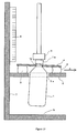
FIG. 17 is a diagram for explaining an example of the apparatus for testing the water hammer strength disclosed inPTL 1, showing a state in which aweight 5 has been dropped. - In this test apparatus, a
base stage 6, apost 7, and afixing stage 2 are formed as a single component. Fourcushion members 3 are disposed around a through-hole 2a in thefixing stage 2, andholding means 4 is placed thereon. Thecushion members 3 are made of elastic members composed of rubber, soft resin, or the like. The holding means holds abottle 1 that is filled with content and sealed with a cap 1b at a position above the center of gravity thereof (in this case, below abead 1a) and suspends the bottle in the air. Theweight 5 is provided above the cap 1b of thebottle 1. - When the
weight 5 is dropped onto the cap 1b of the bottle, thecushion members 3 are compressed and deformed due to the impact, and thebottle 1 is abruptly pushed downward, causing a water hammer effect. - At this time, because the
cushion members 3 are very soft, the compression and deformation thereof do not always occur in the vertical direction, and, as shown inFIG. 17 , middle parts or the like may be deformed in the horizontal direction (out-of-plane deformation). Because the extent of the out-of-plane deformation usually differs among the cushion members, thebottle 1 may be inclined, as shown inFIG. 17 . Furthermore, thebottle 1 is sometimes significantly inclined, causing thecushion members 3 to move (in a direction of arrow A) or jump out of the apparatus. - It cannot be said that the measured water hammer strength is correct if the bottle is significantly inclined or if the
cushion members 3 jump out of the apparatus when theweight 5 is dropped. Thus, in such a case, the cushion members have to be returned to the original positions and the measurement has to be performed again. - An object of the present invention is to prevent the bottle from being inclined when the
weight 5 is dropped and to prevent thecushion members 3 from moving due to the impact, thereby enabling efficient and correct measurement of the water hammer strength. - The present invention is an apparatus for testing the water hammer strength as defined in the
claims
wherein push-down means for forcibly pushing the holding means downward is provided, and wherein the cushion member is compressed and deformed by the push-down means. - By compressing and deforming the cushion member in advance using push-down means, the cushion member becomes less susceptible to out-of-plane deformation when the
weight 5 is dropped. As a result, the inclination of the bottle is considerably reduced. The movement of the cushion member is also reduced. - The push-down means may have any mechanism as long as it can forcibly push the holding means downward. Besides the mechanism disclosed in
Claim 2 below, push-down means utilizing a known mechanism, such as a clamp or a vice, may be employed. - More specifically, the push-down means may be a bolt screwed to the fixing stage from a top surface side of the holding means.
- By providing a bolt hole in the holding means, by providing a female screw hole in the fixing stage, and by screwing the bolt to the fixing stage from the top surface side of the holding means, it is possible to easily push down the holding means to compress and deform the cushion member. The extent by which the holding means is pushed downward may be easily adjusted by changing the tightness of the bolt.
- The cushion member may be formed of a plurality of cushion bodies bonded together with a non-cushioning plate therebetween.
- By doing so, the cushion member becomes even less susceptible to out-of-plane deformation when the
weight 5 is dropped, and, as a result, the inclination of the bottle is further reduced, and the movement of the cushion member is also further reduced. - Examples of the material of the non-cushioning plate include plastic, metal, and wood, which are less likely to be deformed than the cushion member.
- According to the invention a non-slip sheet is disposed between the fixing stage and the cushion member and between the cushion member and the holding means.
- Because the cushion member experiences significant deformation during the tests, the cushion member is deteriorated (cause cracks) after being subjected to impact several hundreds of times. Thus, the cushion member is an expendable member that requires replacement every time it is deteriorated. Therefore, the cushion member cannot be securely bonded to the fixing stage and the holding means. To prevent the cushion member from falling off, a non-slip sheet having a high coefficient of friction may be disposed between the fixing stage and the cushion member and between the cushion member and the holding means.
- By doing so, the cushion member becomes even less likely to move when the
weight 5 is dropped. - A sheet having good non-slip effect, such as a natural rubber sheet or a silicone rubber sheet, may be used as the non-slip sheet. The appropriate thickness of the sheet is from about 0.3 mm to 1 mm.
- Furthermore, the present invention is the apparatus for testing the water hammer strength according to
Claim 1, wherein the fixing stage and/or the holding means has a recess in a surface in contact with the cushion member, wherein the non-slip sheet is provided in the recess, and wherein the cushion member is embedded in the recess by 0.2 mm to 0.8 mm. - By doing so, the non-slip sheet and the cushion member do not come off from the recess, and the movement thereof can be prevented. Although the recess may be provided in only one of the fixing stage and the holding means, it is desirable that the recess be provided in both of them.
- The appropriate amount by which the upper end or the lower end of the cushion member is embedded in the recess (y in
FIG. 7 ) is from about 0.2 mm to 0.8 mm. If it is smaller than 0.2 mm, the cushion member may come off from the recess and move, and if it is larger than 0.8 mm, the cushion member may be cracked when it collides with the outer periphery of the recess, degrading the endurance of the cushion member, which is undesirable. - Note that the appropriate value for the distance between the cushion member and the outer periphery of the recess in the horizontal direction (x in
FIG. 7 ) is 0.1 mm to 0.5 mm. If it is smaller than 0.1 mm, due to the collision between the cushion member and the outer periphery of the recess, the cushion member tends to cause a crack at the corresponding part, and if it is larger than 0.5 mm, the cushion member moves significantly, which may allow the bottle to be inclined. - Furthermore, the present invention is the apparatus for testing the water hammer strength according to
Claim 3, wherein the cushion member is formed of a plurality of cushion bodies bonded together with a non-cushioning plate therebetween and non-cushioning plates bonded to the upper and lower ends thereof, wherein the fixing stage and/or the holding means has a recess in a surface in contact with the cushion member, and wherein the plate at the upper end and/or the plate at the lower end is disposed in the recess. - By bonding the non-cushioning plates to the upper and lower ends of the cushion member, the soft cushion body does not collide with the outer periphery of the recess when the cushion member moves, whereby the endurance of the cushion member is maintained. Furthermore, because the upper and lower ends of the cushion member are the non-cushioning plates, the cushion member will not move beyond the recess, whereby the movement of the cushion member is reliably limited.
- Furthermore, the present invention is the apparatus for testing the water hammer strength according to
Claim 4, wherein the cushion member is formed of a plurality of cushion bodies bonded together with a non-cushioning plate therebetween and non-cushioning plates bonded to the upper and lower ends thereof, wherein the plate at the upper end and/or the plate at the lower end has a hole in the top or bottom surface thereof, and wherein the fixing stage and/or the holding means has a projection that fits into the hole in the surface in contact with the cushion member. - Because the hole in the cushion member and the projection on the fixing stage or the holding means fit together, the movement of the cushion member is prevented.
- The fixing stage and the holding means do not need to have a recess and, thus, can be reduced in thickness. Advantageous Effects of Invention
- With the apparatus for testing the water hammer strength of the present invention, the cushion member is less susceptible to out-of-plane deformation and is less likely to move when the weight is dropped. Thus, it is possible to efficiently and correctly measure the water hammer strength.
-
- [
FIG. 1] FIG. 1 is a cross-sectional diagram for explaining a test apparatus according to an embodiment. - [
FIG. 2] FIG. 2 is a side view of a fixing stage, cushion members, and holding means. - [
FIG. 3] FIG. 3 is a plan view of the fixing stage, the cushion members, and the holding means. - [
FIG. 4] FIG. 4 is a cross-sectional diagram for explaining the test apparatus when the weight is dropped. - [
FIG. 5] FIG. 5 is a side view of the fixing stage, the cushion members, and the holding means when the weight is dropped. - [
FIG. 6] FIG. 6 is a vertical cross-sectional view of the relevant part of another embodiment. - [
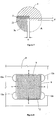
FIG. 7] FIG. 7 is an enlarged view of part A inFIG. 6 . - [
FIG. 8] FIG. 8 is a horizontal cross-sectional view of the relevant part of the embodiment inFIG. 6 . - [
FIG. 9] FIG. 9 is a vertical cross-sectional view of the relevant part of another embodiment. - [
FIG. 10] FIG. 10 is a horizontal cross-sectional view of the relevant part of the embodiment inFIG. 9 . - [
FIG. 11] FIG. 11 is a vertical cross-sectional view of the relevant part of another embodiment. - [
FIG. 12] FIG. 12 is a horizontal cross-sectional view of the relevant part of the embodiment inFIG. 11 . - [
FIG. 13] FIG. 13 is a vertical cross-sectional view of the relevant part of another embodiment. - [
FIG. 14] FIG. 14 is a side view of an exemplary cushion member. - [
FIG. 15] FIG. 15 is a side view of an exemplary cushion member. - [
FIG. 16] FIG. 16 is a side view of an exemplary cushion member. - [
FIG. 17] FIG. 17 is a cross-sectional diagram for explaining a conventional test apparatus. - [
FIG. 18] FIG. 18 is a diagram for explaining a method of testing packaged goods. -
FIGS. 1 to 5 relate to a test apparatus according to an embodiment. Abase stage 6, apost 7, and a fixingstage 2 are formed as a single component by processing a steel plate. Thepost 7 stands upright from thebase stage 6 so as to form an L shape, and the fixingstage 2 is formed so as to project from the middle of thepost 7. The fixingstage 2 has a through-hole 2a into which a body of abottle 1 can be inserted. -
Cushion members 3 are placed at four corners around the through-hole 2a in the fixingstage 2, and holding means 4 is placed thereon. - As shown in
FIG. 14 , eachcushion member 3 is formed of twocushion bodies 3a and aplate 3b disposed therebetween, which are securely bonded together. Thecushion bodies 3a are made of elastic members composed of rubber, soft resin, or the like. In this case, thecushion bodies 3a are made of soft gel-like members mainly composed of silicone (JIS K 2207, with a penetration of 55 and a Young's modulus of 119.5kPa) and having a size of 20 mm × 20 mm × 10 mm. Theplate 3b is made of a non-cushioning material less likely to be deformed than thecushion bodies 3a. Although non-cushioning plastic (i.e., plastic containing no foaming agent), metal, or a wood plate may be used, theplate 3b in this case is made of polycarbonate and has a size of 24 mm × 24 mm × 2 mm. -
Non-slip sheets 9 are disposed between the fixingstage 2 and thecushion members 3, and between thecushion members 3 and the holding means 4. Thenon-slip sheets 9 are silicone rubber sheets having a thickness of 0.5 mm. Thenon-slip sheets 9 are bonded to the fixingstage 2 and the holding means 4. - The holding means 4 holds the
bottle 1 filled with content and sealed with a cap at a position above the center of gravity thereof so as to suspend the bottle in the air. The material and shape of the holding means 4 are not specifically limited as long as it can securely hold thebottle 1 and it can be placed on thecushion members 3. For example, although the holding means 4 having various mechanisms, as disclosed inPTL 1, may be used, these mechanisms are omitted in the drawings of the present invention, and theglass bottle 1 is supported at a part immediately below thebead 1a by a through-hole 4a provided in the central part. - Although it is only necessary that the
bottle 1 filled with content and sealed with a cap is held at a position above the center of gravity thereof, it is most desirable that thebottle 1 be held at a neck (immediately below a mouth or the bead). - The holding means 4 has two bolt holes, and the fixing
stage 2 has corresponding two female screw holes. By screwingbolts 10 with the female screw holes in the fixingstage 2 from the top surface side of the holding means 4, thecushion members 3 are compressed and deformed (FIGS. 2 and 3 ).Nuts 11 prevent thebolts 10 from loosening. Thecushion members 3, which originally have a total thickness of 22 mm, are compressed to a thickness of 20.5 mm by forcibly pushing the holding means 4 downward with thebolts 10. - The
weight 5 is provided above the cap 1b of thebottle 1. Theweight 5, which is formed of a shaft 5b and a weight body 5a provided at the lower end thereof, is formed so as to protrude from thepost 7 and is capable of moving vertically upward and downward along a guide (not shown) having an insertion hole through which the shaft 5b extends. Theweight 5, held at a desired height by a stopper (not shown), falls right onto the cap 1b by removing the stopper. - The
post 7 is marked with ascale 8 so that the height of the weight can be easily known. - When the
weight 5 falls right onto the cap 1b, thecushion members 3 are deformed due to the drop energy thereof, and the holding means 4 and thebottle 1 are abruptly pushed downward (FIGS. 4 and5 ), causing a water hammer effect. - Because the
bolts 10 slide in the bolt holes in the holding means 4 at this time, the downward movement of the holding means 4 is not blocked. Furthermore, because thebolts 10 guide the downward movement of the holding means 4, the holding means 4 moves downward always vertically, and thus, is less likely to be inclined. - Because the
cushion members 3 are compressed and deformed in advance and theplate 3b is provided in the middle thereof, the out-of-plane deformation caused when subjected to the impact of theweight 5 is very small. Moreover, because thebolts 10 guide the downward movement of the holding means 4, the inclinations of the holding means 4 and thebottle 1 are very small. - Whereas the inclination of the
bottle 1 when the weight is dropped is 4° at the maximum and 2° on average with theconventional test apparatus 7, the inclination of thebottle 1 was reduced to a visually unrecognizable level in this embodiment. - In the measurement of the water hammer strength according to this embodiment, the weight is dropped several times while gradually increasing the drop energy, and the water hammer strength of the bottle is represented by the drop energy of the weight when the bottle is broken. The drop energy is adjusted by changing the weight and the drop height (the distance between the bottom surface of the weight and the top surface of the cap). The drop energy is mgh, where m is the mass of the weight, h is the drop height, and g is the acceleration of gravity.
-
FIGS. 6 to 8 show an embodiment in which the structure near the cushion members according to the embodiment inFIG. 1 to 5 is changed. The other structures are the same as those according to the embodiment inFIG. 1 to 5 . - Similarly to the above-described embodiment, each
cushion member 3 is formed of twocushion bodies 3a and aplate 3b disposed therebetween, which are securely bonded together (FIG. 14 ). - The
non-slip sheets 9 are silicone rubber sheets having a thickness of 0.5 mm and a size of 20.6 mm × 20.6 mm. - The fixing
stage 2 and the holding means 4 haverecesses reference numeral 12a inFIG. 8 are so-called milling cutter reliefs, which have to be provided to allow a milling cutter to cut the recesses. The shape of therecesses 12 in the fixingstage 2 and the shape ofrecesses 13 in the holding means 4 are exactly identical. - The
non-slip sheets 9 are placed in therecesses stage 2 and the holding means 4, and thecushion members 3 are disposed therebetween (FIG. 6 ). Thecushion members 3, which originally have a total thickness of 22 mm, are compressed to a thickness of 20.5 mm by forcibly pushing the holding means 4 downward with thebolts 10. - As shown in
FIG. 7 , thecushion members 3 are embedded in therecesses cushion members 3 and the outer peripheries of therecesses -
FIGS. 9 and 10 also show an embodiment in which the structure near the cushion members according to the embodiment inFIG. 1 to 5 is changed. The other structures are the same as those according to the embodiment inFIG. 1 to 5 . - As shown in
FIG. 15 , eachcushion member 3 is formed of twocushion bodies 3a and anon-cushioning plate 3b bonded therebetween, and thesame plates 3b securely bonded to the upper and lower ends thereof to form a single component. Thecushion bodies 3a have a size of 20 mm × 20 mm × 10 mm, and theplates 3b have a size of 22 mm × 22 mm × 2 mm. - The fixing
stage 2 and the holding means 4 have therecesses 12 having a depth of 1.5 mm and a size of 22.8 mm × 22.8 mm in the surface in contact with the cushion members. Semicircular portions of the recesses denoted by thereference numeral 12a inFIG. 8 are so-called milling cutter reliefs, which have to be provided to allow a milling cutter to cut the recesses. The shape of therecesses 12 in the fixingstage 2 and the shape ofrecesses 13 in the holding means 4 are exactly identical. - The appropriate value for the distance between the
plates 3b of the cushion members and the outer peripheries of therecesses - The
plates 3b at the ends of the cushion members are positioned in therecesses stage 2 and the holding means 4, and thecushion members 3 are disposed between the fixingstage 2 and the holding means 4 (FIG. 9 ). Thecushion members 3, which originally have a total thickness of 26 mm, are compressed to a thickness of 24.5 mm by forcibly pushing the holding means 4 downward with thebolts 10. -
FIGS. 11 and 12 also show an embodiment in which the structure near the cushion members according to the embodiment inFIG. 1 to 5 is changed. The other structures are the same as those according to the embodiment inFIG. 1 to 5 . - Although the
cushion members 3 are basically the same as those shown inFIGS. 9 and 10 , theplates 3b at the upper and lower ends have two round holes 14 (having a diameter of 3.5 mm). - The fixing
stage 2 and the holding means 4 have cylindrical projections 15 (having a diameter of 2.5 mm and a height of 1.5 mm) in the surface in contact with the cushion members, at positions corresponding to theholes 14. The appropriate value for the difference in diameter between theholes 14 and theprojections 15 is from about 0.1 mm to 1 mm. - The
cushion members 3 are disposed between the fixingstage 2 and the holding means 4. At this time, theprojections 15 loosely fit into the holes 14 (FIG. 11 ). Thecushion members 3, which originally have a total thickness of 26 mm, are compressed to a thickness of 24.5 mm by forcibly pushing the holding means 4 downward with thebolts 10. -
FIG. 13 also shows an embodiment in which the structure near the cushion members according to the embodiment inFIG. 1 to 5 is changed. The other structures are the same as those according to the embodiment inFIG. 1 to 5 . - In
FIG. 13 , although thecushion members 3 are basically the same as those shown inFIGS. 9 and 10 , only theplates 3b at the upper end has two round holes 14 (having a diameter of 3.5 mm). This configuration is the same as that of the plate at the upper end of the cushion member shown inFIG. 11 . - The fixing
stage 2 has therecesses 12 having a depth of 1.5 mm and a size of 22.8 mm × 22.8 mm in the surface in contact with the cushion members (top surface). This configuration is the same as that of the fixing stage shown inFIGS. 9 and 10 . - The holding means 4 has the cylindrical projections 15 (having a diameter of 2.5 mm and a height of 1.5 mm) in the surface in contact with the cushion members (bottom surface), at positions corresponding to the
holes 14. This configuration is the same as that of the holding means shown inFIG. 11 . - The
cushion members 3 are disposed between the fixingstage 2 and the holding means 4. Theplates 3b at the lower ends of thecushion members 3 are positioned in therecesses 12 in the fixingstage 2, and theprojections 15 loosely fit into theholes 14 at the upper ends of the cushion members. Thecushion members 3, which originally have a total thickness of 26 mm, are compressed to a thickness of 24.5 mm by forcibly pushing the holding means 4 downward with thebolts 10. - This embodiment employs the structure of the embodiment in
FIGS. 9 and 10 at the lower ends of the cushion members and the structure of the embodiment inFIGS. 11 and 12 at the upper ends. - Although each
cushion member 3 is formed of twocushion bodies 3a securely bonded together with anon-cushioning plate 3b therebetween in the above-described embodiment, the number of thecushion bodies 3a may be three or more. -
FIG. 16 shows an example in which threecushion bodies 3a are securely bonded together withnon-cushioning plates 3b therebetween. -
- 1:
- glass bottle
- 1a:
- bead
- 1b:
- cap
- 2:
- fixing stage
- 3:
- cushion member
- 3a:
- body
- 3b:
- plate
- 4:
- holding means
- 5:
- weight
- 6:
- base stage
- 7:
- post
- 8:
- scale
- 9:
- non-slip sheet
- 10:
- bolt
- 11:
- nut
- 12:
- recess
- 13:
- recess
- 14:
- hole
- 15:
- projection
- 20:
- drop testing machine
- 21:
- drop surface
- 22:
- sample stage
- 23:
- lower dummy
- 24:
- sample
- 25:
- upper dummy
Claims (5)
- An apparatus for testing the water hammer strength, the apparatus comprising:a fixing stage (2);a cushion member (3) placed on the fixing stage;holding means (4) that is placed on the cushion member and configured to hold a bottle filled with content and sealed with a cap at a position above the center of gravity thereof so as to suspend the bottle in the air; anda weight (5) configured to be dropped onto the cap to apply an impact to the bottle,wherein push-down means for forcibly pushing the holding means downward is provided, characterized in thatthe cushion member is configured to be compressed and deformed by the push-down means;a non-slip sheet is disposed between the fixing stage and the cushion member and between the cushion member and the holding means;the fixing stage and/or the holding means has a recess in a surface in contact with the cushion member;the non-slip sheet (9) is provided in the recess; andthe cushion member is embedded in the recess by 0.2 mm to 0.8 mm.
- The apparatus for testing the water hammer strength according to Claim 1,
wherein the cushion member is formed of a plurality of cushion bodies bonded together with a non-cushioning plate therebetween. - An apparatus for testing the water hammer strength, the apparatus comprising:a fixing stage (2);a cushion member (3) placed on the fixing stage;holding means (4) that is placed on the cushion member and configured to hold a bottle filled with content and sealed with a cap at a position above the center of gravity thereof so as to suspend the bottle in the air; anda weight (5) configured to be dropped onto the cap to apply an impact to the bottle,wherein push-down means for forcibly pushing the holding means downward is provided, characterized in thatthe cushion member is configured to be compressed and deformed by the push-down means;the cushion member is formed of a plurality of cushion bodies bonded together with a non-cushioning plate (3b) therebetween and non-cushioning plates bonded to the upper and lower ends thereof,the fixing stage and/or the holding means has a recess in a surface in contact with the cushion member, andthe plate at the upper end and/or the plate at the lower end is disposed in the recess.
- An apparatus for testing the water hammer strength, the apparatus comprising:a fixing stage (2);a cushion member (3) placed on the fixing stage;holding means (4) that is placed on the cushion member and configured to hold a bottle filled with content and sealed with a cap at a position above the center of gravity thereof so as to suspend the bottle in the air; anda weight (5) configured to be dropped onto the cap to apply an impact to the bottle,wherein push-down means for forcibly pushing the holding means downward is provided, characterized in thatthe cushion member is configured to be compressed and deformed by the push-down means;the cushion member is formed of a plurality of cushion bodies bonded together with a non-cushioning plate (3b) therebetween and non-cushioning plates bonded to the upper and lower ends thereof,the plate at the upper end and/or the plate at the lower end has a hole (14) in the top or bottom surface thereof, andthe fixing stage and/or the holding means has a projection (15) that fits into the hole in the surface in contact with the cushion member.
- The apparatus for testing the water hammer strength according to any one of claims 1 to 4,
wherein the push-down means is a bolt screwed to the fixing stage from a top surface side of the holding means.
Applications Claiming Priority (2)
| Application Number | Priority Date | Filing Date | Title |
|---|---|---|---|
| JP2010028566A JP4598153B1 (en) | 2009-07-22 | 2010-02-12 | Glass bottle water hammer strength test equipment |
| PCT/JP2010/053555 WO2011099169A1 (en) | 2010-02-12 | 2010-03-04 | Device for testing water hammer strength of glass bottle |
Publications (3)
| Publication Number | Publication Date |
|---|---|
| EP2535696A1 EP2535696A1 (en) | 2012-12-19 |
| EP2535696A4 EP2535696A4 (en) | 2017-09-27 |
| EP2535696B1 true EP2535696B1 (en) | 2018-09-05 |
Family
ID=44379985
Family Applications (1)
| Application Number | Title | Priority Date | Filing Date |
|---|---|---|---|
| EP10845761.5A Not-in-force EP2535696B1 (en) | 2010-02-12 | 2010-03-04 | Device for testing water hammer strength of glass bottle |
Country Status (3)
| Country | Link |
|---|---|
| EP (1) | EP2535696B1 (en) |
| CN (2) | CN104296955B (en) |
| WO (1) | WO2011099169A1 (en) |
Families Citing this family (2)
| Publication number | Priority date | Publication date | Assignee | Title |
|---|---|---|---|---|
| CN105466765A (en) * | 2016-01-29 | 2016-04-06 | 苏州莱测检测科技有限公司 | Impact testing machine buffer seat |
| CN114658793B (en) * | 2022-03-25 | 2023-02-03 | 北京航空航天大学 | Large-stroke anti-tilting synchronous buffering brake device |
Family Cites Families (7)
| Publication number | Priority date | Publication date | Assignee | Title |
|---|---|---|---|---|
| US3702563A (en) * | 1971-01-22 | 1972-11-14 | Anchor Hocking Corp | On-line simulated impact tester for glass containers |
| JPH08145837A (en) * | 1994-11-16 | 1996-06-07 | Sapporo Breweries Ltd | Sample holder for vibration tester and vibration test method |
| JP4068030B2 (en) * | 2003-08-21 | 2008-03-26 | 株式会社地盤試験所 | Pile rapid loading test equipment |
| CN2656993Y (en) * | 2003-10-23 | 2004-11-17 | 承德市金建检测仪器有限公司 | Cold-hot water cyclic tester for plastic pipeline system |
| CN1306255C (en) * | 2004-07-22 | 2007-03-21 | 苏州东菱振动试验仪器有限公司 | Composite table top structure of high acceleration impact test table |
| CN100365404C (en) * | 2005-06-10 | 2008-01-30 | 苏州东菱振动试验仪器有限公司 | Piston type high-acceleration impaction responding hammer for impaction testing table |
| JP4523631B2 (en) * | 2007-11-30 | 2010-08-11 | 東洋ガラス株式会社 | Water bottle strength test method and apparatus for glass bottle |
-
2010
- 2010-03-04 EP EP10845761.5A patent/EP2535696B1/en not_active Not-in-force
- 2010-03-04 WO PCT/JP2010/053555 patent/WO2011099169A1/en not_active Ceased
- 2010-03-04 CN CN201410602149.7A patent/CN104296955B/en not_active Expired - Fee Related
- 2010-03-04 CN CN201080063508.6A patent/CN102753953B/en not_active Expired - Fee Related
Non-Patent Citations (1)
| Title |
|---|
| None * |
Also Published As
| Publication number | Publication date |
|---|---|
| EP2535696A1 (en) | 2012-12-19 |
| CN102753953B (en) | 2015-04-22 |
| CN102753953A (en) | 2012-10-24 |
| EP2535696A4 (en) | 2017-09-27 |
| WO2011099169A1 (en) | 2011-08-18 |
| CN104296955B (en) | 2017-04-12 |
| CN104296955A (en) | 2015-01-21 |
Similar Documents
| Publication | Publication Date | Title |
|---|---|---|
| US9021858B2 (en) | Apparatus for testing water hammer strength of glass bottle | |
| US8402810B2 (en) | Method and apparatus for testing water hammer strength of glass bottle | |
| US9909950B2 (en) | Method and apparatus for inspecting resin shock absorber | |
| CN101365410B (en) | Weighing auxiliary equipment for packaging machines | |
| CN103796945A (en) | Method for determining the intactness and leaktightness of containers in filling plants | |
| EP2535696A1 (en) | Device for testing water hammer strength of glass bottle | |
| CN103562463B (en) | For the measuring system of stake | |
| EP2685235A1 (en) | Machine for testing cushioning material for packaging | |
| KR20110092017A (en) | Jig device for flat panel display panel and durability test method using the same | |
| RU80562U1 (en) | Shockproof Scales | |
| JP4523631B2 (en) | Water bottle strength test method and apparatus for glass bottle | |
| JP4925380B1 (en) | Glass bottle water hammer strength test equipment | |
| CN201945519U (en) | Testing apparatus for testing creep property of cushioning material | |
| JP7492681B2 (en) | How to measure the strength of tempered glass | |
| CN117233422A (en) | Overload protection method and device for acceleration sensor | |
| CN1485604A (en) | Rocker arm testing machine and testing method thereof | |
| CN204575287U (en) | A kind of compression-resistant testing machine for carton | |
| KR102778208B1 (en) | Drop tester with automatic rotation device | |
| CN220752150U (en) | Overload protection device for acceleration sensor | |
| CN204214727U (en) | Carton padded coaming creep proving installation | |
| TWM471035U (en) | Apparatus for testing substrate strength | |
| CN218938026U (en) | Ball falling impact experimental device for glass | |
| CN214040477U (en) | Weight tray for calibrating pressure gauge | |
| CN211696869U (en) | Battery bulb falling test device | |
| CN101097178A (en) | Measuring aid holder of impacting test |
Legal Events
| Date | Code | Title | Description |
|---|---|---|---|
| PUAI | Public reference made under article 153(3) epc to a published international application that has entered the european phase |
Free format text: ORIGINAL CODE: 0009012 |
|
| 17P | Request for examination filed |
Effective date: 20120905 |
|
| AK | Designated contracting states |
Kind code of ref document: A1 Designated state(s): AT BE BG CH CY CZ DE DK EE ES FI FR GB GR HR HU IE IS IT LI LT LU LV MC MK MT NL NO PL PT RO SE SI SK SM TR |
|
| DAX | Request for extension of the european patent (deleted) | ||
| RA4 | Supplementary search report drawn up and despatched (corrected) |
Effective date: 20170825 |
|
| RIC1 | Information provided on ipc code assigned before grant |
Ipc: G01N 3/303 20060101AFI20170821BHEP |
|
| GRAP | Despatch of communication of intention to grant a patent |
Free format text: ORIGINAL CODE: EPIDOSNIGR1 |
|
| STAA | Information on the status of an ep patent application or granted ep patent |
Free format text: STATUS: GRANT OF PATENT IS INTENDED |
|
| INTG | Intention to grant announced |
Effective date: 20180329 |
|
| GRAS | Grant fee paid |
Free format text: ORIGINAL CODE: EPIDOSNIGR3 |
|
| GRAA | (expected) grant |
Free format text: ORIGINAL CODE: 0009210 |
|
| STAA | Information on the status of an ep patent application or granted ep patent |
Free format text: STATUS: THE PATENT HAS BEEN GRANTED |
|
| RAP1 | Party data changed (applicant data changed or rights of an application transferred) |
Owner name: TOYO GLASS CO., LTD. |
|
| RIN1 | Information on inventor provided before grant (corrected) |
Inventor name: OHYA YUUICHI Inventor name: SAITOH SHINJI Inventor name: UEDA YOSUKE Inventor name: YAMAGUCHI JOHSHIROH |
|
| AK | Designated contracting states |
Kind code of ref document: B1 Designated state(s): AT BE BG CH CY CZ DE DK EE ES FI FR GB GR HR HU IE IS IT LI LT LU LV MC MK MT NL NO PL PT RO SE SI SK SM TR |
|
| REG | Reference to a national code |
Ref country code: GB Ref legal event code: FG4D |
|
| REG | Reference to a national code |
Ref country code: CH Ref legal event code: EP |
|
| REG | Reference to a national code |
Ref country code: AT Ref legal event code: REF Ref document number: 1038392 Country of ref document: AT Kind code of ref document: T Effective date: 20180915 |
|
| REG | Reference to a national code |
Ref country code: IE Ref legal event code: FG4D |
|
| REG | Reference to a national code |
Ref country code: DE Ref legal event code: R096 Ref document number: 602010053437 Country of ref document: DE |
|
| REG | Reference to a national code |
Ref country code: NL Ref legal event code: FP |
|
| REG | Reference to a national code |
Ref country code: LT Ref legal event code: MG4D |
|
| PG25 | Lapsed in a contracting state [announced via postgrant information from national office to epo] |
Ref country code: FI Free format text: LAPSE BECAUSE OF FAILURE TO SUBMIT A TRANSLATION OF THE DESCRIPTION OR TO PAY THE FEE WITHIN THE PRESCRIBED TIME-LIMIT Effective date: 20180905 Ref country code: LT Free format text: LAPSE BECAUSE OF FAILURE TO SUBMIT A TRANSLATION OF THE DESCRIPTION OR TO PAY THE FEE WITHIN THE PRESCRIBED TIME-LIMIT Effective date: 20180905 Ref country code: SE Free format text: LAPSE BECAUSE OF FAILURE TO SUBMIT A TRANSLATION OF THE DESCRIPTION OR TO PAY THE FEE WITHIN THE PRESCRIBED TIME-LIMIT Effective date: 20180905 Ref country code: GR Free format text: LAPSE BECAUSE OF FAILURE TO SUBMIT A TRANSLATION OF THE DESCRIPTION OR TO PAY THE FEE WITHIN THE PRESCRIBED TIME-LIMIT Effective date: 20181206 Ref country code: NO Free format text: LAPSE BECAUSE OF FAILURE TO SUBMIT A TRANSLATION OF THE DESCRIPTION OR TO PAY THE FEE WITHIN THE PRESCRIBED TIME-LIMIT Effective date: 20181205 Ref country code: BG Free format text: LAPSE BECAUSE OF FAILURE TO SUBMIT A TRANSLATION OF THE DESCRIPTION OR TO PAY THE FEE WITHIN THE PRESCRIBED TIME-LIMIT Effective date: 20181205 |
|
| REG | Reference to a national code |
Ref country code: ES Ref legal event code: FG2A Ref document number: 2699831 Country of ref document: ES Kind code of ref document: T3 Effective date: 20190213 |
|
| REG | Reference to a national code |
Ref country code: AT Ref legal event code: MK05 Ref document number: 1038392 Country of ref document: AT Kind code of ref document: T Effective date: 20180905 |
|
| PG25 | Lapsed in a contracting state [announced via postgrant information from national office to epo] |
Ref country code: HR Free format text: LAPSE BECAUSE OF FAILURE TO SUBMIT A TRANSLATION OF THE DESCRIPTION OR TO PAY THE FEE WITHIN THE PRESCRIBED TIME-LIMIT Effective date: 20180905 Ref country code: LV Free format text: LAPSE BECAUSE OF FAILURE TO SUBMIT A TRANSLATION OF THE DESCRIPTION OR TO PAY THE FEE WITHIN THE PRESCRIBED TIME-LIMIT Effective date: 20180905 |
|
| PG25 | Lapsed in a contracting state [announced via postgrant information from national office to epo] |
Ref country code: CZ Free format text: LAPSE BECAUSE OF FAILURE TO SUBMIT A TRANSLATION OF THE DESCRIPTION OR TO PAY THE FEE WITHIN THE PRESCRIBED TIME-LIMIT Effective date: 20180905 Ref country code: RO Free format text: LAPSE BECAUSE OF FAILURE TO SUBMIT A TRANSLATION OF THE DESCRIPTION OR TO PAY THE FEE WITHIN THE PRESCRIBED TIME-LIMIT Effective date: 20180905 Ref country code: PL Free format text: LAPSE BECAUSE OF FAILURE TO SUBMIT A TRANSLATION OF THE DESCRIPTION OR TO PAY THE FEE WITHIN THE PRESCRIBED TIME-LIMIT Effective date: 20180905 Ref country code: EE Free format text: LAPSE BECAUSE OF FAILURE TO SUBMIT A TRANSLATION OF THE DESCRIPTION OR TO PAY THE FEE WITHIN THE PRESCRIBED TIME-LIMIT Effective date: 20180905 Ref country code: AT Free format text: LAPSE BECAUSE OF FAILURE TO SUBMIT A TRANSLATION OF THE DESCRIPTION OR TO PAY THE FEE WITHIN THE PRESCRIBED TIME-LIMIT Effective date: 20180905 Ref country code: IS Free format text: LAPSE BECAUSE OF FAILURE TO SUBMIT A TRANSLATION OF THE DESCRIPTION OR TO PAY THE FEE WITHIN THE PRESCRIBED TIME-LIMIT Effective date: 20190105 |
|
| PG25 | Lapsed in a contracting state [announced via postgrant information from national office to epo] |
Ref country code: SK Free format text: LAPSE BECAUSE OF FAILURE TO SUBMIT A TRANSLATION OF THE DESCRIPTION OR TO PAY THE FEE WITHIN THE PRESCRIBED TIME-LIMIT Effective date: 20180905 Ref country code: PT Free format text: LAPSE BECAUSE OF FAILURE TO SUBMIT A TRANSLATION OF THE DESCRIPTION OR TO PAY THE FEE WITHIN THE PRESCRIBED TIME-LIMIT Effective date: 20190105 Ref country code: SM Free format text: LAPSE BECAUSE OF FAILURE TO SUBMIT A TRANSLATION OF THE DESCRIPTION OR TO PAY THE FEE WITHIN THE PRESCRIBED TIME-LIMIT Effective date: 20180905 |
|
| REG | Reference to a national code |
Ref country code: DE Ref legal event code: R097 Ref document number: 602010053437 Country of ref document: DE |
|
| PLBE | No opposition filed within time limit |
Free format text: ORIGINAL CODE: 0009261 |
|
| STAA | Information on the status of an ep patent application or granted ep patent |
Free format text: STATUS: NO OPPOSITION FILED WITHIN TIME LIMIT |
|
| PG25 | Lapsed in a contracting state [announced via postgrant information from national office to epo] |
Ref country code: DK Free format text: LAPSE BECAUSE OF FAILURE TO SUBMIT A TRANSLATION OF THE DESCRIPTION OR TO PAY THE FEE WITHIN THE PRESCRIBED TIME-LIMIT Effective date: 20180905 |
|
| 26N | No opposition filed |
Effective date: 20190606 |
|
| PG25 | Lapsed in a contracting state [announced via postgrant information from national office to epo] |
Ref country code: SI Free format text: LAPSE BECAUSE OF FAILURE TO SUBMIT A TRANSLATION OF THE DESCRIPTION OR TO PAY THE FEE WITHIN THE PRESCRIBED TIME-LIMIT Effective date: 20180905 |
|
| PG25 | Lapsed in a contracting state [announced via postgrant information from national office to epo] |
Ref country code: MC Free format text: LAPSE BECAUSE OF FAILURE TO SUBMIT A TRANSLATION OF THE DESCRIPTION OR TO PAY THE FEE WITHIN THE PRESCRIBED TIME-LIMIT Effective date: 20180905 |
|
| REG | Reference to a national code |
Ref country code: CH Ref legal event code: PL |
|
| PG25 | Lapsed in a contracting state [announced via postgrant information from national office to epo] |
Ref country code: LU Free format text: LAPSE BECAUSE OF NON-PAYMENT OF DUE FEES Effective date: 20190304 |
|
| REG | Reference to a national code |
Ref country code: BE Ref legal event code: MM Effective date: 20190331 |
|
| PG25 | Lapsed in a contracting state [announced via postgrant information from national office to epo] |
Ref country code: LI Free format text: LAPSE BECAUSE OF NON-PAYMENT OF DUE FEES Effective date: 20190331 Ref country code: CH Free format text: LAPSE BECAUSE OF NON-PAYMENT OF DUE FEES Effective date: 20190331 Ref country code: IE Free format text: LAPSE BECAUSE OF NON-PAYMENT OF DUE FEES Effective date: 20190304 |
|
| PG25 | Lapsed in a contracting state [announced via postgrant information from national office to epo] |
Ref country code: BE Free format text: LAPSE BECAUSE OF NON-PAYMENT OF DUE FEES Effective date: 20190331 |
|
| PG25 | Lapsed in a contracting state [announced via postgrant information from national office to epo] |
Ref country code: TR Free format text: LAPSE BECAUSE OF FAILURE TO SUBMIT A TRANSLATION OF THE DESCRIPTION OR TO PAY THE FEE WITHIN THE PRESCRIBED TIME-LIMIT Effective date: 20180905 |
|
| PGFP | Annual fee paid to national office [announced via postgrant information from national office to epo] |
Ref country code: IT Payment date: 20200306 Year of fee payment: 11 Ref country code: DE Payment date: 20200325 Year of fee payment: 11 Ref country code: GB Payment date: 20200318 Year of fee payment: 11 Ref country code: NL Payment date: 20200319 Year of fee payment: 11 |
|
| PG25 | Lapsed in a contracting state [announced via postgrant information from national office to epo] |
Ref country code: MT Free format text: LAPSE BECAUSE OF NON-PAYMENT OF DUE FEES Effective date: 20190304 |
|
| PGFP | Annual fee paid to national office [announced via postgrant information from national office to epo] |
Ref country code: FR Payment date: 20200310 Year of fee payment: 11 |
|
| PGFP | Annual fee paid to national office [announced via postgrant information from national office to epo] |
Ref country code: ES Payment date: 20200416 Year of fee payment: 11 |
|
| REG | Reference to a national code |
Ref country code: DE Ref legal event code: R082 Ref document number: 602010053437 Country of ref document: DE Representative=s name: HL KEMPNER PATENTANWALT, RECHTSANWALT, SOLICIT, DE |
|
| PG25 | Lapsed in a contracting state [announced via postgrant information from national office to epo] |
Ref country code: CY Free format text: LAPSE BECAUSE OF FAILURE TO SUBMIT A TRANSLATION OF THE DESCRIPTION OR TO PAY THE FEE WITHIN THE PRESCRIBED TIME-LIMIT Effective date: 20180905 |
|
| PG25 | Lapsed in a contracting state [announced via postgrant information from national office to epo] |
Ref country code: HU Free format text: LAPSE BECAUSE OF FAILURE TO SUBMIT A TRANSLATION OF THE DESCRIPTION OR TO PAY THE FEE WITHIN THE PRESCRIBED TIME-LIMIT; INVALID AB INITIO Effective date: 20100304 |
|
| REG | Reference to a national code |
Ref country code: DE Ref legal event code: R119 Ref document number: 602010053437 Country of ref document: DE |
|
| REG | Reference to a national code |
Ref country code: NL Ref legal event code: MM Effective date: 20210401 |
|
| GBPC | Gb: european patent ceased through non-payment of renewal fee |
Effective date: 20210304 |
|
| PG25 | Lapsed in a contracting state [announced via postgrant information from national office to epo] |
Ref country code: FR Free format text: LAPSE BECAUSE OF NON-PAYMENT OF DUE FEES Effective date: 20210331 Ref country code: GB Free format text: LAPSE BECAUSE OF NON-PAYMENT OF DUE FEES Effective date: 20210304 Ref country code: DE Free format text: LAPSE BECAUSE OF NON-PAYMENT OF DUE FEES Effective date: 20211001 Ref country code: NL Free format text: LAPSE BECAUSE OF NON-PAYMENT OF DUE FEES Effective date: 20210401 |
|
| PG25 | Lapsed in a contracting state [announced via postgrant information from national office to epo] |
Ref country code: IT Free format text: LAPSE BECAUSE OF NON-PAYMENT OF DUE FEES Effective date: 20210304 |
|
| REG | Reference to a national code |
Ref country code: ES Ref legal event code: FD2A Effective date: 20220523 |
|
| PG25 | Lapsed in a contracting state [announced via postgrant information from national office to epo] |
Ref country code: MK Free format text: LAPSE BECAUSE OF FAILURE TO SUBMIT A TRANSLATION OF THE DESCRIPTION OR TO PAY THE FEE WITHIN THE PRESCRIBED TIME-LIMIT Effective date: 20180905 |
|
| PG25 | Lapsed in a contracting state [announced via postgrant information from national office to epo] |
Ref country code: ES Free format text: LAPSE BECAUSE OF NON-PAYMENT OF DUE FEES Effective date: 20210305 |