EP2535681A1 - Device for estimating the depth of elements of a 3D scene - Google Patents
Device for estimating the depth of elements of a 3D scene Download PDFInfo
- Publication number
- EP2535681A1 EP2535681A1 EP12171189A EP12171189A EP2535681A1 EP 2535681 A1 EP2535681 A1 EP 2535681A1 EP 12171189 A EP12171189 A EP 12171189A EP 12171189 A EP12171189 A EP 12171189A EP 2535681 A1 EP2535681 A1 EP 2535681A1
- Authority
- EP
- European Patent Office
- Prior art keywords
- pixels
- pixel
- light
- scene
- lens
- Prior art date
- Legal status (The legal status is an assumption and is not a legal conclusion. Google has not performed a legal analysis and makes no representation as to the accuracy of the status listed.)
- Granted
Links
Images

Classifications
-
- G—PHYSICS
- G01—MEASURING; TESTING
- G01B—MEASURING LENGTH, THICKNESS OR SIMILAR LINEAR DIMENSIONS; MEASURING ANGLES; MEASURING AREAS; MEASURING IRREGULARITIES OF SURFACES OR CONTOURS
- G01B11/00—Measuring arrangements characterised by the use of optical techniques
- G01B11/02—Measuring arrangements characterised by the use of optical techniques for measuring length, width or thickness
- G01B11/026—Measuring arrangements characterised by the use of optical techniques for measuring length, width or thickness by measuring distance between sensor and object
-
- H—ELECTRICITY
- H04—ELECTRIC COMMUNICATION TECHNIQUE
- H04N—PICTORIAL COMMUNICATION, e.g. TELEVISION
- H04N13/00—Stereoscopic video systems; Multi-view video systems; Details thereof
-
- G—PHYSICS
- G02—OPTICS
- G02B—OPTICAL ELEMENTS, SYSTEMS OR APPARATUS
- G02B13/00—Optical objectives specially designed for the purposes specified below
- G02B13/22—Telecentric objectives or lens systems
-
- G—PHYSICS
- G06—COMPUTING OR CALCULATING; COUNTING
- G06T—IMAGE DATA PROCESSING OR GENERATION, IN GENERAL
- G06T15/00—Three-dimensional [3D] image rendering
-
- H—ELECTRICITY
- H04—ELECTRIC COMMUNICATION TECHNIQUE
- H04N—PICTORIAL COMMUNICATION, e.g. TELEVISION
- H04N13/00—Stereoscopic video systems; Multi-view video systems; Details thereof
- H04N13/20—Image signal generators
- H04N13/271—Image signal generators wherein the generated image signals comprise depth maps or disparity maps
Definitions
- the invention relates to a method and a device for estimating the depth of objects of a scene using the focus of an optical system imaging the objects of said scene.
- One purpose of the invention is to propose an advantageous device for estimation of the depth of object elements distributed in a 3D scene. Consequently, the purpose of the invention is a device for estimation of the depth of object elements of a 3D scene comprising:
- the object elements correspond to object zones of the scene for which the size and the position in the scene are defined in a way that they can be imaged onto one of the pixels of the light sensor.
- the focus is adjusted in a way to obtain the maximum flow on this pixel.
- the light flow can light up other pixels of the sensor, which can interfere with the focus adjustment process.
- the optical system also comprises 1) a telecentric relay imaging system positioned approximately in the plane of the image of said lens, able to relay the image of said elements onto said pixelatedlight sensor via a system of micro lenses, and 2) a light spatial modulator, also pixelated, attached to the input of said relay imaging system, where the optical axis of each micro lens passes through the centre of a different pixel of said bit mapped light sensor and through the centre of a different pixel of said light spatial modulator, where each micro lens is able, in combination with said relay imaging system and said lens, to image an object element of the scene onto the pixel of said pixelated light sensor that is situated on the optical axis of the micro lens, through the pixel of said light spatial modulator that is also situated on the optical axis of the micro lens.
- a telecentric relay imaging system positioned approximately in the plane of the image of said lens, able to relay the image of said elements onto said pixelatedlight sensor via a system of micro lenses
- a light spatial modulator also pixelated
- said depth estimation device also comprises means to control the pixels of the light spatial modulator so that each of said pixels passes successively into the passing state while all the other pixels of said modulator are in the blocking state.
- said depth estimation device also comprises means to control the pixels of the light spatial modulator so that, in each group, a pixel is always in the passing state while all the other pixels of the same group are in the blocking state, so that, in each group, each pixel passes successively into the passing state.
- each of said groups comprises the same number of pixels.
- the pixels are ordered geometrically in the same way, and the means to control the pixels of the light spatial modulator are adapted so that, in each group, each pixel passes successively into the passing state in the same geometric order.
- each group contains 3x3 pixels.
- the device for estimation of the depth may also be used to capture an image of the scene.
- the pixels of the light sensor which are used to estimate the depth may be subdivided into numerous subpixels according to the required definition of the images to capture.
- position A the same object of a 3D scene is positioned at two different depths: position A and position B.
- the simplified depth estimation device comprises:
- the bit mapped light sensor 2 here comprises a single pixel of a size corresponding approximately to that of the image of an object element of the scene situated on the optical axis of the lens, when the focusing of the optical system on this element is carried out.
- this lighting zone of the unique pixel of the sensor shrinks so that the light intensity captured by the pixel increases in accordance with the curve of figure 2 .
- the light intensity is at a maximum.
- the light intensity on this pixel begins to diminish according to the curve of figure 2 .
- the position A of the object element that corresponds to the maximum of light streams captured by the single pixel of the sensor 2 is considered as the focus position of this element on the sensor.
- This characteristic is one of the bases of the invention.
- the depth estimation device thus comprises means for adjusting the focus on an object element whose depth is to be evaluated, that are able to adjust the focus by fixing on the maximum of light streams that come from this element and that are captured by the sensor 2.
- the focus was carried out above by variation of the position of the object, but the same effect is obtained by varying the position of the lens or the position of lenses of the objective as is done for the usual shot objectives.
- the depth estimation device also comprises means able to deduce the depth of the object element of the adjustment of the focus that has just been described. These means can be based on a depth calibration or be based on standard optical calculations based on the characteristics and position of components of the optical system. These means that are themselves known will thus not be described in detail.
- the depth estimation device is identical to the preceding device with the slight difference that the light sensor comprises a plurality of pixels 21, 22 preferably distributed uniformly, in a same image plane of the objective 1 as the single pixel of the sensor of the preceding device.
- the optical system previously described also comprises:
- this optical system is such that the optical axis of each micro-lens 41 (central position), 42, 43 passes through the centre of another pixel 21 (central position), 22, 23 of the bit mapped light sensor 2 and through the centre of another pixel 51 (central position), 52, 53 of the light spatial modulator 5. More specifically, this optical system is such that each micro-lens 41, 42, 43 is able, in combination with the relay imaging system 3 and the objective 1, to image another object element E1, E2, E3 of the scene on the pixel 21, 22, 23 of the bit mapped light sensor 2 that is situated on the optical axis of this micro-lens, via the pixel 51, 52, 53 of the light spatial modulator 5 that is also situated on the optical axis of this micro-lens.
- each pixel of the sensor has a size corresponding approximately to that of the image of an object element of the scene, when the focusing of the optical system on this element is carried out.
- Each pixel of the light spatial modulator 5 is for example a cell of liquid crystals, preferably bi-stable, that is to say having a passing state of the light and a blocking state of the light.
- the depth estimation device also comprises means to control the pixels 51, 52, 53 of the light spatial modulator 5 so that, as will be made clear in more detail later, each pixel passes successively into the passing state while all the others are in the blocking state.
- the pixel 51, 52, 53 of the modulator are successively put into passing state, the two others remaining in the blocking state.
- the optical system can focus on the element E1 as previously described using pixel 21 if the sensor 2, without be interfered with by the light coming from the other elements of the object, specifically E2 and E3, because the pixels 52 and 53 of the modulator 5 are in the blocking state.
- the disadvantage previously described in reference to figure 3 is avoided. From the adjustment of the focusing on the element E1, the depth of this element in the object space is then deduced.
- the focusing of the optical system on the element E2 can be carried out in the same way using the pixel 22 (respectively 23) of the sensor 2, without being interfered with by light from the other object elements because the other pixels of the modulator 5 are in the blocking state.
- the disadvantage previously described in reference to figure 3 is also avoided. From the adjustment of the focusing on the element E2, the depth of this element in the object space is then deduced.
- Figure 5 shows light intensity variations perceived by each pixel 21, 22, 23 of the sensor 2 during the preceding three successive cycles of variations in focusing.
- the incidence of "parasite” lighting from other object elements can be seen. It can be seen that this "parasite” lighting does not prevent the maximum lighting from being detected that correctly corresponds to the focus.
- the more the number of pixels of the sensor 2 and the modulator 5 of the depth estimation device is high the more the density of the meshing of elements in the object space is increased, that is to say that of the meshing of the depth map of the object space.
- the number of micro-lenses in the system 4 is increased in the same proportions.
- the duration required for a complete scanning of the object space corresponds to the number of pixels multiplied by the duration of a cycle of variation of the focusing. This scanning total duration can become prohibitive, particularly if the objects of the scene are susceptible to move during the depth estimation operation.
- the pixels of the light spatial modulator are distributed into several groups G1,....Gi, Gn of adjacent pixels.
- each group has the same number of pixels, here 3x3 pixels: P1 G1, ..., P3G1, ..., P7G1, ..., P9G1 for the first group G1, ..., P1 Gi, ..., P9Gi for the group Gi, ..., up to P1 GN, ..., P3GN, ..., P7GN, ..., P9GN for the last group GN.
- the means to control the pixels of the light spatial modulator 5 are adapted so that, in each group, a pixel is always in the passing state while the other pixels of the same group remain in the blocking state, and so that, in each group, each pixel passes successively into the passing state.
- the pixels are ordered according to the same predetermined geometric order in each group, and each pixel passes successively into the passing state according to a same order in each group. For example, in each group, it is first the first pixel that is in the passing state as in figure 6 , then the second in each group as in figure 7 , and so on.
- the procedure is as described for the first embodiment, with the following difference.
- the variations in light intensity captured by each of the pixels of the sensor that correspond to the pixels in the passing state of the modulator are recorded simultaneously.
- 9 curves are thus obtained of the type shown in figure 2 . From each curve recorded by a pixel, an adjustment of the focus is deduced corresponding to the maximum of captured light intensity, from which is estimated as previously the depth of the object element whose image was focused on this pixel.
- the number of focus variation cycles required for a complete scanning of the object space corresponds to the number of pixels in each group (here 9) and not the total number of pixels of the sensor, which advantageously enables the duration required for the acquisition of depth values of object elements of the 3D scene to be considerably reduced.
- the relay imaging system 3 is telecentric across the objective 1.
- the present invention that was described above on the basis of non-restrictive examples, extends to all embodiments covered by the claims hereafter.
Landscapes
- Physics & Mathematics (AREA)
- General Physics & Mathematics (AREA)
- Engineering & Computer Science (AREA)
- Multimedia (AREA)
- Computer Graphics (AREA)
- Theoretical Computer Science (AREA)
- Optics & Photonics (AREA)
- Signal Processing (AREA)
- Length Measuring Devices By Optical Means (AREA)
- Measurement Of Optical Distance (AREA)
- Image Processing (AREA)
- Image Analysis (AREA)
- Studio Devices (AREA)
- Testing, Inspecting, Measuring Of Stereoscopic Televisions And Televisions (AREA)
Abstract
- an optical system itself comprising a light sensor (2) with a plurality of pixels (21,22,23) and a lens (1) able to image the elements (E1,E2,E3) of the scene on one of the pixels of said light sensor,
- means to adjust the focus of the optical system onto any one of the elements of said scene that are able to adjust said focus by fixing on the maximum of light streams coming from this element and captured by one of the pixels of said bit mapped light sensor, and
- means suitable for deducing from the adjustment of said focus, the depth of said element, the optical system further comprising a telecentric relay imaging system (3) with microlenses (4) and a a spatial light modulator (5).
Description
- The invention relates to a method and a device for estimating the depth of objects of a scene using the focus of an optical system imaging the objects of said scene.
- The article by Paolo Favaro entitled "Depth from focus/defocus" published on 25 June 2002 (http://homepaaes.inf.ed.ac.uk/rbf/CVonline/LOCAL COPIES/FAVARO1/dfdtuto rial.html ) sums up the optical methods for the establishment of depth maps. This article indicates that methods based on optical focusing go through the dynamic changing of parameters of image estimation means during the depth evaluation process.
- The article by John Ens et al., published 02 February 1993 in the review "IEEE transactions on pattern analysis and machine intelligence", Vo1.15, N°2, and entitled "An investigation of methods for determining depth from focus" indicate that the distance calculation of different points of a scene is carried out via the modelling of effects that the focal parameters of a camera have on images captured by that camera in conditions of low field depth.
http://www.sc.ehu.es/ccwgrrom/transparencias/articulos-alumnos-doct-2002/iosu-larra%2596aga/00192482.pdf - One purpose of the invention is to propose an advantageous device for estimation of the depth of object elements distributed in a 3D scene. Consequently, the purpose of the invention is a device for estimation of the depth of object elements of a 3D scene comprising:
- an optical system itself comprising a light sensor including a plurality of pixels and a lens able to image the object elements of the scene on the pixels of said light sensor,
- means to adjust the focus of the optical system onto any one of the object elements of said scene, and
- means suitable for deducing the depth of said object element from the adjustment of said focus on said object element of said scene,
- The object elements correspond to object zones of the scene for which the size and the position in the scene are defined in a way that they can be imaged onto one of the pixels of the light sensor.
- In practice, when the focusing is carried out on an element of the scene, the light flow from this element reaches a single pixel of the light sensor, which is situated at the area where this element is imaged via the lens. According to the invention, the focus is adjusted in a way to obtain the maximum flow on this pixel. When there is noticeable deviation from the focus, the light flow can light up other pixels of the sensor, which can interfere with the focus adjustment process.
- Preferably, the optical system also comprises 1) a telecentric relay imaging system positioned approximately in the plane of the image of said lens, able to relay the image of said elements onto said pixelatedlight sensor via a system of micro lenses, and 2) a light spatial modulator, also pixelated, attached to the input of said relay imaging system,
where the optical axis of each micro lens passes through the centre of a different pixel of said bit mapped light sensor and through the centre of a different pixel of said light spatial modulator,
where each micro lens is able, in combination with said relay imaging system and said lens, to image an object element of the scene onto the pixel of said pixelated light sensor that is situated on the optical axis of the micro lens, through the pixel of said light spatial modulator that is also situated on the optical axis of the micro lens. - Preferably, said depth estimation device also comprises means to control the pixels of the light spatial modulator so that each of said pixels passes successively into the passing state while all the other pixels of said modulator are in the blocking state.
- Preferably, if the pixels of the light spatial modulator are distributed into a plurality of adjacent pixel groups, said depth estimation device also comprises means to control the pixels of the light spatial modulator so that, in each group, a pixel is always in the passing state while all the other pixels of the same group are in the blocking state, so that, in each group, each pixel passes successively into the passing state.
- Preferably, each of said groups comprises the same number of pixels.
- Preferably, in each group, the pixels are ordered geometrically in the same way, and the means to control the pixels of the light spatial modulator are adapted so that, in each group, each pixel passes successively into the passing state in the same geometric order.
- Preferably, each group contains 3x3 pixels.
- Advantageously, the device for estimation of the depth may also be used to capture an image of the scene. In such a situation, the pixels of the light sensor which are used to estimate the depth may be subdivided into numerous subpixels according to the required definition of the images to capture.
- The invention will be better understood upon reading the following description, provided as a non-restrictive example and referring to the annexed drawings wherein:
-
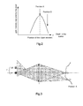
figure 1 diagrammatically shows the method for focusing that is used in the depth estimation device according to the invention, -
figure 2 shows the light intensity variation captured by a pixel of the sensor of the device according to the invention during focusing on the object element of the scene that corresponds to it, using the focusing method shown infigure 1 , -
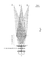
figure 3 shows the problem of interference of the lighting of a pixel of the sensor of the device used for focusing on an object element of the scene by light coming from another object element, -
figure 4 diagrammatically shows a preferred embodiment of a device for estimation of the depth of object elements of the 3D scene according to the invention, -
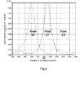
figure 5 shows, in an analogous manner tofigure 2 , the variation in light intensity captured by different pixels of the sensor of the device offigure 4 , during focusing on the object elements of the scene corresponding to them -
figure 6 shows an embodiment of the grouping of pixels of the light spatial modulator of the device offigure 4 , where, according to the invention, a single pixel in each group is in the "passing" state, -
figure 7 is identical tofigure 6 with the slight difference in that, in each group, another pixel has passed into the "passing" state, the other pixels being in the "blocking" state. - In reference to
figure 1 , this description will begin with a description of one of the general principles on which the method for measurement of depth is based according to the invention, using a simplified depth estimation device. - In this figure, the same object of a 3D scene is positioned at two different depths: position A and position B.
- The simplified depth estimation device comprises:
- an optical system comprising a
lens 1 and a bit mappedlight sensor 2 positioned on the optical axis of the lens that is able to image on thissensor 2 any object element of the scene at the instant that is situated on the optical axis of the lens, - means (not shown) to adjust the focusing of this optical system on this object element, and
- means (not shown) able to deduce the depth of said object element of the adjustment of the focusing on this element.
- The bit mapped
light sensor 2 here comprises a single pixel of a size corresponding approximately to that of the image of an object element of the scene situated on the optical axis of the lens, when the focusing of the optical system on this element is carried out. - Now will be described the method for focusing on which the invention is based. If an object of the scene is positioned in position B (object drawn in a broken line in
figure 1 ), the light streams coming from the object element that is situated on the optical axis light the unique pixel of thesensor 2 over a light zone that widely extends beyond that of the pixel of the sensor: seefigure 1 . - As the object is moved from position B towards position A along the optical axis, this lighting zone of the unique pixel of the sensor shrinks so that the light intensity captured by the pixel increases in accordance with the curve of
figure 2 . On arriving at position A (the object drawn in a solid line infigure 1 ), the light intensity is at a maximum. Following the displacement of the object in the same direction towards thelens 1, the light intensity on this pixel begins to diminish according to the curve offigure 2 . - The position A of the object element that corresponds to the maximum of light streams captured by the single pixel of the
sensor 2 is considered as the focus position of this element on the sensor. - This characteristic is one of the bases of the invention.
- According to the invention, the depth estimation device thus comprises means for adjusting the focus on an object element whose depth is to be evaluated, that are able to adjust the focus by fixing on the maximum of light streams that come from this element and that are captured by the
sensor 2. For the requirements of the explanation of the basic principle, the focus was carried out above by variation of the position of the object, but the same effect is obtained by varying the position of the lens or the position of lenses of the objective as is done for the usual shot objectives. - According to the invention, the depth estimation device also comprises means able to deduce the depth of the object element of the adjustment of the focus that has just been described. These means can be based on a depth calibration or be based on standard optical calculations based on the characteristics and position of components of the optical system. These means that are themselves known will thus not be described in detail.
- In reference to
figure 3 , a more complete embodiment will now be described, the problem that it poses and the solution that the invention provides. The depth estimation device is identical to the preceding device with the slight difference that the light sensor comprises a plurality ofpixels objective 1 as the single pixel of the sensor of the preceding device. - This arrangement now enables the depth to be evaluated, in the scene, not only of an object element situated on the optical axis as previously, this element E1 being imaged on the
central pixel 21 as previously described, but also object elements positioned outside of the optical axis, such as E2, these elements being imaged on another pixel of the same sensor such as thepixel 22. But, as can be seen infigure 3 , when the focus is carried out for the element E1 on thepixel 21 of thesensor 2, it is very far from the focus adjustment for the element E2 on thepixel 22 that corresponds to it, so that the light streams coming from the element E2 partly light thepixel 21, which interferes with the determination of the maximum light streams on this pixel and the estimation of the depth of the element E1. - In order to overcome this problem, it is proposed to improve the depth estimation device in the following way.
- According to this improvement, and in reference to
figure 4 , the optical system previously described also comprises: - a
relay imaging system 3 positioned approximately in the image plane of theobjective 1, able to relay to the image object elements of the scene on the bit mappedlight sensor 2 via a system of micro-lenses 4, - a light spatial modulator 5, also bit mapped, attached to the input, on the sensor side, of the
relay imaging system 3. - More specifically, this optical system is such that the optical axis of each micro-lens 41 (central position), 42, 43 passes through the centre of another pixel 21 (central position), 22, 23 of the bit mapped
light sensor 2 and through the centre of another pixel 51 (central position), 52, 53 of the light spatial modulator 5. More specifically, this optical system is such that each micro-lens 41, 42, 43 is able, in combination with therelay imaging system 3 and theobjective 1, to image another object element E1, E2, E3 of the scene on thepixel light sensor 2 that is situated on the optical axis of this micro-lens, via the pixel 51, 52, 53 of the light spatial modulator 5 that is also situated on the optical axis of this micro-lens. - Preferably each pixel of the sensor has a size corresponding approximately to that of the image of an object element of the scene, when the focusing of the optical system on this element is carried out.
- Each pixel of the light spatial modulator 5 is for example a cell of liquid crystals, preferably bi-stable, that is to say having a passing state of the light and a blocking state of the light.
- According to a first embodiment of this improved embodiment, the depth estimation device also comprises means to control the pixels 51, 52, 53 of the light spatial modulator 5 so that, as will be made clear in more detail later, each pixel passes successively into the passing state while all the others are in the blocking state.
- The method for focussing and depth estimation using this more complete device will now be described, applied to three object elements E1, E2 and E3, the element E1 is on the optical axis, the element E3 is above the axis, the element E2 is below the axis, these three elements can belong to the same object or to different objects.
- Using the control means of the light spatial modulator, the pixel 51, 52, 53 of the modulator are successively put into passing state, the two others remaining in the blocking state.
- When the pixel 51 is in the passing state (and the two others in the blocking state), the optical system can focus on the element E1 as previously described using
pixel 21 if thesensor 2, without be interfered with by the light coming from the other elements of the object, specifically E2 and E3, because the pixels 52 and 53 of the modulator 5 are in the blocking state. Thus the disadvantage previously described in reference tofigure 3 is avoided. From the adjustment of the focusing on the element E1, the depth of this element in the object space is then deduced. - Likewise, when the pixel 52 (respectively 53) is in the passing state, the focusing of the optical system on the element E2 (respectively E3) can be carried out in the same way using the pixel 22 (respectively 23) of the
sensor 2, without being interfered with by light from the other object elements because the other pixels of the modulator 5 are in the blocking state. Thus the disadvantage previously described in reference tofigure 3 is also avoided. From the adjustment of the focusing on the element E2, the depth of this element in the object space is then deduced. - Thus, by successively passing each pixel of the modulator into the passing state while maintaining the other pixels in the blocking state, it can be seen that the object space is scanned around the optical axis of the optical system, in a way to deduce the depth of each object element closest to the objective in this space.
-
Figure 5 shows light intensity variations perceived by eachpixel sensor 2 during the preceding three successive cycles of variations in focusing. In the lower part of the figure, for each pixel used for the focusing of an object element, the incidence of "parasite" lighting from other object elements can be seen. It can be seen that this "parasite" lighting does not prevent the maximum lighting from being detected that correctly corresponds to the focus. This illustrates the advantage of the improvement to the invention. The more the number of pixels of thesensor 2 and the modulator 5 of the depth estimation device is high, the more the density of the meshing of elements in the object space is increased, that is to say that of the meshing of the depth map of the object space. Obviously, the number of micro-lenses in the system 4 is increased in the same proportions. - In practice, given the number of pixels that are required to obtain a depth map sufficiently dense for a 3D scene, the duration required for a complete scanning of the object space corresponds to the number of pixels multiplied by the duration of a cycle of variation of the focusing. This scanning total duration can become prohibitive, particularly if the objects of the scene are susceptible to move during the depth estimation operation.
- The second embodiment of this improvement to the invention will now be presented that enables in addition this problem of scanning duration to be resolved.
- According to this embodiment and in reference to
figure 6 , the pixels of the light spatial modulator are distributed into several groups G1,....Gi, Gn of adjacent pixels. Preferably each group has the same number of pixels, here 3x3 pixels: P1 G1, ..., P3G1, ..., P7G1, ..., P9G1 for the first group G1, ..., P1 Gi, ..., P9Gi for the group Gi, ..., up to P1 GN, ..., P3GN, ..., P7GN, ..., P9GN for the last group GN. - The means to control the pixels of the light spatial modulator 5 are adapted so that, in each group, a pixel is always in the passing state while the other pixels of the same group remain in the blocking state, and so that, in each group, each pixel passes successively into the passing state. Preferably, the pixels are ordered according to the same predetermined geometric order in each group, and each pixel passes successively into the passing state according to a same order in each group. For example, in each group, it is first the first pixel that is in the passing state as in
figure 6 , then the second in each group as infigure 7 , and so on. - To implement the device according to this second embodiment, the procedure is as described for the first embodiment, with the following difference. When the pixels of the light spatial modulator are in the states shown in
figure 6 (black square = blocking state, white square = passing state), during a focusing variation cycle, the variations in light intensity captured by each of the pixels of the sensor that correspond to the pixels in the passing state of the modulator are recorded simultaneously. At each focus variation cycle, 9 curves are thus obtained of the type shown infigure 2 . From each curve recorded by a pixel, an adjustment of the focus is deduced corresponding to the maximum of captured light intensity, from which is estimated as previously the depth of the object element whose image was focused on this pixel. It continues in the same way when the pixels of the light spatial modulator pass into the states shown infigure 7 (black square = blocking state, white square = passing state), and so on until each pixel of each group has passed once into the passing state. Thus, the number of focus variation cycles required for a complete scanning of the object space corresponds to the number of pixels in each group (here 9) and not the total number of pixels of the sensor, which advantageously enables the duration required for the acquisition of depth values of object elements of the 3D scene to be considerably reduced. - More numerous groups of pixels can be used without departing from the invention, but it has be remarked that the number of nine pixels in each group, uniformly distributed in both directions, vertical and horizontal, best enables the scanning speed of the object space to be improved while limiting the lighting parasite risks between the different pixels of the sensor, as described previously.
- Preferably, the
relay imaging system 3 is telecentric across theobjective 1. The present invention, that was described above on the basis of non-restrictive examples, extends to all embodiments covered by the claims hereafter.
Claims (6)
- Device for estimating the depth of object elements of a 3D scene comprising:- an optical system itself comprising a light sensor (2) with a plurality of pixels (21, 22, 23) and a lens (1) able to image the object elements (E1, E2, E3) of the scene on the pixels of said light sensor,- means to adjust the focus of the optical system onto any one of the object elements of said scene that are able to adjust said focus by fixing on the maximum of light flow coming from said object element and captured by one of the pixels of said pixelated light sensor, and- means suitable for deducing the depth of said object element from the adjustment of said focus on said object element of said scene,
characterized in that:- said optical system also comprises 1) a telecentric relay imaging system positioned approximately in the plane of the image of said lens, able to relay the image of said object elements onto said pixelated light sensor via a system of micro-lenses, and 2) a light spatial modulator, also pixelated, attached to the input of said relay imaging system,
where the optical axis of each micro-lens passes through the centre of a different pixel of said bit mapped light sensor and through the centre of a different pixel of said light spatial modulator,
where each micro-lens is able, in combination with said relay imaging system and said lens (1), to image an object element of the scene onto the pixel of said bit mapped light sensor that is situated on the optical axis of the micro lens, through the pixel of said light spatial modulator that is also situated on the optical axis of the micro-lens. - Depth estimation device according to claim 1 characterized in that it also comprises the means to control the pixels (51, 52, 53) of the light spatial modulator (5) so that each of said pixels passes successively into the passing state while all the other pixels of said modulator are in the blocking state.
- Depth estimation device according to claim 1 characterized in that, if the pixels of the light spatial modulator are distributed into a plurality of adjacent pixel groups (G1, ..., Gi, ..., GN), it also comprises means to control the pixels of the light spatial modulator (5) so that, in each group, a pixel is always in the passing state while all the other pixels of the same group are in the blocking state, so that, in each group, each pixel passes successively into the passing state.
- Depth estimation device according to claim 3 characterized in that each of said groups comprises the same number of pixels.
- Depth estimation device according to claim 4 characterized in that, in each group, the pixels are ordered geometrically in the same way, and in that the means to control the pixels of the light spatial modulator (5) are adapted so that, in each group, each pixel passes successively into the passing state in the same geometric order.
- Depth estimation device according to any one of claims 4 to 5 characterized in that each group contains 3x3 pixels.
Applications Claiming Priority (1)
| Application Number | Priority Date | Filing Date | Title |
|---|---|---|---|
| FR1155330 | 2011-06-17 |
Publications (2)
| Publication Number | Publication Date |
|---|---|
| EP2535681A1 true EP2535681A1 (en) | 2012-12-19 |
| EP2535681B1 EP2535681B1 (en) | 2016-01-06 |
Family
ID=46172747
Family Applications (1)
| Application Number | Title | Priority Date | Filing Date |
|---|---|---|---|
| EP12171189.9A Active EP2535681B1 (en) | 2011-06-17 | 2012-06-07 | Device for estimating the depth of elements of a 3D scene |
Country Status (5)
| Country | Link |
|---|---|
| US (1) | US20120320160A1 (en) |
| EP (1) | EP2535681B1 (en) |
| JP (1) | JP2013029496A (en) |
| KR (1) | KR20120139587A (en) |
| CN (1) | CN102833569B (en) |
Families Citing this family (17)
| Publication number | Priority date | Publication date | Assignee | Title |
|---|---|---|---|---|
| WO2014198629A1 (en) | 2013-06-13 | 2014-12-18 | Basf Se | Detector for optically detecting at least one object |
| AU2014310703B2 (en) * | 2013-08-19 | 2018-09-27 | Basf Se | Optical detector |
| WO2015137635A1 (en) * | 2014-03-13 | 2015-09-17 | Samsung Electronics Co., Ltd. | Image pickup apparatus and method for generating image having depth information |
| CN106662636B (en) | 2014-07-08 | 2020-12-25 | 巴斯夫欧洲公司 | Detector for determining a position of at least one object |
| JP2018510320A (en) * | 2014-12-09 | 2018-04-12 | ビーエーエスエフ ソシエタス・ヨーロピアBasf Se | Optical detector |
| US11125880B2 (en) | 2014-12-09 | 2021-09-21 | Basf Se | Optical detector |
| WO2016120392A1 (en) | 2015-01-30 | 2016-08-04 | Trinamix Gmbh | Detector for an optical detection of at least one object |
| KR102311688B1 (en) | 2015-06-17 | 2021-10-12 | 엘지전자 주식회사 | Mobile terminal and method for controlling the same |
| KR102644439B1 (en) | 2015-07-17 | 2024-03-07 | 트리나미엑스 게엠베하 | Detector for optically detecting one or more objects |
| JP2019523562A (en) | 2016-07-29 | 2019-08-22 | トリナミクス ゲゼルシャフト ミット ベシュレンクテル ハフツング | Optical sensor and detector for optical detection |
| US11428787B2 (en) | 2016-10-25 | 2022-08-30 | Trinamix Gmbh | Detector for an optical detection of at least one object |
| CN109923372B (en) | 2016-10-25 | 2021-12-21 | 特里纳米克斯股份有限公司 | Infrared optical detector employing integrated filter |
| US11860292B2 (en) | 2016-11-17 | 2024-01-02 | Trinamix Gmbh | Detector and methods for authenticating at least one object |
| US11415661B2 (en) | 2016-11-17 | 2022-08-16 | Trinamix Gmbh | Detector for optically detecting at least one object |
| CN106454318B (en) * | 2016-11-18 | 2020-03-13 | 成都微晶景泰科技有限公司 | Stereoscopic imaging method and stereoscopic imaging device |
| CN110770555A (en) | 2017-04-20 | 2020-02-07 | 特里纳米克斯股份有限公司 | Optical detector |
| JP7237024B2 (en) | 2017-06-26 | 2023-03-10 | トリナミクス ゲゼルシャフト ミット ベシュレンクテル ハフツング | a detector for determining the position of at least one object |
Citations (2)
| Publication number | Priority date | Publication date | Assignee | Title |
|---|---|---|---|---|
| EP2214139A1 (en) * | 2009-01-30 | 2010-08-04 | Sony Corporation | Two-dimensional polynomial model for depth estimation based on two-picture matching |
| EP2239706A1 (en) * | 2008-01-15 | 2010-10-13 | Universidad De La Laguna | Method and camera for the real-time acquisition of visual information from three-dimensional scenes |
Family Cites Families (18)
| Publication number | Priority date | Publication date | Assignee | Title |
|---|---|---|---|---|
| JP3350918B2 (en) * | 1996-03-26 | 2002-11-25 | 株式会社高岳製作所 | Two-dimensional array confocal optical device |
| US5737084A (en) * | 1995-09-29 | 1998-04-07 | Takaoka Electric Mtg. Co., Ltd. | Three-dimensional shape measuring apparatus |
| CA2307315C (en) * | 1997-10-29 | 2011-04-05 | Calum Eric Macaulay | Apparatus and methods relating to spatially light modulated microscopy |
| DE60228940D1 (en) * | 2001-03-15 | 2008-10-30 | Amo Wavefront Sciences Llc | FIGURES FOR ILLUSTRATING AN OPTICAL SYSTEM |
| JP2006208407A (en) * | 2005-01-24 | 2006-08-10 | Olympus Medical Systems Corp | Stereoscopic microscope system |
| EP1941314A4 (en) * | 2005-10-07 | 2010-04-14 | Univ Leland Stanford Junior | MICROSCOPY ARRANGEMENTS AND TECHNIQUES |
| US7932993B2 (en) * | 2006-09-16 | 2011-04-26 | Wenhui Mei | Divided sub-image array scanning and exposing system |
| US7792423B2 (en) * | 2007-02-06 | 2010-09-07 | Mitsubishi Electric Research Laboratories, Inc. | 4D light field cameras |
| US20090262182A1 (en) * | 2007-10-15 | 2009-10-22 | The University Of Connecticut | Three-dimensional imaging apparatus |
| JP2009250685A (en) * | 2008-04-02 | 2009-10-29 | Sharp Corp | Distance measuring device and distance measuring method |
| KR101483714B1 (en) * | 2008-06-18 | 2015-01-16 | 삼성전자 주식회사 | Apparatus and method for capturing digital image |
| US8351031B2 (en) * | 2009-06-05 | 2013-01-08 | Spectral Sciences, Inc. | Single-shot spectral imager |
| US8345144B1 (en) * | 2009-07-15 | 2013-01-01 | Adobe Systems Incorporated | Methods and apparatus for rich image capture with focused plenoptic cameras |
| US8497934B2 (en) * | 2009-11-25 | 2013-07-30 | Massachusetts Institute Of Technology | Actively addressable aperture light field camera |
| US8400555B1 (en) * | 2009-12-01 | 2013-03-19 | Adobe Systems Incorporated | Focused plenoptic camera employing microlenses with different focal lengths |
| US8860835B2 (en) * | 2010-08-11 | 2014-10-14 | Inview Technology Corporation | Decreasing image acquisition time for compressive imaging devices |
| US8649024B2 (en) * | 2010-12-03 | 2014-02-11 | Zygo Corporation | Non-contact surface characterization using modulated illumination |
| US8237835B1 (en) * | 2011-05-19 | 2012-08-07 | Aeon Imaging, LLC | Confocal imaging device using spatially modulated illumination with electronic rolling shutter detection |
-
2012
- 2012-06-07 EP EP12171189.9A patent/EP2535681B1/en active Active
- 2012-06-13 JP JP2012134226A patent/JP2013029496A/en not_active Ceased
- 2012-06-15 KR KR1020120064290A patent/KR20120139587A/en not_active Withdrawn
- 2012-06-15 US US13/524,403 patent/US20120320160A1/en not_active Abandoned
- 2012-06-15 CN CN201210202107.5A patent/CN102833569B/en active Active
Patent Citations (2)
| Publication number | Priority date | Publication date | Assignee | Title |
|---|---|---|---|---|
| EP2239706A1 (en) * | 2008-01-15 | 2010-10-13 | Universidad De La Laguna | Method and camera for the real-time acquisition of visual information from three-dimensional scenes |
| EP2214139A1 (en) * | 2009-01-30 | 2010-08-04 | Sony Corporation | Two-dimensional polynomial model for depth estimation based on two-picture matching |
Non-Patent Citations (6)
| Title |
|---|
| ADELSON E H ET AL: "SINGLE LENS STEREO WITH A PLENOPTIC CAMERA", IEEE TRANSACTIONS ON PATTERN ANALYSIS AND MACHINE INTELLIGENCE, IEEE SERVICE CENTER, LOS ALAMITOS, CA, US, vol. 14, no. 2, 1 February 1992 (1992-02-01), pages 99 - 106, XP000248474, ISSN: 0162-8828, DOI: 10.1109/34.121783 * |
| JOHN ENS ET AL.: "An investigation of methods for determining depth from focus", IEEE TRANSACTIONS ON PATTERN ANALYSIS AND MACHINE INTELLIGENCE, vol. 15, no. 2, 2 February 1993 (1993-02-02), XP002398664, DOI: doi:10.1109/34.192482 |
| PAOLO FAVARO, DEPTH FROM FOCUS/DEFOCUS, 25 June 2002 (2002-06-25) |
| REN NG ET AL: "Light Field Photography with a Hand-held Plenoptic Camera", STANDFORD TECH REPORT CTSR,, 1 February 2005 (2005-02-01), pages 1 - 11, XP008138449 * |
| TOM E BISHOP ET AL: "Light field superresolution", 2009 IEEE INTERNATIONAL CONFERENCE ON COMPUTATIONAL PHOTOGRAPHY (ICCP 2009), IEEE, US, 16 April 2009 (2009-04-16), pages 1 - 9, XP031740269, ISBN: 978-1-4244-4534-9 * |
| VALTER DRAZIC: "Optimal depth resolution in plenoptic imaging", MULTIMEDIA AND EXPO (ICME), 2010 IEEE INTERNATIONAL CONFERENCE ON, IEEE, PISCATAWAY, NJ, USA, 19 July 2010 (2010-07-19), pages 1588 - 1593, XP031761536, ISBN: 978-1-4244-7491-2 * |
Also Published As
| Publication number | Publication date |
|---|---|
| JP2013029496A (en) | 2013-02-07 |
| KR20120139587A (en) | 2012-12-27 |
| US20120320160A1 (en) | 2012-12-20 |
| CN102833569B (en) | 2016-05-11 |
| CN102833569A (en) | 2012-12-19 |
| EP2535681B1 (en) | 2016-01-06 |
Similar Documents
| Publication | Publication Date | Title |
|---|---|---|
| EP2535681B1 (en) | Device for estimating the depth of elements of a 3D scene | |
| US10043290B2 (en) | Image processing to enhance distance calculation accuracy | |
| US10348945B2 (en) | Light field image capturing apparatus including shifted microlens array | |
| CN104380167B (en) | Focus detection device, focus adjustment device and camera | |
| US9383548B2 (en) | Image sensor for depth estimation | |
| US9633441B2 (en) | Systems and methods for obtaining image depth information | |
| EP2160018B1 (en) | Image pickup apparatus | |
| KR102294316B1 (en) | Image sensor and image pick-up apparatus including the same | |
| JP2015144416A5 (en) | ||
| JP6131546B2 (en) | Image processing apparatus, imaging apparatus, and image processing program | |
| JP6164849B2 (en) | Signal processing apparatus, imaging apparatus, and imaging system | |
| JP2013029496A5 (en) | ||
| US10760953B2 (en) | Image sensor having beam splitter | |
| JP2013190734A (en) | Focus detection device and imaging device | |
| CN106888344B (en) | Camera module and image plane inclination acquisition method and adjustment method thereof | |
| JP2017158018A (en) | Image processing apparatus, control method therefor, and imaging apparatus | |
| JP2016057474A (en) | Imaging apparatus and focus adjustment method | |
| CN106973199B (en) | Multi-aperture camera system using focus distance scanning to improve depth accuracy | |
| JP2017220724A (en) | Image processing apparatus, imaging apparatus, image processing method, and program | |
| KR101599434B1 (en) | Spatial sensing device and method for spatial sensing of image sensing device using auto focus control | |
| CN112866551A (en) | Focusing method and device, electronic equipment and computer readable storage medium | |
| KR20160120534A (en) | Light field camera using elector-controlled occulusion mask array | |
| JP6541477B2 (en) | IMAGE PROCESSING APPARATUS, IMAGING APPARATUS, IMAGE PROCESSING METHOD, AND PROGRAM | |
| Miyazaki et al. | High-speed sequential image acquisition using a CMOS image sensor with a multi-lens optical system and its application for three-dimensional measurement | |
| HK1213119B (en) | Systems and methods for obtaining image depth information |
Legal Events
| Date | Code | Title | Description |
|---|---|---|---|
| PUAI | Public reference made under article 153(3) epc to a published international application that has entered the european phase |
Free format text: ORIGINAL CODE: 0009012 |
|
| AK | Designated contracting states |
Kind code of ref document: A1 Designated state(s): AL AT BE BG CH CY CZ DE DK EE ES FI FR GB GR HR HU IE IS IT LI LT LU LV MC MK MT NL NO PL PT RO RS SE SI SK SM TR |
|
| AX | Request for extension of the european patent |
Extension state: BA ME |
|
| 17P | Request for examination filed |
Effective date: 20130613 |
|
| RBV | Designated contracting states (corrected) |
Designated state(s): AL AT BE BG CH CY CZ DE DK EE ES FI FR GB GR HR HU IE IS IT LI LT LU LV MC MK MT NL NO PL PT RO RS SE SI SK SM TR |
|
| GRAP | Despatch of communication of intention to grant a patent |
Free format text: ORIGINAL CODE: EPIDOSNIGR1 |
|
| INTG | Intention to grant announced |
Effective date: 20150716 |
|
| RAP1 | Party data changed (applicant data changed or rights of an application transferred) |
Owner name: THOMSON LICENSING |
|
| GRAS | Grant fee paid |
Free format text: ORIGINAL CODE: EPIDOSNIGR3 |
|
| GRAA | (expected) grant |
Free format text: ORIGINAL CODE: 0009210 |
|
| AK | Designated contracting states |
Kind code of ref document: B1 Designated state(s): AL AT BE BG CH CY CZ DE DK EE ES FI FR GB GR HR HU IE IS IT LI LT LU LV MC MK MT NL NO PL PT RO RS SE SI SK SM TR |
|
| REG | Reference to a national code |
Ref country code: GB Ref legal event code: FG4D |
|
| REG | Reference to a national code |
Ref country code: CH Ref legal event code: EP |
|
| REG | Reference to a national code |
Ref country code: IE Ref legal event code: FG4D |
|
| REG | Reference to a national code |
Ref country code: AT Ref legal event code: REF Ref document number: 769210 Country of ref document: AT Kind code of ref document: T Effective date: 20160215 |
|
| REG | Reference to a national code |
Ref country code: DE Ref legal event code: R096 Ref document number: 602012013574 Country of ref document: DE |
|
| REG | Reference to a national code |
Ref country code: LT Ref legal event code: MG4D |
|
| REG | Reference to a national code |
Ref country code: NL Ref legal event code: MP Effective date: 20160106 |
|
| REG | Reference to a national code |
Ref country code: AT Ref legal event code: MK05 Ref document number: 769210 Country of ref document: AT Kind code of ref document: T Effective date: 20160106 |
|
| PG25 | Lapsed in a contracting state [announced via postgrant information from national office to epo] |
Ref country code: NL Free format text: LAPSE BECAUSE OF FAILURE TO SUBMIT A TRANSLATION OF THE DESCRIPTION OR TO PAY THE FEE WITHIN THE PRESCRIBED TIME-LIMIT Effective date: 20160106 |
|
| REG | Reference to a national code |
Ref country code: FR Ref legal event code: PLFP Year of fee payment: 5 |
|
| PG25 | Lapsed in a contracting state [announced via postgrant information from national office to epo] |
Ref country code: FI Free format text: LAPSE BECAUSE OF FAILURE TO SUBMIT A TRANSLATION OF THE DESCRIPTION OR TO PAY THE FEE WITHIN THE PRESCRIBED TIME-LIMIT Effective date: 20160106 Ref country code: GR Free format text: LAPSE BECAUSE OF FAILURE TO SUBMIT A TRANSLATION OF THE DESCRIPTION OR TO PAY THE FEE WITHIN THE PRESCRIBED TIME-LIMIT Effective date: 20160407 Ref country code: NO Free format text: LAPSE BECAUSE OF FAILURE TO SUBMIT A TRANSLATION OF THE DESCRIPTION OR TO PAY THE FEE WITHIN THE PRESCRIBED TIME-LIMIT Effective date: 20160406 Ref country code: ES Free format text: LAPSE BECAUSE OF FAILURE TO SUBMIT A TRANSLATION OF THE DESCRIPTION OR TO PAY THE FEE WITHIN THE PRESCRIBED TIME-LIMIT Effective date: 20160106 Ref country code: HR Free format text: LAPSE BECAUSE OF FAILURE TO SUBMIT A TRANSLATION OF THE DESCRIPTION OR TO PAY THE FEE WITHIN THE PRESCRIBED TIME-LIMIT Effective date: 20160106 Ref country code: IT Free format text: LAPSE BECAUSE OF FAILURE TO SUBMIT A TRANSLATION OF THE DESCRIPTION OR TO PAY THE FEE WITHIN THE PRESCRIBED TIME-LIMIT Effective date: 20160106 |
|
| PG25 | Lapsed in a contracting state [announced via postgrant information from national office to epo] |
Ref country code: LT Free format text: LAPSE BECAUSE OF FAILURE TO SUBMIT A TRANSLATION OF THE DESCRIPTION OR TO PAY THE FEE WITHIN THE PRESCRIBED TIME-LIMIT Effective date: 20160106 Ref country code: PT Free format text: LAPSE BECAUSE OF FAILURE TO SUBMIT A TRANSLATION OF THE DESCRIPTION OR TO PAY THE FEE WITHIN THE PRESCRIBED TIME-LIMIT Effective date: 20160506 Ref country code: SE Free format text: LAPSE BECAUSE OF FAILURE TO SUBMIT A TRANSLATION OF THE DESCRIPTION OR TO PAY THE FEE WITHIN THE PRESCRIBED TIME-LIMIT Effective date: 20160106 Ref country code: IS Free format text: LAPSE BECAUSE OF FAILURE TO SUBMIT A TRANSLATION OF THE DESCRIPTION OR TO PAY THE FEE WITHIN THE PRESCRIBED TIME-LIMIT Effective date: 20160506 Ref country code: AT Free format text: LAPSE BECAUSE OF FAILURE TO SUBMIT A TRANSLATION OF THE DESCRIPTION OR TO PAY THE FEE WITHIN THE PRESCRIBED TIME-LIMIT Effective date: 20160106 Ref country code: LV Free format text: LAPSE BECAUSE OF FAILURE TO SUBMIT A TRANSLATION OF THE DESCRIPTION OR TO PAY THE FEE WITHIN THE PRESCRIBED TIME-LIMIT Effective date: 20160106 Ref country code: PL Free format text: LAPSE BECAUSE OF FAILURE TO SUBMIT A TRANSLATION OF THE DESCRIPTION OR TO PAY THE FEE WITHIN THE PRESCRIBED TIME-LIMIT Effective date: 20160106 Ref country code: RS Free format text: LAPSE BECAUSE OF FAILURE TO SUBMIT A TRANSLATION OF THE DESCRIPTION OR TO PAY THE FEE WITHIN THE PRESCRIBED TIME-LIMIT Effective date: 20160106 |
|
| REG | Reference to a national code |
Ref country code: DE Ref legal event code: R097 Ref document number: 602012013574 Country of ref document: DE |
|
| PG25 | Lapsed in a contracting state [announced via postgrant information from national office to epo] |
Ref country code: EE Free format text: LAPSE BECAUSE OF FAILURE TO SUBMIT A TRANSLATION OF THE DESCRIPTION OR TO PAY THE FEE WITHIN THE PRESCRIBED TIME-LIMIT Effective date: 20160106 Ref country code: DK Free format text: LAPSE BECAUSE OF FAILURE TO SUBMIT A TRANSLATION OF THE DESCRIPTION OR TO PAY THE FEE WITHIN THE PRESCRIBED TIME-LIMIT Effective date: 20160106 |
|
| PLBE | No opposition filed within time limit |
Free format text: ORIGINAL CODE: 0009261 |
|
| STAA | Information on the status of an ep patent application or granted ep patent |
Free format text: STATUS: NO OPPOSITION FILED WITHIN TIME LIMIT |
|
| PG25 | Lapsed in a contracting state [announced via postgrant information from national office to epo] |
Ref country code: RO Free format text: LAPSE BECAUSE OF FAILURE TO SUBMIT A TRANSLATION OF THE DESCRIPTION OR TO PAY THE FEE WITHIN THE PRESCRIBED TIME-LIMIT Effective date: 20160106 Ref country code: CZ Free format text: LAPSE BECAUSE OF FAILURE TO SUBMIT A TRANSLATION OF THE DESCRIPTION OR TO PAY THE FEE WITHIN THE PRESCRIBED TIME-LIMIT Effective date: 20160106 Ref country code: SM Free format text: LAPSE BECAUSE OF FAILURE TO SUBMIT A TRANSLATION OF THE DESCRIPTION OR TO PAY THE FEE WITHIN THE PRESCRIBED TIME-LIMIT Effective date: 20160106 Ref country code: SK Free format text: LAPSE BECAUSE OF FAILURE TO SUBMIT A TRANSLATION OF THE DESCRIPTION OR TO PAY THE FEE WITHIN THE PRESCRIBED TIME-LIMIT Effective date: 20160106 |
|
| 26N | No opposition filed |
Effective date: 20161007 |
|
| PG25 | Lapsed in a contracting state [announced via postgrant information from national office to epo] |
Ref country code: BE Free format text: LAPSE BECAUSE OF FAILURE TO SUBMIT A TRANSLATION OF THE DESCRIPTION OR TO PAY THE FEE WITHIN THE PRESCRIBED TIME-LIMIT Effective date: 20160106 |
|
| PG25 | Lapsed in a contracting state [announced via postgrant information from national office to epo] |
Ref country code: MC Free format text: LAPSE BECAUSE OF FAILURE TO SUBMIT A TRANSLATION OF THE DESCRIPTION OR TO PAY THE FEE WITHIN THE PRESCRIBED TIME-LIMIT Effective date: 20160106 |
|
| REG | Reference to a national code |
Ref country code: CH Ref legal event code: PL |
|
| PG25 | Lapsed in a contracting state [announced via postgrant information from national office to epo] |
Ref country code: BG Free format text: LAPSE BECAUSE OF FAILURE TO SUBMIT A TRANSLATION OF THE DESCRIPTION OR TO PAY THE FEE WITHIN THE PRESCRIBED TIME-LIMIT Effective date: 20160406 Ref country code: SI Free format text: LAPSE BECAUSE OF FAILURE TO SUBMIT A TRANSLATION OF THE DESCRIPTION OR TO PAY THE FEE WITHIN THE PRESCRIBED TIME-LIMIT Effective date: 20160106 |
|
| GBPC | Gb: european patent ceased through non-payment of renewal fee |
Effective date: 20160607 |
|
| REG | Reference to a national code |
Ref country code: IE Ref legal event code: MM4A |
|
| PG25 | Lapsed in a contracting state [announced via postgrant information from national office to epo] |
Ref country code: LI Free format text: LAPSE BECAUSE OF NON-PAYMENT OF DUE FEES Effective date: 20160630 Ref country code: CH Free format text: LAPSE BECAUSE OF NON-PAYMENT OF DUE FEES Effective date: 20160630 |
|
| PG25 | Lapsed in a contracting state [announced via postgrant information from national office to epo] |
Ref country code: IE Free format text: LAPSE BECAUSE OF NON-PAYMENT OF DUE FEES Effective date: 20160607 Ref country code: GB Free format text: LAPSE BECAUSE OF NON-PAYMENT OF DUE FEES Effective date: 20160607 |
|
| REG | Reference to a national code |
Ref country code: FR Ref legal event code: PLFP Year of fee payment: 6 |
|
| REG | Reference to a national code |
Ref country code: DE Ref legal event code: R082 Ref document number: 602012013574 Country of ref document: DE Representative=s name: DEHNS, DE Ref country code: DE Ref legal event code: R082 Ref document number: 602012013574 Country of ref document: DE Representative=s name: DEHNS PATENT AND TRADEMARK ATTORNEYS, DE Ref country code: DE Ref legal event code: R082 Ref document number: 602012013574 Country of ref document: DE Representative=s name: HOFSTETTER, SCHURACK & PARTNER PATENT- UND REC, DE |
|
| PG25 | Lapsed in a contracting state [announced via postgrant information from national office to epo] |
Ref country code: HU Free format text: LAPSE BECAUSE OF FAILURE TO SUBMIT A TRANSLATION OF THE DESCRIPTION OR TO PAY THE FEE WITHIN THE PRESCRIBED TIME-LIMIT; INVALID AB INITIO Effective date: 20120607 Ref country code: CY Free format text: LAPSE BECAUSE OF FAILURE TO SUBMIT A TRANSLATION OF THE DESCRIPTION OR TO PAY THE FEE WITHIN THE PRESCRIBED TIME-LIMIT Effective date: 20160106 |
|
| REG | Reference to a national code |
Ref country code: FR Ref legal event code: PLFP Year of fee payment: 7 |
|
| PG25 | Lapsed in a contracting state [announced via postgrant information from national office to epo] |
Ref country code: MT Free format text: LAPSE BECAUSE OF NON-PAYMENT OF DUE FEES Effective date: 20160630 Ref country code: LU Free format text: LAPSE BECAUSE OF NON-PAYMENT OF DUE FEES Effective date: 20160607 Ref country code: TR Free format text: LAPSE BECAUSE OF FAILURE TO SUBMIT A TRANSLATION OF THE DESCRIPTION OR TO PAY THE FEE WITHIN THE PRESCRIBED TIME-LIMIT Effective date: 20160106 Ref country code: MK Free format text: LAPSE BECAUSE OF FAILURE TO SUBMIT A TRANSLATION OF THE DESCRIPTION OR TO PAY THE FEE WITHIN THE PRESCRIBED TIME-LIMIT Effective date: 20160106 |
|
| PG25 | Lapsed in a contracting state [announced via postgrant information from national office to epo] |
Ref country code: AL Free format text: LAPSE BECAUSE OF FAILURE TO SUBMIT A TRANSLATION OF THE DESCRIPTION OR TO PAY THE FEE WITHIN THE PRESCRIBED TIME-LIMIT Effective date: 20160106 |
|
| REG | Reference to a national code |
Ref country code: DE Ref legal event code: R082 Ref document number: 602012013574 Country of ref document: DE Representative=s name: DEHNS, DE Ref country code: DE Ref legal event code: R081 Ref document number: 602012013574 Country of ref document: DE Owner name: INTERDIGITAL CE PATENT HOLDINGS SAS, FR Free format text: FORMER OWNER: THOMSON LICENSING, ISSY-LES-MOULINEAUX, FR Ref country code: DE Ref legal event code: R082 Ref document number: 602012013574 Country of ref document: DE Representative=s name: DEHNS PATENT AND TRADEMARK ATTORNEYS, DE |
|
| P01 | Opt-out of the competence of the unified patent court (upc) registered |
Effective date: 20230511 |
|
| PGFP | Annual fee paid to national office [announced via postgrant information from national office to epo] |
Ref country code: DE Payment date: 20250626 Year of fee payment: 14 |
|
| PGFP | Annual fee paid to national office [announced via postgrant information from national office to epo] |
Ref country code: FR Payment date: 20250624 Year of fee payment: 14 |