EP2535609A1 - Turbocharger, notably for a combustion engine - Google Patents
Turbocharger, notably for a combustion engine Download PDFInfo
- Publication number
- EP2535609A1 EP2535609A1 EP11305763A EP11305763A EP2535609A1 EP 2535609 A1 EP2535609 A1 EP 2535609A1 EP 11305763 A EP11305763 A EP 11305763A EP 11305763 A EP11305763 A EP 11305763A EP 2535609 A1 EP2535609 A1 EP 2535609A1
- Authority
- EP
- European Patent Office
- Prior art keywords
- housing
- cooling channel
- turbocharger according
- outer ring
- turbocharger
- Prior art date
- Legal status (The legal status is an assumption and is not a legal conclusion. Google has not performed a legal analysis and makes no representation as to the accuracy of the status listed.)
- Granted
Links
Images


Classifications
-
- F—MECHANICAL ENGINEERING; LIGHTING; HEATING; WEAPONS; BLASTING
- F16—ENGINEERING ELEMENTS AND UNITS; GENERAL MEASURES FOR PRODUCING AND MAINTAINING EFFECTIVE FUNCTIONING OF MACHINES OR INSTALLATIONS; THERMAL INSULATION IN GENERAL
- F16C—SHAFTS; FLEXIBLE SHAFTS; ELEMENTS OR CRANKSHAFT MECHANISMS; ROTARY BODIES OTHER THAN GEARING ELEMENTS; BEARINGS
- F16C19/00—Bearings with rolling contact, for exclusively rotary movement
- F16C19/02—Bearings with rolling contact, for exclusively rotary movement with bearing balls essentially of the same size in one or more circular rows
- F16C19/14—Bearings with rolling contact, for exclusively rotary movement with bearing balls essentially of the same size in one or more circular rows for both radial and axial load
- F16C19/18—Bearings with rolling contact, for exclusively rotary movement with bearing balls essentially of the same size in one or more circular rows for both radial and axial load with two or more rows of balls
- F16C19/181—Bearings with rolling contact, for exclusively rotary movement with bearing balls essentially of the same size in one or more circular rows for both radial and axial load with two or more rows of balls with angular contact
- F16C19/183—Bearings with rolling contact, for exclusively rotary movement with bearing balls essentially of the same size in one or more circular rows for both radial and axial load with two or more rows of balls with angular contact with two rows at opposite angles
- F16C19/184—Bearings with rolling contact, for exclusively rotary movement with bearing balls essentially of the same size in one or more circular rows for both radial and axial load with two or more rows of balls with angular contact with two rows at opposite angles in O-arrangement
-
- F—MECHANICAL ENGINEERING; LIGHTING; HEATING; WEAPONS; BLASTING
- F01—MACHINES OR ENGINES IN GENERAL; ENGINE PLANTS IN GENERAL; STEAM ENGINES
- F01D—NON-POSITIVE DISPLACEMENT MACHINES OR ENGINES, e.g. STEAM TURBINES
- F01D25/00—Component parts, details, or accessories, not provided for in, or of interest apart from, other groups
- F01D25/08—Cooling; Heating; Heat-insulation
- F01D25/12—Cooling
- F01D25/125—Cooling of bearings
-
- F—MECHANICAL ENGINEERING; LIGHTING; HEATING; WEAPONS; BLASTING
- F01—MACHINES OR ENGINES IN GENERAL; ENGINE PLANTS IN GENERAL; STEAM ENGINES
- F01D—NON-POSITIVE DISPLACEMENT MACHINES OR ENGINES, e.g. STEAM TURBINES
- F01D25/00—Component parts, details, or accessories, not provided for in, or of interest apart from, other groups
- F01D25/16—Arrangement of bearings; Supporting or mounting bearings in casings
-
- F—MECHANICAL ENGINEERING; LIGHTING; HEATING; WEAPONS; BLASTING
- F02—COMBUSTION ENGINES; HOT-GAS OR COMBUSTION-PRODUCT ENGINE PLANTS
- F02C—GAS-TURBINE PLANTS; AIR INTAKES FOR JET-PROPULSION PLANTS; CONTROLLING FUEL SUPPLY IN AIR-BREATHING JET-PROPULSION PLANTS
- F02C6/00—Plural gas-turbine plants; Combinations of gas-turbine plants with other apparatus; Adaptations of gas-turbine plants for special use
- F02C6/04—Gas-turbine plants providing heated or pressurised working fluid for other apparatus, e.g. without mechanical power output
- F02C6/10—Gas-turbine plants providing heated or pressurised working fluid for other apparatus, e.g. without mechanical power output supplying working fluid to a user, e.g. a chemical process, which returns working fluid to a turbine of the plant
- F02C6/12—Turbochargers, i.e. plants for augmenting mechanical power output of internal-combustion piston engines by increase of charge pressure
-
- F—MECHANICAL ENGINEERING; LIGHTING; HEATING; WEAPONS; BLASTING
- F04—POSITIVE - DISPLACEMENT MACHINES FOR LIQUIDS; PUMPS FOR LIQUIDS OR ELASTIC FLUIDS
- F04D—NON-POSITIVE-DISPLACEMENT PUMPS
- F04D25/00—Pumping installations or systems
- F04D25/02—Units comprising pumps and their driving means
- F04D25/024—Units comprising pumps and their driving means the driving means being assisted by a power recovery turbine
-
- F—MECHANICAL ENGINEERING; LIGHTING; HEATING; WEAPONS; BLASTING
- F04—POSITIVE - DISPLACEMENT MACHINES FOR LIQUIDS; PUMPS FOR LIQUIDS OR ELASTIC FLUIDS
- F04D—NON-POSITIVE-DISPLACEMENT PUMPS
- F04D29/00—Details, component parts, or accessories
- F04D29/05—Shafts or bearings, or assemblies thereof, specially adapted for elastic fluid pumps
- F04D29/056—Bearings
- F04D29/059—Roller bearings
-
- F—MECHANICAL ENGINEERING; LIGHTING; HEATING; WEAPONS; BLASTING
- F16—ENGINEERING ELEMENTS AND UNITS; GENERAL MEASURES FOR PRODUCING AND MAINTAINING EFFECTIVE FUNCTIONING OF MACHINES OR INSTALLATIONS; THERMAL INSULATION IN GENERAL
- F16C—SHAFTS; FLEXIBLE SHAFTS; ELEMENTS OR CRANKSHAFT MECHANISMS; ROTARY BODIES OTHER THAN GEARING ELEMENTS; BEARINGS
- F16C27/00—Elastic or yielding bearings or bearing supports, for exclusively rotary movement
- F16C27/04—Ball or roller bearings, e.g. with resilient rolling bodies
-
- F—MECHANICAL ENGINEERING; LIGHTING; HEATING; WEAPONS; BLASTING
- F16—ENGINEERING ELEMENTS AND UNITS; GENERAL MEASURES FOR PRODUCING AND MAINTAINING EFFECTIVE FUNCTIONING OF MACHINES OR INSTALLATIONS; THERMAL INSULATION IN GENERAL
- F16C—SHAFTS; FLEXIBLE SHAFTS; ELEMENTS OR CRANKSHAFT MECHANISMS; ROTARY BODIES OTHER THAN GEARING ELEMENTS; BEARINGS
- F16C37/00—Cooling of bearings
- F16C37/007—Cooling of bearings of rolling bearings
-
- F—MECHANICAL ENGINEERING; LIGHTING; HEATING; WEAPONS; BLASTING
- F05—INDEXING SCHEMES RELATING TO ENGINES OR PUMPS IN VARIOUS SUBCLASSES OF CLASSES F01-F04
- F05D—INDEXING SCHEME FOR ASPECTS RELATING TO NON-POSITIVE-DISPLACEMENT MACHINES OR ENGINES, GAS-TURBINES OR JET-PROPULSION PLANTS
- F05D2220/00—Application
- F05D2220/40—Application in turbochargers
-
- F—MECHANICAL ENGINEERING; LIGHTING; HEATING; WEAPONS; BLASTING
- F16—ENGINEERING ELEMENTS AND UNITS; GENERAL MEASURES FOR PRODUCING AND MAINTAINING EFFECTIVE FUNCTIONING OF MACHINES OR INSTALLATIONS; THERMAL INSULATION IN GENERAL
- F16C—SHAFTS; FLEXIBLE SHAFTS; ELEMENTS OR CRANKSHAFT MECHANISMS; ROTARY BODIES OTHER THAN GEARING ELEMENTS; BEARINGS
- F16C2360/00—Engines or pumps
- F16C2360/23—Gas turbine engines
- F16C2360/24—Turbochargers
Definitions
- the present invention relates to the field of turbochargers, and in particular those used in combustion engines for automotive vehicles.
- a turbocharger is used to enhance the combustion engine performance by blowing compressed air into the cylinders of said engine.
- a turbocharger generally comprises a housing, a shaft extending through an opening or bore formed on the housing, a turbine wheel mounted on a first end portion of the shaft and located in an exhaust gases passage of the combustion engine, a compressor wheel mounted on an opposite second end portion of said shaft and located in an admission gases passage of the engine, and rolling bearings disposed between the shaft and the housing.
- European patent application EP-A2-2 042 758 discloses a turbocharger comprising a pair of rolling bearings disposed between the shaft and an intermediate bearing casing mounted into the bore of the housing.
- a cooling water jacket is formed within the housing in order to absorb the heat of the turbine wheel and to limit a temperature rise of the rolling bearings.
- the structure of the disclosed turbocharger is complex, thereby leading to a high mounting cost. Otherwise, with such an intermediate bearing casing, the cooling of the rolling bearings may be not satisfactory.
- One aim of the present invention is therefore to overcome the aforementioned drawbacks.
- the turbocharger comprises a shaft, a housing, a turbine wheel and a compressor wheel mounted onto the shaft.
- the housing comprises at least a longitudinal cooling channel through which a flow of cooling fluid can pass.
- the turbocharger further comprises only one rolling bearing disposed between the shaft and the housing and comprising an inner ring, an outer ring mounted into a bore of the housing and at least one row of rolling elements disposed between the rings.
- the cooling channel extends axially along at least the entire length of the outer ring.
- the cooling channel is annular.
- the cooling channel is advantageously formed within the housing.
- the cooling channel may extend axially from an end surface of the housing.
- the turbocharger further comprises a cap mounted on the end surface which closes the cooling channel.
- the cooling channel extends axially further than the outer ring and ends in the vicinity of an opposite end surface of the housing.
- the outer ring is mounted radially into contact with the bore of the housing.
- an annular space is defined between an outer surface of the outer ring and the bore of the housing, the housing comprising passage means communicating with the cooling channel and opening into said space.
- the housing comprises inlet and outlet orifices communicating with the cooling channel.
- the rolling bearing ranges between 30 % and 95 % of the axial dimension of the housing, and preferably ranges between 70% and 80%.
- the rolling bearing further comprises at least two sealing rings disposed radially between the inner and outer rings and delimiting together with said rings a closed space inside which the row of rolling elements is housed.
- the turbocharger comprises a housing 12, a shaft 14 extending along a longitudinal axis 14a through a cylindrical bore or opening 16 of the housing, a rolling bearing 18 mounted onto the shaft 14 and disposed into the bore 16, a turbine wheel 20 fixed at one end of the shaft 14 and a compressor wheel 22 fixed at an opposite end of said shaft.
- the turbocharger 10 also comprises a cap 24 fixed at an axial end of the housing 12 on the compressor wheel side.
- the axial length of the rolling bearing 18 ranges between 30% and 95% of the axial dimension of the bore 16 of the housing, and more precisely between 70% and 80%.
- the rolling bearing 18 comprises an inner ring 26 and an outer ring 28 between which are housed two rows of rolling elements 30 and 32, which in this case are balls, two annular cages 34, 36 respectively maintaining the circumferential spacing of the rolling elements 30, 32, two annular outer sealing rings 38, 40 and two annular inner sealing rings 42, 44.
- the axis 18a of the rolling bearing is coaxial with the axis 14a of the shaft of the turbocharger.
- the inner and outer rings 26, 28 are concentric and symmetric with respect to a transverse radial plane passing through the centre of the rolling bearing.
- the rings 26, 28 are of the solid type.
- a "solid ring” is to be understood as a ring obtained by machining with removal of material (by machining, grinding) from metal tube stock, bar stock, rough forgings and/or rolled blanks.
- the outer ring 28 comprises an outer cylindrical surface 28a mounted radially into contact with the bore 16 of the housing and delimited by opposite radial lateral surfaces 28b, 28c which respectively axially come into contact with the cap 24 and a radial shoulder of the housing 12.
- the outer ring 28 also comprises a bore 28d of cylindrical shape from which are formed toroidal raceways (not referenced) having in cross-section a concave internal profile adapted to the rolling elements 30, 32.
- the raceways are symmetrical with respect to the transverse radial plane passing through the centre of the rolling bearing.
- the inner ring 26 is made in two parts which are identical, symmetrical with respect to the transverse radial plane of symmetry of the rolling bearing and mounted axially fixedly one against the other.
- the inner ring 26 is here composed of two identical half-rings. Alternatively, the inner ring may be made into one part.
- the inner ring 26 has a bore 26a of cylindrical shape into which the shaft 14 is mounted. Said bore is delimited by opposite radial lateral surfaces 26b and 26c, which are respectively coplanar with the lateral surfaces 28b, 28c of the outer ring.
- the radial surface 26c axially bears against a radial shoulder of the shaft 14.
- the inner ring 26 also comprises an exterior cylindrical surface 26d onto which first and second toroidal circular raceways (not referenced) are formed.
- the said raceways have in cross-section a concave internal profile adapted to the rolling elements 30 and 32, the said raceways being directed radially outwards.
- the raceways are symmetrical with respect to the transverse radial plane passing through the centre of the rolling bearing.
- the inner ring 26 also comprises two annular outer grooves (not referenced) formed radially towards the inside from the exterior surface 26d, respectively in the vicinity of the radial surfaces 26b and 26c, and two annular inner grooves (not referenced) also formed radially towards the inside from the exterior surface 26d.
- the outer grooves, respectively the inner grooves, are symmetrical with one another relative to the transverse radial plane of symmetry of the rolling bearing.
- Inside the grooves are fixedly mounted the annular outer and inner sealing rings 38, 40 and 42, 44.
- the sealing rings 38 to 44 are disposed radially between the inner and outer rings 26, 28. Each sealing ring extends radially towards the outer ring 28 and comes into sliding contact with the bore 28d of said ring.
- the sealing rings may remain at a small distance from said bore.
- the sealing rings 38 to 44 are made from metal, advantageously from a thin metal sheet blank.
- the sealing rings may be made by moulding a synthetic material such as an elastomer.
- the sealing rings 38 to 44 are continuous in the circumferential direction. To facilitate their fitting into the grooves of the inner ring, each of the sealing rings may alternatively be open at a point of its circumference.
- the sealing ring 38 is axially situated on the compressor wheel side and the sealing ring 40 on the turbine wheel side.
- the sealing ring 38 is located axially between the row of rolling elements 30 and the radial surfaces 26b, 28b of the inner and outer rings, the sealing ring 40 being mounted axially between the row of rolling elements 32 and the radial surfaces 26c, 28c of said rings.
- the inner sealing rings 42, 44 each delimit together with the inner and outer rings 26, 28 and the corresponding outer sealing ring 38, 40 a closed space for each row of rolling elements 30, 32 and the associated cages 34, 36. Each closed space is filled with a lubricant.
- the turbocharger 10 is further provided with a sealing ring 46 mounted radially between the shaft 14 and the cap 24 and axially disposed between the compressor wheel 22 and the rolling bearing 18, and with two sealing rings 48, 50 disposed radially between the shoulder of said shaft 14 and the bore 16 of housing and axially mounted between the rolling bearing 18 and the turbine wheel 20.
- the sealing rings 46 to 50 are fitted into grooves (not referenced) provided on the exterior surface of the shaft 14 and come into sliding contact with the cap 24 or the housing 12.
- the sealing rings 46 to 50 may be made from metal.
- the housing 12 comprises a longitudinal cooling channel 52 extending from a radial end surface 54 of said housing against which the cap 24 is mounted.
- the cooling channel 52 extends axially further than the outer ring 28 of the rolling bearing and ends in the vicinity of an radial end surface 56 of the housing located on the turbine wheel side, which is axially opposite to the end surface 54.
- a radial bottom 52a of the cooling channel is axially offset outward towards the end surface 56 with regard to the radial surfaces 26c, 28c of the inner and outer rings.
- the cooling channel is closed by the cap 24.
- a seal (not shown) may be mounted between the housing 12 and the cap 14.
- the cooling channel 52 formed within the housing is annular and radially surrounds the outer ring 28 of the rolling bearing on its entire length, and more generally radially surrounds the entire length of said bearing.
- the continuous cooling channel 52 delimits on the housing 12 an inner axial portion 58 comprising the bore 16 inside which is fitted the outer ring 28 of the rolling bearing and an outer axial portion 60 which is concentric with said inner portion.
- the housing 12 further comprises inlet and outlet orifices 62, 64 formed by radial passages, made in the thickness of the outer axial portion 60 and diametrically opposed.
- the inlet and outlet orifices 62, 64 extend from the outer surface of the housing 12 and open into the cooling channel 52 to communicate with said channel.
- a cooling fluid (not shown), such as water, can be introduced into the housing 12 by passing into the inlet orifice 62, said cooling fluid then enters the annular cooling channel and passes out through the outlet orifice 64.
- peripheral cooling channel 52 of the housing With the peripheral cooling channel 52 of the housing extending axially along the entire length of the outer ring 28 of the rolling bearing, the cooling of said rolling bearing is achieved in an effective way. Besides, with the mounting of the outer surface 28a of the outer ring directly into the bore 16 of the housing, the cooling effect of the cooling fluid passing through the cooling channel 52 is improved since the outer ring 28 is radially located in the vicinity of said channel.
- annular radial gap or space 66 exists between the outer surface 28a of the outer ring and the bore 16 of the housing, and in that radial passages 68, 70 are provided into the thickness of the inner axial portion 58 of the housing.
- the annular space 66 is delimited radially by the outer ring 28 and the bore 16 of the housing and axially by the radial shoulder of said housing and the cap 24.
- seals may be mounted between the radial surfaces 28b of the outer ring and the cap 24 and between the radial surfaces 28c of said ring and the housing 12.
- the radial passages 68, 70 are formed by two through-holes diametrically opposed and disposed in the radial plane containing the inlet and outlet orifices 62, 64.
- the radial passages 68, 70 extend from the cooling channel 52 and pass through the thickness of the inner axial portion 58 of the housing and open into the bore 16 and the annular space 66.
- the annular space 66 communicates with the cooling channel 52 via the radial passages 68, 70.
- the cooling fluid passing through the cooling channel 52 is also supplied into the radial space 66 defined between the housing 12 and the outer ring 28 of the rolling bearing.
- the cooling fluid is in direct contact with the entire length of the outer surface 28a of the outer ring, thereby causing an increase of the cooling effect for the rolling bearing.
- the cooling fluid disposed into the radial space 66 may enable to damp the vibrations emitted by the rotation of the turbine and compressor wheels 20, 22.
- the transmission of the vibrations emitted by said wheels to the housing 12 may be limited.
- the radial space 66 may act as a cooling and damping space.
- the cooling channel is annular and radially surrounds the entire axial length of the outer ring of the rolling bearing.
- a housing comprising a plurality of longitudinal cooling channel extending axially along the entire length of the outer ring and, spaced apart from each other in the circumferential direction and disposed radially around said outer ring.
- turbocharger comprising an angular contact ball rolling bearing with a double rows of balls
- turbocharger comprising other types of rolling bearing, for example rolling bearing having four points contact and/or with a single row of balls or with at least three rows of balls.
- a turbocharger it is also meant a waste heat recovery turbine, a turbocompound or a compressor.
Landscapes
- Engineering & Computer Science (AREA)
- General Engineering & Computer Science (AREA)
- Mechanical Engineering (AREA)
- Chemical & Material Sciences (AREA)
- Chemical Kinetics & Catalysis (AREA)
- General Chemical & Material Sciences (AREA)
- Combustion & Propulsion (AREA)
- Supercharger (AREA)
- Rolling Contact Bearings (AREA)
Abstract
Description
- The present invention relates to the field of turbochargers, and in particular those used in combustion engines for automotive vehicles.
- In such application, a turbocharger is used to enhance the combustion engine performance by blowing compressed air into the cylinders of said engine.
- A turbocharger generally comprises a housing, a shaft extending through an opening or bore formed on the housing, a turbine wheel mounted on a first end portion of the shaft and located in an exhaust gases passage of the combustion engine, a compressor wheel mounted on an opposite second end portion of said shaft and located in an admission gases passage of the engine, and rolling bearings disposed between the shaft and the housing. When the turbine wheel is rotated by the flow of the exhaust gases, the shaft and the compressor wheel are rotated which leads to a compression of the admission gases introduced into the cylinders of the combustion engine.
- European patent application
EP-A2-2 042 758 discloses a turbocharger comprising a pair of rolling bearings disposed between the shaft and an intermediate bearing casing mounted into the bore of the housing. A cooling water jacket is formed within the housing in order to absorb the heat of the turbine wheel and to limit a temperature rise of the rolling bearings. - The structure of the disclosed turbocharger is complex, thereby leading to a high mounting cost. Otherwise, with such an intermediate bearing casing, the cooling of the rolling bearings may be not satisfactory.
- One aim of the present invention is therefore to overcome the aforementioned drawbacks.
- It is a particular object of the present invention to provide a turbocharger which is simple to manufacture and economic while guaranteeing good cooling properties.
- In one embodiment, the turbocharger comprises a shaft, a housing, a turbine wheel and a compressor wheel mounted onto the shaft. The housing comprises at least a longitudinal cooling channel through which a flow of cooling fluid can pass. The turbocharger further comprises only one rolling bearing disposed between the shaft and the housing and comprising an inner ring, an outer ring mounted into a bore of the housing and at least one row of rolling elements disposed between the rings. The cooling channel extends axially along at least the entire length of the outer ring.
- In one preferred embodiment, the cooling channel is annular. The cooling channel is advantageously formed within the housing. The cooling channel may extend axially from an end surface of the housing. Preferably, the turbocharger further comprises a cap mounted on the end surface which closes the cooling channel.
- In one embodiment, the cooling channel extends axially further than the outer ring and ends in the vicinity of an opposite end surface of the housing.
- In one embodiment, the outer ring is mounted radially into contact with the bore of the housing. Alternatively, an annular space is defined between an outer surface of the outer ring and the bore of the housing, the housing comprising passage means communicating with the cooling channel and opening into said space.
- Preferably, the housing comprises inlet and outlet orifices communicating with the cooling channel.
- In one embodiment, the rolling bearing ranges between 30 % and 95 % of the axial dimension of the housing, and preferably ranges between 70% and 80%.
- In one embodiment, the rolling bearing further comprises at least two sealing rings disposed radially between the inner and outer rings and delimiting together with said rings a closed space inside which the row of rolling elements is housed.
- The present invention and its advantages will be better understood by studying the detailed description of specific embodiments given by way of non-limiting examples and illustrated by the appended drawings on which:
-
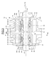
Figure 1 is an axial section of a turbocharger according to a first example of the invention, -
Figure 2 is a view in radial section on II-II ofFigure 1 , -
Figure 3 is an axial section of a turbocharger according to a second example of the invention, and -
Figure 4 is a view in radial section on IV-IV ofFigure 3 . - As illustrated on the
Figure 1 , which illustrates an embodiment of aturbocharger 10 according to an example of the invention, the turbocharger comprises ahousing 12, ashaft 14 extending along alongitudinal axis 14a through a cylindrical bore or opening 16 of the housing, a rollingbearing 18 mounted onto theshaft 14 and disposed into thebore 16, aturbine wheel 20 fixed at one end of theshaft 14 and acompressor wheel 22 fixed at an opposite end of said shaft. Theturbocharger 10 also comprises acap 24 fixed at an axial end of thehousing 12 on the compressor wheel side. In the disclosed embodiment, the axial length of the rolling bearing 18 ranges between 30% and 95% of the axial dimension of thebore 16 of the housing, and more precisely between 70% and 80%. - The rolling
bearing 18 comprises aninner ring 26 and anouter ring 28 between which are housed two rows ofrolling elements 30 and 32, which in this case are balls, twoannular cages rolling elements 30, 32, two annularouter sealing rings inner sealing rings axis 18a of the rolling bearing is coaxial with theaxis 14a of the shaft of the turbocharger. - The inner and
outer rings rings - The
outer ring 28 comprises an outercylindrical surface 28a mounted radially into contact with thebore 16 of the housing and delimited by opposite radiallateral surfaces cap 24 and a radial shoulder of thehousing 12. Theouter ring 28 also comprises abore 28d of cylindrical shape from which are formed toroidal raceways (not referenced) having in cross-section a concave internal profile adapted to therolling elements 30, 32. The raceways are symmetrical with respect to the transverse radial plane passing through the centre of the rolling bearing. - In the disclosed embodiment, the
inner ring 26 is made in two parts which are identical, symmetrical with respect to the transverse radial plane of symmetry of the rolling bearing and mounted axially fixedly one against the other. Theinner ring 26 is here composed of two identical half-rings. Alternatively, the inner ring may be made into one part. Theinner ring 26 has abore 26a of cylindrical shape into which theshaft 14 is mounted. Said bore is delimited by opposite radiallateral surfaces lateral surfaces radial surface 26c axially bears against a radial shoulder of theshaft 14. Theinner ring 26 also comprises an exteriorcylindrical surface 26d onto which first and second toroidal circular raceways (not referenced) are formed. The said raceways have in cross-section a concave internal profile adapted to therolling elements 30 and 32, the said raceways being directed radially outwards. The raceways are symmetrical with respect to the transverse radial plane passing through the centre of the rolling bearing. - The
inner ring 26 also comprises two annular outer grooves (not referenced) formed radially towards the inside from theexterior surface 26d, respectively in the vicinity of theradial surfaces exterior surface 26d. The outer grooves, respectively the inner grooves, are symmetrical with one another relative to the transverse radial plane of symmetry of the rolling bearing. Inside the grooves are fixedly mounted the annular outer andinner sealing rings sealing rings 38 to 44 are disposed radially between the inner andouter rings outer ring 28 and comes into sliding contact with thebore 28d of said ring. Alternatively, the sealing rings may remain at a small distance from said bore. Thesealing rings 38 to 44 are made from metal, advantageously from a thin metal sheet blank. Alternatively, the sealing rings may be made by moulding a synthetic material such as an elastomer. Thesealing rings 38 to 44 are continuous in the circumferential direction. To facilitate their fitting into the grooves of the inner ring, each of the sealing rings may alternatively be open at a point of its circumference. - The sealing
ring 38 is axially situated on the compressor wheel side and the sealingring 40 on the turbine wheel side. The sealingring 38 is located axially between the row ofrolling elements 30 and theradial surfaces ring 40 being mounted axially between the row of rolling elements 32 and theradial surfaces inner sealing rings outer rings outer sealing ring 38, 40 a closed space for each row ofrolling elements 30, 32 and the associatedcages inner sealing rings rings sealing rings rolling elements 30, 32 and theassociated cages - The
turbocharger 10 is further provided with a sealingring 46 mounted radially between theshaft 14 and thecap 24 and axially disposed between thecompressor wheel 22 and the rollingbearing 18, and with twosealing rings shaft 14 and thebore 16 of housing and axially mounted between the rollingbearing 18 and theturbine wheel 20. The sealing rings 46 to 50 are fitted into grooves (not referenced) provided on the exterior surface of theshaft 14 and come into sliding contact with thecap 24 or thehousing 12. The sealing rings 46 to 50 may be made from metal. - The
housing 12 comprises alongitudinal cooling channel 52 extending from aradial end surface 54 of said housing against which thecap 24 is mounted. The coolingchannel 52 extends axially further than theouter ring 28 of the rolling bearing and ends in the vicinity of anradial end surface 56 of the housing located on the turbine wheel side, which is axially opposite to theend surface 54. Aradial bottom 52a of the cooling channel is axially offset outward towards theend surface 56 with regard to theradial surfaces cap 24. A seal (not shown) may be mounted between thehousing 12 and thecap 14. - As shown more clearly on
Figure 2 , the coolingchannel 52 formed within the housing is annular and radially surrounds theouter ring 28 of the rolling bearing on its entire length, and more generally radially surrounds the entire length of said bearing. Thecontinuous cooling channel 52 delimits on thehousing 12 an inneraxial portion 58 comprising thebore 16 inside which is fitted theouter ring 28 of the rolling bearing and an outeraxial portion 60 which is concentric with said inner portion. - The
housing 12 further comprises inlet andoutlet orifices axial portion 60 and diametrically opposed. The inlet andoutlet orifices housing 12 and open into the coolingchannel 52 to communicate with said channel. A cooling fluid (not shown), such as water, can be introduced into thehousing 12 by passing into theinlet orifice 62, said cooling fluid then enters the annular cooling channel and passes out through theoutlet orifice 64. - With the
peripheral cooling channel 52 of the housing extending axially along the entire length of theouter ring 28 of the rolling bearing, the cooling of said rolling bearing is achieved in an effective way. Besides, with the mounting of theouter surface 28a of the outer ring directly into thebore 16 of the housing, the cooling effect of the cooling fluid passing through the coolingchannel 52 is improved since theouter ring 28 is radially located in the vicinity of said channel. - The embodiment shown on
Figures 3 and4 , in which identical parts are given identical references, differs from the previous embodiment in that an annular radial gap orspace 66 exists between theouter surface 28a of the outer ring and thebore 16 of the housing, and in thatradial passages axial portion 58 of the housing. Theannular space 66 is delimited radially by theouter ring 28 and thebore 16 of the housing and axially by the radial shoulder of said housing and thecap 24. In order to seal off thespace 66, seals may be mounted between theradial surfaces 28b of the outer ring and thecap 24 and between theradial surfaces 28c of said ring and thehousing 12. In the disclosed embodiment, theradial passages outlet orifices radial passages channel 52 and pass through the thickness of the inneraxial portion 58 of the housing and open into thebore 16 and theannular space 66. Theannular space 66 communicates with the coolingchannel 52 via theradial passages channel 52 is also supplied into theradial space 66 defined between thehousing 12 and theouter ring 28 of the rolling bearing. The cooling fluid is in direct contact with the entire length of theouter surface 28a of the outer ring, thereby causing an increase of the cooling effect for the rolling bearing. - Otherwise, the cooling fluid disposed into the
radial space 66 may enable to damp the vibrations emitted by the rotation of the turbine andcompressor wheels housing 12 may be limited. Theradial space 66 may act as a cooling and damping space. - It should be noted that the embodiments illustrated and described were given merely by way of non-limitating indicative examples and that modifications and variations are possible within the scope of the invention. In the illustrated embodiments, the cooling channel is annular and radially surrounds the entire axial length of the outer ring of the rolling bearing. Alternatively, it could also be possible to foresee a housing comprising a plurality of longitudinal cooling channel extending axially along the entire length of the outer ring and, spaced apart from each other in the circumferential direction and disposed radially around said outer ring. The invention applies not only to turbocharger comprising an angular contact ball rolling bearing with a double rows of balls but also to turbocharger comprising other types of rolling bearing, for example rolling bearing having four points contact and/or with a single row of balls or with at least three rows of balls.
- Furthermore, the invention applies to rolling bearings comprising a plurality of inner rings and/or a plurality of outer rings. Finally, it has to be made clear that by a turbocharger it is also meant a waste heat recovery turbine, a turbocompound or a compressor.
Claims (11)
- Turbocharger comprising a shaft (14), a housing (12), and a turbine wheel (20) and a compressor wheel (22) mounted onto the shaft, the housing comprising at least a longitudinal cooling channel (52) through which a flow of cooling fluid can pass, characterized in that it further comprises only one rolling bearing (18) disposed between the shaft and the housing and comprising an inner ring (26), an outer ring (28) mounted into a bore (16) of the housing and at least one row of rolling elements (30) disposed between the rings, the cooling channel (52) extending axially along at least the entire length of the outer ring (28).
- Turbocharger according to claim 1, wherein the cooling channel (52) is annular.
- Turbocharger according to claim 1 or 2, wherein the cooling channel (52) is formed within the housing (12).
- Turbocharger according to any of the preceding claims, wherein the cooling channel (52) extends axially from an end surface (54) of the housing.
- Turbocharger according to claim 4, further comprising a cap (24) mounted on the end surface (54) which closes the cooling channel.
- Turbocharger according to claim 4 or 5, wherein the cooling channel (52) extends axially further than the outer ring (28) and ends in the vicinity of an opposite end surface (56) of the housing.
- Turbocharger according to any of the preceding claims, wherein the outer ring (28) is mounted radially into contact with the bore (16) of the housing.
- Turbocharger according to any of the preceding claims 1 to 6, wherein an annular space (66) is defined between an outer surface (28a) of the outer ring and the bore (16) of the housing, the housing comprising passage means (68, 70) communicating with the cooling channel and opening into said space.
- Turbocharger according to any of the preceding claims, wherein the housing comprises inlet and outlet orifices (62, 64) communicating with the cooling channel.
- Turbocharger according to any of the preceding claims, wherein the axial length of the rolling bearing (18) ranges between 30 % and 95 % of the axial dimension of the housing (12), and preferably ranges between 70% and 80%.
- Turbocharger according to any of the preceding claims, wherein the rolling bearing further comprises at least two sealing rings (38, 40) disposed radially between the inner and outer rings and delimiting together with said rings a closed space inside which the row of rolling elements is housed.
Priority Applications (1)
| Application Number | Priority Date | Filing Date | Title |
|---|---|---|---|
| EP11305763.2A EP2535609B2 (en) | 2011-06-17 | 2011-06-17 | Turbocharger, notably for a combustion engine |
Applications Claiming Priority (1)
| Application Number | Priority Date | Filing Date | Title |
|---|---|---|---|
| EP11305763.2A EP2535609B2 (en) | 2011-06-17 | 2011-06-17 | Turbocharger, notably for a combustion engine |
Publications (3)
| Publication Number | Publication Date |
|---|---|
| EP2535609A1 true EP2535609A1 (en) | 2012-12-19 |
| EP2535609B1 EP2535609B1 (en) | 2015-01-21 |
| EP2535609B2 EP2535609B2 (en) | 2021-06-30 |
Family
ID=44510829
Family Applications (1)
| Application Number | Title | Priority Date | Filing Date |
|---|---|---|---|
| EP11305763.2A Active EP2535609B2 (en) | 2011-06-17 | 2011-06-17 | Turbocharger, notably for a combustion engine |
Country Status (1)
| Country | Link |
|---|---|
| EP (1) | EP2535609B2 (en) |
Cited By (1)
| Publication number | Priority date | Publication date | Assignee | Title |
|---|---|---|---|---|
| CN110578562A (en) * | 2019-08-30 | 2019-12-17 | 上海齐耀动力技术有限公司 | cooling structure and connection structure thereof |
Citations (5)
| Publication number | Priority date | Publication date | Assignee | Title |
|---|---|---|---|---|
| US2582916A (en) * | 1947-01-31 | 1952-01-15 | Thompson Prod Inc | Supercharging and fuel heating system for internal-combustion engines |
| US20040200215A1 (en) * | 2001-10-16 | 2004-10-14 | Woollenweber William E. | Bearing system for high-speed rotating machinery |
| JP2007009702A (en) * | 2005-06-28 | 2007-01-18 | Jtekt Corp | Turbocharger bearing device and turbocharger |
| EP2042758A2 (en) | 2007-09-25 | 2009-04-01 | JTEKT Corporation | Rolling bearing device and turbocharger incorporating same |
| DE102009009128A1 (en) * | 2009-02-17 | 2010-08-19 | Bosch Mahle Turbo Systems Gmbh & Co. Kg | Bearing device for shaft of charging device, particularly exhaust gas turbocharger of internal combustion engine, has two angular contact ball bearings, which have one or multiple inner rings, and one or multiple outer rings |
-
2011
- 2011-06-17 EP EP11305763.2A patent/EP2535609B2/en active Active
Patent Citations (5)
| Publication number | Priority date | Publication date | Assignee | Title |
|---|---|---|---|---|
| US2582916A (en) * | 1947-01-31 | 1952-01-15 | Thompson Prod Inc | Supercharging and fuel heating system for internal-combustion engines |
| US20040200215A1 (en) * | 2001-10-16 | 2004-10-14 | Woollenweber William E. | Bearing system for high-speed rotating machinery |
| JP2007009702A (en) * | 2005-06-28 | 2007-01-18 | Jtekt Corp | Turbocharger bearing device and turbocharger |
| EP2042758A2 (en) | 2007-09-25 | 2009-04-01 | JTEKT Corporation | Rolling bearing device and turbocharger incorporating same |
| DE102009009128A1 (en) * | 2009-02-17 | 2010-08-19 | Bosch Mahle Turbo Systems Gmbh & Co. Kg | Bearing device for shaft of charging device, particularly exhaust gas turbocharger of internal combustion engine, has two angular contact ball bearings, which have one or multiple inner rings, and one or multiple outer rings |
Cited By (2)
| Publication number | Priority date | Publication date | Assignee | Title |
|---|---|---|---|---|
| CN110578562A (en) * | 2019-08-30 | 2019-12-17 | 上海齐耀动力技术有限公司 | cooling structure and connection structure thereof |
| CN110578562B (en) * | 2019-08-30 | 2023-08-29 | 上海齐耀动力技术有限公司 | Cooling structure and connection structure thereof |
Also Published As
| Publication number | Publication date |
|---|---|
| EP2535609B2 (en) | 2021-06-30 |
| EP2535609B1 (en) | 2015-01-21 |
Similar Documents
| Publication | Publication Date | Title |
|---|---|---|
| US8845271B2 (en) | Turbocharger bearing system | |
| EP2535526B1 (en) | Turbocharger, notably for a combustion engine. | |
| JP6250360B2 (en) | Turbocharger bearing device and method of manufacturing turbocharger bearing device | |
| US9212700B1 (en) | High efficiency and durable ball bearing system with reduced turbine end heat transfer | |
| EP2565393B1 (en) | Turbocharger bearing comprising an insulating sleeve between the inner bearing ring and the shaft | |
| EP2711573B1 (en) | Bearing device | |
| US8307800B2 (en) | Engine having camshaft lubrication rail | |
| US20180180094A1 (en) | Method For Mounting A Rolling Bearing Unit On The Rotor Of A Turbocharger | |
| US20130224015A1 (en) | Turbocharger, notably for a combustion engine | |
| EP2535607B1 (en) | Turbocharger, notably for a combustion engine | |
| US10167735B2 (en) | Bearing housing oil spray groove | |
| EP2535609B1 (en) | Turbocharger, notably for a combustion engine | |
| JP2009203846A (en) | Ball bearing arrangement for turbocharger | |
| US20140161599A1 (en) | Rolling bearing arrangement of a shaft of an exhaust-gas turbocharger | |
| US20120155793A1 (en) | Bearing arrangement for high-speed shafts of machines | |
| EP3070303B1 (en) | Turbocharger comprising a flinger and insert | |
| CN203979171U (en) | A kind of band lubrication seat subdivision outer spherical surface roller bearing | |
| EP2525108B1 (en) | Turbocharger, notably for a combustion engine | |
| US10697322B2 (en) | Turbocharger, notably for a combustion engine | |
| EP3159561A1 (en) | Bearing device, notably for a turbocharger | |
| WO2015050258A1 (en) | Production method for outer member for wheel bearing device | |
| EP2535608A1 (en) | Rolling bearing, notably for a turbocharger | |
| EP2722494B1 (en) | Turbocharger, notably for a combustion engine, and method for manufacturing such a turbocharger | |
| JP2017002802A (en) | Bearing unit | |
| US20090285518A1 (en) | Axial rolling bearing |
Legal Events
| Date | Code | Title | Description |
|---|---|---|---|
| PUAI | Public reference made under article 153(3) epc to a published international application that has entered the european phase |
Free format text: ORIGINAL CODE: 0009012 |
|
| AK | Designated contracting states |
Kind code of ref document: A1 Designated state(s): AL AT BE BG CH CY CZ DE DK EE ES FI FR GB GR HR HU IE IS IT LI LT LU LV MC MK MT NL NO PL PT RO RS SE SI SK SM TR |
|
| AX | Request for extension of the european patent |
Extension state: BA ME |
|
| 17P | Request for examination filed |
Effective date: 20130408 |
|
| 17Q | First examination report despatched |
Effective date: 20131205 |
|
| REG | Reference to a national code |
Ref country code: DE Ref legal event code: R079 Ref document number: 602011013298 Country of ref document: DE Free format text: PREVIOUS MAIN CLASS: F16C0019180000 Ipc: F16C0027040000 |
|
| GRAP | Despatch of communication of intention to grant a patent |
Free format text: ORIGINAL CODE: EPIDOSNIGR1 |
|
| RIC1 | Information provided on ipc code assigned before grant |
Ipc: F02C 6/12 20060101ALI20140805BHEP Ipc: F16C 27/04 20060101AFI20140805BHEP Ipc: F16C 19/18 20060101ALI20140805BHEP Ipc: F04D 29/059 20060101ALI20140805BHEP Ipc: F04D 25/02 20060101ALI20140805BHEP Ipc: F01D 25/12 20060101ALI20140805BHEP Ipc: F16C 37/00 20060101ALI20140805BHEP Ipc: F01D 25/16 20060101ALI20140805BHEP |
|
| INTG | Intention to grant announced |
Effective date: 20140821 |
|
| GRAS | Grant fee paid |
Free format text: ORIGINAL CODE: EPIDOSNIGR3 |
|
| GRAA | (expected) grant |
Free format text: ORIGINAL CODE: 0009210 |
|
| AK | Designated contracting states |
Kind code of ref document: B1 Designated state(s): AL AT BE BG CH CY CZ DE DK EE ES FI FR GB GR HR HU IE IS IT LI LT LU LV MC MK MT NL NO PL PT RO RS SE SI SK SM TR |
|
| REG | Reference to a national code |
Ref country code: GB Ref legal event code: FG4D |
|
| REG | Reference to a national code |
Ref country code: CH Ref legal event code: EP |
|
| REG | Reference to a national code |
Ref country code: IE Ref legal event code: FG4D |
|
| REG | Reference to a national code |
Ref country code: DE Ref legal event code: R096 Ref document number: 602011013298 Country of ref document: DE Effective date: 20150312 |
|
| REG | Reference to a national code |
Ref country code: AT Ref legal event code: REF Ref document number: 709335 Country of ref document: AT Kind code of ref document: T Effective date: 20150315 |
|
| REG | Reference to a national code |
Ref country code: NL Ref legal event code: VDEP Effective date: 20150121 |
|
| REG | Reference to a national code |
Ref country code: AT Ref legal event code: MK05 Ref document number: 709335 Country of ref document: AT Kind code of ref document: T Effective date: 20150121 |
|
| REG | Reference to a national code |
Ref country code: LT Ref legal event code: MG4D |
|
| REG | Reference to a national code |
Ref country code: FR Ref legal event code: PLFP Year of fee payment: 5 |
|
| PG25 | Lapsed in a contracting state [announced via postgrant information from national office to epo] |
Ref country code: ES Free format text: LAPSE BECAUSE OF FAILURE TO SUBMIT A TRANSLATION OF THE DESCRIPTION OR TO PAY THE FEE WITHIN THE PRESCRIBED TIME-LIMIT Effective date: 20150121 Ref country code: HR Free format text: LAPSE BECAUSE OF FAILURE TO SUBMIT A TRANSLATION OF THE DESCRIPTION OR TO PAY THE FEE WITHIN THE PRESCRIBED TIME-LIMIT Effective date: 20150121 Ref country code: BG Free format text: LAPSE BECAUSE OF FAILURE TO SUBMIT A TRANSLATION OF THE DESCRIPTION OR TO PAY THE FEE WITHIN THE PRESCRIBED TIME-LIMIT Effective date: 20150421 Ref country code: LT Free format text: LAPSE BECAUSE OF FAILURE TO SUBMIT A TRANSLATION OF THE DESCRIPTION OR TO PAY THE FEE WITHIN THE PRESCRIBED TIME-LIMIT Effective date: 20150121 Ref country code: NO Free format text: LAPSE BECAUSE OF FAILURE TO SUBMIT A TRANSLATION OF THE DESCRIPTION OR TO PAY THE FEE WITHIN THE PRESCRIBED TIME-LIMIT Effective date: 20150421 Ref country code: FI Free format text: LAPSE BECAUSE OF FAILURE TO SUBMIT A TRANSLATION OF THE DESCRIPTION OR TO PAY THE FEE WITHIN THE PRESCRIBED TIME-LIMIT Effective date: 20150121 Ref country code: SE Free format text: LAPSE BECAUSE OF FAILURE TO SUBMIT A TRANSLATION OF THE DESCRIPTION OR TO PAY THE FEE WITHIN THE PRESCRIBED TIME-LIMIT Effective date: 20150121 |
|
| PG25 | Lapsed in a contracting state [announced via postgrant information from national office to epo] |
Ref country code: NL Free format text: LAPSE BECAUSE OF FAILURE TO SUBMIT A TRANSLATION OF THE DESCRIPTION OR TO PAY THE FEE WITHIN THE PRESCRIBED TIME-LIMIT Effective date: 20150121 Ref country code: RS Free format text: LAPSE BECAUSE OF FAILURE TO SUBMIT A TRANSLATION OF THE DESCRIPTION OR TO PAY THE FEE WITHIN THE PRESCRIBED TIME-LIMIT Effective date: 20150121 Ref country code: PL Free format text: LAPSE BECAUSE OF FAILURE TO SUBMIT A TRANSLATION OF THE DESCRIPTION OR TO PAY THE FEE WITHIN THE PRESCRIBED TIME-LIMIT Effective date: 20150121 Ref country code: GR Free format text: LAPSE BECAUSE OF FAILURE TO SUBMIT A TRANSLATION OF THE DESCRIPTION OR TO PAY THE FEE WITHIN THE PRESCRIBED TIME-LIMIT Effective date: 20150422 Ref country code: IS Free format text: LAPSE BECAUSE OF FAILURE TO SUBMIT A TRANSLATION OF THE DESCRIPTION OR TO PAY THE FEE WITHIN THE PRESCRIBED TIME-LIMIT Effective date: 20150521 Ref country code: AT Free format text: LAPSE BECAUSE OF FAILURE TO SUBMIT A TRANSLATION OF THE DESCRIPTION OR TO PAY THE FEE WITHIN THE PRESCRIBED TIME-LIMIT Effective date: 20150121 Ref country code: LV Free format text: LAPSE BECAUSE OF FAILURE TO SUBMIT A TRANSLATION OF THE DESCRIPTION OR TO PAY THE FEE WITHIN THE PRESCRIBED TIME-LIMIT Effective date: 20150121 |
|
| REG | Reference to a national code |
Ref country code: DE Ref legal event code: R026 Ref document number: 602011013298 Country of ref document: DE |
|
| PG25 | Lapsed in a contracting state [announced via postgrant information from national office to epo] |
Ref country code: SK Free format text: LAPSE BECAUSE OF FAILURE TO SUBMIT A TRANSLATION OF THE DESCRIPTION OR TO PAY THE FEE WITHIN THE PRESCRIBED TIME-LIMIT Effective date: 20150121 Ref country code: RO Free format text: LAPSE BECAUSE OF FAILURE TO SUBMIT A TRANSLATION OF THE DESCRIPTION OR TO PAY THE FEE WITHIN THE PRESCRIBED TIME-LIMIT Effective date: 20150121 Ref country code: EE Free format text: LAPSE BECAUSE OF FAILURE TO SUBMIT A TRANSLATION OF THE DESCRIPTION OR TO PAY THE FEE WITHIN THE PRESCRIBED TIME-LIMIT Effective date: 20150121 Ref country code: CZ Free format text: LAPSE BECAUSE OF FAILURE TO SUBMIT A TRANSLATION OF THE DESCRIPTION OR TO PAY THE FEE WITHIN THE PRESCRIBED TIME-LIMIT Effective date: 20150121 Ref country code: DK Free format text: LAPSE BECAUSE OF FAILURE TO SUBMIT A TRANSLATION OF THE DESCRIPTION OR TO PAY THE FEE WITHIN THE PRESCRIBED TIME-LIMIT Effective date: 20150121 |
|
| PLBI | Opposition filed |
Free format text: ORIGINAL CODE: 0009260 |
|
| PLAX | Notice of opposition and request to file observation + time limit sent |
Free format text: ORIGINAL CODE: EPIDOSNOBS2 |
|
| 26 | Opposition filed |
Opponent name: BORGWARNER, INC. Effective date: 20151019 |
|
| PG25 | Lapsed in a contracting state [announced via postgrant information from national office to epo] |
Ref country code: IT Free format text: LAPSE BECAUSE OF FAILURE TO SUBMIT A TRANSLATION OF THE DESCRIPTION OR TO PAY THE FEE WITHIN THE PRESCRIBED TIME-LIMIT Effective date: 20150121 |
|
| PG25 | Lapsed in a contracting state [announced via postgrant information from national office to epo] |
Ref country code: MC Free format text: LAPSE BECAUSE OF FAILURE TO SUBMIT A TRANSLATION OF THE DESCRIPTION OR TO PAY THE FEE WITHIN THE PRESCRIBED TIME-LIMIT Effective date: 20150121 |
|
| REG | Reference to a national code |
Ref country code: CH Ref legal event code: PL |
|
| GBPC | Gb: european patent ceased through non-payment of renewal fee |
Effective date: 20150617 |
|
| PG25 | Lapsed in a contracting state [announced via postgrant information from national office to epo] |
Ref country code: SI Free format text: LAPSE BECAUSE OF FAILURE TO SUBMIT A TRANSLATION OF THE DESCRIPTION OR TO PAY THE FEE WITHIN THE PRESCRIBED TIME-LIMIT Effective date: 20150121 Ref country code: LU Free format text: LAPSE BECAUSE OF FAILURE TO SUBMIT A TRANSLATION OF THE DESCRIPTION OR TO PAY THE FEE WITHIN THE PRESCRIBED TIME-LIMIT Effective date: 20150617 |
|
| REG | Reference to a national code |
Ref country code: IE Ref legal event code: MM4A |
|
| PLBB | Reply of patent proprietor to notice(s) of opposition received |
Free format text: ORIGINAL CODE: EPIDOSNOBS3 |
|
| PG25 | Lapsed in a contracting state [announced via postgrant information from national office to epo] |
Ref country code: LI Free format text: LAPSE BECAUSE OF NON-PAYMENT OF DUE FEES Effective date: 20150630 Ref country code: GB Free format text: LAPSE BECAUSE OF NON-PAYMENT OF DUE FEES Effective date: 20150617 Ref country code: IE Free format text: LAPSE BECAUSE OF NON-PAYMENT OF DUE FEES Effective date: 20150617 Ref country code: CH Free format text: LAPSE BECAUSE OF NON-PAYMENT OF DUE FEES Effective date: 20150630 |
|
| PG25 | Lapsed in a contracting state [announced via postgrant information from national office to epo] |
Ref country code: BE Free format text: LAPSE BECAUSE OF FAILURE TO SUBMIT A TRANSLATION OF THE DESCRIPTION OR TO PAY THE FEE WITHIN THE PRESCRIBED TIME-LIMIT Effective date: 20150121 |
|
| REG | Reference to a national code |
Ref country code: FR Ref legal event code: PLFP Year of fee payment: 6 |
|
| PG25 | Lapsed in a contracting state [announced via postgrant information from national office to epo] |
Ref country code: MT Free format text: LAPSE BECAUSE OF FAILURE TO SUBMIT A TRANSLATION OF THE DESCRIPTION OR TO PAY THE FEE WITHIN THE PRESCRIBED TIME-LIMIT Effective date: 20150121 |
|
| PG25 | Lapsed in a contracting state [announced via postgrant information from national office to epo] |
Ref country code: SM Free format text: LAPSE BECAUSE OF FAILURE TO SUBMIT A TRANSLATION OF THE DESCRIPTION OR TO PAY THE FEE WITHIN THE PRESCRIBED TIME-LIMIT Effective date: 20150121 Ref country code: HU Free format text: LAPSE BECAUSE OF FAILURE TO SUBMIT A TRANSLATION OF THE DESCRIPTION OR TO PAY THE FEE WITHIN THE PRESCRIBED TIME-LIMIT; INVALID AB INITIO Effective date: 20110617 |
|
| REG | Reference to a national code |
Ref country code: FR Ref legal event code: PLFP Year of fee payment: 7 |
|
| PG25 | Lapsed in a contracting state [announced via postgrant information from national office to epo] |
Ref country code: CY Free format text: LAPSE BECAUSE OF FAILURE TO SUBMIT A TRANSLATION OF THE DESCRIPTION OR TO PAY THE FEE WITHIN THE PRESCRIBED TIME-LIMIT Effective date: 20150121 |
|
| PLAB | Opposition data, opponent's data or that of the opponent's representative modified |
Free format text: ORIGINAL CODE: 0009299OPPO |
|
| R26 | Opposition filed (corrected) |
Opponent name: BORGWARNER, INC. Effective date: 20151019 |
|
| PG25 | Lapsed in a contracting state [announced via postgrant information from national office to epo] |
Ref country code: TR Free format text: LAPSE BECAUSE OF FAILURE TO SUBMIT A TRANSLATION OF THE DESCRIPTION OR TO PAY THE FEE WITHIN THE PRESCRIBED TIME-LIMIT Effective date: 20150121 |
|
| APBM | Appeal reference recorded |
Free format text: ORIGINAL CODE: EPIDOSNREFNO |
|
| APBP | Date of receipt of notice of appeal recorded |
Free format text: ORIGINAL CODE: EPIDOSNNOA2O |
|
| APAH | Appeal reference modified |
Free format text: ORIGINAL CODE: EPIDOSCREFNO |
|
| APAW | Appeal reference deleted |
Free format text: ORIGINAL CODE: EPIDOSDREFNO |
|
| APBM | Appeal reference recorded |
Free format text: ORIGINAL CODE: EPIDOSNREFNO |
|
| APBP | Date of receipt of notice of appeal recorded |
Free format text: ORIGINAL CODE: EPIDOSNNOA2O |
|
| APBQ | Date of receipt of statement of grounds of appeal recorded |
Free format text: ORIGINAL CODE: EPIDOSNNOA3O |
|
| APBQ | Date of receipt of statement of grounds of appeal recorded |
Free format text: ORIGINAL CODE: EPIDOSNNOA3O |
|
| PG25 | Lapsed in a contracting state [announced via postgrant information from national office to epo] |
Ref country code: PT Free format text: LAPSE BECAUSE OF FAILURE TO SUBMIT A TRANSLATION OF THE DESCRIPTION OR TO PAY THE FEE WITHIN THE PRESCRIBED TIME-LIMIT Effective date: 20150121 Ref country code: MK Free format text: LAPSE BECAUSE OF FAILURE TO SUBMIT A TRANSLATION OF THE DESCRIPTION OR TO PAY THE FEE WITHIN THE PRESCRIBED TIME-LIMIT Effective date: 20150121 |
|
| REG | Reference to a national code |
Ref country code: FR Ref legal event code: PLFP Year of fee payment: 8 |
|
| PG25 | Lapsed in a contracting state [announced via postgrant information from national office to epo] |
Ref country code: AL Free format text: LAPSE BECAUSE OF FAILURE TO SUBMIT A TRANSLATION OF THE DESCRIPTION OR TO PAY THE FEE WITHIN THE PRESCRIBED TIME-LIMIT Effective date: 20150121 |
|
| APBU | Appeal procedure closed |
Free format text: ORIGINAL CODE: EPIDOSNNOA9O |
|
| RIN2 | Information on inventor provided after grant (corrected) |
Inventor name: VIAULT, SAMUEL Inventor name: WENSING, JEOREN Inventor name: BERRUET, NICOLAS Inventor name: CORBETT, RICHARD |
|
| PUAH | Patent maintained in amended form |
Free format text: ORIGINAL CODE: 0009272 |
|
| STAA | Information on the status of an ep patent application or granted ep patent |
Free format text: STATUS: PATENT MAINTAINED AS AMENDED |
|
| 27A | Patent maintained in amended form |
Effective date: 20210630 |
|
| AK | Designated contracting states |
Kind code of ref document: B2 Designated state(s): AL AT BE BG CH CY CZ DE DK EE ES FI FR GB GR HR HU IE IS IT LI LT LU LV MC MK MT NL NO PL PT RO RS SE SI SK SM TR |
|
| REG | Reference to a national code |
Ref country code: DE Ref legal event code: R102 Ref document number: 602011013298 Country of ref document: DE |
|
| P01 | Opt-out of the competence of the unified patent court (upc) registered |
Effective date: 20230513 |
|
| PGFP | Annual fee paid to national office [announced via postgrant information from national office to epo] |
Ref country code: DE Payment date: 20250626 Year of fee payment: 15 |
|
| PGFP | Annual fee paid to national office [announced via postgrant information from national office to epo] |
Ref country code: FR Payment date: 20250624 Year of fee payment: 15 |
|
| REG | Reference to a national code |
Ref country code: DE Ref legal event code: R082 Ref document number: 602011013298 Country of ref document: DE Representative=s name: SCHONECKE, MITJA, DIPL.-PHYS. DR. RER. NAT., DE Ref country code: DE Ref legal event code: R082 Ref document number: 602011013298 Country of ref document: DE Representative=s name: SCHONECKE, MITJA, DR., DE |
|
| REG | Reference to a national code |
Ref country code: DE Ref legal event code: R082 Ref document number: 602011013298 Country of ref document: DE Representative=s name: SCHONECKE, MITJA, DR., DE |