EP2535592B1 - Assembly with Compressor Wheel and Turbine wheel - Google Patents
Assembly with Compressor Wheel and Turbine wheel Download PDFInfo
- Publication number
- EP2535592B1 EP2535592B1 EP12169668.6A EP12169668A EP2535592B1 EP 2535592 B1 EP2535592 B1 EP 2535592B1 EP 12169668 A EP12169668 A EP 12169668A EP 2535592 B1 EP2535592 B1 EP 2535592B1
- Authority
- EP
- European Patent Office
- Prior art keywords
- nose piece
- compressor wheel
- assembly
- boreless
- wheel
- Prior art date
- Legal status (The legal status is an assumption and is not a legal conclusion. Google has not performed a legal analysis and makes no representation as to the accuracy of the status listed.)
- Active
Links
Images




Classifications
-
- F—MECHANICAL ENGINEERING; LIGHTING; HEATING; WEAPONS; BLASTING
- F04—POSITIVE - DISPLACEMENT MACHINES FOR LIQUIDS; PUMPS FOR LIQUIDS OR ELASTIC FLUIDS
- F04D—NON-POSITIVE-DISPLACEMENT PUMPS
- F04D29/00—Details, component parts, or accessories
- F04D29/26—Rotors specially for elastic fluids
- F04D29/266—Rotors specially for elastic fluids mounting compressor rotors on shafts
-
- F—MECHANICAL ENGINEERING; LIGHTING; HEATING; WEAPONS; BLASTING
- F04—POSITIVE - DISPLACEMENT MACHINES FOR LIQUIDS; PUMPS FOR LIQUIDS OR ELASTIC FLUIDS
- F04D—NON-POSITIVE-DISPLACEMENT PUMPS
- F04D17/00—Radial-flow pumps, e.g. centrifugal pumps; Helico-centrifugal pumps
- F04D17/08—Centrifugal pumps
- F04D17/10—Centrifugal pumps for compressing or evacuating
- F04D17/105—Centrifugal pumps for compressing or evacuating with double suction
-
- F—MECHANICAL ENGINEERING; LIGHTING; HEATING; WEAPONS; BLASTING
- F04—POSITIVE - DISPLACEMENT MACHINES FOR LIQUIDS; PUMPS FOR LIQUIDS OR ELASTIC FLUIDS
- F04D—NON-POSITIVE-DISPLACEMENT PUMPS
- F04D29/00—Details, component parts, or accessories
- F04D29/66—Combating cavitation, whirls, noise, vibration or the like; Balancing
- F04D29/661—Combating cavitation, whirls, noise, vibration or the like; Balancing especially adapted for elastic fluid pumps
- F04D29/662—Balancing of rotors
-
- Y—GENERAL TAGGING OF NEW TECHNOLOGICAL DEVELOPMENTS; GENERAL TAGGING OF CROSS-SECTIONAL TECHNOLOGIES SPANNING OVER SEVERAL SECTIONS OF THE IPC; TECHNICAL SUBJECTS COVERED BY FORMER USPC CROSS-REFERENCE ART COLLECTIONS [XRACs] AND DIGESTS
- Y10—TECHNICAL SUBJECTS COVERED BY FORMER USPC
- Y10T—TECHNICAL SUBJECTS COVERED BY FORMER US CLASSIFICATION
- Y10T29/00—Metal working
- Y10T29/49—Method of mechanical manufacture
- Y10T29/49316—Impeller making
- Y10T29/4932—Turbomachine making
Definitions
- Subject matter disclosed herein relates generally to turbomachinery for internal combustion engines and, in particular, to compressor wheels configured for receipt of a nose piece.
- Exhaust driven turbochargers include a rotating group that includes a turbine wheel and a compressor wheel that are connected to one another by a shaft.
- the shaft is typically rotatably supported within a center housing by one or more bearings (e.g., oil lubricated, air bearings, ball bearings, magnetic bearings, etc.).
- bearings e.g., oil lubricated, air bearings, ball bearings, magnetic bearings, etc.
- exhaust from an internal combustion engine drives a turbocharger's turbine wheel, which, in turn, drives the compressor wheel to boost charge air to the internal combustion engine.
- a turbocharger's rotating group must operate through a wide range of speeds. Depending on the size of the turbocharger, the maximum speed reached may be in excess of 200,000 rpm. Because of the wide operating range and the inherent design of the rotating group, most turbocharger rotating groups fit the definition of a "flexible rotor". Flexible rotors require a unique balancing process to assure that residual unbalance in all balance planes are controlled and results verified with a test of the unbalance response throughout the operating range. A well balanced turbocharger rotating group is essential for proper rotordynamic performance. Efforts to achieve low levels of unbalance help to assure shaft stability and minimize rotor deflection which in turn acts to reduce bearing loads. Reduced bearing loads result in improved durability and reduced noise (e.g., as resulting from transmitted vibration).
- turbocharger rotating group balancing includes component and assembly balancing. Individual components such as the compressor and turbine wheel assembly are typically balanced using a low rotational speed process while assembly (e.g., the completely assembled rotating group) are typically balanced using a high speed balancing process. Normally, the balance quality of the assembly is improved with a correction made on the compressor end of the rotating group alone.
- Compressor wheel designs may be of two main types, those with a through bore and those without a through bore, which are referred to as "boreless".
- the assembly process includes inserting a shaft in through the bore of the wheel and fixing the wheel to the shaft with a lock nut.
- the assembly is then installed in a high speed balancing machine for measurement and correction.
- the high speed balancer provides a means to operate the rotating group at the high speeds needed to provide adequate measurement and correction. Unbalance can be measured using instrumentation such as an accelerometer to provide an indication of unbalance in terms of vibration, or g's.
- the information provided by the high speed balancer can guide an operator, for example, by indicating where to remove material from the lock nut (e.g., phase angle of unbalance) to improve the balance.
- a high speed balancer may rely on a magnetic field sensor or an optical sensor.
- the lock nut is magnetized (i.e., made of a magentizable material) whereas, for an optical sensor, one or more markings made on the lock nut or wheel may suffice.
- the magnetic method is generally preferred as being more accurate and reliable than the optical method.
- US 2,602,683 discloses a rotor and separable shaft assembly for a turbomachine.
- EP 1 273 757 A1 discloses an assembly comprising a boreless compressor wheel that comprises a receptacle configured for receipt of a rotatable shaft and a turbine wheel that comprises a shaft having an end received by the receptacle of the boreless compressor wheel.
- EP 1 803 941 A1 discloses a turbocharger with a compressor impeller.
- GB 2 410 992 A discloses a compressor with shaft stub and engagement features to align compressor with shaft.
- DE 4 444 082 A discloses a turbo charger with a compressor rotor fixed to the stub end of a turbine shaft.
- EP 0 138 516 A1 discloses a centrifugal compressor apparatus.
- components include nose pieces and boreless compressor wheels configured to receive such nose pieces.
- an assembly includes inter alia a nose piece and a boreless compressor wheel that includes a nose end configured for receipt of the nose piece and a receptacle at a base end configured for receipt of a rotatable shaft.
- a shaft may be a turbocharger shaft or other rotatable shaft (e.g., driven by a belt, a chain, electric motor, etc.).
- a boreless compressor wheel with a nose piece or balanced using a nose piece is used for turbocharger, supercharger or other applications.
- a nose piece facilitates balancing.
- a nose piece may be made of a magnetizable material that allows for measuring unbalance via a magnetic field sensor. Material is removed from a nose piece to improve balance (e.g., based on measured unbalance). Accordingly, a nose piece facilitates measurement of unbalance, balancing or measurement of unbalance and balancing.
- a boreless compressor wheel can be one in which there is a single compressor wheel or one that includes two compressor impellers or faces.
- a wheel with two compressor impellers e.g., mounted in a back to back fashion
- each impeller face may be directed to a dedicated diffuser section, a dedicated volute, a shared diffuser section, a shared volute, etc.
- a nose piece includes a stem and a nose end of a boreless compressor wheel includes a receptacle configured to receive the stem.
- a nose piece can include an opening and a nose end of a boreless compressor wheel can include a stem configured for insertion into the opening of the nose piece.
- a nose piece may be attached to a boreless compressor wheel by any of a variety of mechanisms.
- features of a boreless compressor wheel and a nose piece may be configured for press fitting the nose piece on to the boreless compressor wheel
- a boreless compressor wheel and a nose piece may include cooperative threads for threading the nose piece on to the boreless compressor wheel
- a nose piece may be configured to shrink fit on to a boreless compressor wheel (e.g., heated to expand and then cooled to shrink fit).
- a nose piece may include an internal drive, an external drive or both an internal drive and an external drive, for example, where such drives are configured to cooperate with a tool or tools.
- an assembly includes inter alia a boreless compressor wheel that includes a nose piece with one or more balance cuts (e.g., to provide for balance of the assembly) and a receptacle configured for receipt of a shaft; and a turbine wheel that includes a shaft having an end received by the receptacle of the boreless compressor wheel.
- a boreless compressor wheel that includes a nose piece with one or more balance cuts (e.g., to provide for balance of the assembly) and a receptacle configured for receipt of a shaft; and a turbine wheel that includes a shaft having an end received by the receptacle of the boreless compressor wheel.
- Such an assembly may include a nose piece made of a magnetizable material.
- an exemplary method can include fitting a nose piece to a boreless compressor wheel, measuring unbalance, and, based in part on the measuring, removing material from the nose piece.
- An exemplary method may include removing a nose piece from a boreless compressor wheel and fitting another nose piece to the boreless compressor wheel.
- various techniques may be used, for example, consider a technique that includes rotating a boreless compressor wheel and a nose piece and measuring magnetic field properties associated with the nose piece.
- an exemplary method can include assembling a turbocharger that includes a boreless compressor wheel and a nose piece having at least some material removed.
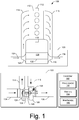
- a conventional system 100 includes an internal combustion engine 110 and a turbocharger 120.
- the internal combustion engine 110 includes an engine block 118 housing one or more combustion chambers that operatively drive a shaft 112 (e.g., via pistons).
- an intake port 114 provides a flow path for air to the engine block 118 while an exhaust port 116 provides a flow path for exhaust from the engine block 118.
- the turbocharger 120 acts to extract energy from the exhaust and to provide energy to intake air, which may be combined with fuel to form combustion gas.
- the turbocharger 120 includes an air inlet 134, a shaft 122, a compressor 124, a turbine 126, a housing 128 and an exhaust outlet 136.
- the housing 128 may be referred to as a center housing as it is disposed between the compressor 124 and the turbine 126.
- the shaft 122 may be a shaft assembly that includes a variety of components.
- a wastegate valve (or simply wastegate) 135 is positioned proximate to the inlet of the turbine 126. The wastegate valve 135 can be controlled to allow exhaust from the exhaust port 116 to bypass the turbine 126.
- a controller 190 is shown as including one or more processors 192, memory 194 and one or more interfaces 196.
- a controller may include circuitry such as circuitry of an engine control unit.
- various methods or techniques may optionally be implemented in conjunction with a controller, for example, through control logic.
- Control logic may depend on one or more engine operating conditions (e.g., turbo rpm, engine rpm, temperature, load, lubricant, cooling, etc.).
- sensors may transmit information to the controller 190 via the one or more interfaces 196.
- Control logic may rely on such information and, in turn, the controller 190 may output control signals to control engine operation.
- the controller 190 may be configured to control lubricant flow, temperature, a variable geometry assembly (e.g., variable geometry compressor or turbine), a wastegate, an electric motor, or one or more other components associated with an engine, a turbocharger (or turbochargers), etc. More generally, as described herein, a controller may be configured for use in another process such as a balancing process.
- a variable geometry assembly e.g., variable geometry compressor or turbine
- a wastegate e.g., a turbogate, or one or more other components associated with an engine, a turbocharger (or turbochargers), etc. More generally, as described herein, a controller may be configured for use in another process such as a balancing process.
- Fig. 2 shows examples of two conventional assemblies 200 and 250 where each of the assemblies includes a compressor wheel 220 or 270 having a through bore 222 or 272 and a lock nut 210 or 260 fixed to a shaft 201 or 251 that extends through the through bore 222 or 272.
- the compressor wheel 270 includes two impeller faces 275 and 277 while the compressor wheel 220 includes only a single impeller face.
- each of the shafts 201 and 251 extends from a respective turbine wheel 240 and 290. Disposed axially along each of the shafts 201 and 251 are respective thrust collars 213 and 263 and respective bearings 215 and 265.
- the shaft 201 includes a compressor wheel portion 202, a thrust collar portion 203, a compressor journal bearing portion 204, a bearing portion 205, and a turbine journal bearing portion 206.
- the shaft 251 also includes a compressor wheel portion 252, a thrust collar portion 253, a compressor journal bearing portion 254, a bearing portion 255, and a turbine journal bearing portion 256.
- Various axial dimensions are shown for the bearings 215 and 265 (z B ), the thrust collars 213 and 263 (z B ), the compressor wheels 220 and 270 (z C ), and the lock nuts 210 and 260 (z N ).
- the compressor wheel 220 includes a nose end 224 that abuts the lock nut 210 and a base end 226 that abuts the thrust collar 213.
- the compressor wheel 220 has a minimum radius r C-Min at its nose end 224 and has a maximum wheel radius r C-Max at an edge 228 that coincides with a so-called z-plane.
- the compressor wheel 270 includes a nose end 274 that abuts the lock nut 260 and a base end 276 that abuts the thrust collar 263.
- the compressor wheel 270 has a minimum radius r C-Min at its nose end 274 and has a maximum wheel radius r C-Max at an edge 278 that coincides with a so-called z-plane.
- a lock nut is typically made of steel and suitable measuring unbalance through magnetic field sensing.
- one or more cuts may be made in a lock nut according to information provided by a balancing machine (e.g., a VSR).
- a balancing machine e.g., a VSR
- Fig. 3 shows examples of two conventional assemblies 300 and 350 where each of the assemblies includes a boreless compressor wheel 320 or 370 having a receptacle 322 or 372 that receives a shaft 301 or 351.
- the compressor wheel 370 includes two impeller faces 375 and 377 while the compressor wheel 320 includes only a single impeller face.
- each of the shafts 301 and 351 extends from a respective turbine wheel 340 and 390. Disposed axially along each of the shafts 301 and 351 are respective thrust collars 313 and 363 and respective bearings 315 and 365.
- the shaft 301 includes a compressor wheel portion 302, a thrust collar portion 303, a compressor journal bearing portion 304, a bearing portion 305, and a turbine journal bearing portion 306.
- the shaft 351 also includes a compressor wheel portion 352, a thrust collar portion 353, a compressor journal bearing portion 354, a bearing portion 355, and a turbine journal bearing portion 356.
- the compressor wheel 320 includes a nose end 324 and a base end 326 that abuts the thrust collar 313.
- the compressor wheel 320 has a maximum wheel radius r C-Max at an edge 328 that coincides with a so-called z-plane.
- the compressor wheel 370 includes a nose end 374 and a base end 376 that abuts the thrust collar 363.
- the compressor wheel 370 has a maximum wheel radius r C-Max at an edge 378 that coincides with a so-called z-plane.
- one or more markings are typically made on a boreless compressor wheel followed by measuring unbalance through optical sensing of such marking or markings.
- one or more cuts are made in a nose end of a boreless compressor wheel according to information provided by a balancing machine (e.g., a VSR).
- a balancing machine e.g., a VSR
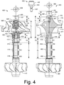
- Fig. 4 shows examples of assemblies 400 and 450 where each of the assemblies includes a boreless compressor wheel 420 and 470 where each of the boreless compressor wheels 420 and 470 has a receptacle 421 and 471 in receipt of a respective nose piece 430 and 480 and another receptacle 422 and 472 in receipt of an end portion 402 and 452 of a respective shaft 401 and 451.
- the compressor wheel 470 includes two impeller faces 475 and 477 while the compressor wheel 420 includes only a single impeller face.
- each of the shafts 401 and 451 extends from a respective turbine wheel 440 and 490. Disposed axially along each of the shafts 401 and 451 are respective thrust collars 413 and 463 and respective bearings 415 and 465.
- the shaft 401 includes the end portion 402, a thrust collar portion 403, a compressor journal bearing portion 404, a bearing portion 405, and a turbine journal bearing portion 406.
- the shaft 451 also includes an end portion 452, a thrust collar portion 453, a compressor journal bearing portion 454, a bearing portion 455, and a turbine journal bearing portion 456.
- the compressor wheel 420 includes a nose end 424 that abuts the nose piece 430 and a base end 426 that abuts the thrust collar 413.
- the compressor wheel 420 has a minimum wheel radius r C-Min at the nose end 424 and a maximum wheel radius r C-Max at an edge 428 that coincides with a so-called z-plane.
- the compressor wheel 470 includes a nose end 474 that abuts the nose piece 480 and a base end 476 that abuts the thrust collar 463.
- the compressor wheel 470 has a minimum wheel radius r C-Min at the nose end 474 and a maximum wheel radius r C-Max at an edge 478 that coincides with a so-called z-plane.
- Fig. 4 also shows top views of the nose pieces 430 and 480, which illustrate optional internal drives 435 and 485.
- a perspective view shows the nose piece 430 as including an optional external drive disposed between a head portion 432 and the stem 431.
- the nose piece 480 is also shown as including an optional external drive 483 disposed between a head portion 482 and a stem portion 481.
- Such drives can allow for rotation of at least a nose piece, for example, to attach a nose piece to a boreless compressor wheel or, for example, to rotate a nose piece and boreless compressor wheel as an assembly.
- a nose piece allows for measurement of unbalance, balancing or measurement of unbalance and balancing.
- one or more cuts are may made in a nose piece attached to a boreless compressor wheel according to information provided by a balancing machine (e.g., a VSR).
- a balancing machine e.g., a VSR
- a nose piece may be made of steel, aluminum or another material.
- Fig. 5 shows various views of the nose pieces 430 and 480 and the boreless compressor wheel receptacles 421 and 471 of the examples of Fig. 4 .
- the nose pieces 430 and 480 may include common features.
- the nose pieces 430 and 480 may include one or more pilot surfaces along their respective stems 431 and 481.
- a pilot surface is typically disposed at a radius extending over an axial length.
- the nose pieces 430 and 480 include two pilot surfaces P 1 and P 2 disposed at respective radii r P1 and r P2 and extending over respective axial lengths Z P1 and Z P2 .
- Fig. 5 shows various views of the nose pieces 430 and 480 and the boreless compressor wheel receptacles 421 and 471 of the examples of Fig. 4 .
- the nose pieces 430 and 480 may include common features.
- the nose pieces 430 and 480 may include one or more pilot surfaces along their respective stems 431 and 481.
- a pilot surface is typically
- a neck is disposed between the pilot surfaces P1 and P2, which has a radius r nk and an axial length z nk .
- Other dimensions of the nose pieces 430 and 480 shown in Fig. 5 include an axial head length (z h ) and a head radius (r h ), an axial external drive length (z ed ) and an external drive radius (r ed ), and an axial internal drive length (z id ) and an internal drive radius (r id ).
- a nose piece has a head portion of sufficient mass such that removal of some of the mass (e.g., via cutting or other technique) can improve balance of nose piece and boreless wheel assembly.
- the receptacle 421 of the boreless compressor wheel 420 and the receptacle 471 of the boreless compressor wheel 470 may include a surface with an axial length z CP1 and a radius r CP1 and a surface with an axial length z CP2 and a radius r CP2 where such surfaces cooperate with a pilot surface of a portion of a nose piece such as the pilot surfaces P 1 and P 2 of the nose pieces 430 and 480.
- the receptacles 421 and 471 do not extend axially to the z-plane.
- the receptacles 422 and 472 do not extend axially to the z-plane.
- the boreless wheel 420 or the boreless wheel 470 may optionally be characterized as including two axially aligned and opposing receptacles that do not extend to a z-plane of a wheel.
- such a wheel has a solid portion (i.e., boreless portion) located axially between the two opposing receptacles.
- a receptacle may be shaped at a distal end (e.g., closed end) to reduce stress.
- a portion of a nose piece may include threads while a portion of a boreless compressor wheel includes cooperating threads. Accordingly, a nose piece may be rotated with respect to a boreless compressor wheel to secure the nose piece to the wheel.
- Other mechanisms for attachment may include bayonet, press fit via appropriate clearances, etc.
- a pilot surface or other feature may help align a nose piece along a rotational axis of a boreless compressor wheel.
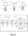
- Fig. 6 shows some examples of nose pieces 610, 620 and 630 and examples of cuts for removal of material from a nose piece 650.
- the nose piece 610 includes a threaded stem 611 and an external drive 613.
- a tool such as a wrench may engage the external drive 613 to rotate the nose piece 610 with respect to a boreless compressor wheel to thereby secure the nose piece 610 to the boreless compressor wheel.
- the external drive 613 may allow for rotation of the nose piece 610 and the boreless compress wheel as a unit.
- the nose piece 620 includes a threaded stem 621 and an internal drive 625.
- a tool such as a hex wrench may engage the internal drive 625 to rotate the nose piece 620 with respect to a boreless compressor wheel to thereby secure the nose piece 620 to the boreless compressor wheel.
- the internal drive 625 may allow for rotation of the nose piece 620 and the boreless compress wheel as a unit.
- the nose piece 630 includes a threaded stem 631 without any pilot surfaces and an external drive 633.
- a tool such as a wrench may engage the external drive 633 to rotate the nose piece 630 with respect to a boreless compressor wheel to thereby secure the nose piece 630 to the boreless compressor wheel.
- the external drive 633 may allow for rotation of the nose piece 630 and the boreless compress wheel as a unit.
- a drive or drives may be suitable used in conjunction with an appropriate tool or tools to remove the nose piece.
- the drives 613, 625 and 633 of the nose pieces 610, 620 and 630 may be used for installation and removal. While the examples of Fig. 6 show threads, as described herein, other mechanisms may be used to secure a nose piece to a boreless compressor wheel.
- Fig. 6 also shows various balance cuts 650 with respect to a nose piece 670, a nose piece 680 and a nose piece 690, which are to be fitted to a boreless compressor wheel 660.
- the cuts may be made from an end of a nose piece and extend axially downward. In such a manner, material is removed to improve balance.
- phase information may guide an operator as to angle of a cut. While all of the cuts 650 are shown as being aligned (e.g., centered at 90 degrees), a cut may be aligned at any angle about a nose piece and made in any manner or shape.
- Fig. 7 shows an example of a nose piece 710 and a boreless compressor wheel 720 along with balancing equipment 795 and 797 and a plot 798 of measured unbalance versus rotational speed.
- the nose piece includes a stem 711 and a head 712 while the boreless compressor wheel 720 includes a receptacle 722 with an axial length z CP and a radius r CP .
- the nose piece 710 may be fitted to the boreless compressor wheel 720 by inserting the stem 711 into the receptacle 722.
- a nose piece may be attached to a boreless compressor wheel via any of a variety of mechanisms, such as, for example, threads, press fit, etc.
- the nose piece 710 is made of a magnetizable material such as steel.
- the nose piece 710 may be magnetized, for example, magnetizing may occur by passing a magnet closely by the nose piece 710.
- the nose piece 710 as affixed to the boreless compressor wheel 720 may be placed in a shroud 797 and rotated such that a magnetic field sensor 795 can measure unbalance.
- such information may be plotted as shown in the plot 798 as g-level versus rpm.
- the plot 798 shows a solid line that represents unbalance prior to removal of material from the nose piece 710, the boreless compressor wheel 720 or from the nose piece 710 and the boreless compressor wheel 720 as well as a dashed line that represents a reduced g-level (or vibration unbalance) after removal of material.
- a nose piece made from or including a magnetizable material can allow for magnetic field-based measurement of unbalance of a boreless compressor wheel made of a non-magnetizable material. Further, such a nose piece can allow for alteration of a center of mass of an assembly to improve balance (e.g., by removal of material via a cut or other technique).
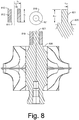
- Fig. 8 shows an example of a nose piece 810 and a boreless compressor wheel 820.
- a nose piece may be for purposes of sensing unbalance using a magnetic field sensor, for purposes of material removal to improve balance or a combination of both sensing and material removal to improve balance.
- the nose piece 810 includes an opening 811 with a radius r i while the boreless compressor wheel 820 includes a stem portion 821 with a radius r CP .
- Other dimensions shown in Fig. 8 include a nose piece outer radius (r h ), a nose piece axial length (z h ) and a stem axial length (z CP ).
- the nose piece 810 is received by the stem 821 of the boreless compressor wheel 820. Clearances between the opening 811 and the stem 821 may provide for a secure press fit. As another example, a nose piece may be provided that responds to heating or other processing to shrink fit securely onto the stem 821. As described herein, such a fit may be relatively permanent or allow for reversal if removal and replacement of the nose piece is desired.
- the nose piece 810 may be made of or include a magnetizable material while the boreless compressor wheel 820 may be made of a non-magnetizable material.
- material is removed from the nose piece 810, from the boreless compressor wheel 820 or from both the nose piece 810 and the boreless compressor wheel 820.
- the thickness of the nose piece 810 must be sufficient to receive a cut for purposes of improving balance of a nose piece and boreless wheel assembly.
- balance cuts 650 extend axially downward. With respect to the nose piece 810, cuts may extend axially downward a distance less than the axial length (z h ) of the nose piece (e.g., to maintain sufficient integrity of the nose piece).
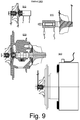
- Fig. 9 shows an example of a method 900 that includes component balancing 910 and 920, assembling components 930 and assembly balancing 940.
- a boreless compressor wheel fitted with a nose piece is balanced in two planes using sensors.
- the wheel may be driven with air, for example, using a fixed air spindle inserted into a shaft receptacle of the wheel.
- a shaft and turbine wheel assembly is balanced in two planes using sensors. In such a process the SWA may be placed in a bearing and driven by air.
- the assembly process 930 includes assembling a CHRA (Center Housing Rotating Assembly) using the balanced components.
- the assembly balancing process 940 may allow for reduction of unbalance, optionally including so-called "stack-up" unbalance (e.g., due to arrangement of various components of the CHRA).
- the CHRA is fitted to a balancing machine that includes accelerometers to facilitate measurement of unbalance while driving the rotating group of the CHRA.
- a balancing machine may also rely on magnetic field sensing, as mentioned.
- material is removed from the nose piece of the boreless compressor wheel.
- the nose piece may optionally be removed and the CHRA optionally disassembled followed by attachment of a new nose piece, component balancing of the new nose piece and boreless compressor wheel as a unit, assembly of the CHRA and assembly balancing.
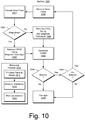
- Fig. 10 shows an example of a method 1000 for balancing a boreless compressor wheel.
- the method 1000 includes a balancing process 1010 that includes fitting a nose piece to a wheel 1012, measuring unbalance 1014 and removing material 1016. Such a process may be implemented by block 1028 and by block 1026.
- the method 1000 commences in a provision block 1022 that includes providing a nose piece.
- a decision block 1024 follows that decides whether the nose piece is made of or otherwise includes a magnetizable material. If the decision block 1024 decides that the nose piece is not magnetized, then the method 1000 continues in a balance block 1026; otherwise the method 1000 continues in a balance block 1028. As mentioned, the balance block 1026 and 1028 may implement the balancing process 1010.
- an assembly block 1032 After balancing, which may be component balancing for a boreless compressor wheel, an assembly block 1032 includes assembling a CHRA using the boreless compressor wheel subject to the balancing of block 1026 or block 1028. As shown in the example of Fig. 10 , another decision block 1036 decides whether further balancing should occur. If the decision block 1036 decides that no further balancing is to occur, the method 1000 may end in a packaging block 1040 that includes packaging the CHRA, optionally as a part of a turbocharger. However, if the decision block 1036 decides that further balancing is warranted, the method 1000 continues in yet another decision block 1044 that decides whether unbalance exists.
- the method 1000 continues to the packaging block 1040; otherwise, the method 1000 continues at a removal block 1048 that involves removal of the nose piece. For example, rather than scraping the boreless compressor wheel due to unacceptable unbalance, the method 1000 can provide for replacement of a nose piece with another nose piece.
- a nose piece may be unsuited for receiving one or more additional cuts responsive to a subsequent balancing process. Accordingly, where such situations arise, a nose piece may be simply removed and replaced with another nose piece (e.g., a fresh, uncut nose piece).
- a nose piece may be simply removed and replaced with another nose piece (e.g., a fresh, uncut nose piece).
- a process can reduce waste of boreless compressor wheels as material may be removed from a nose piece rather than a boreless wheel. In other words, waste can be shifted to nose pieces, which are easier to manufacture and of lesser cost than boreless compressor wheels.
- various acts may be performed by a controller (see, e.g., the controller 190 of Fig. 1 ), which may be a programmable control configured to operate according to instructions.
- one or more computer-readable media may include processor-executable instructions to instruct a computer (e.g., controller or other computing device) to perform one or more acts described herein.
- a computer-readable medium may be a storage medium (e.g., a device such as a memory chip, memory card, storage disk, etc.).
- a controller may be able to access such a storage medium (e.g., via a wired or wireless interface) and load information (e.g., instructions and/or other information) into memory (see, e.g., the memory 194 of Fig. 1 ).
- a controller may be an engine control unit (ECU) or other control unit (e.g., of a balancing unit).
Landscapes
- Engineering & Computer Science (AREA)
- Mechanical Engineering (AREA)
- General Engineering & Computer Science (AREA)
- Testing Of Balance (AREA)
- Structures Of Non-Positive Displacement Pumps (AREA)
- Supercharger (AREA)
Description
- Subject matter disclosed herein relates generally to turbomachinery for internal combustion engines and, in particular, to compressor wheels configured for receipt of a nose piece.
- Exhaust driven turbochargers include a rotating group that includes a turbine wheel and a compressor wheel that are connected to one another by a shaft. The shaft is typically rotatably supported within a center housing by one or more bearings (e.g., oil lubricated, air bearings, ball bearings, magnetic bearings, etc.). During operation, exhaust from an internal combustion engine drives a turbocharger's turbine wheel, which, in turn, drives the compressor wheel to boost charge air to the internal combustion engine.
- During operation, a turbocharger's rotating group must operate through a wide range of speeds. Depending on the size of the turbocharger, the maximum speed reached may be in excess of 200,000 rpm. Because of the wide operating range and the inherent design of the rotating group, most turbocharger rotating groups fit the definition of a "flexible rotor". Flexible rotors require a unique balancing process to assure that residual unbalance in all balance planes are controlled and results verified with a test of the unbalance response throughout the operating range. A well balanced turbocharger rotating group is essential for proper rotordynamic performance. Efforts to achieve low levels of unbalance help to assure shaft stability and minimize rotor deflection which in turn acts to reduce bearing loads. Reduced bearing loads result in improved durability and reduced noise (e.g., as resulting from transmitted vibration).
- To reduce vibration, turbocharger rotating group balancing includes component and assembly balancing. Individual components such as the compressor and turbine wheel assembly are typically balanced using a low rotational speed process while assembly (e.g., the completely assembled rotating group) are typically balanced using a high speed balancing process. Normally, the balance quality of the assembly is improved with a correction made on the compressor end of the rotating group alone.
- Compressor wheel designs may be of two main types, those with a through bore and those without a through bore, which are referred to as "boreless". For a compressor wheel with a through bore, the assembly process includes inserting a shaft in through the bore of the wheel and fixing the wheel to the shaft with a lock nut. The assembly is then installed in a high speed balancing machine for measurement and correction. The high speed balancer provides a means to operate the rotating group at the high speeds needed to provide adequate measurement and correction. Unbalance can be measured using instrumentation such as an accelerometer to provide an indication of unbalance in terms of vibration, or g's. In addition to the vibration response magnitude, the information provided by the high speed balancer can guide an operator, for example, by indicating where to remove material from the lock nut (e.g., phase angle of unbalance) to improve the balance. To measure unbalance phase, a high speed balancer may rely on a magnetic field sensor or an optical sensor. For a magnetic field sensor, the lock nut is magnetized (i.e., made of a magentizable material) whereas, for an optical sensor, one or more markings made on the lock nut or wheel may suffice. The magnetic method is generally preferred as being more accurate and reliable than the optical method.
- For conventional boreless compressor wheels, unfortunately, the aforementioned magnetized lock nut approach to balancing does not apply. Boreless compressor wheels are often used for applications where high compressor wheel stresses make it beneficial to eliminate the bore through the wheel to reduce stress at the center of the wheel, which can be a source of failure at high rotational speeds. To balance a boreless compressor wheel, as other types of wheels, material must be removed. However, the only option for a boreless compressor wheel is to remove the material directly from the wheel itself. Accordingly, problems can arise when, after removal of some material, further balancing is required. For example, if during a final rotating group balancing operation, an acceptable balance cannot be achieved by further removal of material, the compressor wheel must be scrapped. Specifically, a nose of a boreless compressor wheel can often handle only a single balance cut and cannot be cut again.
- Further, conventional boreless compressor wheels are typically made of aluminum, which is not a magentizable material. Accordingly, a magnetic field sensing approach to measuring unbalance cannot be used, which is unfortunate because, as mentioned, balancing approaches that use magnetization tend to be more efficient than optical approaches.
- Various technologies described herein pertain to compressor wheels and nose pieces that can enhance balancing and, consequently, reduced rotating group vibration.
-
US 2,602,683 discloses a rotor and separable shaft assembly for a turbomachine. -
EP 1 273 757 A1 discloses an assembly comprising a boreless compressor wheel that comprises a receptacle configured for receipt of a rotatable shaft and a turbine wheel that comprises a shaft having an end received by the receptacle of the boreless compressor wheel.EP 1 803 941 A1 discloses a turbocharger with a compressor impeller. -
GB 2 410 992 A -
DE 4 444 082 A discloses a turbo charger with a compressor rotor fixed to the stub end of a turbine shaft. -
EP 0 138 516 A1 discloses a centrifugal compressor apparatus. - The present invention in its various aspects is as set out in the appended claims.
- A more complete understanding of the various methods, devices, assemblies, systems, arrangements, etc., described herein, and equivalents thereof, may be had by reference to the following detailed description when taken in conjunction with examples shown in the accompanying drawings where:
-
Fig. 1 is a diagram of a turbocharger and an internal combustion engine along with a controller; -
Fig. 2 is two side views of conventional assemblies where each of the assemblies includes a compressor wheel having a through bore and a lock nut fixed to a shaft that extends through the through bore; -
Fig. 3 is two side views of conventional assemblies where each of the assemblies includes a boreless compressor wheel having a receptacle in receipt of an end of a shaft; -
Fig. 4 is a series of views of an example of a nose piece and examples of assemblies where each of the assemblies includes a boreless compressor wheel having a receptacle in receipt of a nose piece and another receptacle in receipt of an end of a shaft; -
Fig. 5 is a series of views of the nose pieces and the boreless compressor wheel receptacles ofFig. 4 ; -
Fig. 6 is a series of views of examples of nose pieces and examples of cuts for removal of material from a nose piece; -
Fig. 7 is a series of views of an example of a nose piece and a boreless compressor wheel along with a diagram of balancing equipment and a plot of measured unbalance versus rotational speed; -
Fig. 8 is a series of views of an example of a nose piece and a boreless compressor wheel; -
Fig. 9 is a diagram of an example of a method that includes component balancing, assembling and assembly balancing; and -
Fig. 10 is a block diagram of an example of a method that includes balancing a boreless compressor wheel that includes a nose piece. - Various components and assemblies are described herein. For example, components include nose pieces and boreless compressor wheels configured to receive such nose pieces. As described herein, an assembly includes inter alia a nose piece and a boreless compressor wheel that includes a nose end configured for receipt of the nose piece and a receptacle at a base end configured for receipt of a rotatable shaft. Such a shaft may be a turbocharger shaft or other rotatable shaft (e.g., driven by a belt, a chain, electric motor, etc.). Accordingly, a boreless compressor wheel with a nose piece or balanced using a nose piece is used for turbocharger, supercharger or other applications.
- As described herein, a nose piece facilitates balancing. For example, a nose piece may be made of a magnetizable material that allows for measuring unbalance via a magnetic field sensor. Material is removed from a nose piece to improve balance (e.g., based on measured unbalance). Accordingly, a nose piece facilitates measurement of unbalance, balancing or measurement of unbalance and balancing.
- In various examples, a boreless compressor wheel can be one in which there is a single compressor wheel or one that includes two compressor impellers or faces. For example, a wheel with two compressor impellers (e.g., mounted in a back to back fashion) may be operated in parallel or in series. In other words, each impeller face may be directed to a dedicated diffuser section, a dedicated volute, a shared diffuser section, a shared volute, etc.
- In various examples, a nose piece includes a stem and a nose end of a boreless compressor wheel includes a receptacle configured to receive the stem. In an alternative example, a nose piece can include an opening and a nose end of a boreless compressor wheel can include a stem configured for insertion into the opening of the nose piece.
- As described herein, a nose piece may be attached to a boreless compressor wheel by any of a variety of mechanisms. For example, features of a boreless compressor wheel and a nose piece may be configured for press fitting the nose piece on to the boreless compressor wheel, a boreless compressor wheel and a nose piece may include cooperative threads for threading the nose piece on to the boreless compressor wheel, or a nose piece may be configured to shrink fit on to a boreless compressor wheel (e.g., heated to expand and then cooled to shrink fit).
- Whether for purposes of attachment or for rotation of an assembly, a nose piece may include an internal drive, an external drive or both an internal drive and an external drive, for example, where such drives are configured to cooperate with a tool or tools.
- As described herein, an assembly includes inter alia a boreless compressor wheel that includes a nose piece with one or more balance cuts (e.g., to provide for balance of the assembly) and a receptacle configured for receipt of a shaft; and a turbine wheel that includes a shaft having an end received by the receptacle of the boreless compressor wheel. Such an assembly may include a nose piece made of a magnetizable material.
- As described herein, an exemplary method can include fitting a nose piece to a boreless compressor wheel, measuring unbalance, and, based in part on the measuring, removing material from the nose piece. An exemplary method may include removing a nose piece from a boreless compressor wheel and fitting another nose piece to the boreless compressor wheel. With respect to measuring unbalance, various techniques may be used, for example, consider a technique that includes rotating a boreless compressor wheel and a nose piece and measuring magnetic field properties associated with the nose piece. As described herein, an exemplary method can include assembling a turbocharger that includes a boreless compressor wheel and a nose piece having at least some material removed.
- Below, an example of a turbocharged engine system is described followed by various examples of components, assemblies, methods, etc.
- Turbochargers are frequently utilized to increase output of an internal combustion engine. Referring to
Fig. 1 , aconventional system 100 includes aninternal combustion engine 110 and aturbocharger 120. Theinternal combustion engine 110 includes anengine block 118 housing one or more combustion chambers that operatively drive a shaft 112 (e.g., via pistons). As shown inFig. 1 , anintake port 114 provides a flow path for air to theengine block 118 while anexhaust port 116 provides a flow path for exhaust from theengine block 118. - The
turbocharger 120 acts to extract energy from the exhaust and to provide energy to intake air, which may be combined with fuel to form combustion gas. As shown inFig. 1 , theturbocharger 120 includes anair inlet 134, ashaft 122, acompressor 124, aturbine 126, ahousing 128 and anexhaust outlet 136. Thehousing 128 may be referred to as a center housing as it is disposed between thecompressor 124 and theturbine 126. Theshaft 122 may be a shaft assembly that includes a variety of components. In the example ofFig. 1 , a wastegate valve (or simply wastegate) 135 is positioned proximate to the inlet of theturbine 126. Thewastegate valve 135 can be controlled to allow exhaust from theexhaust port 116 to bypass theturbine 126. - In
Fig. 1 , an example of acontroller 190 is shown as including one ormore processors 192,memory 194 and one ormore interfaces 196. Such a controller may include circuitry such as circuitry of an engine control unit. As described herein, various methods or techniques may optionally be implemented in conjunction with a controller, for example, through control logic. Control logic may depend on one or more engine operating conditions (e.g., turbo rpm, engine rpm, temperature, load, lubricant, cooling, etc.). For example, sensors may transmit information to thecontroller 190 via the one ormore interfaces 196. Control logic may rely on such information and, in turn, thecontroller 190 may output control signals to control engine operation. Thecontroller 190 may be configured to control lubricant flow, temperature, a variable geometry assembly (e.g., variable geometry compressor or turbine), a wastegate, an electric motor, or one or more other components associated with an engine, a turbocharger (or turbochargers), etc. More generally, as described herein, a controller may be configured for use in another process such as a balancing process. -
Fig. 2 shows examples of twoconventional assemblies compressor wheel bore lock nut shaft bore compressor wheel 270 includes two impeller faces 275 and 277 while thecompressor wheel 220 includes only a single impeller face. - In the examples of
Fig. 2 , each of theshafts respective turbine wheel shafts respective thrust collars respective bearings shaft 201 includes acompressor wheel portion 202, athrust collar portion 203, a compressorjournal bearing portion 204, a bearingportion 205, and a turbine journal bearing portion 206. Theshaft 251 also includes acompressor wheel portion 252, athrust collar portion 253, a compressorjournal bearing portion 254, a bearingportion 255, and a turbinejournal bearing portion 256. Various axial dimensions are shown for thebearings 215 and 265 (zB), thethrust collars 213 and 263 (zB), thecompressor wheels 220 and 270 (zC), and thelock nuts 210 and 260 (zN). - For the
assembly 200, thecompressor wheel 220 includes anose end 224 that abuts thelock nut 210 and abase end 226 that abuts thethrust collar 213. Thecompressor wheel 220 has a minimum radius rC-Min at itsnose end 224 and has a maximum wheel radius rC-Max at anedge 228 that coincides with a so-called z-plane. - For the
assembly 250, thecompressor wheel 270 includes anose end 274 that abuts thelock nut 260 and abase end 276 that abuts thethrust collar 263. Thecompressor wheel 270 has a minimum radius rC-Min at itsnose end 274 and has a maximum wheel radius rC-Max at anedge 278 that coincides with a so-called z-plane. - With respect to balancing, a lock nut is typically made of steel and suitable measuring unbalance through magnetic field sensing. During a balancing process, one or more cuts may be made in a lock nut according to information provided by a balancing machine (e.g., a VSR).
-
Fig. 3 shows examples of twoconventional assemblies boreless compressor wheel receptacle shaft compressor wheel 370 includes two impeller faces 375 and 377 while thecompressor wheel 320 includes only a single impeller face. - In the examples of
Fig. 3 , each of theshafts respective turbine wheel shafts respective thrust collars respective bearings shaft 301 includes acompressor wheel portion 302, athrust collar portion 303, a compressorjournal bearing portion 304, a bearingportion 305, and a turbinejournal bearing portion 306. Theshaft 351 also includes acompressor wheel portion 352, athrust collar portion 353, a compressorjournal bearing portion 354, a bearingportion 355, and a turbinejournal bearing portion 356. Various axial dimensions are shown for thebearings 315 and 365 (zB), thethrust collars 313 and 363 (zB), thecompressor wheels 320 and 370 (zC), and the insertion depth of theportions shafts respective receptacles 322 and 352 (ZSI). - For the
assembly 300, thecompressor wheel 320 includes anose end 324 and abase end 326 that abuts thethrust collar 313. Thecompressor wheel 320 has a maximum wheel radius rC-Max at anedge 328 that coincides with a so-called z-plane. - For the
assembly 350, thecompressor wheel 370 includes anose end 374 and abase end 376 that abuts thethrust collar 363. Thecompressor wheel 370 has a maximum wheel radius rC-Max at anedge 378 that coincides with a so-called z-plane. - With respect to balancing, one or more markings are typically made on a boreless compressor wheel followed by measuring unbalance through optical sensing of such marking or markings. During a balancing process, one or more cuts are made in a nose end of a boreless compressor wheel according to information provided by a balancing machine (e.g., a VSR).
-
Fig. 4 shows examples ofassemblies boreless compressor wheel boreless compressor wheels receptacle respective nose piece receptacle end portion respective shaft compressor wheel 470 includes two impeller faces 475 and 477 while thecompressor wheel 420 includes only a single impeller face. - In the examples of
Fig. 4 , each of theshafts respective turbine wheel shafts respective thrust collars respective bearings shaft 401 includes theend portion 402, athrust collar portion 403, a compressorjournal bearing portion 404, a bearingportion 405, and a turbinejournal bearing portion 406. Theshaft 451 also includes anend portion 452, athrust collar portion 453, a compressorjournal bearing portion 454, a bearingportion 455, and a turbinejournal bearing portion 456. Various axial dimensions are shown for thebearings 415 and 465 (zB), thethrust collars 413 and 463 (zB), thecompressor wheels 420 and 470 (zC), the insertion depth of theportions shafts respective receptacles 422 and 452 (zSI), the insertion depth of stems 431 and 481 of thenose pieces respective receptacles 421 and 471 (zNI), and for thenose pieces 430 and 480 (ZN). - For the
assembly 400, thecompressor wheel 420 includes anose end 424 that abuts thenose piece 430 and abase end 426 that abuts thethrust collar 413. Thecompressor wheel 420 has a minimum wheel radius rC-Min at thenose end 424 and a maximum wheel radius rC-Max at anedge 428 that coincides with a so-called z-plane. - For the
assembly 450, thecompressor wheel 470 includes anose end 474 that abuts thenose piece 480 and abase end 476 that abuts thethrust collar 463. Thecompressor wheel 470 has a minimum wheel radius rC-Min at thenose end 474 and a maximum wheel radius rC-Max at anedge 478 that coincides with a so-called z-plane. -
Fig. 4 also shows top views of thenose pieces internal drives nose piece 430 as including an optional external drive disposed between ahead portion 432 and thestem 431. In the example ofFig. 4 , thenose piece 480 is also shown as including an optionalexternal drive 483 disposed between ahead portion 482 and astem portion 481. Such drives can allow for rotation of at least a nose piece, for example, to attach a nose piece to a boreless compressor wheel or, for example, to rotate a nose piece and boreless compressor wheel as an assembly. - With respect to balancing, a nose piece allows for measurement of unbalance, balancing or measurement of unbalance and balancing. With respect to balancing, during a balancing process, one or more cuts are may made in a nose piece attached to a boreless compressor wheel according to information provided by a balancing machine (e.g., a VSR). As described herein, a nose piece may be made of steel, aluminum or another material.
-
Fig. 5 shows various views of thenose pieces compressor wheel receptacles Fig. 4 . Thenose pieces nose pieces nose pieces Fig. 5 , a neck is disposed between the pilot surfaces P1 and P2, which has a radius rnk and an axial length znk. Other dimensions of thenose pieces Fig. 5 include an axial head length (zh) and a head radius (rh), an axial external drive length (zed) and an external drive radius (red), and an axial internal drive length (zid) and an internal drive radius (rid). In general, a nose piece has a head portion of sufficient mass such that removal of some of the mass (e.g., via cutting or other technique) can improve balance of nose piece and boreless wheel assembly. - As described herein, various features of a nose piece may cooperate with one or more features of a boreless compressor wheel receptacle. For example, the
receptacle 421 of theboreless compressor wheel 420 and thereceptacle 471 of theboreless compressor wheel 470 may include a surface with an axial length zCP1 and a radius rCP1 and a surface with an axial length zCP2 and a radius rCP2 where such surfaces cooperate with a pilot surface of a portion of a nose piece such as the pilot surfaces P1 and P2 of thenose pieces Fig. 4 , thereceptacles Fig. 4 , thereceptacles boreless wheel 420 or theboreless wheel 470 may optionally be characterized as including two axially aligned and opposing receptacles that do not extend to a z-plane of a wheel. Hence, as shown inFig. 4 , such a wheel has a solid portion (i.e., boreless portion) located axially between the two opposing receptacles. As described herein, a receptacle may be shaped at a distal end (e.g., closed end) to reduce stress. - As described herein, a portion of a nose piece may include threads while a portion of a boreless compressor wheel includes cooperating threads. Accordingly, a nose piece may be rotated with respect to a boreless compressor wheel to secure the nose piece to the wheel. Other mechanisms for attachment may include bayonet, press fit via appropriate clearances, etc. As described herein, a pilot surface or other feature may help align a nose piece along a rotational axis of a boreless compressor wheel.
-
Fig. 6 shows some examples ofnose pieces nose piece 650. As shown inFig. 6 , thenose piece 610 includes a threadedstem 611 and anexternal drive 613. As described herein, a tool such as a wrench may engage theexternal drive 613 to rotate thenose piece 610 with respect to a boreless compressor wheel to thereby secure thenose piece 610 to the boreless compressor wheel. Once secured, theexternal drive 613 may allow for rotation of thenose piece 610 and the boreless compress wheel as a unit. - As shown in
Fig. 6 , thenose piece 620 includes a threadedstem 621 and aninternal drive 625. As described herein, a tool such as a hex wrench may engage theinternal drive 625 to rotate thenose piece 620 with respect to a boreless compressor wheel to thereby secure thenose piece 620 to the boreless compressor wheel. Once secured, theinternal drive 625 may allow for rotation of thenose piece 620 and the boreless compress wheel as a unit. - As shown in
Fig. 6 , thenose piece 630 includes a threadedstem 631 without any pilot surfaces and anexternal drive 633. As described herein, a tool such as a wrench may engage theexternal drive 633 to rotate thenose piece 630 with respect to a boreless compressor wheel to thereby secure thenose piece 630 to the boreless compressor wheel. Once secured, theexternal drive 633 may allow for rotation of thenose piece 630 and the boreless compress wheel as a unit. - As described herein, should removal of a nose piece from a boreless compressor wheel be desired or required, a drive or drives may be suitable used in conjunction with an appropriate tool or tools to remove the nose piece. For example, the
drives nose pieces Fig. 6 show threads, as described herein, other mechanisms may be used to secure a nose piece to a boreless compressor wheel. -
Fig. 6 also showsvarious balance cuts 650 with respect to anose piece 670, anose piece 680 and anose piece 690, which are to be fitted to aboreless compressor wheel 660. As shown, the cuts may be made from an end of a nose piece and extend axially downward. In such a manner, material is removed to improve balance. As described herein, phase information may guide an operator as to angle of a cut. While all of thecuts 650 are shown as being aligned (e.g., centered at 90 degrees), a cut may be aligned at any angle about a nose piece and made in any manner or shape. -
Fig. 7 shows an example of anose piece 710 and aboreless compressor wheel 720 along with balancingequipment plot 798 of measured unbalance versus rotational speed. In the example ofFig. 7 , the nose piece includes astem 711 and ahead 712 while theboreless compressor wheel 720 includes areceptacle 722 with an axial length zCP and a radius rCP. Accordingly, thenose piece 710 may be fitted to theboreless compressor wheel 720 by inserting thestem 711 into thereceptacle 722. As described herein, a nose piece may be attached to a boreless compressor wheel via any of a variety of mechanisms, such as, for example, threads, press fit, etc. - In the example of
Fig. 7 , thenose piece 710 is made of a magnetizable material such as steel. In preparation for measurement of unbalance, thenose piece 710 may be magnetized, for example, magnetizing may occur by passing a magnet closely by thenose piece 710. For measuring unbalance, thenose piece 710 as affixed to theboreless compressor wheel 720 may be placed in ashroud 797 and rotated such that amagnetic field sensor 795 can measure unbalance. In turn, such information may be plotted as shown in theplot 798 as g-level versus rpm. Theplot 798 shows a solid line that represents unbalance prior to removal of material from thenose piece 710, theboreless compressor wheel 720 or from thenose piece 710 and theboreless compressor wheel 720 as well as a dashed line that represents a reduced g-level (or vibration unbalance) after removal of material. As described herein, a nose piece made from or including a magnetizable material can allow for magnetic field-based measurement of unbalance of a boreless compressor wheel made of a non-magnetizable material. Further, such a nose piece can allow for alteration of a center of mass of an assembly to improve balance (e.g., by removal of material via a cut or other technique). -
Fig. 8 shows an example of anose piece 810 and aboreless compressor wheel 820. Such a nose piece may be for purposes of sensing unbalance using a magnetic field sensor, for purposes of material removal to improve balance or a combination of both sensing and material removal to improve balance. In the example ofFig. 8 , thenose piece 810 includes anopening 811 with a radius ri while theboreless compressor wheel 820 includes astem portion 821 with a radius rCP. Other dimensions shown inFig. 8 include a nose piece outer radius (rh), a nose piece axial length (zh) and a stem axial length (zCP). - As shown in
Fig. 8 , thenose piece 810 is received by thestem 821 of theboreless compressor wheel 820. Clearances between theopening 811 and thestem 821 may provide for a secure press fit. As another example, a nose piece may be provided that responds to heating or other processing to shrink fit securely onto thestem 821. As described herein, such a fit may be relatively permanent or allow for reversal if removal and replacement of the nose piece is desired. - Further, in the example of
Fig. 8 , thenose piece 810 may be made of or include a magnetizable material while theboreless compressor wheel 820 may be made of a non-magnetizable material. Where balancing requires removal of material, material is removed from thenose piece 810, from theboreless compressor wheel 820 or from both thenose piece 810 and theboreless compressor wheel 820. The thickness of thenose piece 810 must be sufficient to receive a cut for purposes of improving balance of a nose piece and boreless wheel assembly. As shown inFig. 6 ,balance cuts 650 extend axially downward. With respect to thenose piece 810, cuts may extend axially downward a distance less than the axial length (zh) of the nose piece (e.g., to maintain sufficient integrity of the nose piece). -
Fig. 9 shows an example of amethod 900 that includes component balancing 910 and 920, assemblingcomponents 930 and assembly balancing 940. In thebalancing process 910, a boreless compressor wheel fitted with a nose piece is balanced in two planes using sensors. In such a process, the wheel may be driven with air, for example, using a fixed air spindle inserted into a shaft receptacle of the wheel. In thebalancing process 920, a shaft and turbine wheel assembly (SWA) is balanced in two planes using sensors. In such a process the SWA may be placed in a bearing and driven by air. - After component balancing, the
assembly process 930 includes assembling a CHRA (Center Housing Rotating Assembly) using the balanced components. Once assembled, theassembly balancing process 940 may allow for reduction of unbalance, optionally including so-called "stack-up" unbalance (e.g., due to arrangement of various components of the CHRA). In theassembly balancing process 940, the CHRA is fitted to a balancing machine that includes accelerometers to facilitate measurement of unbalance while driving the rotating group of the CHRA. Such a balancing machine may also rely on magnetic field sensing, as mentioned. As described herein, to correct unbalance, material is removed from the nose piece of the boreless compressor wheel. If the nose piece cannot provide for further removal of material, the nose piece may optionally be removed and the CHRA optionally disassembled followed by attachment of a new nose piece, component balancing of the new nose piece and boreless compressor wheel as a unit, assembly of the CHRA and assembly balancing. -
Fig. 10 shows an example of amethod 1000 for balancing a boreless compressor wheel. Themethod 1000 includes abalancing process 1010 that includes fitting a nose piece to awheel 1012, measuringunbalance 1014 and removingmaterial 1016. Such a process may be implemented byblock 1028 and by block 1026. - The
method 1000 commences in aprovision block 1022 that includes providing a nose piece. Adecision block 1024 follows that decides whether the nose piece is made of or otherwise includes a magnetizable material. If thedecision block 1024 decides that the nose piece is not magnetized, then themethod 1000 continues in a balance block 1026; otherwise themethod 1000 continues in abalance block 1028. As mentioned, thebalance block 1026 and 1028 may implement thebalancing process 1010. - After balancing, which may be component balancing for a boreless compressor wheel, an
assembly block 1032 includes assembling a CHRA using the boreless compressor wheel subject to the balancing of block 1026 orblock 1028. As shown in the example ofFig. 10 , anotherdecision block 1036 decides whether further balancing should occur. If thedecision block 1036 decides that no further balancing is to occur, themethod 1000 may end in apackaging block 1040 that includes packaging the CHRA, optionally as a part of a turbocharger. However, if thedecision block 1036 decides that further balancing is warranted, themethod 1000 continues in yet anotherdecision block 1044 that decides whether unbalance exists. If unbalance does not exist or is otherwise acceptable, themethod 1000 continues to thepackaging block 1040; otherwise, themethod 1000 continues at aremoval block 1048 that involves removal of the nose piece. For example, rather than scraping the boreless compressor wheel due to unacceptable unbalance, themethod 1000 can provide for replacement of a nose piece with another nose piece. - Specifically, where a nose piece has been cut during a preliminary balancing process, it may be unsuited for receiving one or more additional cuts responsive to a subsequent balancing process. Accordingly, where such situations arise, a nose piece may be simply removed and replaced with another nose piece (e.g., a fresh, uncut nose piece). Such a process can reduce waste of boreless compressor wheels as material may be removed from a nose piece rather than a boreless wheel. In other words, waste can be shifted to nose pieces, which are easier to manufacture and of lesser cost than boreless compressor wheels.
- As described herein, various acts may be performed by a controller (see, e.g., the
controller 190 ofFig. 1 ), which may be a programmable control configured to operate according to instructions. As described herein, one or more computer-readable media may include processor-executable instructions to instruct a computer (e.g., controller or other computing device) to perform one or more acts described herein. A computer-readable medium may be a storage medium (e.g., a device such as a memory chip, memory card, storage disk, etc.). A controller may be able to access such a storage medium (e.g., via a wired or wireless interface) and load information (e.g., instructions and/or other information) into memory (see, e.g., thememory 194 ofFig. 1 ). As described herein, a controller may be an engine control unit (ECU) or other control unit (e.g., of a balancing unit). - Although some examples of methods, devices, systems, arrangements, etc., have been illustrated in the accompanying Drawings and described in the foregoing Detailed Description, it will be understood that the example embodiments disclosed are not limiting, but are capable of numerous rearrangements, modifications and substitutions without departing from the following claims.
Claims (15)
- An assembly comprising:a boreless compressor wheel sub-assembly that comprisesa nose piece (430, 480) with one or more balance cuts anda boreless compressor wheel (420, 470) that comprises a nose end configured for receipt of the nose piece (430, 480) and a receptacle (422, 452) configured for receipt of a rotatable shaft (451); anda turbine wheel (440, 490) that comprises a shaft having an end received by the receptacle (422, 452) of the boreless compressor wheel (420, 470).
- The assembly of claim 1 wherein the nose piece (430, 480) comprises a magnetizable material.
- The assembly of claim 1 wherein the one or more balance cuts provide for balance of the assembly.
- The assembly of claim 1 wherein the boreless compressor wheel (420, 470) comprises two impeller faces.
- The assembly of claim 1 wherein the nose piece (430, 480) comprises a stem (431, 481) and wherein the nose end of the boreless compressor wheel comprises a receptacle (421, 471) configured to receive the stem.
- The assembly of claim 1 wherein the nose piece (430, 480) comprises an opening and wherein the nose end of the boreless compressor wheel comprises a stem configured for insertion into the opening of the nose piece.
- The assembly of claim 1 wherein the boreless compressor wheel comprises a non-magnetizable material.
- The assembly of claim 1 wherein the nose piece (430, 480) comprises a replaceable nose piece.
- The assembly of claim 1 wherein features of the boreless compressor wheel (420, 470) and the nose piece (430, 480) comprise features configured for press fitting the nose piece on to the boreless compressor wheel (420, 470).
- The assembly of claim 1 wherein the boreless compressor wheel (420, 470) and the nose piece (430, 480) comprise cooperative threads for threading the nose piece on to the boreless compressor wheel.
- The assembly of claim 1 wherein the nose piece (430, 480) comprises a nose piece configured to shrink fit on to the boreless compressor wheel.
- The assembly of claim 1 wherein the nose piece (430, 480) comprises an internal drive for rotating at least the nose piece.
- The assembly of claim 1 wherein the nose piece (430, 480) comprises an external drive for rotating at least the nose piece.
- The assembly of claim 1 wherein the nose piece (430, 480) comprises an internal drive and an external drive.
- A turbocharger comprising the assembly of any one of the preceding claims.
Applications Claiming Priority (1)
| Application Number | Priority Date | Filing Date | Title |
|---|---|---|---|
| US13/161,056 US8801379B2 (en) | 2011-06-15 | 2011-06-15 | Wheel and replaceable nose piece |
Publications (3)
| Publication Number | Publication Date |
|---|---|
| EP2535592A2 EP2535592A2 (en) | 2012-12-19 |
| EP2535592A3 EP2535592A3 (en) | 2013-05-15 |
| EP2535592B1 true EP2535592B1 (en) | 2018-05-02 |
Family
ID=46148730
Family Applications (1)
| Application Number | Title | Priority Date | Filing Date |
|---|---|---|---|
| EP12169668.6A Active EP2535592B1 (en) | 2011-06-15 | 2012-05-25 | Assembly with Compressor Wheel and Turbine wheel |
Country Status (3)
| Country | Link |
|---|---|
| US (1) | US8801379B2 (en) |
| EP (1) | EP2535592B1 (en) |
| CN (1) | CN102828993B (en) |
Families Citing this family (10)
| Publication number | Priority date | Publication date | Assignee | Title |
|---|---|---|---|---|
| FR2949858B1 (en) * | 2009-09-08 | 2012-03-23 | Snecma | EQUILIBRATION DEVICE AND METHOD |
| WO2015116688A1 (en) * | 2014-01-30 | 2015-08-06 | Borgwarner Inc. | Exhaust-gas turbocharger |
| DE102014215441A1 (en) * | 2014-08-05 | 2016-02-11 | Bosch Mahle Turbo Systems Gmbh & Co. Kg | Method for producing a rotor of a charging device |
| DE102015218428A1 (en) * | 2014-10-03 | 2016-04-07 | Borgwarner Inc., Patent Department | DEVICES AND METHOD FOR ADJUSTING THE BALANCE OF THE ROTATION ARRANGEMENT OF A TURBOCHARGER |
| US10272542B2 (en) | 2015-05-08 | 2019-04-30 | Balance Technology, Inc. | Abrasive water jet balancing apparatus and method for rotating components |
| DE102015111962B4 (en) * | 2015-07-23 | 2022-07-28 | Rolls-Royce Solutions GmbH | Exhaust gas turbocharger with a magnetic bearing unit and an internal combustion engine with an exhaust gas turbocharger and a method for controlling an exhaust gas turbocharger |
| US9957981B1 (en) | 2017-04-13 | 2018-05-01 | Borgwarner Inc. | Turbocharger having compressor portion with imbalance correction region |
| CN107939727B (en) * | 2017-11-20 | 2023-07-14 | 珠海格力电器股份有限公司 | Fan subassembly and have its air conditioner |
| US11118462B2 (en) | 2019-01-24 | 2021-09-14 | Pratt & Whitney Canada Corp. | Blade tip pocket rib |
| US11371359B2 (en) | 2020-11-26 | 2022-06-28 | Pratt & Whitney Canada Corp. | Turbine blade for a gas turbine engine |
Family Cites Families (11)
| Publication number | Priority date | Publication date | Assignee | Title |
|---|---|---|---|---|
| US2602683A (en) * | 1945-03-03 | 1952-07-08 | Sulzer Ag | Rotor for turbomachines |
| EP0138516A1 (en) | 1983-10-07 | 1985-04-24 | Household Manufacturing, Inc. | Centrifugal compressor wheel and its mounting on a shaft |
| DE4444082A1 (en) | 1994-12-10 | 1996-06-13 | Abb Management Ag | Engine exhaust turbocharger |
| DE59710695D1 (en) * | 1997-09-19 | 2003-10-09 | Abb Turbo Systems Ag Baden | Compressor wheel attachment for high-speed turbo machines |
| US6499969B1 (en) | 2000-05-10 | 2002-12-31 | General Motors Corporation | Conically jointed turbocharger rotor |
| US6481970B2 (en) | 2000-06-28 | 2002-11-19 | Honeywell International Inc. | Compressor wheel with prestressed hub and interference fit insert |
| JP2005226469A (en) * | 2004-02-10 | 2005-08-25 | Komatsu Ltd | Compressor impeller and shaft coupling structure |
| DE102004021484B4 (en) * | 2004-04-30 | 2018-11-29 | Böllhoff Verbindungstechnik GmbH | Method for producing a connection arrangement |
| WO2006043556A1 (en) | 2004-10-19 | 2006-04-27 | Komatsu Ltd. | Turbo machine, compressor impeller used for turbo machine, and method of manufacturing turbo machine |
| DE102007027235B4 (en) | 2007-06-13 | 2010-08-19 | Continental Automotive Gmbh | Magnetized nut for mounting a compressor wheel of an exhaust gas turbocharger on the turbo shaft and method for producing such |
| WO2010111133A2 (en) | 2009-03-26 | 2010-09-30 | Borgwarner Inc. | Reduction of turbocharger core unbalance with balance washer |
-
2011
- 2011-06-15 US US13/161,056 patent/US8801379B2/en active Active
-
2012
- 2012-05-25 EP EP12169668.6A patent/EP2535592B1/en active Active
- 2012-06-14 CN CN201210195994.8A patent/CN102828993B/en active Active
Non-Patent Citations (1)
| Title |
|---|
| None * |
Also Published As
| Publication number | Publication date |
|---|---|
| US20120321458A1 (en) | 2012-12-20 |
| CN102828993B (en) | 2017-09-12 |
| EP2535592A3 (en) | 2013-05-15 |
| US8801379B2 (en) | 2014-08-12 |
| CN102828993A (en) | 2012-12-19 |
| EP2535592A2 (en) | 2012-12-19 |
Similar Documents
| Publication | Publication Date | Title |
|---|---|---|
| US8801379B2 (en) | Wheel and replaceable nose piece | |
| EP2065564B1 (en) | Turbocharger center housing and rotating assembly | |
| EP2065562B1 (en) | Method and device for balancing of a turbocharger bearing and shaft wheel assembly | |
| US11008868B2 (en) | Balancing method for a turbocharger | |
| EP2592280B1 (en) | Compressor wheel shaft with recessed portion | |
| EP1706590B1 (en) | Titanium compressor wheel | |
| EP1895164B1 (en) | Ball bearing turbocharger balancer | |
| US7722336B2 (en) | Compressor wheel | |
| EP3333363A2 (en) | Turbocharger assembly | |
| EP3333371B1 (en) | System for a turbocharger | |
| KR20090024153A (en) | How to modify the motor rotor and its rotational balance | |
| US20150322793A1 (en) | Method for turbine wheel balance stock removal | |
| JP2005226469A (en) | Compressor impeller and shaft coupling structure | |
| EP1413764A2 (en) | Compressor wheel assembly | |
| US20080118377A1 (en) | Exhaust Gas Turbo Charger | |
| CN108223133B (en) | Turbocharger assembly | |
| EP3760874B1 (en) | Turbo charger assembly and method for balancing said turbo charger assembly | |
| CN115962146B (en) | Rotor with balancing feature and balancing method | |
| EP3406848B1 (en) | Turbocharger having compressor portion with imbalance correction region |
Legal Events
| Date | Code | Title | Description |
|---|---|---|---|
| PUAI | Public reference made under article 153(3) epc to a published international application that has entered the european phase |
Free format text: ORIGINAL CODE: 0009012 |
|
| 17P | Request for examination filed |
Effective date: 20120525 |
|
| AK | Designated contracting states |
Kind code of ref document: A2 Designated state(s): AL AT BE BG CH CY CZ DE DK EE ES FI FR GB GR HR HU IE IS IT LI LT LU LV MC MK MT NL NO PL PT RO RS SE SI SK SM TR |
|
| AX | Request for extension of the european patent |
Extension state: BA ME |
|
| PUAL | Search report despatched |
Free format text: ORIGINAL CODE: 0009013 |
|
| AK | Designated contracting states |
Kind code of ref document: A3 Designated state(s): AL AT BE BG CH CY CZ DE DK EE ES FI FR GB GR HR HU IE IS IT LI LT LU LV MC MK MT NL NO PL PT RO RS SE SI SK SM TR |
|
| AX | Request for extension of the european patent |
Extension state: BA ME |
|
| RIC1 | Information provided on ipc code assigned before grant |
Ipc: F04D 29/26 20060101AFI20130410BHEP Ipc: F04D 29/66 20060101ALI20130410BHEP |
|
| 17Q | First examination report despatched |
Effective date: 20130507 |
|
| RAP1 | Party data changed (applicant data changed or rights of an application transferred) |
Owner name: HONEYWELL INTERNATIONAL INC. |
|
| GRAP | Despatch of communication of intention to grant a patent |
Free format text: ORIGINAL CODE: EPIDOSNIGR1 |
|
| STAA | Information on the status of an ep patent application or granted ep patent |
Free format text: STATUS: GRANT OF PATENT IS INTENDED |
|
| INTG | Intention to grant announced |
Effective date: 20171215 |
|
| GRAS | Grant fee paid |
Free format text: ORIGINAL CODE: EPIDOSNIGR3 |
|
| GRAA | (expected) grant |
Free format text: ORIGINAL CODE: 0009210 |
|
| STAA | Information on the status of an ep patent application or granted ep patent |
Free format text: STATUS: THE PATENT HAS BEEN GRANTED |
|
| AK | Designated contracting states |
Kind code of ref document: B1 Designated state(s): AL AT BE BG CH CY CZ DE DK EE ES FI FR GB GR HR HU IE IS IT LI LT LU LV MC MK MT NL NO PL PT RO RS SE SI SK SM TR |
|
| REG | Reference to a national code |
Ref country code: GB Ref legal event code: FG4D |
|
| REG | Reference to a national code |
Ref country code: CH Ref legal event code: EP Ref country code: AT Ref legal event code: REF Ref document number: 995566 Country of ref document: AT Kind code of ref document: T Effective date: 20180515 |
|
| REG | Reference to a national code |
Ref country code: FR Ref legal event code: PLFP Year of fee payment: 7 |
|
| REG | Reference to a national code |
Ref country code: DE Ref legal event code: R096 Ref document number: 602012045822 Country of ref document: DE Ref country code: IE Ref legal event code: FG4D |
|
| REG | Reference to a national code |
Ref country code: NL Ref legal event code: MP Effective date: 20180502 |
|
| REG | Reference to a national code |
Ref country code: LT Ref legal event code: MG4D |
|
| PG25 | Lapsed in a contracting state [announced via postgrant information from national office to epo] |
Ref country code: FI Free format text: LAPSE BECAUSE OF FAILURE TO SUBMIT A TRANSLATION OF THE DESCRIPTION OR TO PAY THE FEE WITHIN THE PRESCRIBED TIME-LIMIT Effective date: 20180502 Ref country code: BG Free format text: LAPSE BECAUSE OF FAILURE TO SUBMIT A TRANSLATION OF THE DESCRIPTION OR TO PAY THE FEE WITHIN THE PRESCRIBED TIME-LIMIT Effective date: 20180802 Ref country code: SE Free format text: LAPSE BECAUSE OF FAILURE TO SUBMIT A TRANSLATION OF THE DESCRIPTION OR TO PAY THE FEE WITHIN THE PRESCRIBED TIME-LIMIT Effective date: 20180502 Ref country code: ES Free format text: LAPSE BECAUSE OF FAILURE TO SUBMIT A TRANSLATION OF THE DESCRIPTION OR TO PAY THE FEE WITHIN THE PRESCRIBED TIME-LIMIT Effective date: 20180502 Ref country code: LT Free format text: LAPSE BECAUSE OF FAILURE TO SUBMIT A TRANSLATION OF THE DESCRIPTION OR TO PAY THE FEE WITHIN THE PRESCRIBED TIME-LIMIT Effective date: 20180502 Ref country code: NO Free format text: LAPSE BECAUSE OF FAILURE TO SUBMIT A TRANSLATION OF THE DESCRIPTION OR TO PAY THE FEE WITHIN THE PRESCRIBED TIME-LIMIT Effective date: 20180802 |
|
| PG25 | Lapsed in a contracting state [announced via postgrant information from national office to epo] |
Ref country code: NL Free format text: LAPSE BECAUSE OF FAILURE TO SUBMIT A TRANSLATION OF THE DESCRIPTION OR TO PAY THE FEE WITHIN THE PRESCRIBED TIME-LIMIT Effective date: 20180502 Ref country code: RS Free format text: LAPSE BECAUSE OF FAILURE TO SUBMIT A TRANSLATION OF THE DESCRIPTION OR TO PAY THE FEE WITHIN THE PRESCRIBED TIME-LIMIT Effective date: 20180502 Ref country code: LV Free format text: LAPSE BECAUSE OF FAILURE TO SUBMIT A TRANSLATION OF THE DESCRIPTION OR TO PAY THE FEE WITHIN THE PRESCRIBED TIME-LIMIT Effective date: 20180502 Ref country code: GR Free format text: LAPSE BECAUSE OF FAILURE TO SUBMIT A TRANSLATION OF THE DESCRIPTION OR TO PAY THE FEE WITHIN THE PRESCRIBED TIME-LIMIT Effective date: 20180803 Ref country code: HR Free format text: LAPSE BECAUSE OF FAILURE TO SUBMIT A TRANSLATION OF THE DESCRIPTION OR TO PAY THE FEE WITHIN THE PRESCRIBED TIME-LIMIT Effective date: 20180502 |
|
| REG | Reference to a national code |
Ref country code: CH Ref legal event code: PL |
|
| REG | Reference to a national code |
Ref country code: AT Ref legal event code: MK05 Ref document number: 995566 Country of ref document: AT Kind code of ref document: T Effective date: 20180502 |
|
| PG25 | Lapsed in a contracting state [announced via postgrant information from national office to epo] |
Ref country code: PT Free format text: LAPSE BECAUSE OF FAILURE TO SUBMIT A TRANSLATION OF THE DESCRIPTION OR TO PAY THE FEE WITHIN THE PRESCRIBED TIME-LIMIT Effective date: 20180903 |
|
| REG | Reference to a national code |
Ref country code: BE Ref legal event code: MM Effective date: 20180531 |
|
| PG25 | Lapsed in a contracting state [announced via postgrant information from national office to epo] |
Ref country code: SK Free format text: LAPSE BECAUSE OF FAILURE TO SUBMIT A TRANSLATION OF THE DESCRIPTION OR TO PAY THE FEE WITHIN THE PRESCRIBED TIME-LIMIT Effective date: 20180502 Ref country code: PL Free format text: LAPSE BECAUSE OF FAILURE TO SUBMIT A TRANSLATION OF THE DESCRIPTION OR TO PAY THE FEE WITHIN THE PRESCRIBED TIME-LIMIT Effective date: 20180502 Ref country code: EE Free format text: LAPSE BECAUSE OF FAILURE TO SUBMIT A TRANSLATION OF THE DESCRIPTION OR TO PAY THE FEE WITHIN THE PRESCRIBED TIME-LIMIT Effective date: 20180502 Ref country code: CZ Free format text: LAPSE BECAUSE OF FAILURE TO SUBMIT A TRANSLATION OF THE DESCRIPTION OR TO PAY THE FEE WITHIN THE PRESCRIBED TIME-LIMIT Effective date: 20180502 Ref country code: RO Free format text: LAPSE BECAUSE OF FAILURE TO SUBMIT A TRANSLATION OF THE DESCRIPTION OR TO PAY THE FEE WITHIN THE PRESCRIBED TIME-LIMIT Effective date: 20180502 Ref country code: AT Free format text: LAPSE BECAUSE OF FAILURE TO SUBMIT A TRANSLATION OF THE DESCRIPTION OR TO PAY THE FEE WITHIN THE PRESCRIBED TIME-LIMIT Effective date: 20180502 Ref country code: DK Free format text: LAPSE BECAUSE OF FAILURE TO SUBMIT A TRANSLATION OF THE DESCRIPTION OR TO PAY THE FEE WITHIN THE PRESCRIBED TIME-LIMIT Effective date: 20180502 |
|
| REG | Reference to a national code |
Ref country code: DE Ref legal event code: R097 Ref document number: 602012045822 Country of ref document: DE |
|
| REG | Reference to a national code |
Ref country code: IE Ref legal event code: MM4A |
|
| PG25 | Lapsed in a contracting state [announced via postgrant information from national office to epo] |
Ref country code: SM Free format text: LAPSE BECAUSE OF FAILURE TO SUBMIT A TRANSLATION OF THE DESCRIPTION OR TO PAY THE FEE WITHIN THE PRESCRIBED TIME-LIMIT Effective date: 20180502 Ref country code: IT Free format text: LAPSE BECAUSE OF FAILURE TO SUBMIT A TRANSLATION OF THE DESCRIPTION OR TO PAY THE FEE WITHIN THE PRESCRIBED TIME-LIMIT Effective date: 20180502 Ref country code: CH Free format text: LAPSE BECAUSE OF NON-PAYMENT OF DUE FEES Effective date: 20180531 Ref country code: LI Free format text: LAPSE BECAUSE OF NON-PAYMENT OF DUE FEES Effective date: 20180531 |
|
| PLBE | No opposition filed within time limit |
Free format text: ORIGINAL CODE: 0009261 |
|
| STAA | Information on the status of an ep patent application or granted ep patent |
Free format text: STATUS: NO OPPOSITION FILED WITHIN TIME LIMIT |
|
| PG25 | Lapsed in a contracting state [announced via postgrant information from national office to epo] |
Ref country code: LU Free format text: LAPSE BECAUSE OF NON-PAYMENT OF DUE FEES Effective date: 20180525 Ref country code: MC Free format text: LAPSE BECAUSE OF FAILURE TO SUBMIT A TRANSLATION OF THE DESCRIPTION OR TO PAY THE FEE WITHIN THE PRESCRIBED TIME-LIMIT Effective date: 20180502 |
|
| 26N | No opposition filed |
Effective date: 20190205 |
|
| PG25 | Lapsed in a contracting state [announced via postgrant information from national office to epo] |
Ref country code: IE Free format text: LAPSE BECAUSE OF NON-PAYMENT OF DUE FEES Effective date: 20180525 |
|
| PG25 | Lapsed in a contracting state [announced via postgrant information from national office to epo] |
Ref country code: SI Free format text: LAPSE BECAUSE OF FAILURE TO SUBMIT A TRANSLATION OF THE DESCRIPTION OR TO PAY THE FEE WITHIN THE PRESCRIBED TIME-LIMIT Effective date: 20180502 Ref country code: BE Free format text: LAPSE BECAUSE OF NON-PAYMENT OF DUE FEES Effective date: 20180531 |
|
| REG | Reference to a national code |
Ref country code: DE Ref legal event code: R081 Ref document number: 602012045822 Country of ref document: DE Owner name: GARRETT TRANSPORTATION I INC., TORRANCE, US Free format text: FORMER OWNER: HONEYWELL INTERNATIONAL INC., MORRIS PLAINS, N.J., US |
|
| REG | Reference to a national code |
Ref country code: GB Ref legal event code: 732E Free format text: REGISTERED BETWEEN 20190725 AND 20190731 |
|
| PGFP | Annual fee paid to national office [announced via postgrant information from national office to epo] |
Ref country code: FR Payment date: 20190528 Year of fee payment: 8 |
|
| PG25 | Lapsed in a contracting state [announced via postgrant information from national office to epo] |
Ref country code: AL Free format text: LAPSE BECAUSE OF FAILURE TO SUBMIT A TRANSLATION OF THE DESCRIPTION OR TO PAY THE FEE WITHIN THE PRESCRIBED TIME-LIMIT Effective date: 20180502 |
|
| PG25 | Lapsed in a contracting state [announced via postgrant information from national office to epo] |
Ref country code: MT Free format text: LAPSE BECAUSE OF NON-PAYMENT OF DUE FEES Effective date: 20180525 |
|
| PG25 | Lapsed in a contracting state [announced via postgrant information from national office to epo] |
Ref country code: TR Free format text: LAPSE BECAUSE OF FAILURE TO SUBMIT A TRANSLATION OF THE DESCRIPTION OR TO PAY THE FEE WITHIN THE PRESCRIBED TIME-LIMIT Effective date: 20180502 |
|
| PG25 | Lapsed in a contracting state [announced via postgrant information from national office to epo] |
Ref country code: HU Free format text: LAPSE BECAUSE OF FAILURE TO SUBMIT A TRANSLATION OF THE DESCRIPTION OR TO PAY THE FEE WITHIN THE PRESCRIBED TIME-LIMIT; INVALID AB INITIO Effective date: 20120525 |
|
| PG25 | Lapsed in a contracting state [announced via postgrant information from national office to epo] |
Ref country code: CY Free format text: LAPSE BECAUSE OF FAILURE TO SUBMIT A TRANSLATION OF THE DESCRIPTION OR TO PAY THE FEE WITHIN THE PRESCRIBED TIME-LIMIT Effective date: 20180502 Ref country code: MK Free format text: LAPSE BECAUSE OF NON-PAYMENT OF DUE FEES Effective date: 20180502 |
|
| PG25 | Lapsed in a contracting state [announced via postgrant information from national office to epo] |
Ref country code: IS Free format text: LAPSE BECAUSE OF FAILURE TO SUBMIT A TRANSLATION OF THE DESCRIPTION OR TO PAY THE FEE WITHIN THE PRESCRIBED TIME-LIMIT Effective date: 20180902 |
|
| PG25 | Lapsed in a contracting state [announced via postgrant information from national office to epo] |
Ref country code: FR Free format text: LAPSE BECAUSE OF NON-PAYMENT OF DUE FEES Effective date: 20200531 |
|
| P01 | Opt-out of the competence of the unified patent court (upc) registered |
Effective date: 20230425 |
|
| PGFP | Annual fee paid to national office [announced via postgrant information from national office to epo] |
Ref country code: DE Payment date: 20250528 Year of fee payment: 14 |
|
| PGFP | Annual fee paid to national office [announced via postgrant information from national office to epo] |
Ref country code: GB Payment date: 20250520 Year of fee payment: 14 |