EP2535542B1 - Systems and methods for improving the efficiency of a combined cycle power plant - Google Patents
Systems and methods for improving the efficiency of a combined cycle power plant Download PDFInfo
- Publication number
- EP2535542B1 EP2535542B1 EP12171879.5A EP12171879A EP2535542B1 EP 2535542 B1 EP2535542 B1 EP 2535542B1 EP 12171879 A EP12171879 A EP 12171879A EP 2535542 B1 EP2535542 B1 EP 2535542B1
- Authority
- EP
- European Patent Office
- Prior art keywords
- hrsg
- fluid
- heat
- heat energy
- turbine
- Prior art date
- Legal status (The legal status is an assumption and is not a legal conclusion. Google has not performed a legal analysis and makes no representation as to the accuracy of the status listed.)
- Active
Links
Images


Classifications
-
- F—MECHANICAL ENGINEERING; LIGHTING; HEATING; WEAPONS; BLASTING
- F02—COMBUSTION ENGINES; HOT-GAS OR COMBUSTION-PRODUCT ENGINE PLANTS
- F02C—GAS-TURBINE PLANTS; AIR INTAKES FOR JET-PROPULSION PLANTS; CONTROLLING FUEL SUPPLY IN AIR-BREATHING JET-PROPULSION PLANTS
- F02C7/00—Features, components parts, details or accessories, not provided for in, or of interest apart form groups F02C1/00 - F02C6/00; Air intakes for jet-propulsion plants
- F02C7/08—Heating air supply before combustion, e.g. by exhaust gases
-
- F—MECHANICAL ENGINEERING; LIGHTING; HEATING; WEAPONS; BLASTING
- F02—COMBUSTION ENGINES; HOT-GAS OR COMBUSTION-PRODUCT ENGINE PLANTS
- F02C—GAS-TURBINE PLANTS; AIR INTAKES FOR JET-PROPULSION PLANTS; CONTROLLING FUEL SUPPLY IN AIR-BREATHING JET-PROPULSION PLANTS
- F02C6/00—Plural gas-turbine plants; Combinations of gas-turbine plants with other apparatus; Adaptations of gas-turbine plants for special use
- F02C6/18—Plural gas-turbine plants; Combinations of gas-turbine plants with other apparatus; Adaptations of gas-turbine plants for special use using the waste heat of gas-turbine plants outside the plants themselves, e.g. gas-turbine power heat plants
-
- F—MECHANICAL ENGINEERING; LIGHTING; HEATING; WEAPONS; BLASTING
- F02—COMBUSTION ENGINES; HOT-GAS OR COMBUSTION-PRODUCT ENGINE PLANTS
- F02C—GAS-TURBINE PLANTS; AIR INTAKES FOR JET-PROPULSION PLANTS; CONTROLLING FUEL SUPPLY IN AIR-BREATHING JET-PROPULSION PLANTS
- F02C7/00—Features, components parts, details or accessories, not provided for in, or of interest apart form groups F02C1/00 - F02C6/00; Air intakes for jet-propulsion plants
- F02C7/22—Fuel supply systems
- F02C7/224—Heating fuel before feeding to the burner
-
- F—MECHANICAL ENGINEERING; LIGHTING; HEATING; WEAPONS; BLASTING
- F05—INDEXING SCHEMES RELATING TO ENGINES OR PUMPS IN VARIOUS SUBCLASSES OF CLASSES F01-F04
- F05D—INDEXING SCHEME FOR ASPECTS RELATING TO NON-POSITIVE-DISPLACEMENT MACHINES OR ENGINES, GAS-TURBINES OR JET-PROPULSION PLANTS
- F05D2270/00—Control
- F05D2270/01—Purpose of the control system
- F05D2270/20—Purpose of the control system to optimize the performance of a machine
-
- F—MECHANICAL ENGINEERING; LIGHTING; HEATING; WEAPONS; BLASTING
- F05—INDEXING SCHEMES RELATING TO ENGINES OR PUMPS IN VARIOUS SUBCLASSES OF CLASSES F01-F04
- F05D—INDEXING SCHEME FOR ASPECTS RELATING TO NON-POSITIVE-DISPLACEMENT MACHINES OR ENGINES, GAS-TURBINES OR JET-PROPULSION PLANTS
- F05D2270/00—Control
- F05D2270/30—Control parameters, e.g. input parameters
- F05D2270/303—Temperature
-
- Y—GENERAL TAGGING OF NEW TECHNOLOGICAL DEVELOPMENTS; GENERAL TAGGING OF CROSS-SECTIONAL TECHNOLOGIES SPANNING OVER SEVERAL SECTIONS OF THE IPC; TECHNICAL SUBJECTS COVERED BY FORMER USPC CROSS-REFERENCE ART COLLECTIONS [XRACs] AND DIGESTS
- Y02—TECHNOLOGIES OR APPLICATIONS FOR MITIGATION OR ADAPTATION AGAINST CLIMATE CHANGE
- Y02E—REDUCTION OF GREENHOUSE GAS [GHG] EMISSIONS, RELATED TO ENERGY GENERATION, TRANSMISSION OR DISTRIBUTION
- Y02E20/00—Combustion technologies with mitigation potential
- Y02E20/14—Combined heat and power generation [CHP]
-
- Y—GENERAL TAGGING OF NEW TECHNOLOGICAL DEVELOPMENTS; GENERAL TAGGING OF CROSS-SECTIONAL TECHNOLOGIES SPANNING OVER SEVERAL SECTIONS OF THE IPC; TECHNICAL SUBJECTS COVERED BY FORMER USPC CROSS-REFERENCE ART COLLECTIONS [XRACs] AND DIGESTS
- Y02—TECHNOLOGIES OR APPLICATIONS FOR MITIGATION OR ADAPTATION AGAINST CLIMATE CHANGE
- Y02E—REDUCTION OF GREENHOUSE GAS [GHG] EMISSIONS, RELATED TO ENERGY GENERATION, TRANSMISSION OR DISTRIBUTION
- Y02E20/00—Combustion technologies with mitigation potential
- Y02E20/16—Combined cycle power plant [CCPP], or combined cycle gas turbine [CCGT]
Definitions
- the invention relates to systems and methods for improving the efficiency of a power generating facility that utilizes a turbine.
- Turbomachines such as gas turbines, aero-derivatives, or the like, commonly operate in a combined-cycle and/or cogeneration mode.
- a gas turbine In combined-cycle operation, a gas turbine is connected to a generator that produces electricity.
- a heat recovery steam generator receives at least a portion of the exhaust gas produced by the gas turbine, and the HRSG uses the heat energy in the exhaust gas to generate steam.
- the steam produced by the HRSG flows to a steam turbine connected to another generator which produces additional electricity.
- a portion of the steam generated by the HRSG is sent to a separate process requiring the steam.
- Combined-cycle and cogeneration plants are rated to generate the maximum amount of energy (mechanical, electrical, etc) at minimum fuel consumption while operating at base load. However, if possible, it is desirable to improve the efficiency of the system when operating at base load.
- Base load operations although desired by operators, is not always feasible. There may not be a demand in the energy market (electrical grid, or the like) for all of the energy generated at base load. In these situations, the power plant either must shutdown or operate at part load, where less than the maximum amount of energy is generated.
- the overall efficiency of the system is typically lower than when the turbine is operating at base load. Thus, there is a need to improve the efficiency of the system when operating under part load conditions.
- Gas turbines are typically required to maintain emissions compliance while generating power.
- a gas turbine operating at part load may not maintain emissions compliance if it is running below a particular load point.
- the "turndown range” is the loading range where the gas turbine maintains emissions compliance.
- a broad turndown range allows operators to maintain emissions compliance, minimize fuel consumption, and avoid the thermal transients associated with shutting down the power plant under a broad range of electricity output conditions. Thus, it is desirable to make the turndown range as broad as possible.
- any retrofit solutions should preferably minimize modifications to existing equipment. This is desirable both from a cost perspective, and also to avoid negatively impacting plant operability. Further, any retrofit changes should not increase operation or maintenance costs, otherwise the retrofit changes may not be economically worthwhile.
- EP 2105598 A2 discloses arrangements for pre-heating air in a combined cycle power plant using heat extracted from turbo-machine exhaust gas.
- US 2010/0031660 A1 discloses arrangements for pre-heating fuel in a combined cycle power plant using heat extracted from turbo-machine exhaust gas.
- the invention can be embodied in a system for improving the efficiency of a power generation facility.
- the system includes a turbine comprising a compressor which receives inlet-air, a combustion system and a turbine section, wherein the turbine produces an exhaust-gas.
- the system also includes a heat recovery steam generator (HRSG) which receives a portion of the exhaust-gas and produces steam.
- HRSG heat recovery steam generator
- the system also includes a preheater that obtains heat energy from the HRSG and that uses that heat energy to improve the efficiency of the power generation facility, wherein the heat energy obtained from the HRSG is obtained from a fluid drawn from a predetermined point within the HRSG, and wherein after heat energy has been extracted from the fluid, the fluid is returned to the HRSG at a location immediately downstream from the point at which it was initially drawn from the HRSG.
- a preheater that obtains heat energy from the HRSG and that uses that heat energy to improve the efficiency of the power generation facility, wherein the heat energy obtained from the HRSG is obtained from a fluid drawn from a predetermined point within the HRSG, and wherein after heat energy has been extracted from the fluid, the fluid is returned to the HRSG at a location immediately downstream from the point at which it was initially drawn from the HRSG.
- the invention can be embodied in a method of improving the efficiency of a power generation facility that includes a turbine having a compressor which receives inlet-air, a combustion system and a turbine section, the turbine producing an exhaust-gas that is at least partially provided to a heat recovery steam generator (HRSG).
- the method includes drawing fluid from a predetermined point within the HRSG, obtaining heat energy from the fluid, using the obtained heat energy to improve the efficiency of the power generation facility, and returning the fluid to a location that is immediately downstream from the point at which it was drawn from the HRSG after heat energy has been obtained from the fluid.
- the present invention may be applied to a wide variety of turbomachines including, but not limited to, gas turbines, aero-derivative combustion turbines, and the like.
- An embodiment of the present invention takes the form of an application and process that extracts heat energy from an exhaust-gas of a turbine and that uses that heat energy to increase the efficiency of the turbomachine when the turbomachine is operating at part load conditions.
- the extracted heat energy could be used to heat the air entering a turbomachine, to heat fuel that is burned in the turbomachine, or for other purposes.
- An embodiment of the present invention has the beneficial effect of improving the efficiency of a power generation facility when the facility is operating under part load conditions.
- FIG. 1 illustrates a system designed for combined-cycle operations.
- the system includes a gas turbine that includes an axial flow compressor 120 having a shaft 125.
- Inlet-air 132 enters the compressor 120 where it is compressed and then discharged to a combustion system 135.
- the combustion system 135 the compressed air is mixed with a fuel such as natural gas, and the air-fuel mixture is burned to provide high-energy combustion gases which drive a turbine section 145.
- the energy of the combustion gases is converted into work, some of which is used to drive the compressor 120 through the shaft 125.
- the turbine also drives a generator 170 that produces electricity.
- a portion of the exhaust gases produced by the turbine is routed to a heat recovery steam generator (HRSG) 110.
- HRSG uses heat energy in the exhaust gases from the turbine to produce steam which is routed to a steam turbine 147 through a steam line 166.
- the steam turbine 147 is connected to a generator 172 that also produces electricity.
- the steam exiting the steam turbine 147 is condensed in a surface condenser and is pumped by a condensate pump 167 back to the HRSG via a return line 169.
- the present invention can improve the efficiency of the system when the turbine is operating at part load conditions by heating the inlet-air flowing into the compressor 120.
- the output (electrical, mechanical, or the like) of a gas turbine is governed by the amount of mass-flow entering the compressor 120.
- the mass-flow may be considered the product of the density and the volume-flow of the inlet-air 132 entering the compressor 120.
- the amount of volume-flow entering the compressor 120 may vary based on the compressor inlet temperature conditions and the angle of variable Inlet Guide Vanes (IGV), if present, on the gas turbine.
- the IGV angle may determine the flow area at the inlet of the compressor 120.
- the IGV angle may be reduced to a minimum angle, limiting the amount of turndown. At the minimum IGV angle, a corresponding minimum volume-flow is drawn into the compressor 120.
- heating of the inlet-air 132 decreases the density of the air flowing into the compressor 120.
- the output of the gas turbine may be determined by the mass-flow entering the gas turbine.
- the mass-flow may remain almost constant, but the volume-flow entering the compressor 120 increases due to the decrease in the density of the inlet air 132.
- heating of the inlet air opens the inlet guide vane angle to maintain constant mass-flow, and as a result, the efficiencies of the compressor and turbine are increased. Heating of the inlet air can also allow the turbine to operate at a lower setting than would be possible without inlet heating, which increases the turndown range.
- the plant illustrated in FIG. 1 includes a preheater 155 that is installed upstream of the compressor 120.
- the preheater 155 may be a heat exchanger, or the like.
- the preheater 155 receives ambient air 130 and produces heated inlet-air 132 that flows into the compressor 120 of the turbine.
- the preheater 155 is used to preheat the inlet-air 132 to achieve the benefits described above.
- the temperature of the unheated inlet-air 130 may be determined by the ambient conditions or the outlet temperature of any air conditioning system (not illustrated) located upstream of the air preheater 155.
- An embodiment of the present invention may increase the temperature of the ambient air 130 to any temperature allowed for by the preheater 155.
- the increase in temperature of the ambient air 130 may be limited by at least one of several factors.
- the amount by which the ambient air can be heated may be limited by the geometrical limitations of the air preheater 155, a temperature that may violate a thermal, operational, or mechanical limitation, or the amount of heat energy available to the preheater 155 for heating the ambient air 130.
- the preheater 155 receives a flow of fluid from the HRSG 110 through a supply line 160. The fluid travels through the preheater and is then returned to the HRSG 110 through a return line 165.
- a pump 159 is used to cause the fluid to flow from the HRSG 110 to the preheater 155 and back to the HRSG 110.
- the pump 159 could be a variable speed pump or a constant speed pump.
- a control valve 157 can be used to control the flow of fluid to the preheater. By varying the amount of fluid flowing to the preheater 155, one can control the degree to which the inlet air is heated before it enters the compressor. If the pump is a constant speed pump, the control valve 157 could be a three way control valve that is also connected to a bypass circuit.
- the source of the fluid flowing through the supply line 160, the preheater 155 and the return line 165 is discussed in detail below.
- the temperature of the fluid is higher than the temperature of the ambient air 130.
- circulation of the fluid through the preheater 155 raises the temperature of the ambient air 130 to generate heated inlet-air 132 that is supplied to the compressor 120.
- FIG. 2 illustrates a second plant which includes a preheater that heats fuel being burned in the turbine.
- a preheater 155 receives fuel from a fuel supply line 131 and a flow of fluid from the HRSG 110 through a supply line 160. The fluid circulates through the preheater and is then returned to the HRSG 110 through a return line 165.
- a pump 159 is used to cause the fluid to flow from the HRSG 110 to the preheater 155 and back to the HRSG 110.
- the pump could be a constant speed pump or a variable speed pump.
- a control valve 157 may be used to control the amount of fluid being routed to the preheater 155, and thus the amount of preheating that occurs.
- the control valve could be a three way valve that is also coupled to a bypass circuit.
- the preheater utilizes heat energy from the fluid flowing through the supply line 160 to preheat the fuel being supplied to the turbine.
- the preheating of the fuel can increase the efficiency of the turbine, and thus the efficiency of the overall system.
- FIG. 3 illustrates another plant.
- fluid drawn from the HRSG 110 and flowing through the supply line 160 is routed through a heat exchanger 180.
- the fluid then exits the heat exchanger 180 and is returned to the HRSG 110 by the return line 165.
- a heat transfer medium flows from the heat exchanger 180 through a supply line 188 into the preheater 155.
- the heat transfer medium is circulated from the preheater 155 back to the heat exchanger 180 by a circulation pump 184.
- a three-way control valve 182 is used to control the flow of the heat transfer medium.
- the fluid drawn from the HRSG 110 is circulating through the heat exchanger 180, and the heat transfer medium is circulating between the heat exchanger 180 and the preheater 155, heat energy in the fluid drawn from the HRSG is transferred to the heat transfer medium in the heat exchanger 180. This heat energy is then transferred to the ambient air 130 to create the heated inlet-air 132 in the preheater 155.
- the fluid drawn from the HRSG 155 can be kept completely separate from the heat transfer medium flowing through the preheater 155. This allows a separate fluid with a lower freezing point to be used as the heat transfer medium, which provides system freeze protection and improves the system operating range and availability.
- the heat transfer medium can be any fluid, liquid or gas.
- the heat transfer medium could be water, ethylene glycol, or mixtures of those fluids. Any other suitable fluid, liquid or gas could also be used.
- the amount of heat that is transferred to the inlet air can be controlled by controlling a flow rate of the fluid from the HRSG through the heat exchanger 180.
- the flow rate could be controlled via a variable speed pump.
- the control valve could be a three-way control valve 157 that allows a selected portion of the fluid to bypass the heat exchanger 180 via a bypass circuit.
- the amount of heat transferred to the inlet air can also be controlled by controlling the flow rate of the heat exchange medium through the heat exchanger 180 and preheater 155.
- the pump 184 could be a variable speed pump to provide control over the flow rate.
- the pump 184 could be a constant speed pump, and a three-way control valve 182 coupled to a bypass circuit could be used to control the flow rate of the heat exchange medium.
- FIG. 3 also illustrates that an alternate or auxiliary heat exchanger 181 may also be coupled to the lines carrying the heat transfer medium.
- the auxiliary heat exchanger would utilize some other source of heat, such as a plant auxiliary cooling system, to heat the heat transfer medium. That heat energy would then be used to pre-heat the inlet air flowing into the compressor 120.
- the auxiliary heat exchanger 181 could be used alone, or in conjunction with the heat exchanger 180 to heat the heat transfer medium.
- auxiliary heat exchanger would be coupled to the inlet line 160 passing from the HRSG 110 to the preheater 155.
- FIGS. 1-3 Figure 4 illustrates portions of a HRSG 110 showing aspects of the invention that could be used in the systems illustrated in FIGS. 1-3 .
- the HRSG 110 includes high pressure, intermediate pressure and low pressure stages.
- the high pressure stage includes a high pressure superheater 202, a high pressure evaporator 204 that generates steam collected in a high pressure drum 208, and a high pressure economizer 206 coupled to the high pressure drum 208.
- the intermediate pressure stage includes an intermediate pressure superheater 212, an intermediate pressure evaporator 214 that generates steam collected in an intermediate pressure drum 218, and an intermediate pressure economizer 216 coupled to the intermediate pressure drum 218.
- the low pressure stage includes a low pressure superheater 222, a low pressure evaporator 224 that generates steam collected in a low pressure drum 228, and a low pressure economizer 226 coupled to the low pressure drum 228 through a feed line 225. Also, condensate from the low pressure drum 228 passes along a boiler feed water line 229 to a feed water pump 130. The feed water pump 130 sends the condensate to the intermediate pressure economizer 216 and the high pressure economizer 206.
- an individual HRSG may have fewer than all described components, or many additional components.
- the above description is only illustrative to help explain the thermal integration of the heat energy between the HRSG 110 and the preheater 155 or heat exchanger 180.
- the fluid supply line 160 that runs to the preheater 155 in the system illustrated in FIGs. 1 and 2 or the heat exchanger 180 in the system illustrated in FIG. 3 is connected to the feed water line 229 between the low pressure drum 228 and the feed water pump 130.
- the return line 165 that returns fluid to the HRSG 110 is connected to the same feed water line 229 immediately downstream from the position where the supply line 160 is connected.
- the supply line 160 is connected to the feed line 225 between the low pressure economizer 226 and the low pressure drum 228.
- the return line 165 is also connected to the feed line 225 immediately downstream from the position where the supply line 160 is connected.
- Fluid drawn from either the feed water line 229 or the feed line 225 of the HRSG 110 has a sufficiently high temperature to be used to heat ambient air 130 to produce heated inlet air 132 supplied to the compressor 120. Also, using fluid drawn from either of these two lines has other advantages.
- the HRSG in an existing power plant will have been designed to operate within a particular environment.
- the operating temperatures of the steam and the fluids, the flow rates, the water levels in the high, intermediate and low pressure drums and various other factors are part of the design of the HRSG. If an inlet-air preheating system as described above is retrofitted into an existing power plant, removing heat energy from the HRSG for use in a preheater may negatively impact the operation and efficiency of the HRSG itself, as well as any components that utilize the steam produced by the HRSG, such as the steam turbine 172 illustrated in FIGs. 1-3 .
- Removing heat energy from the fluids running through the low pressure portions of the HRSG is likely to minimize the performance penalty to the steam cycle, and thus any components that reply upon the steam produced by the HRSG, as compared to extracting heat from fluids drawn from the intermediate or high pressure portions of the HRSG. This is also likely to minimize the impact to operation of the HRSG. Nevertheless, under certain situations, such as where a higher temperature fluid is required, it may make sense to extract heat from fluids drawn from the intermediate or high pressure portions of the HRSG.
- the fluid return line 165 is connected to the feed water line 229 at a location immediately downstream of the point at which the supply line 160 is connected.
- the fluid return line 165 is connected to the feed line 225 at a location immediately downstream of the point at which the supply line 160 is connected.
- the fluid is being drawn from the low pressure portion of the HRSG, the physical strength and safety requirements for the supply line 160, the return line 165, the circulation pump 159 and the control valve 157 can be kept to a minimum. If fluid was drawn from the intermediate pressure or high pressure portions of the HRSG, these elements would need to be stronger, and therefore would be more expensive. In addition, routing an intermediate or high pressure fluid back to the preheater 155 or to a heat exchanger 180 would involve additional safety risks to the plant and plant operating personnel that are not present when a low pressure fluid is used.
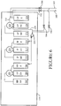
- FIG. 6 illustrates another alternate embodiment.
- the supply line 160 is connected to both the feed water line 229 and the feed line 225.
- the return line 165 is also connected to the feed water line 229 and the feed line 225 at positions located immediately downstream from where the supply line 160 is connected.
- Valves 192 and 194 are used to selectively couple the supply line 160 and return line 165 to the feed line 225.
- valves 196 and 198 are used to selectively couple the supply line 160 and the return line 165 to the feed water line 229.
- plant operators can draw fluid from either the feed line 225 or the feed water line 229, as they see fit.
- fluid used to heat the inlet-air could be drawn from both the feed line 225 and the feed water line 229 simultaneously.
- the valves 192, 194, 196 and 198 could be used to vary the relative amounts of fluids being drawn from the feed line 225 and feed water line 229.
Landscapes
- Engineering & Computer Science (AREA)
- Chemical & Material Sciences (AREA)
- Combustion & Propulsion (AREA)
- Mechanical Engineering (AREA)
- General Engineering & Computer Science (AREA)
- Engine Equipment That Uses Special Cycles (AREA)
Description
- The invention relates to systems and methods for improving the efficiency of a power generating facility that utilizes a turbine.
- Turbomachines, such as gas turbines, aero-derivatives, or the like, commonly operate in a combined-cycle and/or cogeneration mode. In combined-cycle operation, a gas turbine is connected to a generator that produces electricity. A heat recovery steam generator (HRSG) receives at least a portion of the exhaust gas produced by the gas turbine, and the HRSG uses the heat energy in the exhaust gas to generate steam. The steam produced by the HRSG flows to a steam turbine connected to another generator which produces additional electricity. In a co-generation operation, a portion of the steam generated by the HRSG is sent to a separate process requiring the steam.
- Combined-cycle and cogeneration plants are rated to generate the maximum amount of energy (mechanical, electrical, etc) at minimum fuel consumption while operating at base load. However, if possible, it is desirable to improve the efficiency of the system when operating at base load.
- Base load operations, although desired by operators, is not always feasible. There may not be a demand in the energy market (electrical grid, or the like) for all of the energy generated at base load. In these situations, the power plant either must shutdown or operate at part load, where less than the maximum amount of energy is generated. When a turbine in such a power generation facility is operating at part load, the overall efficiency of the system is typically lower than when the turbine is operating at base load. Thus, there is a need to improve the efficiency of the system when operating under part load conditions.
- Gas turbines are typically required to maintain emissions compliance while generating power. A gas turbine operating at part load may not maintain emissions compliance if it is running below a particular load point. The "turndown range" is the loading range where the gas turbine maintains emissions compliance. A broad turndown range allows operators to maintain emissions compliance, minimize fuel consumption, and avoid the thermal transients associated with shutting down the power plant under a broad range of electricity output conditions. Thus, it is desirable to make the turndown range as broad as possible.
- When it is desirable to make changes to an existing power plant to increase efficiency, any retrofit solutions should preferably minimize modifications to existing equipment. This is desirable both from a cost perspective, and also to avoid negatively impacting plant operability. Further, any retrofit changes should not increase operation or maintenance costs, otherwise the retrofit changes may not be economically worthwhile.
- For all the foregoing reasons, there is a need for a system for improving the efficiency of a power generation facility that is operating at either base load or part load conditions. There is also a need for a system for improving the turndown range
of gas turbines. However, any changes made to achieve a higher efficiency or to increase turndown range should not significantly impact other plant operations or maintenance requirements. Otherwise the improvements in efficiency and/or turndown range may be outweighed by higher operating or maintenance costs, or reduced efficiency during other operating conditions. -
EP 2105598 A2 discloses arrangements for pre-heating air in a combined cycle power plant using heat extracted from turbo-machine exhaust gas.US 2010/0031660 A1 discloses arrangements for pre-heating fuel in a combined cycle power plant using heat extracted from turbo-machine exhaust gas. - In one aspect, the invention can be embodied in a system for improving the efficiency of a power generation facility. The system includes a turbine comprising a compressor which receives inlet-air, a combustion system and a turbine section, wherein the turbine produces an exhaust-gas. The system also includes a heat recovery steam generator (HRSG) which receives a portion of the exhaust-gas and produces steam. The system also includes a preheater that obtains heat energy from the HRSG and that uses that heat energy to improve the efficiency of the power generation facility, wherein the heat energy obtained from the HRSG is obtained from a fluid drawn from a predetermined point within the HRSG, and wherein after heat energy has been extracted from the fluid, the fluid is returned to the HRSG at a location immediately downstream from the point at which it was initially drawn from the HRSG.
- In another aspect, the invention can be embodied in a method of improving the efficiency of a power generation facility that includes a turbine having a compressor which receives inlet-air, a combustion system and a turbine section, the turbine producing an exhaust-gas that is at least partially provided to a heat recovery steam generator (HRSG). The method includes drawing fluid from a predetermined point within the HRSG, obtaining heat energy from the fluid, using the obtained heat energy to improve the efficiency of the power generation facility, and returning the fluid to a location that is immediately downstream from the point at which it was drawn from the HRSG after heat energy has been obtained from the fluid.
-
-
FIG. 1 is a diagram of elements of a first combined cycle power plant; -
FIG. 2 is a diagram of elements of a second combined cycle power plant; -
FIG. 3 is a diagram of elements of a third combined cycle power plant; -
FIG. 4 is a diagram of elements of a first embodiment of a heat recovery steam generator that could be used in a combined cycle power plant; -
FIG. 5 is a diagram of elements of a second embodiment of a heat recovery steam generator that could be used in a combined cycle power plant; and -
FIG. 6 is a diagram of elements of a third embodiment of a heat recovery steam generator that could be used in a combined cycle power plant. - The following detailed description of preferred embodiments refers to the accompanying drawings, which partly illustrate specific embodiments of the invention. Other embodiments having different structures and operations do not depart from the scope of the present invention, which is defined by the appended claims.
- The present invention may be applied to a wide variety of turbomachines including, but not limited to, gas turbines, aero-derivative combustion turbines, and the like. An embodiment of the present invention takes the form of an application and process that extracts heat energy from an exhaust-gas of a turbine and that uses that heat energy to increase the efficiency of the turbomachine when the turbomachine is operating at part load conditions. The extracted heat energy could be used to heat the air entering a turbomachine, to heat fuel that is burned in the turbomachine, or for other purposes. An embodiment of the present invention has the beneficial effect of improving the efficiency of a power generation facility when the facility is operating under part load conditions.
-
FIG. 1 illustrates a system designed for combined-cycle operations. The system includes a gas turbine that includes anaxial flow compressor 120 having ashaft 125. Inlet-air 132 enters thecompressor 120 where it is compressed and then discharged to acombustion system 135. In thecombustion system 135, the compressed air is mixed with a fuel such as natural gas, and the air-fuel mixture is burned to provide high-energy combustion gases which drive aturbine section 145. In theturbine section 145, the energy of the combustion gases is converted into work, some of which is used to drive thecompressor 120 through theshaft 125. The turbine also drives agenerator 170 that produces electricity. - A portion of the exhaust gases produced by the turbine is routed to a heat recovery steam generator (HRSG) 110. The HRSG uses heat energy in the exhaust gases from the turbine to produce steam which is routed to a
steam turbine 147 through asteam line 166. Thesteam turbine 147 is connected to agenerator 172 that also produces electricity. The steam exiting thesteam turbine 147 is condensed in a surface condenser and is pumped by acondensate pump 167 back to the HRSG via areturn line 169. - The present invention can improve the efficiency of the system when the turbine is operating at part load conditions by heating the inlet-air flowing into the
compressor 120. Generally, the output (electrical, mechanical, or the like) of a gas turbine is governed by the amount of mass-flow entering thecompressor 120. The mass-flow may be considered the product of the density and the volume-flow of the inlet-air 132 entering thecompressor 120. The amount of volume-flow entering thecompressor 120 may vary based on the compressor inlet temperature conditions and the angle of variable Inlet Guide Vanes (IGV), if present, on the gas turbine. The IGV angle may determine the flow area at the inlet of thecompressor 120. The IGV angle may be reduced to a minimum angle, limiting the amount of turndown. At the minimum IGV angle, a corresponding minimum volume-flow is drawn into thecompressor 120. - In systems and methods embodying the present invention, heating of the inlet-
air 132 decreases the density of the air flowing into thecompressor 120. As discussed, the output of the gas turbine may be determined by the mass-flow entering the gas turbine. At a given load point, the mass-flow may remain almost constant, but the volume-flow entering thecompressor 120 increases due to the decrease in the density of theinlet air 132. Thus, heating of the inlet air opens the inlet guide vane angle to maintain constant mass-flow, and as a result, the efficiencies of the compressor and turbine are increased. Heating of the inlet air can also allow the turbine to operate at a lower setting than would be possible without inlet heating, which increases the turndown range. - The plant illustrated in
FIG. 1 includes apreheater 155 that is installed upstream of thecompressor 120. Thepreheater 155 may be a heat exchanger, or the like. Thepreheater 155 receivesambient air 130 and produces heated inlet-air 132 that flows into thecompressor 120 of the turbine. - Of course, during base load operations no preheating would be required. Under those conditions, the
ambient air 130 would simply flow through thepreheater 155 and into thecompressor 120. However, when it is desirable to operate at less than base load, thepreheater 155 is used to preheat the inlet-air 132 to achieve the benefits described above. Generally, the temperature of the unheated inlet-air 130 may be determined by the ambient conditions or the outlet temperature of any air conditioning system (not illustrated) located upstream of theair preheater 155. An embodiment of the present invention may increase the temperature of theambient air 130 to any temperature allowed for by thepreheater 155. However, the increase in temperature of theambient air 130 may be limited by at least one of several factors. For instance, the amount by which the ambient air can be heated may be limited by the geometrical limitations of theair preheater 155, a temperature that may violate a thermal, operational, or mechanical limitation, or the amount of heat energy available to thepreheater 155 for heating theambient air 130. - In the system illustrated in
FIG. 1 , thepreheater 155 receives a flow of fluid from theHRSG 110 through asupply line 160. The fluid travels through the preheater and is then returned to theHRSG 110 through areturn line 165. Apump 159 is used to cause the fluid to flow from theHRSG 110 to thepreheater 155 and back to theHRSG 110. Thepump 159 could be a variable speed pump or a constant speed pump. Acontrol valve 157 can be used to control the flow of fluid to the preheater. By varying the amount of fluid flowing to thepreheater 155, one can control the degree to which the inlet air is heated before it enters the compressor. If the pump is a constant speed pump, thecontrol valve 157 could be a three way control valve that is also connected to a bypass circuit. - The source of the fluid flowing through the
supply line 160, thepreheater 155 and thereturn line 165 is discussed in detail below. However, the temperature of the fluid is higher than the temperature of theambient air 130. As a result, circulation of the fluid through thepreheater 155 raises the temperature of theambient air 130 to generate heated inlet-air 132 that is supplied to thecompressor 120. -
FIG. 2 illustrates a second plant which includes a preheater that heats fuel being burned in the turbine. Here, apreheater 155 receives fuel from afuel supply line 131 and a flow of fluid from theHRSG 110 through asupply line 160. The fluid circulates through the preheater and is then returned to theHRSG 110 through areturn line 165. Apump 159 is used to cause the fluid to flow from theHRSG 110 to thepreheater 155 and back to theHRSG 110. The pump could be a constant speed pump or a variable speed pump. Acontrol valve 157 may be used to control the amount of fluid being routed to thepreheater 155, and thus the amount of preheating that occurs. The control valve could be a three way valve that is also coupled to a bypass circuit. - The preheater utilizes heat energy from the fluid flowing through the
supply line 160 to preheat the fuel being supplied to the turbine. The preheating of the fuel can increase the efficiency of the turbine, and thus the efficiency of the overall system. -
FIG. 3 illustrates another plant. Here, fluid drawn from theHRSG 110 and flowing through thesupply line 160 is routed through a heat exchanger 180. The fluid then exits the heat exchanger 180 and is returned to theHRSG 110 by thereturn line 165. - A heat transfer medium flows from the heat exchanger 180 through a
supply line 188 into thepreheater 155. The heat transfer medium is circulated from thepreheater 155 back to the heat exchanger 180 by acirculation pump 184. A three-way control valve 182 is used to control the flow of the heat transfer medium. - When the fluid from the
HRSG 110 is circulating through the heat exchanger 180, and the heat transfer medium is circulating between the heat exchanger 180 and thepreheater 155, heat energy in the fluid drawn from the HRSG is transferred to the heat transfer medium in the heat exchanger 180. This heat energy is then transferred to theambient air 130 to create the heated inlet-air 132 in thepreheater 155. With a system as illustrated inFIG. 3 , the fluid drawn from theHRSG 155 can be kept completely separate from the heat transfer medium flowing through thepreheater 155. This allows a separate fluid with a lower freezing point to be used as the heat transfer medium, which provides system freeze protection and improves the system operating range and availability. - The heat transfer medium can be any fluid, liquid or gas. For example, the heat transfer medium could be water, ethylene glycol, or mixtures of those fluids. Any other suitable fluid, liquid or gas could also be used.
- The amount of heat that is transferred to the inlet air can be controlled by controlling a flow rate of the fluid from the HRSG through the heat exchanger 180. The flow rate could be controlled via a variable speed pump. Alternatively, if the pump is a constant speed pump, the control valve could be a three-
way control valve 157 that allows a selected portion of the fluid to bypass the heat exchanger 180 via a bypass circuit. - The amount of heat transferred to the inlet air can also be controlled by controlling the flow rate of the heat exchange medium through the heat exchanger 180 and
preheater 155. Here again, thepump 184 could be a variable speed pump to provide control over the flow rate. Alternatively, thepump 184 could be a constant speed pump, and a three-way control valve 182 coupled to a bypass circuit could be used to control the flow rate of the heat exchange medium. -
FIG. 3 also illustrates that an alternate orauxiliary heat exchanger 181 may also be coupled to the lines carrying the heat transfer medium. The auxiliary heat exchanger would utilize some other source of heat, such as a plant auxiliary cooling system, to heat the heat transfer medium. That heat energy would then be used to pre-heat the inlet air flowing into thecompressor 120. Theauxiliary heat exchanger 181 could be used alone, or in conjunction with the heat exchanger 180 to heat the heat transfer medium. - The systems illustrated in
FIGs. 1 and2 could also make use of the same type of auxiliary heat exchanger. However, the auxiliary heat exchanger would be coupled to theinlet line 160 passing from theHRSG 110 to thepreheater 155. -
Figure 4 illustrates portions of aHRSG 110 showing aspects of the invention that could be used in the systems illustrated inFIGS. 1-3 . TheHRSG 110 includes high pressure, intermediate pressure and low pressure stages. - The high pressure stage includes a
high pressure superheater 202, ahigh pressure evaporator 204 that generates steam collected in ahigh pressure drum 208, and ahigh pressure economizer 206 coupled to thehigh pressure drum 208. - Likewise, the intermediate pressure stage includes an
intermediate pressure superheater 212, anintermediate pressure evaporator 214 that generates steam collected in anintermediate pressure drum 218, and anintermediate pressure economizer 216 coupled to theintermediate pressure drum 218. - The low pressure stage includes a
low pressure superheater 222, alow pressure evaporator 224 that generates steam collected in alow pressure drum 228, and alow pressure economizer 226 coupled to thelow pressure drum 228 through afeed line 225. Also, condensate from thelow pressure drum 228 passes along a boilerfeed water line 229 to afeed water pump 130. Thefeed water pump 130 sends the condensate to theintermediate pressure economizer 216 and thehigh pressure economizer 206. - Although the above description applies to a typical HRSG, an individual HRSG may have fewer than all described components, or many additional components. The above description is only illustrative to help explain the thermal integration of the heat energy between the
HRSG 110 and thepreheater 155 or heat exchanger 180. - In the embodiment illustrated in
FIG. 4 , thefluid supply line 160 that runs to thepreheater 155 in the system illustrated inFIGs. 1 and2 or the heat exchanger 180 in the system illustrated inFIG. 3 is connected to thefeed water line 229 between thelow pressure drum 228 and thefeed water pump 130. Also, thereturn line 165 that returns fluid to theHRSG 110 is connected to the samefeed water line 229 immediately downstream from the position where thesupply line 160 is connected. - In an alternate embodiment illustrated in
FIG. 5 , thesupply line 160 is connected to thefeed line 225 between thelow pressure economizer 226 and thelow pressure drum 228. Thereturn line 165 is also connected to thefeed line 225 immediately downstream from the position where thesupply line 160 is connected. - Fluid drawn from either the
feed water line 229 or thefeed line 225 of theHRSG 110 has a sufficiently high temperature to be used to heatambient air 130 to produceheated inlet air 132 supplied to thecompressor 120. Also, using fluid drawn from either of these two lines has other advantages. - The HRSG in an existing power plant will have been designed to operate within a particular environment. The operating temperatures of the steam and the fluids, the flow rates, the water levels in the high, intermediate and low pressure drums and various other factors are part of the design of the HRSG. If an inlet-air preheating system as described above is retrofitted into an existing power plant, removing heat energy from the HRSG for use in a preheater may negatively impact the operation and efficiency of the HRSG itself, as well as any components that utilize the steam produced by the HRSG, such as the
steam turbine 172 illustrated inFIGs. 1-3 . - Removing heat energy from the fluids running through the low pressure portions of the HRSG is likely to minimize the performance penalty to the steam cycle, and thus any components that reply upon the steam produced by the HRSG, as compared to extracting heat from fluids drawn from the intermediate or high pressure portions of the HRSG. This is also likely to minimize the impact to operation of the HRSG. Nevertheless, under certain situations, such as where a higher temperature fluid is required, it may make sense to extract heat from fluids drawn from the intermediate or high pressure portions of the HRSG.
- One can also minimize the impact to the HRSG by returning a fluid used for heat energy back immediately downstream of the location in the HRSG from which it was extracted. Thus, in the embodiment illustrated in
FIG. 4 , thefluid return line 165 is connected to thefeed water line 229 at a location immediately downstream of the point at which thesupply line 160 is connected. Likewise, in the embodiment illustrated inFIG. 5 , thefluid return line 165 is connected to thefeed line 225 at a location immediately downstream of the point at which thesupply line 160 is connected. By connecting the supply and return lines in this fashion, one can ensure that there is minimal impact on the original designed water flow rates for the HRSG. - Also, because the fluid is being drawn from the low pressure portion of the HRSG, the physical strength and safety requirements for the
supply line 160, thereturn line 165, thecirculation pump 159 and thecontrol valve 157 can be kept to a minimum. If fluid was drawn from the intermediate pressure or high pressure portions of the HRSG, these elements would need to be stronger, and therefore would be more expensive. In addition, routing an intermediate or high pressure fluid back to thepreheater 155 or to a heat exchanger 180 would involve additional safety risks to the plant and plant operating personnel that are not present when a low pressure fluid is used. -
FIG. 6 illustrates another alternate embodiment. In this embodiment, thesupply line 160 is connected to both thefeed water line 229 and thefeed line 225. Likewise, thereturn line 165 is also connected to thefeed water line 229 and thefeed line 225 at positions located immediately downstream from where thesupply line 160 is connected.Valves supply line 160 and returnline 165 to thefeed line 225. Also,valves supply line 160 and thereturn line 165 to thefeed water line 229. Thus, in an embodiment as illustrated inFIG. 6 , plant operators can draw fluid from either thefeed line 225 or thefeed water line 229, as they see fit. Also, if desired, fluid used to heat the inlet-air could be drawn from both thefeed line 225 and thefeed water line 229 simultaneously. Further, thevalves feed line 225 and feedwater line 229.
Claims (13)
- A system for improving the efficiency of a power generation facility, comprising:a turbine comprising a compressor (120) which receives inlet-air (132), a combustion system (135) and a turbine section (145), wherein the turbine produces an exhaust-gas;a heat recovery steam generator (HRSG) (110) which receives a portion (150) of the exhaust-gas and produces steam; anda preheater (155) that obtains heat energy from the HRSG (110) and that is configured to use that heat energy to improve the efficiency of the power generation facility, wherein the heat energy obtained from the HRSG (110) is obtained from a fluid drawn via a supply line (160) from a predetermined point within the HRSG (110), and wherein after heat energy has been extracted from the fluid, the fluid is returned via a return line (165) to the HRSG (110) at a location immediately downstream from the point at which it was initially drawn from the HRSG (110).
- The system of claim 1, wherein the predetermined point is a feed water line (229) exiting a drum (228) of the HRSG (110).
- The system of claim 1, wherein the predetermined point is a feed line (229) connecting an economizer (206) of the HRSG to a drum (228) of the HRSG (110).
- The system of any preceding claim, wherein the system is configured such that the flow rate of the fluid drawn (160) from the predetermined point within the HRSG (110) is substantially the same as the flow rate of the fluid returned (165) immediately downstream from the predetermined point within the HRSG (110).
- The system of any preceding claim, wherein the preheater (155) is configured to use the heat energy from the HRSG (110) to heat the inlet-air (132) before the inlet-air flows into the compressor (120).
- The system of any preceding claim, wherein the preheater (155) is configured to use the heat energy from the HRSG (110) to preheat fuel (131) that is burned in the combustion system (135) of the turbine.
- The system of claim 1, further comprising:a heat exchanger (180) that receives the fluid drawn via the supply line (160) from the predetermined point within the HRSG (110); anda fluid circuit (188) that circulates a heat transfer medium between the heat exchanger (180) and the preheater (155), wherein heat obtained from the fluid drawn via the supply line (160) from the HRSG (110) is transferred to the heat transfer medium in the heat exchanger (180).
- The system of claim 7, wherein the fluid drawn via the supply line (160) from the HRSG (110) passes through the heat exchanger (180) and is returned immediately downstream from the predetermined point within the HRSG (110).
- The system of claim 1, wherein the fluid drawn via the supply line (160) from the predetermined point within the HRSG (110) is drawn from multiple points within the HRSG (110), and wherein after heat energy has been extracted from the fluid, the fluid is returned to the HRSG (110) immediately downstream from the same predetermined points.
- A method of improving the efficiency of a power generation facility that includes a turbine having a compressor (120) which receives inlet-air (132), a combustion system (135) and a turbine section (145), the turbine producing an exhaust-gas that is at least partially provided (150) to a heat recovery steam generator (HRSG) (110), the method comprising:drawing fluid (160) from a predetermined point within the HRSG (110);obtaining heat energy (155,180) from the fluid;using the obtained heat energy to improve the efficiency of the power generation facility; andreturning the fluid (165) to a location that is immediately downstream from the point at which it was drawn from the HRSG (110) after heat energy has been obtained from the fluid.
- The method of claim 10, wherein the heat energy is used to heat the inlet-air (132) before the inlet-air flows into the compressor (120).
- The method of claim 10 or claim 11, wherein the heat energy is used to preheat fuel (131) that is burned in the combustion system (135) of the turbine.
- The method of any of claims 10 to 12, wherein the fluid is drawn from and returned to a feed water line (229) exiting a drum (228) of the HRSG (110).
Applications Claiming Priority (1)
| Application Number | Priority Date | Filing Date | Title |
|---|---|---|---|
| US13/159,657 US8505309B2 (en) | 2011-06-14 | 2011-06-14 | Systems and methods for improving the efficiency of a combined cycle power plant |
Publications (3)
| Publication Number | Publication Date |
|---|---|
| EP2535542A2 EP2535542A2 (en) | 2012-12-19 |
| EP2535542A3 EP2535542A3 (en) | 2018-03-07 |
| EP2535542B1 true EP2535542B1 (en) | 2019-07-31 |
Family
ID=46465019
Family Applications (1)
| Application Number | Title | Priority Date | Filing Date |
|---|---|---|---|
| EP12171879.5A Active EP2535542B1 (en) | 2011-06-14 | 2012-06-13 | Systems and methods for improving the efficiency of a combined cycle power plant |
Country Status (3)
| Country | Link |
|---|---|
| US (1) | US8505309B2 (en) |
| EP (1) | EP2535542B1 (en) |
| CN (1) | CN102828830B (en) |
Families Citing this family (21)
| Publication number | Priority date | Publication date | Assignee | Title |
|---|---|---|---|---|
| JP2014139424A (en) * | 2013-01-21 | 2014-07-31 | Mitsubishi Heavy Ind Ltd | Power generation system |
| FI127597B (en) * | 2013-03-05 | 2018-09-28 | Loeytty Ari Veli Olavi | Method and apparatus for achieving high efficiency in the open gas turbine (combi) process |
| ITMI20130368A1 (en) * | 2013-03-12 | 2014-09-13 | Ansaldo Energia Spa | COMBINED CYCLE PLANT FOR THE PRODUCTION OF ELECTRICITY WITH CONTROL OF INLET AIR TEMPERATURE AND METHOD OF CONTROL OF A COMBINED CYCLE SYSTEM FOR THE PRODUCTION OF ELECTRICITY |
| EP2789829A1 (en) * | 2013-04-12 | 2014-10-15 | Siemens Aktiengesellschaft | Method for reducing the CO emissions of a gas turbine and gas turbine |
| EP2824293A1 (en) * | 2013-07-08 | 2015-01-14 | Alstom Technology Ltd | Power plant with integrated fuel gas preheating |
| CA2924710C (en) | 2013-09-19 | 2018-03-27 | Siemens Aktiengesellschaft | Combined cycle gas turbine plant having a waste heat steam generator |
| JP6407079B2 (en) * | 2015-03-25 | 2018-10-17 | 三菱日立パワーシステムズ株式会社 | Gas turbine system using high-humidity air and its exhaust gas treatment system |
| CN104912669B (en) * | 2015-06-25 | 2017-06-06 | 上海电气燃气轮机有限公司 | The air inlet air conditioning system and its application method of Combined cycle gas-steam turbine power plant |
| CN105484815B (en) * | 2015-12-31 | 2018-10-23 | 中国能源建设集团广东省电力设计研究院有限公司 | Combustion and steam association system and its progress control method |
| CN105464808B (en) * | 2015-12-31 | 2018-07-20 | 中国能源建设集团广东省电力设计研究院有限公司 | Combustion and steam association system and its progress control method |
| US10253683B2 (en) | 2016-08-10 | 2019-04-09 | Garrett Transportation I Inc. | Variable-nozzle turbine with means for radial locating of variable-nozzle cartridge |
| US10830105B2 (en) * | 2016-12-12 | 2020-11-10 | General Electric Company | System and method for improving output and heat rate for a liquid natural gas combined cycle power plant |
| CN106762140A (en) * | 2016-12-19 | 2017-05-31 | 南方科技大学 | Distributed power generation device of aeroderivative fuel machine |
| US10337357B2 (en) | 2017-01-31 | 2019-07-02 | General Electric Company | Steam turbine preheating system with a steam generator |
| US10174639B2 (en) * | 2017-01-31 | 2019-01-08 | General Electric Company | Steam turbine preheating system |
| US10900418B2 (en) * | 2017-09-28 | 2021-01-26 | General Electric Company | Fuel preheating system for a combustion turbine engine |
| WO2019223985A1 (en) * | 2018-05-22 | 2019-11-28 | Siemens Aktiengesellschaft | Extended gas turbine process having an expander |
| JP7349266B2 (en) * | 2019-05-31 | 2023-09-22 | 三菱重工業株式会社 | Gas turbine and its control method and combined cycle plant |
| FR3117168B1 (en) | 2020-12-03 | 2023-08-25 | Total Se | Process for producing electrical and/or mechanical energy for a consumer system and associated production system |
| US11448129B2 (en) * | 2020-12-08 | 2022-09-20 | General Electric Company | Inlet air heating system for a gas turbine system |
| US11300011B1 (en) * | 2021-04-20 | 2022-04-12 | General Electric Company | Gas turbine heat recovery system and method |
Family Cites Families (20)
| Publication number | Priority date | Publication date | Assignee | Title |
|---|---|---|---|---|
| US3150487A (en) * | 1963-04-08 | 1964-09-29 | Gen Electric | Steam turbine-gas turbine power plant |
| US4267692A (en) * | 1979-05-07 | 1981-05-19 | Hydragon Corporation | Combined gas turbine-rankine turbine power plant |
| EP0683847B1 (en) * | 1993-12-10 | 1998-08-12 | Cabot Corporation | An improved liquefied natural gas fueled combined cycle power plant |
| US5491971A (en) * | 1993-12-23 | 1996-02-20 | General Electric Co. | Closed circuit air cooled gas turbine combined cycle |
| JP3681434B2 (en) * | 1995-04-25 | 2005-08-10 | 重昭 木村 | Cogeneration system and combined cycle power generation system |
| DE19745272C2 (en) * | 1997-10-15 | 1999-08-12 | Siemens Ag | Gas and steam turbine plant and method for operating such a plant |
| US6145295A (en) * | 1998-11-23 | 2000-11-14 | Siemens Westinghouse Power Corporation | Combined cycle power plant having improved cooling and method of operation thereof |
| AU4698600A (en) | 1999-05-05 | 2000-11-17 | Ut-Battelle, Llc | Method and apparatus for combinatorial chemistry |
| US7644573B2 (en) | 2006-04-18 | 2010-01-12 | General Electric Company | Gas turbine inlet conditioning system and method |
| US7963095B2 (en) | 2006-06-21 | 2011-06-21 | General Electric Company | Inlet air conditioning system |
| US20080098891A1 (en) | 2006-10-25 | 2008-05-01 | General Electric Company | Turbine inlet air treatment apparatus |
| US9043118B2 (en) | 2007-04-02 | 2015-05-26 | General Electric Company | Methods and systems for model-based control of gas turbines |
| US20090235634A1 (en) | 2008-03-24 | 2009-09-24 | General Electric Company | System for extending the turndown range of a turbomachine |
| US8205451B2 (en) * | 2008-08-05 | 2012-06-26 | General Electric Company | System and assemblies for pre-heating fuel in a combined cycle power plant |
| US8483929B2 (en) | 2008-11-21 | 2013-07-09 | General Electric Company | Method of controlling an air preheating system of a gas turbine |
| US8468830B2 (en) | 2008-12-11 | 2013-06-25 | General Electric Company | Inlet air heating and cooling system |
| US20100146978A1 (en) | 2008-12-11 | 2010-06-17 | General Electric Company | Gas Turbine Base Load Control by Chilling Modulation |
| US9470149B2 (en) | 2008-12-11 | 2016-10-18 | General Electric Company | Turbine inlet air heat pump-type system |
| US8356466B2 (en) | 2008-12-11 | 2013-01-22 | General Electric Company | Low grade heat recovery system for turbine air inlet |
| EP2256316A1 (en) * | 2009-05-28 | 2010-12-01 | Siemens Aktiengesellschaft | Intake air tempering device and a method for operating same |
-
2011
- 2011-06-14 US US13/159,657 patent/US8505309B2/en active Active
-
2012
- 2012-06-13 EP EP12171879.5A patent/EP2535542B1/en active Active
- 2012-06-14 CN CN201210195721.3A patent/CN102828830B/en active Active
Non-Patent Citations (1)
| Title |
|---|
| None * |
Also Published As
| Publication number | Publication date |
|---|---|
| US20120317988A1 (en) | 2012-12-20 |
| CN102828830A (en) | 2012-12-19 |
| EP2535542A3 (en) | 2018-03-07 |
| US8505309B2 (en) | 2013-08-13 |
| EP2535542A2 (en) | 2012-12-19 |
| CN102828830B (en) | 2016-08-17 |
Similar Documents
| Publication | Publication Date | Title |
|---|---|---|
| US8505309B2 (en) | Systems and methods for improving the efficiency of a combined cycle power plant | |
| JP5357588B2 (en) | System for extending turbomachine turndown range | |
| US20110247335A1 (en) | Waste heat steam generator and method for improved operation of a waste heat steam generator | |
| US10337357B2 (en) | Steam turbine preheating system with a steam generator | |
| EP2662536A2 (en) | Gas Turbine Compressor Water Wash System | |
| US10900418B2 (en) | Fuel preheating system for a combustion turbine engine | |
| EP2208862B1 (en) | Compressor clearance control system and method for providing clearance control | |
| CN104246151B (en) | For the method that frequency remains on combustion gas and steam turbine | |
| JP2001214759A (en) | Gas turbine combined cycle | |
| JP2004162601A (en) | Steam turbine output estimating device in dual fuel type uniaxial combined plant | |
| US10287922B2 (en) | Steam turbine plant, combined cycle plant provided with same, and method of operating steam turbine plant | |
| JP6870970B2 (en) | Steam generation system by turbine extraction | |
| US11879365B2 (en) | Steam turbine plant and operation method, combined cycle plant and operation method | |
| JPH1150812A (en) | Exhaust reburning combined cycle power plant | |
| US9404395B2 (en) | Selective pressure kettle boiler for rotor air cooling applications | |
| JP2022161839A (en) | Combined cycle power plant having serial heat exchangers | |
| US20150121871A1 (en) | Forced cooling in steam turbine plants | |
| US20140069078A1 (en) | Combined Cycle System with a Water Turbine | |
| EP2752566B1 (en) | Gas turbine cooling system, and gas turbine cooling method | |
| JP5812873B2 (en) | Combined cycle power plant | |
| US11859548B2 (en) | Gas turbine and control method thereof, and combined cycle plant | |
| JP3389019B2 (en) | Steam cooled gas turbine | |
| EP3318733B1 (en) | Feedwater bypass system for a desuperheater | |
| JP4209060B2 (en) | Steam cooling rapid start system | |
| JPH1182060A (en) | Hydrogen combustion turbine plant |
Legal Events
| Date | Code | Title | Description |
|---|---|---|---|
| PUAI | Public reference made under article 153(3) epc to a published international application that has entered the european phase |
Free format text: ORIGINAL CODE: 0009012 |
|
| AK | Designated contracting states |
Kind code of ref document: A2 Designated state(s): AL AT BE BG CH CY CZ DE DK EE ES FI FR GB GR HR HU IE IS IT LI LT LU LV MC MK MT NL NO PL PT RO RS SE SI SK SM TR |
|
| AX | Request for extension of the european patent |
Extension state: BA ME |
|
| PUAL | Search report despatched |
Free format text: ORIGINAL CODE: 0009013 |
|
| AK | Designated contracting states |
Kind code of ref document: A3 Designated state(s): AL AT BE BG CH CY CZ DE DK EE ES FI FR GB GR HR HU IE IS IT LI LT LU LV MC MK MT NL NO PL PT RO RS SE SI SK SM TR |
|
| AX | Request for extension of the european patent |
Extension state: BA ME |
|
| RIC1 | Information provided on ipc code assigned before grant |
Ipc: F02C 7/224 20060101ALI20180130BHEP Ipc: F02C 7/08 20060101AFI20180130BHEP Ipc: F02C 6/18 20060101ALI20180130BHEP |
|
| STAA | Information on the status of an ep patent application or granted ep patent |
Free format text: STATUS: REQUEST FOR EXAMINATION WAS MADE |
|
| 17P | Request for examination filed |
Effective date: 20180907 |
|
| RBV | Designated contracting states (corrected) |
Designated state(s): AL AT BE BG CH CY CZ DE DK EE ES FI FR GB GR HR HU IE IS IT LI LT LU LV MC MK MT NL NO PL PT RO RS SE SI SK SM TR |
|
| GRAP | Despatch of communication of intention to grant a patent |
Free format text: ORIGINAL CODE: EPIDOSNIGR1 |
|
| STAA | Information on the status of an ep patent application or granted ep patent |
Free format text: STATUS: GRANT OF PATENT IS INTENDED |
|
| INTG | Intention to grant announced |
Effective date: 20190109 |
|
| GRAS | Grant fee paid |
Free format text: ORIGINAL CODE: EPIDOSNIGR3 |
|
| GRAA | (expected) grant |
Free format text: ORIGINAL CODE: 0009210 |
|
| STAA | Information on the status of an ep patent application or granted ep patent |
Free format text: STATUS: THE PATENT HAS BEEN GRANTED |
|
| AK | Designated contracting states |
Kind code of ref document: B1 Designated state(s): AL AT BE BG CH CY CZ DE DK EE ES FI FR GB GR HR HU IE IS IT LI LT LU LV MC MK MT NL NO PL PT RO RS SE SI SK SM TR |
|
| REG | Reference to a national code |
Ref country code: CH Ref legal event code: EP Ref country code: GB Ref legal event code: FG4D |
|
| REG | Reference to a national code |
Ref country code: DE Ref legal event code: R096 Ref document number: 602012062403 Country of ref document: DE |
|
| REG | Reference to a national code |
Ref country code: AT Ref legal event code: REF Ref document number: 1161142 Country of ref document: AT Kind code of ref document: T Effective date: 20190815 |
|
| REG | Reference to a national code |
Ref country code: IE Ref legal event code: FG4D |
|
| REG | Reference to a national code |
Ref country code: NL Ref legal event code: MP Effective date: 20190731 |
|
| REG | Reference to a national code |
Ref country code: LT Ref legal event code: MG4D |
|
| REG | Reference to a national code |
Ref country code: AT Ref legal event code: MK05 Ref document number: 1161142 Country of ref document: AT Kind code of ref document: T Effective date: 20190731 |
|
| PG25 | Lapsed in a contracting state [announced via postgrant information from national office to epo] |
Ref country code: PT Free format text: LAPSE BECAUSE OF FAILURE TO SUBMIT A TRANSLATION OF THE DESCRIPTION OR TO PAY THE FEE WITHIN THE PRESCRIBED TIME-LIMIT Effective date: 20191202 Ref country code: FI Free format text: LAPSE BECAUSE OF FAILURE TO SUBMIT A TRANSLATION OF THE DESCRIPTION OR TO PAY THE FEE WITHIN THE PRESCRIBED TIME-LIMIT Effective date: 20190731 Ref country code: LT Free format text: LAPSE BECAUSE OF FAILURE TO SUBMIT A TRANSLATION OF THE DESCRIPTION OR TO PAY THE FEE WITHIN THE PRESCRIBED TIME-LIMIT Effective date: 20190731 Ref country code: HR Free format text: LAPSE BECAUSE OF FAILURE TO SUBMIT A TRANSLATION OF THE DESCRIPTION OR TO PAY THE FEE WITHIN THE PRESCRIBED TIME-LIMIT Effective date: 20190731 Ref country code: SE Free format text: LAPSE BECAUSE OF FAILURE TO SUBMIT A TRANSLATION OF THE DESCRIPTION OR TO PAY THE FEE WITHIN THE PRESCRIBED TIME-LIMIT Effective date: 20190731 Ref country code: AT Free format text: LAPSE BECAUSE OF FAILURE TO SUBMIT A TRANSLATION OF THE DESCRIPTION OR TO PAY THE FEE WITHIN THE PRESCRIBED TIME-LIMIT Effective date: 20190731 Ref country code: NL Free format text: LAPSE BECAUSE OF FAILURE TO SUBMIT A TRANSLATION OF THE DESCRIPTION OR TO PAY THE FEE WITHIN THE PRESCRIBED TIME-LIMIT Effective date: 20190731 Ref country code: BG Free format text: LAPSE BECAUSE OF FAILURE TO SUBMIT A TRANSLATION OF THE DESCRIPTION OR TO PAY THE FEE WITHIN THE PRESCRIBED TIME-LIMIT Effective date: 20191031 Ref country code: NO Free format text: LAPSE BECAUSE OF FAILURE TO SUBMIT A TRANSLATION OF THE DESCRIPTION OR TO PAY THE FEE WITHIN THE PRESCRIBED TIME-LIMIT Effective date: 20191031 |
|
| PG25 | Lapsed in a contracting state [announced via postgrant information from national office to epo] |
Ref country code: IS Free format text: LAPSE BECAUSE OF FAILURE TO SUBMIT A TRANSLATION OF THE DESCRIPTION OR TO PAY THE FEE WITHIN THE PRESCRIBED TIME-LIMIT Effective date: 20191130 Ref country code: ES Free format text: LAPSE BECAUSE OF FAILURE TO SUBMIT A TRANSLATION OF THE DESCRIPTION OR TO PAY THE FEE WITHIN THE PRESCRIBED TIME-LIMIT Effective date: 20190731 Ref country code: LV Free format text: LAPSE BECAUSE OF FAILURE TO SUBMIT A TRANSLATION OF THE DESCRIPTION OR TO PAY THE FEE WITHIN THE PRESCRIBED TIME-LIMIT Effective date: 20190731 Ref country code: GR Free format text: LAPSE BECAUSE OF FAILURE TO SUBMIT A TRANSLATION OF THE DESCRIPTION OR TO PAY THE FEE WITHIN THE PRESCRIBED TIME-LIMIT Effective date: 20191101 Ref country code: AL Free format text: LAPSE BECAUSE OF FAILURE TO SUBMIT A TRANSLATION OF THE DESCRIPTION OR TO PAY THE FEE WITHIN THE PRESCRIBED TIME-LIMIT Effective date: 20190731 Ref country code: RS Free format text: LAPSE BECAUSE OF FAILURE TO SUBMIT A TRANSLATION OF THE DESCRIPTION OR TO PAY THE FEE WITHIN THE PRESCRIBED TIME-LIMIT Effective date: 20190731 |
|
| PG25 | Lapsed in a contracting state [announced via postgrant information from national office to epo] |
Ref country code: TR Free format text: LAPSE BECAUSE OF FAILURE TO SUBMIT A TRANSLATION OF THE DESCRIPTION OR TO PAY THE FEE WITHIN THE PRESCRIBED TIME-LIMIT Effective date: 20190731 |
|
| PG25 | Lapsed in a contracting state [announced via postgrant information from national office to epo] |
Ref country code: IT Free format text: LAPSE BECAUSE OF FAILURE TO SUBMIT A TRANSLATION OF THE DESCRIPTION OR TO PAY THE FEE WITHIN THE PRESCRIBED TIME-LIMIT Effective date: 20190731 Ref country code: EE Free format text: LAPSE BECAUSE OF FAILURE TO SUBMIT A TRANSLATION OF THE DESCRIPTION OR TO PAY THE FEE WITHIN THE PRESCRIBED TIME-LIMIT Effective date: 20190731 Ref country code: RO Free format text: LAPSE BECAUSE OF FAILURE TO SUBMIT A TRANSLATION OF THE DESCRIPTION OR TO PAY THE FEE WITHIN THE PRESCRIBED TIME-LIMIT Effective date: 20190731 Ref country code: DK Free format text: LAPSE BECAUSE OF FAILURE TO SUBMIT A TRANSLATION OF THE DESCRIPTION OR TO PAY THE FEE WITHIN THE PRESCRIBED TIME-LIMIT Effective date: 20190731 Ref country code: PL Free format text: LAPSE BECAUSE OF FAILURE TO SUBMIT A TRANSLATION OF THE DESCRIPTION OR TO PAY THE FEE WITHIN THE PRESCRIBED TIME-LIMIT Effective date: 20190731 |
|
| PG25 | Lapsed in a contracting state [announced via postgrant information from national office to epo] |
Ref country code: SK Free format text: LAPSE BECAUSE OF FAILURE TO SUBMIT A TRANSLATION OF THE DESCRIPTION OR TO PAY THE FEE WITHIN THE PRESCRIBED TIME-LIMIT Effective date: 20190731 Ref country code: SM Free format text: LAPSE BECAUSE OF FAILURE TO SUBMIT A TRANSLATION OF THE DESCRIPTION OR TO PAY THE FEE WITHIN THE PRESCRIBED TIME-LIMIT Effective date: 20190731 Ref country code: IS Free format text: LAPSE BECAUSE OF FAILURE TO SUBMIT A TRANSLATION OF THE DESCRIPTION OR TO PAY THE FEE WITHIN THE PRESCRIBED TIME-LIMIT Effective date: 20200224 Ref country code: CZ Free format text: LAPSE BECAUSE OF FAILURE TO SUBMIT A TRANSLATION OF THE DESCRIPTION OR TO PAY THE FEE WITHIN THE PRESCRIBED TIME-LIMIT Effective date: 20190731 |
|
| REG | Reference to a national code |
Ref country code: DE Ref legal event code: R097 Ref document number: 602012062403 Country of ref document: DE |
|
| PLBE | No opposition filed within time limit |
Free format text: ORIGINAL CODE: 0009261 |
|
| STAA | Information on the status of an ep patent application or granted ep patent |
Free format text: STATUS: NO OPPOSITION FILED WITHIN TIME LIMIT |
|
| PG2D | Information on lapse in contracting state deleted |
Ref country code: IS |
|
| PG25 | Lapsed in a contracting state [announced via postgrant information from national office to epo] |
Ref country code: IS Free format text: LAPSE BECAUSE OF FAILURE TO SUBMIT A TRANSLATION OF THE DESCRIPTION OR TO PAY THE FEE WITHIN THE PRESCRIBED TIME-LIMIT Effective date: 20191030 |
|
| 26N | No opposition filed |
Effective date: 20200603 |
|
| PG25 | Lapsed in a contracting state [announced via postgrant information from national office to epo] |
Ref country code: SI Free format text: LAPSE BECAUSE OF FAILURE TO SUBMIT A TRANSLATION OF THE DESCRIPTION OR TO PAY THE FEE WITHIN THE PRESCRIBED TIME-LIMIT Effective date: 20190731 |
|
| PG25 | Lapsed in a contracting state [announced via postgrant information from national office to epo] |
Ref country code: MC Free format text: LAPSE BECAUSE OF FAILURE TO SUBMIT A TRANSLATION OF THE DESCRIPTION OR TO PAY THE FEE WITHIN THE PRESCRIBED TIME-LIMIT Effective date: 20190731 |
|
| REG | Reference to a national code |
Ref country code: CH Ref legal event code: PL |
|
| GBPC | Gb: european patent ceased through non-payment of renewal fee |
Effective date: 20200613 |
|
| PG25 | Lapsed in a contracting state [announced via postgrant information from national office to epo] |
Ref country code: LU Free format text: LAPSE BECAUSE OF NON-PAYMENT OF DUE FEES Effective date: 20200613 |
|
| REG | Reference to a national code |
Ref country code: BE Ref legal event code: MM Effective date: 20200630 |
|
| PG25 | Lapsed in a contracting state [announced via postgrant information from national office to epo] |
Ref country code: IE Free format text: LAPSE BECAUSE OF NON-PAYMENT OF DUE FEES Effective date: 20200613 Ref country code: LI Free format text: LAPSE BECAUSE OF NON-PAYMENT OF DUE FEES Effective date: 20200630 Ref country code: CH Free format text: LAPSE BECAUSE OF NON-PAYMENT OF DUE FEES Effective date: 20200630 Ref country code: GB Free format text: LAPSE BECAUSE OF NON-PAYMENT OF DUE FEES Effective date: 20200613 Ref country code: FR Free format text: LAPSE BECAUSE OF NON-PAYMENT OF DUE FEES Effective date: 20200630 |
|
| PG25 | Lapsed in a contracting state [announced via postgrant information from national office to epo] |
Ref country code: BE Free format text: LAPSE BECAUSE OF NON-PAYMENT OF DUE FEES Effective date: 20200630 |
|
| PG25 | Lapsed in a contracting state [announced via postgrant information from national office to epo] |
Ref country code: MT Free format text: LAPSE BECAUSE OF FAILURE TO SUBMIT A TRANSLATION OF THE DESCRIPTION OR TO PAY THE FEE WITHIN THE PRESCRIBED TIME-LIMIT Effective date: 20190731 Ref country code: CY Free format text: LAPSE BECAUSE OF FAILURE TO SUBMIT A TRANSLATION OF THE DESCRIPTION OR TO PAY THE FEE WITHIN THE PRESCRIBED TIME-LIMIT Effective date: 20190731 |
|
| PG25 | Lapsed in a contracting state [announced via postgrant information from national office to epo] |
Ref country code: MK Free format text: LAPSE BECAUSE OF FAILURE TO SUBMIT A TRANSLATION OF THE DESCRIPTION OR TO PAY THE FEE WITHIN THE PRESCRIBED TIME-LIMIT Effective date: 20190731 |
|
| REG | Reference to a national code |
Ref country code: DE Ref legal event code: R082 Ref document number: 602012062403 Country of ref document: DE Ref country code: DE Ref legal event code: R081 Ref document number: 602012062403 Country of ref document: DE Owner name: GENERAL ELECTRIC TECHNOLOGY GMBH, CH Free format text: FORMER OWNER: GENERAL ELECTRIC COMPANY, SCHENECTADY, NY, US |
|
| PGFP | Annual fee paid to national office [announced via postgrant information from national office to epo] |
Ref country code: DE Payment date: 20260520 Year of fee payment: 15 |