EP2535521A2 - Vane assembly with improved vane roots - Google Patents
Vane assembly with improved vane roots Download PDFInfo
- Publication number
- EP2535521A2 EP2535521A2 EP12183342A EP12183342A EP2535521A2 EP 2535521 A2 EP2535521 A2 EP 2535521A2 EP 12183342 A EP12183342 A EP 12183342A EP 12183342 A EP12183342 A EP 12183342A EP 2535521 A2 EP2535521 A2 EP 2535521A2
- Authority
- EP
- European Patent Office
- Prior art keywords
- vane
- platform
- grommet
- assembly
- airfoil
- Prior art date
- Legal status (The legal status is an assumption and is not a legal conclusion. Google has not performed a legal analysis and makes no representation as to the accuracy of the status listed.)
- Withdrawn
Links
- 239000007789 gas Substances 0.000 description 9
- 230000000712 assembly Effects 0.000 description 4
- 238000000429 assembly Methods 0.000 description 4
- 239000000853 adhesive Substances 0.000 description 3
- 230000001070 adhesive effect Effects 0.000 description 3
- 239000003570 air Substances 0.000 description 3
- 239000000567 combustion gas Substances 0.000 description 2
- 238000009434 installation Methods 0.000 description 2
- 238000012986 modification Methods 0.000 description 2
- 230000004048 modification Effects 0.000 description 2
- 238000004382 potting Methods 0.000 description 2
- 230000002829 reductive effect Effects 0.000 description 2
- 230000000717 retained effect Effects 0.000 description 2
- 239000012080 ambient air Substances 0.000 description 1
- 230000002238 attenuated effect Effects 0.000 description 1
- 238000004891 communication Methods 0.000 description 1
- 150000001875 compounds Chemical class 0.000 description 1
- 238000005520 cutting process Methods 0.000 description 1
- 230000008030 elimination Effects 0.000 description 1
- 238000003379 elimination reaction Methods 0.000 description 1
- 239000000446 fuel Substances 0.000 description 1
- 238000001746 injection moulding Methods 0.000 description 1
- 238000012423 maintenance Methods 0.000 description 1
- 238000004519 manufacturing process Methods 0.000 description 1
- 239000000463 material Substances 0.000 description 1
- 230000007246 mechanism Effects 0.000 description 1
- 230000036961 partial effect Effects 0.000 description 1
- 230000000284 resting effect Effects 0.000 description 1
- 238000012552 review Methods 0.000 description 1
- 229920002379 silicone rubber Polymers 0.000 description 1
Images




Classifications
-
- F—MECHANICAL ENGINEERING; LIGHTING; HEATING; WEAPONS; BLASTING
- F01—MACHINES OR ENGINES IN GENERAL; ENGINE PLANTS IN GENERAL; STEAM ENGINES
- F01D—NON-POSITIVE DISPLACEMENT MACHINES OR ENGINES, e.g. STEAM TURBINES
- F01D9/00—Stators
- F01D9/02—Nozzles; Nozzle boxes; Stator blades; Guide conduits, e.g. individual nozzles
- F01D9/04—Nozzles; Nozzle boxes; Stator blades; Guide conduits, e.g. individual nozzles forming ring or sector
- F01D9/042—Nozzles; Nozzle boxes; Stator blades; Guide conduits, e.g. individual nozzles forming ring or sector fixing blades to stators
-
- F—MECHANICAL ENGINEERING; LIGHTING; HEATING; WEAPONS; BLASTING
- F02—COMBUSTION ENGINES; HOT-GAS OR COMBUSTION-PRODUCT ENGINE PLANTS
- F02C—GAS-TURBINE PLANTS; AIR INTAKES FOR JET-PROPULSION PLANTS; CONTROLLING FUEL SUPPLY IN AIR-BREATHING JET-PROPULSION PLANTS
- F02C7/00—Features, components parts, details or accessories, not provided for in, or of interest apart form groups F02C1/00 - F02C6/00; Air intakes for jet-propulsion plants
- F02C7/04—Air intakes for gas-turbine plants or jet-propulsion plants
- F02C7/05—Air intakes for gas-turbine plants or jet-propulsion plants having provisions for obviating the penetration of damaging objects or particles
-
- F—MECHANICAL ENGINEERING; LIGHTING; HEATING; WEAPONS; BLASTING
- F05—INDEXING SCHEMES RELATING TO ENGINES OR PUMPS IN VARIOUS SUBCLASSES OF CLASSES F01-F04
- F05D—INDEXING SCHEME FOR ASPECTS RELATING TO NON-POSITIVE-DISPLACEMENT MACHINES OR ENGINES, GAS-TURBINES OR JET-PROPULSION PLANTS
- F05D2260/00—Function
- F05D2260/30—Retaining components in desired mutual position
-
- F—MECHANICAL ENGINEERING; LIGHTING; HEATING; WEAPONS; BLASTING
- F05—INDEXING SCHEMES RELATING TO ENGINES OR PUMPS IN VARIOUS SUBCLASSES OF CLASSES F01-F04
- F05D—INDEXING SCHEME FOR ASPECTS RELATING TO NON-POSITIVE-DISPLACEMENT MACHINES OR ENGINES, GAS-TURBINES OR JET-PROPULSION PLANTS
- F05D2300/00—Materials; Properties thereof
- F05D2300/20—Oxide or non-oxide ceramics
- F05D2300/22—Non-oxide ceramics
- F05D2300/222—Silicon
-
- F—MECHANICAL ENGINEERING; LIGHTING; HEATING; WEAPONS; BLASTING
- F05—INDEXING SCHEMES RELATING TO ENGINES OR PUMPS IN VARIOUS SUBCLASSES OF CLASSES F01-F04
- F05D—INDEXING SCHEME FOR ASPECTS RELATING TO NON-POSITIVE-DISPLACEMENT MACHINES OR ENGINES, GAS-TURBINES OR JET-PROPULSION PLANTS
- F05D2300/00—Materials; Properties thereof
- F05D2300/40—Organic materials
- F05D2300/43—Synthetic polymers, e.g. plastics; Rubber
-
- F—MECHANICAL ENGINEERING; LIGHTING; HEATING; WEAPONS; BLASTING
- F05—INDEXING SCHEMES RELATING TO ENGINES OR PUMPS IN VARIOUS SUBCLASSES OF CLASSES F01-F04
- F05D—INDEXING SCHEME FOR ASPECTS RELATING TO NON-POSITIVE-DISPLACEMENT MACHINES OR ENGINES, GAS-TURBINES OR JET-PROPULSION PLANTS
- F05D2300/00—Materials; Properties thereof
- F05D2300/40—Organic materials
- F05D2300/43—Synthetic polymers, e.g. plastics; Rubber
- F05D2300/431—Rubber
Definitions
- the invention relates generally to gas turbine engines, and particularly to improved inlet guide vanes provided therein downstream of the engine fan or low pressure compressor.
- Gas turbine engine vane assemblies are usually provided downstream of the engine fan and/or of a low pressure compressor to reduce the swirl in the air flow entering the high speed compressor.
- Such guide vane assemblies must be resistant to foreign object damage while having a minimal weight.
- the present invention provides, a vane for a vane assembly of a gas turbine engine, the vane comprising: a tip adapted to engage an inner shroud; an airfoil portion extending from the tip and defining elongated relatively sharp leading and trailing edges; and a vane root connected to the airfoil portion opposite the tip, the vane root including an outer platform and an inner button portion interconnecting the platform and the airfoil portion, the button portion having relatively blunt leading and trailing ends respectively protruding beyond the leading and trailing edges of the airfoil portion, the platform protruding from the button portion along at least a transverse direction thereof.
- the button portion has a profile corresponding to that of the airfoil portion.
- the button portion may have a profile corresponding to that of the airfoil portion.
- the button portion may protrude from the airfoil portion around an entire perimeter thereof.
- the outer platform may protrude outwardly from the button portion about an entire perimeter thereof.
- the platform may have an outer surface defined opposite of the button portion, and include a strap holder defined therein for receiving a fastening strap.
- the present invention provides a vane assembly for a gas turbine engine having an outer casing surrounding rotating blades of a rotor, the assembly comprising: a tubular wall portion of the outer casing located downstream of the blades, the wall portion having a series of circumferentially and regularly spaced apart openings defined therethrough; an inner shroud located inwardly of and concentric with the wall portion, the inner shroud and wall portion defining a flow path therebetween; a grommet sealingly engaged in each one of the openings, the grommet having a slot defined therethrough; and a vane for each grommet and extending radially between the wall portion and the inner shroud, each said vane having an airfoil portion extending between a tip and a vane root, the tip being engaged to the inner shroud, and at least part of the vane root being sealingly received in the slot of the grommet.
- the at least part of the vane root may be free of sharp edges.
- the vane root may include an outer platform and an inner button portion interconnecting the platform and the airfoil portion, the platform being located outside of the outer casing and having a configuration preventing the platform from passing through the corresponding opening, the airfoil portion having a configuration allowing the airfoil to pass through the slot of the grommet, and the button portion being sealingly received in the slot of the grommet.
- a portion of the vane root may be located outside of the casing and defines a strap holder therein, the vane assembly further comprising a fastening strap received in the strap holder of each said vane and tightly surrounding the outer casing, the strap producing an inwardly directed force on the portion of the vane root located outside of the outer casing.
- the platform may have a strap holder defined therein opposite of the button portion, and the vane assembly may further comprise a fastening strap received in the strap holder of the platform of each said vane and surrounding the outer casing, the strap producing an inwardly directed force on the vane platform.
- the grommet may include a portion extending around the opening and being compressed between the outer casing and the platform.
- the button portion may have a profile corresponding to that of the airfoil portion.
- the button portion may protrude from the airfoil portion around an entire perimeter thereof.
- the outer platform may protrude from the button portion around an entire perimeter thereof.
- the present invention provides a rotor assembly for a gas turbine engine, the rotor assembly comprising: rotating blades; an outer casing surrounding the rotating blades, the outer casing having a series of circumferentially and regularly spaced apart openings defined therethrough downstream of the blades; an inner shroud located inwardly of and concentric with the outer casing downstream of the blades, the inner shroud and outer casing defining a flow path therebetween; a grommet sealingly engaged in each one of the openings, the grommet having a slot defined therethrough; and a vane for each grommet and extending radially between the outer casing and the inner shroud, each said vane having an airfoil portion extending between a tip and a vane root, the tip being engaged to the inner shroud, and at least part of the vane root being sealingly received in the slot of the grommet.
- the at least part of the vane root may be free of sharp edges.
- the vane root may include a platform and a button portion interconnecting the platform and the airfoil portion, the platform being located outside of the outer casing and having a configuration preventing the platform from passing through the corresponding opening, the airfoil portion having a configuration allowing the airfoil to pass through the slot of the grommet, and the button portion being sealingly received in the slot of the grommet.
- a portion of the vane root may be located outside of the casing and defines a strap holder therein, the assembly further comprising a fastening strap received in the strap holder of each said vane and tightly surrounding the outer casing, the strap producing an inwardly directed force on the portion of the vane root located outside of the outer casing.
- the at least part of the vane root may be a button portion having a profile corresponding to that of the airfoil portion, the button portion being free of sharp edges. The button portion may protrude from the airfoil portion around an entire perimeter thereof.
- Fig.1 illustrates a gas turbine engine 10 of a type preferably provided for use in subsonic flight, generally comprising in serial flow communication a fan 12 through which ambient air is propelled, a compressor section 14 for pressurizing the air, a combustor 16 in which the compressed air is mixed with fuel and ignited for generating an annular stream of hot combustion gases, and a turbine section 18 for extracting energy from the combustion gases.
- a rotor assembly which can be for example the fan 12 or a low pressure compressor of the compressor section 14 (both shown in Fig. 1 ), includes rotating blades 22 which are surrounded by an engine casing 24.
- the casing 24 extends downstream of the blades 22 to form part of a vane assembly 20.
- the vane assembly 20 comprises an inner shroud 26 concentric with the casing 24 and located downstream of the rotating blades 22, the inner shroud 26 and casing 24 defining an annular gas flow path 28 therebetween, and a plurality of vanes 30 extending radially between the outer casing 24 and the inner shroud 26 downstream of the rotor blades 22.
- Each of the vanes 30 has a vane root 32 retained in the casing 24, a vane tip 34 retained in the inner shroud 26, and an airfoil portion 36 extending therebetween.
- the airfoil portion 36 of each vane 30 defines a relatively sharp leading edge 38 and a relatively sharp trailing edge 40, such that an airflow coming from the blades 22 and passing through the vane assembly 20 will flow over the vane airfoil 36 from the leading edge 38 to the trailing edge 40.
- the axial, radial and circumferential directions are defined respectively with respect to the central axis, radius and circumference of the engine 10.
- the vane tip 34 may include a generally rectangular slot 42 extending radially into the airfoil between the leading and trailing edges 38, 40, such as to engage a corresponding web 44 of the inner shroud 26 (see Fig. 2 ) as disclosed in Applicant's U.S. application No. 11/223,148 filed September 12, 2005 , the full specification of which is incorporated herein by reference.
- the vane tip 34 can have any other configuration suitable for engagement with the inner shroud 26.
- the vane root 32 comprises an end platform 46 defining an inner pressure surface 48 and an opposed outer surface 50.
- the outer surface 50 includes a strap holder 52 which, when the vane 30 is part of the vane assembly 20, is circumferentially aligned with the strap holders 52 of the remaining vanes 30.
- the strap holder 52 is in the form of a circumferential groove 54 defined in the outer surface 50 for receiving a corresponding fastening strap 86 or other member used to fasten and retain in place the vanes 30 within the outer casing 24 of the vane assembly 20.
- Fig. 7 shows an alternate configuration for the strap holder 52', which includes two elongated and axially spaced apart fingers 56 extending radially outwardly from the outer surface 50. Alternate configurations for the strap holder 52, 52' can also be used.
- the vane root 32 further comprises an inner recessed or button portion 58 extending inwardly from the inner pressure surface 48 of the platform 46, and connected to the airfoil portion 36.
- the platform 46 protrudes from the button portion 58 along at least one transverse direction of the vane 30, i.e. in a plane substantially perpendicular to the longitudinal axis 60 of the vane 30 and in a direction substantially perpendicular to the fore-aft direction of the vane blade.
- the platform 46 protrudes outward from the button portion 58 around the entire perimeter thereof.
- the button portion 58 in turn protrudes from the airfoil portion 36 along at least one transverse direction of the vane 30, and the button portion 58 protrudes from the airfoil portion 36 around the entire perimeter thereof. Therefore, the recessed portion 58, adjacent to the platform 46 and interconnecting the airfoil portion and the platform, protrudes beyond a profile of the airfoil a distance less than the outer platform. In other words, both the inner recessed button portion 58 and the platform 46 of the root 32 protrude outwardly from the airfoil, however the platform 46 protrudes further than the inner recessed portion 58. There accordingly defines a stepped root shape about the full perimeter thereof. In the embodiment shown, the button portion 58 has a shape (i.e. a transverse profile) generally corresponding to that of the airfoil portion 36.
- the inner recessed portion 58 will generally be referred to herein as the button portion.
- the button portion 58 includes relatively blunt leading and trailing ends 62, 64, which respectively protrude from the leading and trailing edges 38, 40 of the airfoil portion 36.
- the button portion 58 has a profile free of sharp edges. In use, the button portion 58 is received within an outer grommet 66 (see Fig. 7 ).
- the casing 24 has a circumferential wall 68 having an inner surface 70 delimiting the flow path 28 and an outer surface 72 opposite thereto.
- Vane-receiving openings 74 are defined through the casing wall 68 and are regularly distributed about the circumference of the casing 24.
- Each opening 74 has a shape generally corresponding to the shape of the button portion 58 of the vanes 30 but is enlarged relative thereto, while being configured such that the platform 46 of the corresponding vane is prevented from passing therethrough.
- each outer grommet 66 has a circumferential portion 76 defining an outer surface 78 adapted to sealingly engage the inner pressure surface 48 of the platform 46 of the corresponding vane 30, and an inner surface 80 (see Fig. 5 ) adapted to sealingly engage the outer surface 72 of the casing wall 68 around the corresponding opening 74.
- the circumferential portion 76 has a slot 82 defined therein, and a lip 84 which extends radially inwardly around the slot 82.
- the slot 82 and lip 84 are configured to respectively sealingly receive and sealingly surround the button portion 58 of the corresponding vane 30.
- the lip 84 is also configured to sealingly engage the perimeter of the corresponding opening 74 in the casing wall 68 around the button portion 58.
- the circumferential portion 76 and lip 84 of the grommet 66 have a shape following a profile of the button portion 58, and as such of the airfoil portion 36 of the vane 30, thus minimizing the volume and weight of the grommet 66.
- the grommet 66 is made of a flexible, stretchable material, for example a silicon rubber, such as to be readily installed around the corresponding button portion 58. In a particular embodiment, the grommet 66 is made through an injection molding process.
- each grommet 66 is thus stretched and installed around the button portion 58 of the corresponding vane 30, with the circumferential portion 76 resting against the inner pressure surface 48 of the platform 46, as shown in Fig. 7 .
- the grommet 66 is stretched so that the platform 46 is passed through the grommet slot 82, and the grommet 66 is released when in place, the lip 84 surrounding the button portion 58 in a slightly stretched state to ensure a sealed engagement therewith.
- the vane 30 is then inserted into the casing 24 through the corresponding opening 74 in the casing wall 68, and moved radially inwardly until the vane tip 34 is engaged with the inner shroud 26 and the grommet lip 84 is engaged with the perimeter of the opening 74.
- a strap 86 is then placed around the casing 24 in the aligned strap holders 52, 52' of the vane platforms 46, and the strap 86 is tightened until the circumferential portion 76 of each grommet 66 is sufficiently compressed between the inner pressure surface 48 of the corresponding platform 46 and the outer surface 72 of the casing wall 68 to seal the connection between the vanes 30 and the casing 24.
- vane retaining mechanisms other than the strap can be used in order to maintain the vanes 30 in sealed engagement with the outer casing 24.
- vanes 30 of the vane assembly 20 are thus attached directly to the casing 24 without the need of an additional outer shroud.
- damaged vanes can be replaced without the need to disassemble the entire engine 10, by simply removing the strap 86, sliding the damaged vane out of the corresponding opening 74 in the casing wall 68, sliding a new vane in place through the opening 74, and replacing the strap 86.
- this is not easily possible.
- the blunt button portion 58 minimizes the risks of damage to the grommet 66 by the vane 30 through elimination of sharp edges in contact with the grommet 66.
- the enlarged button portion 58 also provides for the corresponding opening 74 in the casing wall 68 to be substantially larger than the airfoil portion 36 and tip 34 of the vane 30, facilitating the installation of the vane 30 which is done radially through the opening 74.
- the vane assembly 20 eliminates the need for adhesives or potting components to retain the vane roots 32, which reduces costs and simplifies production and maintenance operations.
- the absence of an outer shroud also lowers the overall weight of the engine 10.
- the larger openings 74 defined in the casing wall 68 lower the weight of the casing 24.
- the weight of the casing 24 is additionally lowered since the thickness of the casing wall 68 can be reduced with respect to a casing of the prior art used in conjunction with an outer shroud, as any loads transferred between a containment zone of the engine 10 and engine mounts in the event of foreign object damage or a fan blade failure are attenuated. Having a lighter casing 24 reduces the overall weight of the engine 10, thus improving engine performances.
Landscapes
- Engineering & Computer Science (AREA)
- Chemical & Material Sciences (AREA)
- Combustion & Propulsion (AREA)
- Mechanical Engineering (AREA)
- General Engineering & Computer Science (AREA)
- Structures Of Non-Positive Displacement Pumps (AREA)
- Turbine Rotor Nozzle Sealing (AREA)
Abstract
Description
- The invention relates generally to gas turbine engines, and particularly to improved inlet guide vanes provided therein downstream of the engine fan or low pressure compressor.
- Gas turbine engine vane assemblies are usually provided downstream of the engine fan and/or of a low pressure compressor to reduce the swirl in the air flow entering the high speed compressor. Such guide vane assemblies must be resistant to foreign object damage while having a minimal weight.
- It is known to provide an outer shroud contained in the engine casing and having slots defined therethrough receiving the vane root therein to retain the vanes in place therewithin. In such a configuration, a grommet is usually inserted in the slots such as to surround a vane airfoil portion adjacent the root thereby isolating the vane from the shroud. However, during a foreign object damage event, a vane which is hit will move rearward as a result of the impact and the vane edge, which tends to be sharp, can cause cutting of the grommet and damage to other surrounding components. An adhesive such as a potting compound is sometimes used either in conjunction with or in replacement of the grommet, but the use of such an adhesive generally complicates the installation and replacement of vanes. In addition, the outer shroud used to retain the vanes in place increases the overall weight of the engine, as do the necessary connecting members to retain the vanes to this shroud, thus negatively affecting the engine's performance.
- Accordingly, there is a need to provide an improved vane assembly.
- It is therefore an object of this invention to provide an improved vane assembly.
- In one aspect, the present invention provides, a vane for a vane assembly of a gas turbine engine, the vane comprising: a tip adapted to engage an inner shroud; an airfoil portion extending from the tip and defining elongated relatively sharp leading and trailing edges; and a vane root connected to the airfoil portion opposite the tip, the vane root including an outer platform and an inner button portion interconnecting the platform and the airfoil portion, the button portion having relatively blunt leading and trailing ends respectively protruding beyond the leading and trailing edges of the airfoil portion, the platform protruding from the button portion along at least a transverse direction thereof. the button portion has a profile corresponding to that of the airfoil portion. The button portion may have a profile corresponding to that of the airfoil portion. The button portion may protrude from the airfoil portion around an entire perimeter thereof. The outer platform may protrude outwardly from the button portion about an entire perimeter thereof. The platform may have an outer surface defined opposite of the button portion, and include a strap holder defined therein for receiving a fastening strap.
- In another aspect, the present invention provides a vane assembly for a gas turbine engine having an outer casing surrounding rotating blades of a rotor, the assembly comprising: a tubular wall portion of the outer casing located downstream of the blades, the wall portion having a series of circumferentially and regularly spaced apart openings defined therethrough; an inner shroud located inwardly of and concentric with the wall portion, the inner shroud and wall portion defining a flow path therebetween; a grommet sealingly engaged in each one of the openings, the grommet having a slot defined therethrough; and a vane for each grommet and extending radially between the wall portion and the inner shroud, each said vane having an airfoil portion extending between a tip and a vane root, the tip being engaged to the inner shroud, and at least part of the vane root being sealingly received in the slot of the grommet. The at least part of the vane root may be free of sharp edges. The vane root may include an outer platform and an inner button portion interconnecting the platform and the airfoil portion, the platform being located outside of the outer casing and having a configuration preventing the platform from passing through the corresponding opening, the airfoil portion having a configuration allowing the airfoil to pass through the slot of the grommet, and the button portion being sealingly received in the slot of the grommet. A portion of the vane root may be located outside of the casing and defines a strap holder therein, the vane assembly further comprising a fastening strap received in the strap holder of each said vane and tightly surrounding the outer casing, the strap producing an inwardly directed force on the portion of the vane root located outside of the outer casing. The platform may have a strap holder defined therein opposite of the button portion, and the vane assembly may further comprise a fastening strap received in the strap holder of the platform of each said vane and surrounding the outer casing, the strap producing an inwardly directed force on the vane platform. The grommet may include a portion extending around the opening and being compressed between the outer casing and the platform. The button portion may have a profile corresponding to that of the airfoil portion. The button portion may protrude from the airfoil portion around an entire perimeter thereof. The outer platform may protrude from the button portion around an entire perimeter thereof.
- In a further aspect, the present invention provides a rotor assembly for a gas turbine engine, the rotor assembly comprising: rotating blades; an outer casing surrounding the rotating blades, the outer casing having a series of circumferentially and regularly spaced apart openings defined therethrough downstream of the blades; an inner shroud located inwardly of and concentric with the outer casing downstream of the blades, the inner shroud and outer casing defining a flow path therebetween; a grommet sealingly engaged in each one of the openings, the grommet having a slot defined therethrough; and a vane for each grommet and extending radially between the outer casing and the inner shroud, each said vane having an airfoil portion extending between a tip and a vane root, the tip being engaged to the inner shroud, and at least part of the vane root being sealingly received in the slot of the grommet. The at least part of the vane root may be free of sharp edges. The vane root may include a platform and a button portion interconnecting the platform and the airfoil portion, the platform being located outside of the outer casing and having a configuration preventing the platform from passing through the corresponding opening, the airfoil portion having a configuration allowing the airfoil to pass through the slot of the grommet, and the button portion being sealingly received in the slot of the grommet. A portion of the vane root may be located outside of the casing and defines a strap holder therein, the assembly further comprising a fastening strap received in the strap holder of each said vane and tightly surrounding the outer casing, the strap producing an inwardly directed force on the portion of the vane root located outside of the outer casing. The at least part of the vane root may be a button portion having a profile corresponding to that of the airfoil portion, the button portion being free of sharp edges. The button portion may protrude from the airfoil portion around an entire perimeter thereof.
- Further details of these and other aspects of the present invention will be apparent from the detailed description and figures included below.
- Reference is now made to the accompanying figures depicting aspects of the present invention, in which:
-
Fig. 1 is a side view of a gas turbine engine, in partial cross-section; -
Fig. 2 is a side cross-sectional view of a guide vane assembly according to a particular embodiment of the present invention, within a gas turbine engine such as that shown inFig. 1 ; -
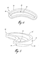
Fig. 3 is a side perspective view of a vane of the vane assembly ofFig. 2 ; -
Fig. 4 is a top perspective view of an outer grommet of the vane assembly ofFig. 2 ; -
Fig. 5 is a front perspective view of the grommet ofFig. 4 ; -
Fig. 6 is a perspective view of an outer casing forming part of the vane assembly ofFig. 2 , with an inner shroud of the vane assembly being schematically shown in dotted lines; -
Fig. 7 is a side perspective view of an alternate vane that can be used in the vane assembly ofFig. 2 ; and -
Fig. 8 is a perspective view of the vane assembly ofFig. 2 . -
Fig.1 illustrates a gas turbine engine 10 of a type preferably provided for use in subsonic flight, generally comprising in serial flow communication afan 12 through which ambient air is propelled, a compressor section 14 for pressurizing the air, acombustor 16 in which the compressed air is mixed with fuel and ignited for generating an annular stream of hot combustion gases, and aturbine section 18 for extracting energy from the combustion gases. - Referring to
Fig. 2 , a rotor assembly, which can be for example thefan 12 or a low pressure compressor of the compressor section 14 (both shown inFig. 1 ), includes rotatingblades 22 which are surrounded by anengine casing 24. Thecasing 24 extends downstream of theblades 22 to form part of avane assembly 20. Thevane assembly 20 comprises aninner shroud 26 concentric with thecasing 24 and located downstream of therotating blades 22, theinner shroud 26 andcasing 24 defining an annulargas flow path 28 therebetween, and a plurality ofvanes 30 extending radially between theouter casing 24 and theinner shroud 26 downstream of therotor blades 22. Each of thevanes 30 has avane root 32 retained in thecasing 24, avane tip 34 retained in theinner shroud 26, and anairfoil portion 36 extending therebetween. Theairfoil portion 36 of eachvane 30 defines a relatively sharp leadingedge 38 and a relatively sharptrailing edge 40, such that an airflow coming from theblades 22 and passing through thevane assembly 20 will flow over thevane airfoil 36 from the leadingedge 38 to thetrailing edge 40. - Throughout this description, the axial, radial and circumferential directions are defined respectively with respect to the central axis, radius and circumference of the engine 10.
- Referring now to
Figs. 2-3 , thevane tip 34 may include a generallyrectangular slot 42 extending radially into the airfoil between the leading andtrailing edges corresponding web 44 of the inner shroud 26 (seeFig. 2 ) as disclosed in Applicant'sU.S. application No. 11/223,148 filed September 12, 2005 vane tip 34 can have any other configuration suitable for engagement with theinner shroud 26. - Referring particularly to
Fig. 2 , thevane root 32 comprises anend platform 46 defining aninner pressure surface 48 and an opposedouter surface 50. Theouter surface 50 includes astrap holder 52 which, when thevane 30 is part of thevane assembly 20, is circumferentially aligned with thestrap holders 52 of theremaining vanes 30. In the particular embodiment shown inFig. 3 , thestrap holder 52 is in the form of acircumferential groove 54 defined in theouter surface 50 for receiving acorresponding fastening strap 86 or other member used to fasten and retain in place thevanes 30 within theouter casing 24 of thevane assembly 20.Fig. 7 shows an alternate configuration for the strap holder 52', which includes two elongated and axially spaced apart fingers 56 extending radially outwardly from theouter surface 50. Alternate configurations for thestrap holder 52, 52' can also be used. - Referring back to
Fig. 3 , thevane root 32 further comprises an inner recessed orbutton portion 58 extending inwardly from theinner pressure surface 48 of theplatform 46, and connected to theairfoil portion 36. Theplatform 46 protrudes from thebutton portion 58 along at least one transverse direction of thevane 30, i.e. in a plane substantially perpendicular to thelongitudinal axis 60 of thevane 30 and in a direction substantially perpendicular to the fore-aft direction of the vane blade. In a particular embodiment, theplatform 46 protrudes outward from thebutton portion 58 around the entire perimeter thereof. Thebutton portion 58 in turn protrudes from theairfoil portion 36 along at least one transverse direction of thevane 30, and thebutton portion 58 protrudes from theairfoil portion 36 around the entire perimeter thereof. Therefore, therecessed portion 58, adjacent to theplatform 46 and interconnecting the airfoil portion and the platform, protrudes beyond a profile of the airfoil a distance less than the outer platform. In other words, both the inner recessedbutton portion 58 and theplatform 46 of theroot 32 protrude outwardly from the airfoil, however theplatform 46 protrudes further than the inner recessedportion 58. There accordingly defines a stepped root shape about the full perimeter thereof. In the embodiment shown, thebutton portion 58 has a shape (i.e. a transverse profile) generally corresponding to that of theairfoil portion 36. - The inner recessed
portion 58 will generally be referred to herein as the button portion. Thebutton portion 58 includes relatively blunt leading and trailing ends 62, 64, which respectively protrude from the leading and trailingedges airfoil portion 36. Thebutton portion 58 has a profile free of sharp edges. In use, thebutton portion 58 is received within an outer grommet 66 (seeFig. 7 ). As contact between thevane 30 andgrommet 66 occurs through thevane button 58 which is free of sharp edges, the risks of tearing thegrommet 66 during assembly and/or foreign object impact on the airfoils is reduced when compared, for example, to the risk of tearing a prior art grommet which usually surrounds relatively sharp leading and trailing edges of the airfoil itself. - Referring to
Fig. 6 , thecasing 24 has acircumferential wall 68 having aninner surface 70 delimiting theflow path 28 and anouter surface 72 opposite thereto. Vane-receivingopenings 74 are defined through thecasing wall 68 and are regularly distributed about the circumference of thecasing 24. Eachopening 74 has a shape generally corresponding to the shape of thebutton portion 58 of thevanes 30 but is enlarged relative thereto, while being configured such that theplatform 46 of the corresponding vane is prevented from passing therethrough. - Referring to
Figs. 4-5 , eachouter grommet 66 has acircumferential portion 76 defining anouter surface 78 adapted to sealingly engage theinner pressure surface 48 of theplatform 46 of the correspondingvane 30, and an inner surface 80 (seeFig. 5 ) adapted to sealingly engage theouter surface 72 of thecasing wall 68 around the correspondingopening 74. Thecircumferential portion 76 has aslot 82 defined therein, and alip 84 which extends radially inwardly around theslot 82. Theslot 82 andlip 84 are configured to respectively sealingly receive and sealingly surround thebutton portion 58 of the correspondingvane 30. Thelip 84 is also configured to sealingly engage the perimeter of thecorresponding opening 74 in thecasing wall 68 around thebutton portion 58. Thecircumferential portion 76 andlip 84 of thegrommet 66 have a shape following a profile of thebutton portion 58, and as such of theairfoil portion 36 of thevane 30, thus minimizing the volume and weight of thegrommet 66. Thegrommet 66 is made of a flexible, stretchable material, for example a silicon rubber, such as to be readily installed around thecorresponding button portion 58. In a particular embodiment, thegrommet 66 is made through an injection molding process. - In use, each
grommet 66 is thus stretched and installed around thebutton portion 58 of the correspondingvane 30, with thecircumferential portion 76 resting against theinner pressure surface 48 of theplatform 46, as shown inFig. 7 . In a particular embodiment, thegrommet 66 is stretched so that theplatform 46 is passed through thegrommet slot 82, and thegrommet 66 is released when in place, thelip 84 surrounding thebutton portion 58 in a slightly stretched state to ensure a sealed engagement therewith. Thevane 30 is then inserted into thecasing 24 through thecorresponding opening 74 in thecasing wall 68, and moved radially inwardly until thevane tip 34 is engaged with theinner shroud 26 and thegrommet lip 84 is engaged with the perimeter of theopening 74. As can be seen inFig. 8 , astrap 86 is then placed around thecasing 24 in the alignedstrap holders 52, 52' of thevane platforms 46, and thestrap 86 is tightened until thecircumferential portion 76 of eachgrommet 66 is sufficiently compressed between theinner pressure surface 48 of the correspondingplatform 46 and theouter surface 72 of thecasing wall 68 to seal the connection between thevanes 30 and thecasing 24. Alternately, vane retaining mechanisms other than the strap can be used in order to maintain thevanes 30 in sealed engagement with theouter casing 24. - The
vanes 30 of thevane assembly 20 are thus attached directly to thecasing 24 without the need of an additional outer shroud. As such, damaged vanes can be replaced without the need to disassemble the entire engine 10, by simply removing thestrap 86, sliding the damaged vane out of thecorresponding opening 74 in thecasing wall 68, sliding a new vane in place through theopening 74, and replacing thestrap 86. In prior art configurations in which an additional outer shroud is used, this is not easily possible. - The
blunt button portion 58 minimizes the risks of damage to thegrommet 66 by thevane 30 through elimination of sharp edges in contact with thegrommet 66. Theenlarged button portion 58 also provides for thecorresponding opening 74 in thecasing wall 68 to be substantially larger than theairfoil portion 36 andtip 34 of thevane 30, facilitating the installation of thevane 30 which is done radially through theopening 74. - The
vane assembly 20 eliminates the need for adhesives or potting components to retain thevane roots 32, which reduces costs and simplifies production and maintenance operations. - The absence of an outer shroud also lowers the overall weight of the engine 10. In addition, the
larger openings 74 defined in thecasing wall 68 lower the weight of thecasing 24. The weight of thecasing 24 is additionally lowered since the thickness of thecasing wall 68 can be reduced with respect to a casing of the prior art used in conjunction with an outer shroud, as any loads transferred between a containment zone of the engine 10 and engine mounts in the event of foreign object damage or a fan blade failure are attenuated. Having alighter casing 24 reduces the overall weight of the engine 10, thus improving engine performances. - The above description is meant to be exemplary only, and one skilled in the art will recognize that changes may be made to the embodiments described without department from the scope of the invention disclosed. For example, the invention can be applied to vane assemblies contained in the casing of rotor assemblies other than fans and low pressure compressors. Other modifications which fall within the scope of the present invention will be apparent to those skilled in the art, in light of a review of this disclosure, and such modifications are intended to fall within the appended claims.
Claims (9)
- A vane assembly for a gas turbine engine having an outer casing surrounding rotating blades of a rotor, the assembly comprising:a tubular wall portion of the outer casing located downstream of the blades, the wall portion having a series of circumferentially and regularly spaced apart openings defined therethrough;an inner shroud located inwardly of and concentric with the wall portion, the inner shroud and wall portion defining a flow path therebetween;a grommet sealingly engaged in each one of the openings, the grommet having a slot defined therethrough; anda vane for each grommet and extending radially between the wall portion and the inner shroud, each said vane having an airfoil portion extending between a tip and a vane root, the tip being engaged to the inner shroud, the vane root including an outer platform and an inner button portion interconnecting the platform and the airfoil portion, the platform being located outside of the outer casing and having a configuration preventing the platform from passing through the corresponding opening, the airfoil portion having a configuration allowing the airfoil to pass through the slot of the grommet, and the button portion being sealingly received in the slot of the grommet.
- The vane assembly as defined in claim 1, wherein the at least part of the vane root is free of sharp edges.
- The vane assembly as defined in claim 1 or 2, wherein a portion of the vane root is located outside of the casing and defines a strap holder therein, the vane assembly further comprising a fastening strap received in the strap holder of each said vane and tightly surrounding the outer casing, the strap producing an inwardly directed force on the portion of the vane root located outside of the outer casing.
- The vane assembly as defined in claim 1 or 2, wherein the platform has a strap holder defined therein opposite of the button portion, and the vane assembly further comprises a fastening strap received in the strap holder of the platform of each said vane and surrounding the outer casing, the strap producing an inwardly directed force on the vane platform.
- The vane assembly as defined in claim 4, wherein the grommet includes a portion extending around the opening and being compressed between the outer casing and the platform.
- The vane assembly as defined in any preceding claim, wherein the button portion has a profile corresponding to that of the airfoil portion.
- The vane assembly as defined in any preceding claim, wherein the button portion protrudes from the airfoil portion around an entire perimeter thereof.
- The vane assembly as defined in claim 7, wherein the outer platform protrudes from the button portion around an entire perimeter thereof.
- A rotor assembly for a gas turbine engine, the rotor assembly comprising:rotating blades; anda vane assembly as defined in any preceding claim.
Applications Claiming Priority (3)
| Application Number | Priority Date | Filing Date | Title |
|---|---|---|---|
| US11/223,129 US7530782B2 (en) | 2005-09-12 | 2005-09-12 | Foreign object damage resistant vane assembly |
| US11/467,413 US7628578B2 (en) | 2005-09-12 | 2006-08-25 | Vane assembly with improved vane roots |
| EP06790673.5A EP1926887B1 (en) | 2005-09-12 | 2006-09-12 | Vane assembly with improved vane roots |
Related Parent Applications (1)
| Application Number | Title | Priority Date | Filing Date |
|---|---|---|---|
| EP06790673.5 Division | 2006-09-12 |
Publications (2)
| Publication Number | Publication Date |
|---|---|
| EP2535521A2 true EP2535521A2 (en) | 2012-12-19 |
| EP2535521A3 EP2535521A3 (en) | 2013-01-02 |
Family
ID=37864591
Family Applications (2)
| Application Number | Title | Priority Date | Filing Date |
|---|---|---|---|
| EP12183342A Withdrawn EP2535521A3 (en) | 2005-09-12 | 2006-09-12 | Vane assembly with improved vane roots |
| EP06790673.5A Active EP1926887B1 (en) | 2005-09-12 | 2006-09-12 | Vane assembly with improved vane roots |
Family Applications After (1)
| Application Number | Title | Priority Date | Filing Date |
|---|---|---|---|
| EP06790673.5A Active EP1926887B1 (en) | 2005-09-12 | 2006-09-12 | Vane assembly with improved vane roots |
Country Status (5)
| Country | Link |
|---|---|
| US (1) | US7628578B2 (en) |
| EP (2) | EP2535521A3 (en) |
| JP (1) | JP2009508032A (en) |
| CA (1) | CA2622017C (en) |
| WO (1) | WO2007030925A1 (en) |
Families Citing this family (19)
| Publication number | Priority date | Publication date | Assignee | Title |
|---|---|---|---|---|
| US7614848B2 (en) * | 2006-10-10 | 2009-11-10 | United Technologies Corporation | Fan exit guide vane repair method and apparatus |
| US20110268575A1 (en) * | 2008-12-19 | 2011-11-03 | Volvo Aero Corporation | Spoke for a stator component, stator component and method for manufacturing a stator component |
| US8206100B2 (en) * | 2008-12-31 | 2012-06-26 | General Electric Company | Stator assembly for a gas turbine engine |
| GB0905729D0 (en) | 2009-04-03 | 2009-05-20 | Rolls Royce Plc | Stator vane assembly |
| US8356975B2 (en) * | 2010-03-23 | 2013-01-22 | United Technologies Corporation | Gas turbine engine with non-axisymmetric surface contoured vane platform |
| US9976433B2 (en) | 2010-04-02 | 2018-05-22 | United Technologies Corporation | Gas turbine engine with non-axisymmetric surface contoured rotor blade platform |
| US8696311B2 (en) | 2011-03-29 | 2014-04-15 | Pratt & Whitney Canada Corp. | Apparatus and method for gas turbine engine vane retention |
| US8998574B2 (en) | 2011-09-01 | 2015-04-07 | Pratt & Whitney Canada Corp. | Spring-tensioned stator restraining strap |
| US9951639B2 (en) | 2012-02-10 | 2018-04-24 | Pratt & Whitney Canada Corp. | Vane assemblies for gas turbine engines |
| US9062560B2 (en) * | 2012-03-13 | 2015-06-23 | United Technologies Corporation | Gas turbine engine variable stator vane assembly |
| FR2989130B1 (en) * | 2012-04-05 | 2014-03-28 | Snecma | COMPRESSOR RECTIFIER STAGE FOR A TURBOMACHINE |
| US9045984B2 (en) | 2012-05-31 | 2015-06-02 | United Technologies Corporation | Stator vane mistake proofing |
| US9506361B2 (en) * | 2013-03-08 | 2016-11-29 | Pratt & Whitney Canada Corp. | Low profile vane retention |
| US9840929B2 (en) * | 2013-05-28 | 2017-12-12 | Pratt & Whitney Canada Corp. | Gas turbine engine vane assembly and method of mounting same |
| JP6221544B2 (en) | 2013-09-18 | 2017-11-01 | 株式会社Ihi | Seal for turbofan engine |
| US10801343B2 (en) * | 2016-12-16 | 2020-10-13 | Pratt & Whitney Canada Corp. | Self retaining face seal design for by-pass stator vanes |
| CN108931349B (en) * | 2018-04-09 | 2020-08-18 | 南京航空航天大学 | Centrifugal force simulation test device used in high-speed hard object impact test |
| US11060411B2 (en) * | 2019-03-22 | 2021-07-13 | Pratt & Whitney Canada Corp. | Inner shroud assembly for stator vanes |
| US11454127B2 (en) * | 2019-11-22 | 2022-09-27 | Pratt & Whitney Canada Corp. | Vane for gas turbine engine |
Family Cites Families (29)
| Publication number | Priority date | Publication date | Assignee | Title |
|---|---|---|---|---|
| CA840224A (en) | 1970-04-28 | L. Seiwert David | Mounting of blades in an axial flow compressor | |
| GB599391A (en) * | 1945-05-25 | 1948-03-11 | Power Jets Res & Dev Ltd | Improvements in and relating to axial flow compressors, turbines and the like machines |
| GB572859A (en) * | 1942-04-03 | 1945-10-26 | Armstrong Siddeley Motors Ltd | Mounting the blades of axial-flow, rotary compressors or turbines |
| US2914300A (en) * | 1955-12-22 | 1959-11-24 | Gen Electric | Nozzle vane support for turbines |
| DE1503628B2 (en) * | 1965-10-22 | 1974-06-27 | Turbon Ventilatoren- Und Apparatebau Gmbh, 1000 Berlin | Impeller |
| FR1542561A (en) | 1967-07-07 | Snecma | Turbomachinery blade attachment device | |
| FR1583838A (en) | 1968-04-30 | 1969-12-05 | ||
| US3849023A (en) | 1973-06-28 | 1974-11-19 | Gen Electric | Stator assembly |
| US3985465A (en) | 1975-06-25 | 1976-10-12 | United Technologies Corporation | Turbomachine with removable stator vane |
| US4180371A (en) | 1978-03-22 | 1979-12-25 | Avco Corporation | Composite metal-ceramic turbine nozzle |
| US4378961A (en) * | 1979-01-10 | 1983-04-05 | United Technologies Corporation | Case assembly for supporting stator vanes |
| GB2043798B (en) | 1979-03-14 | 1983-01-12 | Rolls Royce | Gas turbine stator vane assembly |
| JPS59180006A (en) | 1983-03-30 | 1984-10-12 | Hitachi Ltd | Gas turbine stator blade segment |
| US4907944A (en) | 1984-10-01 | 1990-03-13 | General Electric Company | Turbomachinery blade mounting arrangement |
| US4728258A (en) * | 1985-04-25 | 1988-03-01 | Trw Inc. | Turbine engine component and method of making the same |
| FR2600379B1 (en) * | 1986-06-18 | 1988-09-02 | Snecma | MULTIFLUX TURBOJET BLOWER RECTIFIER |
| FR2610673B1 (en) * | 1987-02-05 | 1991-03-15 | Snecma | MULTIFLUX TURBOREACTOR WITH EXTERNAL CROWN OF FREQUENCY BLOWER RECTIFIER ON THE CRANKCASE |
| DE3863683D1 (en) | 1987-04-13 | 1991-08-22 | Bbc Brown Boveri & Cie | FASTENING A COVER PLATE ON THE BLADE OF A TURBO MACHINE BLADE. |
| US5074752A (en) | 1990-08-06 | 1991-12-24 | General Electric Company | Gas turbine outlet guide vane mounting assembly |
| DE4117025A1 (en) | 1991-05-24 | 1992-11-26 | Halberg Maschbau Gmbh & Co | SWIRL REGULATOR FOR CENTRIFUGAL PUMPS |
| US5494404A (en) | 1993-12-22 | 1996-02-27 | Alliedsignal Inc. | Insertable stator vane assembly |
| US6450766B1 (en) * | 1999-08-09 | 2002-09-17 | United Technologies Corporation | Stator vane blank and method of forming the vane blank |
| US6409472B1 (en) * | 1999-08-09 | 2002-06-25 | United Technologies Corporation | Stator assembly for a rotary machine and clip member for a stator assembly |
| US6543995B1 (en) | 1999-08-09 | 2003-04-08 | United Technologies Corporation | Stator vane and stator assembly for a rotary machine |
| US6494677B1 (en) * | 2001-01-29 | 2002-12-17 | General Electric Company | Turbine nozzle segment and method of repairing same |
| US6854960B2 (en) | 2002-06-24 | 2005-02-15 | Electric Boat Corporation | Segmented composite impeller/propeller arrangement and manufacturing method |
| JP2004197622A (en) * | 2002-12-17 | 2004-07-15 | Ishikawajima Harima Heavy Ind Co Ltd | Turbine compressor vane |
| US7370467B2 (en) * | 2003-07-29 | 2008-05-13 | Pratt & Whitney Canada Corp. | Turbofan case and method of making |
| JP2007500298A (en) * | 2003-07-29 | 2007-01-11 | プラット アンド ホイットニー カナダ コーポレイション | Turbofan case and manufacturing method |
-
2006
- 2006-08-25 US US11/467,413 patent/US7628578B2/en active Active
- 2006-09-12 WO PCT/CA2006/001499 patent/WO2007030925A1/en not_active Ceased
- 2006-09-12 EP EP12183342A patent/EP2535521A3/en not_active Withdrawn
- 2006-09-12 EP EP06790673.5A patent/EP1926887B1/en active Active
- 2006-09-12 JP JP2008529435A patent/JP2009508032A/en active Pending
- 2006-09-12 CA CA2622017A patent/CA2622017C/en active Active
Also Published As
| Publication number | Publication date |
|---|---|
| EP1926887A4 (en) | 2010-04-07 |
| WO2007030925A1 (en) | 2007-03-22 |
| CA2622017C (en) | 2013-04-23 |
| US20070098548A1 (en) | 2007-05-03 |
| EP2535521A3 (en) | 2013-01-02 |
| CA2622017A1 (en) | 2007-03-22 |
| EP1926887A1 (en) | 2008-06-04 |
| JP2009508032A (en) | 2009-02-26 |
| EP1926887B1 (en) | 2013-09-11 |
| US7628578B2 (en) | 2009-12-08 |
Similar Documents
| Publication | Publication Date | Title |
|---|---|---|
| EP1924758B1 (en) | Vane assembly with outer grommets | |
| US7628578B2 (en) | Vane assembly with improved vane roots | |
| EP1762703B1 (en) | Foreign object damage resistant vane assembly | |
| US5569019A (en) | Tear-away composite fan stator vane | |
| CA2622013C (en) | Vane assembly with grommet | |
| EP2725233A1 (en) | Rotor blade for a compressor | |
| EP2971568B1 (en) | Flap seal for a fan of a gas turbine engine | |
| EP3266986B1 (en) | Segmented stator assembly with potting for vane retainment | |
| EP1605134B1 (en) | Device for balancing a gas turbine rotor and gas turbine engine comprising such a device | |
| US12221894B2 (en) | Compressor with anti-ice inlet | |
| CA2597443A1 (en) | Vane assembly with improved vane roots | |
| CA2597268A1 (en) | Vane assembly with outer grommets | |
| US20200063590A1 (en) | Sealing member for gas turbine engine |
Legal Events
| Date | Code | Title | Description |
|---|---|---|---|
| PUAL | Search report despatched |
Free format text: ORIGINAL CODE: 0009013 |
|
| PUAI | Public reference made under article 153(3) epc to a published international application that has entered the european phase |
Free format text: ORIGINAL CODE: 0009012 |
|
| AC | Divisional application: reference to earlier application |
Ref document number: 1926887 Country of ref document: EP Kind code of ref document: P |
|
| AK | Designated contracting states |
Kind code of ref document: A2 Designated state(s): DE FR GB |
|
| AK | Designated contracting states |
Kind code of ref document: A3 Designated state(s): DE FR GB |
|
| RIC1 | Information provided on ipc code assigned before grant |
Ipc: F01D 9/04 20060101AFI20121126BHEP |
|
| STAA | Information on the status of an ep patent application or granted ep patent |
Free format text: STATUS: THE APPLICATION IS DEEMED TO BE WITHDRAWN |
|
| 18D | Application deemed to be withdrawn |
Effective date: 20130703 |