EP2535244A1 - Vehicle collision load transmission structure - Google Patents
Vehicle collision load transmission structure Download PDFInfo
- Publication number
- EP2535244A1 EP2535244A1 EP11739602A EP11739602A EP2535244A1 EP 2535244 A1 EP2535244 A1 EP 2535244A1 EP 11739602 A EP11739602 A EP 11739602A EP 11739602 A EP11739602 A EP 11739602A EP 2535244 A1 EP2535244 A1 EP 2535244A1
- Authority
- EP
- European Patent Office
- Prior art keywords
- vehicle
- seat
- load transmission
- load
- base portion
- Prior art date
- Legal status (The legal status is an assumption and is not a legal conclusion. Google has not performed a legal analysis and makes no representation as to the accuracy of the status listed.)
- Withdrawn
Links
- 230000005540 biological transmission Effects 0.000 title claims abstract description 81
- 238000003780 insertion Methods 0.000 description 14
- 230000037431 insertion Effects 0.000 description 14
- 238000005192 partition Methods 0.000 description 7
- 229910000831 Steel Inorganic materials 0.000 description 5
- 239000010959 steel Substances 0.000 description 5
- XAGFODPZIPBFFR-UHFFFAOYSA-N aluminium Chemical compound [Al] XAGFODPZIPBFFR-UHFFFAOYSA-N 0.000 description 3
- 229910052782 aluminium Inorganic materials 0.000 description 3
- 238000004519 manufacturing process Methods 0.000 description 2
- 239000000463 material Substances 0.000 description 2
- 229920005989 resin Polymers 0.000 description 2
- 239000011347 resin Substances 0.000 description 2
- 230000000694 effects Effects 0.000 description 1
- 238000000034 method Methods 0.000 description 1
Images


Classifications
-
- B—PERFORMING OPERATIONS; TRANSPORTING
- B62—LAND VEHICLES FOR TRAVELLING OTHERWISE THAN ON RAILS
- B62D—MOTOR VEHICLES; TRAILERS
- B62D21/00—Understructures, i.e. chassis frame on which a vehicle body may be mounted
- B62D21/15—Understructures, i.e. chassis frame on which a vehicle body may be mounted having impact absorbing means, e.g. a frame designed to permanently or temporarily change shape or dimension upon impact with another body
- B62D21/157—Understructures, i.e. chassis frame on which a vehicle body may be mounted having impact absorbing means, e.g. a frame designed to permanently or temporarily change shape or dimension upon impact with another body for side impacts
-
- B—PERFORMING OPERATIONS; TRANSPORTING
- B60—VEHICLES IN GENERAL
- B60N—SEATS SPECIALLY ADAPTED FOR VEHICLES; VEHICLE PASSENGER ACCOMMODATION NOT OTHERWISE PROVIDED FOR
- B60N2/00—Seats specially adapted for vehicles; Arrangement or mounting of seats in vehicles
- B60N2/24—Seats specially adapted for vehicles; Arrangement or mounting of seats in vehicles for particular purposes or particular vehicles
- B60N2/42—Seats specially adapted for vehicles; Arrangement or mounting of seats in vehicles for particular purposes or particular vehicles the seat constructed to protect the occupant from the effect of abnormal g-forces, e.g. crash or safety seats
- B60N2/4207—Seats specially adapted for vehicles; Arrangement or mounting of seats in vehicles for particular purposes or particular vehicles the seat constructed to protect the occupant from the effect of abnormal g-forces, e.g. crash or safety seats characterised by the direction of the g-forces
- B60N2/4235—Seats specially adapted for vehicles; Arrangement or mounting of seats in vehicles for particular purposes or particular vehicles the seat constructed to protect the occupant from the effect of abnormal g-forces, e.g. crash or safety seats characterised by the direction of the g-forces transversal
-
- B—PERFORMING OPERATIONS; TRANSPORTING
- B60—VEHICLES IN GENERAL
- B60N—SEATS SPECIALLY ADAPTED FOR VEHICLES; VEHICLE PASSENGER ACCOMMODATION NOT OTHERWISE PROVIDED FOR
- B60N2/00—Seats specially adapted for vehicles; Arrangement or mounting of seats in vehicles
- B60N2/24—Seats specially adapted for vehicles; Arrangement or mounting of seats in vehicles for particular purposes or particular vehicles
- B60N2/42—Seats specially adapted for vehicles; Arrangement or mounting of seats in vehicles for particular purposes or particular vehicles the seat constructed to protect the occupant from the effect of abnormal g-forces, e.g. crash or safety seats
- B60N2/427—Seats or parts thereof displaced during a crash
Definitions
- the present invention relates to a vehicle collision load transmission structure in which a collision load applied from a vehicle lateral side can be received by a load transmission body via a seat rod of one seat and can be transmitted from the load transmission body to a vehicle side wall positioned opposite to an impact area via a seat rod of the other seat.
- a load transmission body 110 is disposed in a position corresponding to a console box (not shown) between a driver seat 101 and a passenger seat 102.
- the load transmission body 110 is composed of a base portion 114 secured to a vehicle floor F, and a load receiving portion 115 disposed on the base portion 114.
- the load receiving portion 115 is a portion to which seat rods 101r and 102r of the driver seat 101 and the passenger seat 102 can contact when a vehicle is hit from a lateral side thereof.
- the load receiving portion 115 has a box-shaped member of which the interior portion is segmented and reinforced by a plurality of vertical walls 115w extending in a vehicle width direction.
- the base portion 114 is a rigid box-shaped member that is capable of supporting the load receiving portion 115 in the same height as the seat rods 101r and 102r of the driver seat 101 and the passenger seat 102. Further, the base portion 114 has leg portions that are formed in four corners thereof and are bolted on an elongated central raised portion Fa of the floor F.
- the load receiving portion 115 is formed as the box-shaped member, and the interior portion thereof is segmented by a plurality of vertical walls 115w. Further, the base portion 114 is also formed as the rigid box-shaped member. That is, both of the load receiving portion 115 and the base portion 114 of the load transmission body 110 are respectively formed so as to have a high strength. Therefore, as shown in FIG. 7(C) , for example, when a collision load S is applied to the load receiving portion 115 of the load transmission body 110 via the seat rod 102r of the passenger seat 102, the floor F can be deformed instead of deforming of the load transmission body 110, so that the load transmission body 110 can be tilted toward the driver seat 101. As a result, the load receiving portion 115 of the load transmission body 110 can be inclined downwardly from a horizontal posture. This may reduce a collision load transmission efficiency between the load transmission body 110 and the seat rods 101r of the driver seat 101.
- the present invention has been made in order to solve problems described above. Accordingly, it is an object of the present invention to prevent a load transmission efficiency from a seat rod of one seat to a seat rod of the other seat from being reduced when a vehicle is hit from a lateral side thereof.
- An invention defined in claim 1 provides a vehicle collision load transmission structure which may include seat rods that are respectively disposed in right and left seats so as to extend in a vehicle width direction, and a load transmission body that is disposed on a vehicle floor so as to be positioned between the seat rods of the right and left seats, in which a collision load applied from a vehicle lateral side can be received by the load transmission body via the seat rod of one of the seats and can be transmitted from the load transmission body to a vehicle side wall positioned opposite to an impact area via the seat rod of the other of the seats, wherein the load transmission body is composed of a base portion that is secured to the vehicle floor, and a load receiving portion that is disposed on the base portion and is constructed such that the seat rods can contact the same, and wherein the base portion is constructed so as to be deformed more easily than the vehicle floor due to application of the collision load in the vehicle width direction.
- the base portion of the load transmission body is constructed so as to be deformed more easily than the vehicle floor due to application of the collision load in the vehicle width direction. Therefore, when the collision load in the vehicle width direction is applied to the load receiving portion of the load transmission body via the seat rod of one of the seats, the base portion of the load transmission body can be deformed in a direction of the collision load while the vehicle floor is not substantially deformed. Thus, because the vehicle floor is not substantially deformed, the load transmission body can be prevented from being tilted. As a result, the load receiving portion disposed on the base portion can be displaced in the direction of the collision load, so as to contact the seat rod of the other of the seats. That is, unlike the conventional structure, the load receiving portion can be prevented from contacting the seat rod of the other of the seats while it is inclined downwardly. Thus, the collision load can be effectively transmitted from the seat rod of one of the seats to the seat rod of the other of the seats.
- the base portion is formed as a tunnel-shaped member of which the front and rear sides in a vehicle longitudinal direction are opened. Therefore, when the collision load in the vehicle width direction is applied to the base portion, the base portion can be easily deformed in the direction of the collision load.
- the base portion is formed as a press formed article. Therefore, manufacturing costs of the base portion can be reduced.
- a load transmission efficiency from a seat rod of one seat to a seat rod of the other seat can be increased.
- a vehicle collision load transmission structure according to Embodiment 1 of the present invention will be hereinafter described with reference to FIGS. 1 to 6 . Further, forward and backward, rightward and leftward, and upward and downward in the drawings respectively correspond to forward and backward, rightward and leftward, and upward and downward of a vehicle.
- the vehicle collision load transmission structure is a structure in which a collision load applied from a vehicle lateral side can be received by a load transmission body 10 via a seat rod 2r of one seat (e.g., a passenger seat 2 shown in FIG. 2 (a chain double-dashed line)) and can be transmitted from the load transmission body 10 to a vehicle side wall positioned opposite to an impact area via a seat rod 3r of the other seat (a driver seat 3).
- a seat rod 2r of one seat e.g., a passenger seat 2 shown in FIG. 2 (a chain double-dashed line)
- the seat rod 3r of the driver seat 3 is disposed in an interior portion of a seat cushion (not shown) of the driver seat 3 and is positioned so as to extend in a vehicle width direction.
- the seat rod 2r of the passenger seat 2 is disposed in an interior portion of a seat cushion (not shown) of the passenger seat 2 and is positioned so as to extend in the vehicle width direction in the same height as the seat rod 3r of the driver seat 3 ( FIGS. 2 and 3 ).
- the load transmission body 10 is positioned under an article storing portion 5s of a consol box 5. Further, as shown in FIG. 3 , the load transmission body 10 is disposed within an ornamental outer shell 5k of the consol box 5.
- the load transmission body 10 is interposed between the seat rod 3r of the driver seat 3 and the seat rod 2r of the passenger seat 2 positioned on both sides thereof in the vehicle width direction without contacting the same. Further, in FIGS. 2 and 3 , in order to clarify a relation among the seat rods 2r and 3r and the load transmission body 10, a distance between the members 2r and 10 and a distance between the members 3r and 10 are exaggerated.
- the load transmission body 10 is a member that is capable of transmitting the collision load applied from the seat rod 2r of one seat (e.g., the passenger seat 2) to the seat rod 3r of the other seat (e.g., the driver seat 3).
- the load transmission body 10 is composed of a base portion 20 that is secured to an elongated central raised portion Fa of a vehicle floor F, and a load receiving portion 30 that is disposed on the base portion 20 and is capable of receiving the collision load.
- the vehicle floor F is formed of, for example, a steel plate having a thickness of 1.2 mm.
- the base portion 20 of the load transmission body 10 is a base member that is capable of horizontally supporting the load receiving portion 30 (which will be hereinafter described) in the same height as the seat rod 3r of the driver seat 3 and the seat rod 2r of the passenger seat 2.
- the base portion 20 is composed of right and left vertical wall portions 22, and a ceiling plate portion 25 that is horizontally bridged between upper end portions of the vertical wall portions 22. That is, the base portion 20 is formed as a tunnel-shaped member of which the front and rear sides in a vehicle longitudinal direction are opened. Further, the right and left vertical wall portions 22 respectively have flanged portions 22f that are formed in lower end portions thereof.
- Each of the flanged portions 22f is formed by folding the lower end portions of the vertical wall portions 22 outwardly over a desired width in the vehicle width direction.
- the right and left flanged portions 22f are portions that are connected to the elongated central raised portion Fa of the vehicle floor F.
- the right and left flanged portions 22f have bolt insertion holes 22h into which connecting bolts B1 are inserted.
- the bolt insertion holes 22h are positioned to be aligned with bolt insertion holes (not shown) that are formed in the elongated central raised portion Fa.
- the right and left vertical wall portions 22 of the base portion 20 respectively have vertically elongated openings 22w for strength controlling purposes.
- Each of the openings 22w is formed in a central portion of each of the vertical wall portions 22.
- the ceiling plate portion 25 of the base portion 20 has a rectangular table shape. Further, the ceiling plate portion 25 has bolt insertion holes 25h that are formed in four corner portions thereof, i.e., front and rear and right and left corner portions thereof, so that the load receiving portion 30 (which will be hereinafter described) can be bolted on the ceiling plate portion 25.
- the base portion 20 is formed by, for example, press forming a steel plate (2.0 mm). Further, as previously described, the base portion 20 is formed as the tunnel-shaped member of which the front and rear sides are opened. Therefore, the base portion 20 can be deformed in a direction of the collision load more easily than the vehicle floor F (the steel plate having the 1.2 mm thickness) due to application of the collision load in the vehicle width direction. In addition, the base portion 20 can be reduced in weight because the front and rear sides thereof are opened, i.e., because no wall portions are present in the front and rear sides thereof.
- the load receiving portion 30 of the load transmission body 10 is a portion to which end portions of the seat rods 3r and 2r of the driver seat 3 and the passenger seat 2 can contact with interleaving the ornamental outer shell 5k of the consol box 5 when the vehicle is hit from a lateral side thereof.
- the load receiving portion 30 has a width greater than the base portion 20, so that right and left end portions thereof can be projected in the vehicle width direction beyond right and left end portions of the base portion.
- a distance between the seat rod 3r of the driver seat 3 and the load receiving portion 30 and a distance between the seat rod 2r of the passenger seat 2 and the load receiving portion 30 can be reduced as much as possible.
- the load receiving portion 30 is composed of a receiving portion main body 32 having a rectangular cylindrical shape, a flange portion 34 projected rearwardly from a rear end periphery of a lower end portion of the receiving portion main body 32 and having a constant width, and a pair of side plate portions 36 ( FIG. 2 and other figures) covering a right end face and a left end face of the receiving portion main body 32.
- the receiving portion main body 32 of the load receiving portion 30 is constructed of a front plate portion 33f, an upper plate portion 33u, a lower plate portion 33d and a rear plate portion 33b, so as to have the rectangular cylindrical shape that extends in the vehicle width direction.
- An interior portion of the receiving portion main body 32 is vertically separated by a transverse partition plate portion 32m, so as to have upper and lower cavities.
- the upper cavity formed in the receiving portion main body 32 by the transverse partition plate portion 32m is segmented at regular intervals by two vertical partition plate portions 32w that extend in the vehicle width direction. Further, as shown in FIG.
- the seat rod 3r and the seat rod 2r are positioned such that the load applied therefrom can be received in an intersection portion of the transverse partition plate portion 32m and a front side one of the vertical partition plate portions 32w of the receiving portion main body 32.
- the load receiving portion 30 may have a desired strength that is required to bear the collision load S in the vehicle width direction.
- a substantially rear half portion of the lower plate portion 33d of the receiving portion main body 32 is formed as a flattened portion, so as to be seated on the ceiling plate portion 25 of the base portion 20.
- the flange portion 34 of the load receiving portion 30 is formed as an extension of the flattened portion of the lower plate portion 33d.
- a substantially front half portion of the lower plate portion 33d is inclined upwardly and forwardly
- the lower plate portion 33d of the receiving portion main body 32 and the flange portion 34 respectively have bolt insertion holes 32h and 34h ( FIGS. 2 and 4 ) into which connecting bolts B3 ( FIG. 1 ) are inserted.
- the bolt insertion holes 32h and 34h are positioned to be aligned with the bolt insertion holes 25h formed in the ceiling plate portion 25 of the base portion 20.
- the upper plate portion 33u of the receiving portion main body 32 has bolt insertion holes 32x that are formed in right and left portions of a rear portion thereof, so that the receiving portion main body 32 can be bolted on the article storing portion 5s of the consol box 5.
- the receiving portion main body 32 and the flange portion 34 of the load receiving portion 30 are constructed of an aluminum plate having a thickness of 2 mm. Further, as shown in FIG. 2 and other figures, each of the pair of side plate portions 36 covering the right end face and the left end face of the receiving portion main body 32 has a rectangular shape that extends in the vehicle longitudinal direction and has a size that is capable of covering an area in which the seat rod 3r or 2r contacts.
- the bolt insertion holes 22h of the flanged portions 22f of the base portion 20 are aligned with the bolt insertion holes (not shown) of the elongated central raised portion Fa of the vehicle floor F, so that the base portion 20 can be secured to the vehicle floor using the connecting bolts B1 ( FIG. 1 ).
- the ceiling plate portion 25 of the base portion 20 can be held horizontally.
- the bolt insertion holes 32h and 34h of the receiving portion main body 32 and the flange portion 34 of the load receiving portion 30 are aligned with the bolt insertion holes 25h formed in the ceiling plate portion 25 of the base portion 20, so that the load receiving portion 30 can be secured to the ceiling plate portion 25 of the base portion 20 using the connecting bolts B3 ( FIGS. 1 and 2 and other figures).
- bolt insertion holes (not shown) of the article storing portion 5s of the consol box 5 are aligned with the bolt insertion holes 32x of the upper plate portion 33u of the load receiving portion 30, so that the article storing portion 5s can be secured to the upper plate portion 33u of the load receiving portion 30 using connecting bolts B4.
- the load transmission body 10 and the article storing portion 5s can be covered by the ornamental outer shell 5k of the consol box 5.
- the collision load S when the collision load S is applied from left of the vehicle, a left center pillar (not shown) is pressed into a vehicle cabin due to the collision load S, so that the passenger seat 2 is pressed toward the driver seat 3. As a result, the collision load S can be transmitted to the load receiving portion 30 of the load transmission body 10 via the seat rod 2r of the passenger seat 2.
- the collision load S When the collision load S is applied to the load receiving portion 30 from the seat rod 2r of the passenger seat 2, the collision load S can be applied to the base portion 20 supporting the load receiving portion 30 via the load receiving portion 30.
- the base portion 20 is formed as the tunnel-shaped member of which the front and rear sides are opened, so as to be easily deformed compared with the vehicle floor F due to application of the collision load S. Therefore, as shown in FIG. 6 , when the collision load S is applied to the base portion 20, only the base portion 20 can be deformed in the direction of the collision load S while the vehicle floor F is not substantially deformed, so that the load receiving portion 30 supported by the base portion 20 moves in the direction of the collision load S. That is, the load transmission body 10 can be prevented from being tilted, so that the load receiving portion 30 can contact the seat rod 3r of the drive seat 3 while moving in the direction of the collision load S. As a result, the collision load S can effectively be transmitted from the seat rod 2r of the passenger seat 2 to the seat rod 3r of the drive seat 3 via the load transmission body 10, and then be transmitted to a right center pillar (not shown).
- the base portion 20 of the load transmission body 10 is constructed so as to be deformed in the direction of the collision load S more easily than the vehicle floor F due to application of the collision load S in the vehicle width direction. Therefore, when the collision load S in the vehicle width direction is applied to the load receiving portion 30 of the load transmission body 10 via the seat rod 2r of the passenger seat 2, the base portion 20 of the load transmission body 10 can be deformed in the direction of the collision load S while the vehicle floor F is not substantially deformed. Thus, because the vehicle floor F is not substantially deformed, the load transmission body 10 can be prevented from being tilted.
- the load receiving portion 30 disposed on the base portion 20 can be displaced in the direction of the collision load S, so as to contact the seat rod 3r of the drive seat 3. That is, unlike the conventional structure, the load receiving portion 30 can be prevented from contacting the seat rod 3r of the drive seat 3 while it is inclined downwardly.
- the collision load S can be effectively transmitted from the seat rod 2r of the passenger seat 2 to the seat rod 3r of the drive seat 3.
- the base portion 20 is formed as the tunnel-shaped member of which the front and rear sides in the vehicle longitudinal direction are opened. Therefore, when the collision load S in the vehicle width direction is applied to the base portion 20, the base portion 20 can be easily deformed in the direction of the collision load S.
- the base portion 20 is formed as a press formed article, manufacturing costs thereof can be reduced.
- the present invention is not limited to the embodiment described above, and the embodiment can be easily changed or modified without departing from the scope of the present invention.
- the base portion 20 of the load transmission body 10 is formed by press forming the steel plate.
- the base portion 20 can be formed of resins, aluminum or other such materials.
- the load receiving portion 30 of the load transmission body 10 is formed of the aluminum plate.
- the load receiving portion 30 can be formed of resins, the steel plate or other such materials.
- a thickness of each of the load receiving portion 30 and the base portion 20 of the load transmission body 10 can be appropriately changed as necessary.
Landscapes
- Engineering & Computer Science (AREA)
- Transportation (AREA)
- Mechanical Engineering (AREA)
- Aviation & Aerospace Engineering (AREA)
- Chemical & Material Sciences (AREA)
- Combustion & Propulsion (AREA)
- Body Structure For Vehicles (AREA)
- Seats For Vehicles (AREA)
- Vehicle Step Arrangements And Article Storage (AREA)
Abstract
Description
- The present invention relates to a vehicle collision load transmission structure in which a collision load applied from a vehicle lateral side can be received by a load transmission body via a seat rod of one seat and can be transmitted from the load transmission body to a vehicle side wall positioned opposite to an impact area via a seat rod of the other seat.
- A related vehicle collision load transmission structure is described in Patent Document 1.
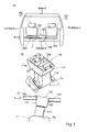
As shown inFIG. 7(A) , in the vehicle collision load transmission structure, aload transmission body 110 is disposed in a position corresponding to a console box (not shown) between adriver seat 101 and apassenger seat 102.
As shown inFIG. 7(B) , theload transmission body 110 is composed of abase portion 114 secured to a vehicle floor F, and aload receiving portion 115 disposed on thebase portion 114. Theload receiving portion 115 is a portion to whichseat rods driver seat 101 and thepassenger seat 102 can contact when a vehicle is hit from a lateral side thereof. Theload receiving portion 115 has a box-shaped member of which the interior portion is segmented and reinforced by a plurality ofvertical walls 115w extending in a vehicle width direction.
Thebase portion 114 is a rigid box-shaped member that is capable of supporting theload receiving portion 115 in the same height as theseat rods driver seat 101 and thepassenger seat 102. Further, thebase portion 114 has leg portions that are formed in four corners thereof and are bolted on an elongated central raised portion Fa of the floor F. -
- Patent Document 1: Japanese Laid-Open Patent Publication No.
2009-126332 - In the above-described
load transmission body 110, theload receiving portion 115 is formed as the box-shaped member, and the interior portion thereof is segmented by a plurality ofvertical walls 115w. Further, thebase portion 114 is also formed as the rigid box-shaped member. That is, both of theload receiving portion 115 and thebase portion 114 of theload transmission body 110 are respectively formed so as to have a high strength. Therefore, as shown inFIG. 7(C) , for example, when a collision load S is applied to theload receiving portion 115 of theload transmission body 110 via theseat rod 102r of thepassenger seat 102, the floor F can be deformed instead of deforming of theload transmission body 110, so that theload transmission body 110 can be tilted toward thedriver seat 101. As a result, theload receiving portion 115 of theload transmission body 110 can be inclined downwardly from a horizontal posture. This may reduce a collision load transmission efficiency between theload transmission body 110 and theseat rods 101r of thedriver seat 101. - The present invention has been made in order to solve problems described above. Accordingly, it is an object of the present invention to prevent a load transmission efficiency from a seat rod of one seat to a seat rod of the other seat from being reduced when a vehicle is hit from a lateral side thereof.
- The above object can be attained by the invention as described in each of the claims.
An invention defined in claim 1 provides a vehicle collision load transmission structure which may include seat rods that are respectively disposed in right and left seats so as to extend in a vehicle width direction, and a load transmission body that is disposed on a vehicle floor so as to be positioned between the seat rods of the right and left seats, in which a collision load applied from a vehicle lateral side can be received by the load transmission body via the seat rod of one of the seats and can be transmitted from the load transmission body to a vehicle side wall positioned opposite to an impact area via the seat rod of the other of the seats, wherein the load transmission body is composed of a base portion that is secured to the vehicle floor, and a load receiving portion that is disposed on the base portion and is constructed such that the seat rods can contact the same, and wherein the base portion is constructed so as to be deformed more easily than the vehicle floor due to application of the collision load in the vehicle width direction. - According to the present invention, the base portion of the load transmission body is constructed so as to be deformed more easily than the vehicle floor due to application of the collision load in the vehicle width direction. Therefore, when the collision load in the vehicle width direction is applied to the load receiving portion of the load transmission body via the seat rod of one of the seats, the base portion of the load transmission body can be deformed in a direction of the collision load while the vehicle floor is not substantially deformed. Thus, because the vehicle floor is not substantially deformed, the load transmission body can be prevented from being tilted. As a result, the load receiving portion disposed on the base portion can be displaced in the direction of the collision load, so as to contact the seat rod of the other of the seats. That is, unlike the conventional structure, the load receiving portion can be prevented from contacting the seat rod of the other of the seats while it is inclined downwardly. Thus, the collision load can be effectively transmitted from the seat rod of one of the seats to the seat rod of the other of the seats.
- In the invention as defined in
claim 2, the base portion is formed as a tunnel-shaped member of which the front and rear sides in a vehicle longitudinal direction are opened.
Therefore, when the collision load in the vehicle width direction is applied to the base portion, the base portion can be easily deformed in the direction of the collision load. - In the invention as defined in
claim 3, the base portion is formed as a press formed article.
Therefore, manufacturing costs of the base portion can be reduced. - According to the present invention, when a vehicle is hit from a lateral side thereof, a load transmission efficiency from a seat rod of one seat to a seat rod of the other seat can be increased.
-
-
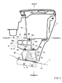
FIG. 1 is a side view of a base portion and a load receiving portion used in a vehicle collision load transmission structure according to Embodiment 1 of the present invention, which view illustrates an assembled condition. -
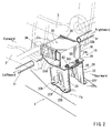
FIG. 2 is a perspective view of the base portion and the load receiving portion used in the vehicle collision load transmission structure, which view illustrates the assembled condition. -
FIG. 3 is a rear view of the base portion and the load receiving portion used in the vehicle collision load transmission structure (a view that is viewed from line III-III ofFIG. 1 ), which view illustrates the assembled condition. -
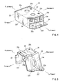
FIG. 4 is a perspective view of the load receiving portion used in the vehicle collision load transmission structure. -
FIG. 5 is a perspective view of the base portion used in the vehicle collision load transmission structure. -
FIG. 6 is a rear view of the base portion and the load receiving portion, which view illustrates a function of the vehicle collision load transmission structure. -
FIG. 7 is a series of views, i.e., a rear view of a base portion and a load receiving portion that constitute a conventional vehicle collision load transmission structure (FIG. 7(A) ), a perspective view of the same (FIG. 7(B) ), and a rear view of the same, which view illustrates a function of the vehicle collision load transmission structure (FIG. 7(C) ). - A vehicle collision load transmission structure according to Embodiment 1 of the present invention will be hereinafter described with reference to
FIGS. 1 to 6 .
Further, forward and backward, rightward and leftward, and upward and downward in the drawings respectively correspond to forward and backward, rightward and leftward, and upward and downward of a vehicle. - The vehicle collision load transmission structure according to the present embodiment is a structure in which a collision load applied from a vehicle lateral side can be received by a
load transmission body 10 via aseat rod 2r of one seat (e.g., apassenger seat 2 shown inFIG. 2 (a chain double-dashed line)) and can be transmitted from theload transmission body 10 to a vehicle side wall positioned opposite to an impact area via aseat rod 3r of the other seat (a driver seat 3). - The
seat rod 3r of thedriver seat 3 is disposed in an interior portion of a seat cushion (not shown) of thedriver seat 3 and is positioned so as to extend in a vehicle width direction. Similarly, theseat rod 2r of thepassenger seat 2 is disposed in an interior portion of a seat cushion (not shown) of thepassenger seat 2 and is positioned so as to extend in the vehicle width direction in the same height as theseat rod 3r of the driver seat 3 (FIGS. 2 and3 ).
As shown inFIG. 1 , theload transmission body 10 is positioned under anarticle storing portion 5s of aconsol box 5. Further, as shown inFIG. 3 , theload transmission body 10 is disposed within an ornamentalouter shell 5k of theconsol box 5. Further, theload transmission body 10 is interposed between theseat rod 3r of thedriver seat 3 and theseat rod 2r of thepassenger seat 2 positioned on both sides thereof in the vehicle width direction without contacting the same.
Further, inFIGS. 2 and3 , in order to clarify a relation among theseat rods load transmission body 10, a distance between themembers members - The
load transmission body 10 is a member that is capable of transmitting the collision load applied from theseat rod 2r of one seat (e.g., the passenger seat 2) to theseat rod 3r of the other seat (e.g., the driver seat 3). As shown inFIG. 1 and other figures, theload transmission body 10 is composed of abase portion 20 that is secured to an elongated central raised portion Fa of a vehicle floor F, and aload receiving portion 30 that is disposed on thebase portion 20 and is capable of receiving the collision load.
Further, the vehicle floor F is formed of, for example, a steel plate having a thickness of 1.2 mm. - The
base portion 20 of theload transmission body 10 is a base member that is capable of horizontally supporting the load receiving portion 30 (which will be hereinafter described) in the same height as theseat rod 3r of thedriver seat 3 and theseat rod 2r of thepassenger seat 2. As shown inFIGS. 2 and5 and other figures, thebase portion 20 is composed of right and leftvertical wall portions 22, and aceiling plate portion 25 that is horizontally bridged between upper end portions of thevertical wall portions 22. That is, thebase portion 20 is formed as a tunnel-shaped member of which the front and rear sides in a vehicle longitudinal direction are opened. Further, the right and leftvertical wall portions 22 respectively have flangedportions 22f that are formed in lower end portions thereof. Each of the flangedportions 22f is formed by folding the lower end portions of thevertical wall portions 22 outwardly over a desired width in the vehicle width direction. The right and leftflanged portions 22f are portions that are connected to the elongated central raised portion Fa of the vehicle floor F. The right and leftflanged portions 22f havebolt insertion holes 22h into which connecting bolts B1 are inserted. Thebolt insertion holes 22h are positioned to be aligned with bolt insertion holes (not shown) that are formed in the elongated central raised portion Fa. Further, the right and leftvertical wall portions 22 of thebase portion 20 respectively have vertically elongatedopenings 22w for strength controlling purposes. Each of theopenings 22w is formed in a central portion of each of thevertical wall portions 22.
Theceiling plate portion 25 of thebase portion 20 has a rectangular table shape. Further, theceiling plate portion 25 hasbolt insertion holes 25h that are formed in four corner portions thereof, i.e., front and rear and right and left corner portions thereof, so that the load receiving portion 30 (which will be hereinafter described) can be bolted on theceiling plate portion 25.
Thebase portion 20 is formed by, for example, press forming a steel plate (2.0 mm). Further, as previously described, thebase portion 20 is formed as the tunnel-shaped member of which the front and rear sides are opened. Therefore, thebase portion 20 can be deformed in a direction of the collision load more easily than the vehicle floor F (the steel plate having the 1.2 mm thickness) due to application of the collision load in the vehicle width direction. In addition, thebase portion 20 can be reduced in weight because the front and rear sides thereof are opened, i.e., because no wall portions are present in the front and rear sides thereof. - The
load receiving portion 30 of theload transmission body 10 is a portion to which end portions of theseat rods driver seat 3 and thepassenger seat 2 can contact with interleaving the ornamentalouter shell 5k of theconsol box 5 when the vehicle is hit from a lateral side thereof. As shown inFIG. 3 , theload receiving portion 30 has a width greater than thebase portion 20, so that right and left end portions thereof can be projected in the vehicle width direction beyond right and left end portions of the base portion. As a result, a distance between theseat rod 3r of thedriver seat 3 and theload receiving portion 30 and a distance between theseat rod 2r of thepassenger seat 2 and theload receiving portion 30 can be reduced as much as possible.
As shown inFIG. 4 and other figures, theload receiving portion 30 is composed of a receiving portionmain body 32 having a rectangular cylindrical shape, aflange portion 34 projected rearwardly from a rear end periphery of a lower end portion of the receiving portionmain body 32 and having a constant width, and a pair of side plate portions 36 (FIG. 2 and other figures) covering a right end face and a left end face of the receiving portionmain body 32. - As shown in
FIG. 4 and other figures, the receiving portionmain body 32 of theload receiving portion 30 is constructed of afront plate portion 33f, anupper plate portion 33u, alower plate portion 33d and arear plate portion 33b, so as to have the rectangular cylindrical shape that extends in the vehicle width direction. An interior portion of the receiving portionmain body 32 is vertically separated by a transversepartition plate portion 32m, so as to have upper and lower cavities. Further, the upper cavity formed in the receiving portionmain body 32 by the transversepartition plate portion 32m is segmented at regular intervals by two verticalpartition plate portions 32w that extend in the vehicle width direction. Further, as shown inFIG. 1 , theseat rod 3r and theseat rod 2r are positioned such that the load applied therefrom can be received in an intersection portion of the transversepartition plate portion 32m and a front side one of the verticalpartition plate portions 32w of the receiving portionmain body 32.
Thus, due to the verticalpartition plate portions 32w and the transversepartition plate portion 32m, theload receiving portion 30 may have a desired strength that is required to bear the collision load S in the vehicle width direction.
As shown inFIGS. 1 and2 , a substantially rear half portion of thelower plate portion 33d of the receiving portionmain body 32 is formed as a flattened portion, so as to be seated on theceiling plate portion 25 of thebase portion 20. Further, theflange portion 34 of theload receiving portion 30 is formed as an extension of the flattened portion of thelower plate portion 33d. Further, a substantially front half portion of thelower plate portion 33d is inclined upwardly and forwardly - The
lower plate portion 33d of the receiving portionmain body 32 and theflange portion 34 respectively havebolt insertion holes FIGS. 2 and4 ) into which connecting bolts B3 (FIG. 1 ) are inserted. Thebolt insertion holes bolt insertion holes 25h formed in theceiling plate portion 25 of thebase portion 20.
Further, as shown inFIGS. 1 and4 and other figures, theupper plate portion 33u of the receiving portionmain body 32 has bolt insertion holes 32x that are formed in right and left portions of a rear portion thereof, so that the receiving portionmain body 32 can be bolted on thearticle storing portion 5s of theconsol box 5.
The receiving portionmain body 32 and theflange portion 34 of theload receiving portion 30 are constructed of an aluminum plate having a thickness of 2 mm.
Further, as shown inFIG. 2 and other figures, each of the pair ofside plate portions 36 covering the right end face and the left end face of the receiving portionmain body 32 has a rectangular shape that extends in the vehicle longitudinal direction and has a size that is capable of covering an area in which theseat rod - First, as shown in
FIG. 2 , thebolt insertion holes 22h of theflanged portions 22f of thebase portion 20 are aligned with the bolt insertion holes (not shown) of the elongated central raised portion Fa of the vehicle floor F, so that thebase portion 20 can be secured to the vehicle floor using the connecting bolts B1 (FIG. 1 ). In this condition, theceiling plate portion 25 of thebase portion 20 can be held horizontally.
Next, thebolt insertion holes main body 32 and theflange portion 34 of theload receiving portion 30 are aligned with thebolt insertion holes 25h formed in theceiling plate portion 25 of thebase portion 20, so that theload receiving portion 30 can be secured to theceiling plate portion 25 of thebase portion 20 using the connecting bolts B3 (FIGS. 1 and2 and other figures).
Next, as shown inFIG. 1 , bolt insertion holes (not shown) of thearticle storing portion 5s of theconsol box 5 are aligned with thebolt insertion holes 32x of theupper plate portion 33u of theload receiving portion 30, so that thearticle storing portion 5s can be secured to theupper plate portion 33u of theload receiving portion 30 using connecting bolts B4. At this time, theload transmission body 10 and thearticle storing portion 5s can be covered by the ornamentalouter shell 5k of theconsol box 5. - As shown in, for example,
FIGS. 7(A) and6 , in the vehicle collision load transmission structure of the present embodiment, when the collision load S is applied from left of the vehicle, a left center pillar (not shown) is pressed into a vehicle cabin due to the collision load S, so that thepassenger seat 2 is pressed toward thedriver seat 3. As a result, the collision load S can be transmitted to theload receiving portion 30 of theload transmission body 10 via theseat rod 2r of thepassenger seat 2.
When the collision load S is applied to theload receiving portion 30 from theseat rod 2r of thepassenger seat 2, the collision load S can be applied to thebase portion 20 supporting theload receiving portion 30 via theload receiving portion 30. As previously described, thebase portion 20 is formed as the tunnel-shaped member of which the front and rear sides are opened, so as to be easily deformed compared with the vehicle floor F due to application of the collision load S. Therefore, as shown inFIG. 6 , when the collision load S is applied to thebase portion 20, only thebase portion 20 can be deformed in the direction of the collision load S while the vehicle floor F is not substantially deformed, so that theload receiving portion 30 supported by thebase portion 20 moves in the direction of the collision load S. That is, theload transmission body 10 can be prevented from being tilted, so that theload receiving portion 30 can contact theseat rod 3r of thedrive seat 3 while moving in the direction of the collision load S. As a result, the collision load S can effectively be transmitted from theseat rod 2r of thepassenger seat 2 to theseat rod 3r of thedrive seat 3 via theload transmission body 10, and then be transmitted to a right center pillar (not shown). - According to the vehicle collision load transmission structure of the present embodiment, the
base portion 20 of theload transmission body 10 is constructed so as to be deformed in the direction of the collision load S more easily than the vehicle floor F due to application of the collision load S in the vehicle width direction. Therefore, when the collision load S in the vehicle width direction is applied to theload receiving portion 30 of theload transmission body 10 via theseat rod 2r of thepassenger seat 2, thebase portion 20 of theload transmission body 10 can be deformed in the direction of the collision load S while the vehicle floor F is not substantially deformed. Thus, because the vehicle floor F is not substantially deformed, theload transmission body 10 can be prevented from being tilted. As a result, theload receiving portion 30 disposed on thebase portion 20 can be displaced in the direction of the collision load S, so as to contact theseat rod 3r of thedrive seat 3. That is, unlike the conventional structure, theload receiving portion 30 can be prevented from contacting theseat rod 3r of thedrive seat 3 while it is inclined downwardly. Thus, the collision load S can be effectively transmitted from theseat rod 2r of thepassenger seat 2 to theseat rod 3r of thedrive seat 3.
Further, thebase portion 20 is formed as the tunnel-shaped member of which the front and rear sides in the vehicle longitudinal direction are opened. Therefore, when the collision load S in the vehicle width direction is applied to thebase portion 20, thebase portion 20 can be easily deformed in the direction of the collision load S.
In addition, because thebase portion 20 is formed as a press formed article, manufacturing costs thereof can be reduced. - Further, the present invention is not limited to the embodiment described above, and the embodiment can be easily changed or modified without departing from the scope of the present invention. For example, in the present embodiment, the
base portion 20 of theload transmission body 10 is formed by press forming the steel plate. However, thebase portion 20 can be formed of resins, aluminum or other such materials.
Further, in the present embodiment, theload receiving portion 30 of theload transmission body 10 is formed of the aluminum plate. However, theload receiving portion 30 can be formed of resins, the steel plate or other such materials.
In addition, a thickness of each of theload receiving portion 30 and thebase portion 20 of theload transmission body 10 can be appropriately changed as necessary. -
- 2r...seat rod
- 2...passenger seat
- 3r...seat rod
- 3...drive seat
- 10...load transmission body
- 20...base portion
- 22...vertical wall portion
- 25...ceiling plate portion
- 30...load receiving portion
- F...vehicle floor
- Fa...elongated central raised portion
- S...collision load
Claims (3)
- A vehicle collision load transmission structure comprising seat rods that are respectively disposed in right and left seats so as to extend in a vehicle width direction, and a load transmission body that is disposed on a vehicle floor so as to be positioned between the seat rods of the right and left seats, in which a collision load applied from a vehicle lateral side can be received by the load transmission body via the seat rod of one of the seats and can be transmitted from the load transmission body to a vehicle side wall positioned opposite to an impact area via the seat rod of the other of the seats,
wherein the load transmission body is composed of a base portion that is secured to the vehicle floor, and a load receiving portion that is disposed on the base portion and is constructed such that the seat rods can contact the same, and
wherein the base portion is constructed so as to be deformed more easily than the vehicle floor due to application of the collision load in the vehicle width direction. - The vehicle collision load transmission structure as defined in claim 1, wherein the base portion is formed as a tunnel-shaped member of which the front and rear sides in a vehicle longitudinal direction are opened.
- The vehicle collision load transmission structure as defined in claim 2, wherein the base portion is formed as a press formed article.
Applications Claiming Priority (2)
| Application Number | Priority Date | Filing Date | Title |
|---|---|---|---|
| JP2010025410A JP5299305B2 (en) | 2010-02-08 | 2010-02-08 | Vehicle collision load transmission structure |
| PCT/JP2011/050325 WO2011096253A1 (en) | 2010-02-08 | 2011-01-12 | Vehicle collision load transmission structure |
Publications (2)
| Publication Number | Publication Date |
|---|---|
| EP2535244A1 true EP2535244A1 (en) | 2012-12-19 |
| EP2535244A4 EP2535244A4 (en) | 2014-04-30 |
Family
ID=44355263
Family Applications (1)
| Application Number | Title | Priority Date | Filing Date |
|---|---|---|---|
| EP11739602.8A Withdrawn EP2535244A4 (en) | 2010-02-08 | 2011-01-12 | Vehicle collision load transmission structure |
Country Status (4)
| Country | Link |
|---|---|
| US (1) | US20120292947A1 (en) |
| EP (1) | EP2535244A4 (en) |
| JP (1) | JP5299305B2 (en) |
| WO (1) | WO2011096253A1 (en) |
Cited By (1)
| Publication number | Priority date | Publication date | Assignee | Title |
|---|---|---|---|---|
| CN104786947A (en) * | 2015-04-30 | 2015-07-22 | 重庆长安汽车股份有限公司 | Connection structure of vehicle armrest box and floor assembly |
Families Citing this family (3)
| Publication number | Priority date | Publication date | Assignee | Title |
|---|---|---|---|---|
| US9873382B1 (en) * | 2016-07-01 | 2018-01-23 | Toyota Motor Engineering & Manufacturing North America, Inc. | Console assemblies having support structures with side impact reinforcements |
| JP7167823B2 (en) | 2019-04-04 | 2022-11-09 | 株式会社豊田自動織機 | console support structure |
| JP7779942B2 (en) * | 2024-03-15 | 2025-12-03 | 本田技研工業株式会社 | Console box structure |
Family Cites Families (10)
| Publication number | Priority date | Publication date | Assignee | Title |
|---|---|---|---|---|
| JP4848857B2 (en) * | 2006-06-23 | 2011-12-28 | トヨタ車体株式会社 | Car cabin floor |
| JP2009035094A (en) * | 2007-08-01 | 2009-02-19 | Toyota Motor Corp | Energy absorption structure for battery mounting |
| JP2009126332A (en) * | 2007-11-22 | 2009-06-11 | Toyota Auto Body Co Ltd | Vehicle structure |
| JP5172325B2 (en) * | 2007-12-28 | 2013-03-27 | 本田技研工業株式会社 | Load transmission structure between vehicle seats |
| JP5075743B2 (en) * | 2008-06-10 | 2012-11-21 | アイシン精機株式会社 | Floor tunnel box |
| JP4485582B2 (en) * | 2008-07-11 | 2010-06-23 | 本田技研工業株式会社 | Vehicle load transmission |
| JP4690450B2 (en) * | 2008-12-19 | 2011-06-01 | 本田技研工業株式会社 | Body floor structure |
| JP4914906B2 (en) * | 2009-03-25 | 2012-04-11 | 本田技研工業株式会社 | Body structure |
| JP4738506B2 (en) * | 2009-03-26 | 2011-08-03 | 本田技研工業株式会社 | Reinforcement structure |
| JP2010274802A (en) * | 2009-05-28 | 2010-12-09 | Kanto Auto Works Ltd | Collision resistant structure |
-
2010
- 2010-02-08 JP JP2010025410A patent/JP5299305B2/en active Active
-
2011
- 2011-01-12 US US13/576,132 patent/US20120292947A1/en not_active Abandoned
- 2011-01-12 EP EP11739602.8A patent/EP2535244A4/en not_active Withdrawn
- 2011-01-12 WO PCT/JP2011/050325 patent/WO2011096253A1/en not_active Ceased
Cited By (1)
| Publication number | Priority date | Publication date | Assignee | Title |
|---|---|---|---|---|
| CN104786947A (en) * | 2015-04-30 | 2015-07-22 | 重庆长安汽车股份有限公司 | Connection structure of vehicle armrest box and floor assembly |
Also Published As
| Publication number | Publication date |
|---|---|
| US20120292947A1 (en) | 2012-11-22 |
| JP5299305B2 (en) | 2013-09-25 |
| JP2011162003A (en) | 2011-08-25 |
| EP2535244A4 (en) | 2014-04-30 |
| WO2011096253A1 (en) | 2011-08-11 |
Similar Documents
| Publication | Publication Date | Title |
|---|---|---|
| US8132852B2 (en) | Vehicle body structure | |
| US8333425B2 (en) | Vehicle front structure | |
| US11565578B2 (en) | Vehicle front portion structure | |
| CN111469935B (en) | The rear body structure of the vehicle | |
| US7185934B2 (en) | Vehicle body structure | |
| CN102791566B (en) | Structure for front section of vehicle body | |
| US20180126835A1 (en) | Vehicle lower section structure | |
| CN109228838A (en) | Automobile | |
| WO2008047749A1 (en) | Floor underframe for vehicle | |
| CN104943522A (en) | Protective structure of battery module carried on rear part of vehicle body | |
| US20130049394A1 (en) | Automotive rear body structure | |
| CN108859747A (en) | Vehicle | |
| JP2007038839A (en) | Rear body structure of automobile | |
| CN101844551A (en) | Reinforcing element structure | |
| CN108001540B (en) | Lower vehicle body frame and vehicle with same | |
| KR20120082908A (en) | One-piece seat bottom chassis | |
| KR101526397B1 (en) | Structure for reinforcing seat mounting portion of vehicle body | |
| JP2023029583A (en) | car body structural member | |
| CN107097855A (en) | Battery fixing structure | |
| CN104290822A (en) | Substructure for a motor vehicle | |
| CN109204540B (en) | Vehicle body structure and vehicle | |
| US20120292947A1 (en) | Vehicle collision load transmission structure | |
| CN215904613U (en) | Rear floor framework of automobile | |
| CN106184384B (en) | Vehicle body reinforcing structure | |
| JP2016078658A (en) | Lower body structure of the vehicle |
Legal Events
| Date | Code | Title | Description |
|---|---|---|---|
| PUAI | Public reference made under article 153(3) epc to a published international application that has entered the european phase |
Free format text: ORIGINAL CODE: 0009012 |
|
| 17P | Request for examination filed |
Effective date: 20120725 |
|
| AK | Designated contracting states |
Kind code of ref document: A1 Designated state(s): AL AT BE BG CH CY CZ DE DK EE ES FI FR GB GR HR HU IE IS IT LI LT LU LV MC MK MT NL NO PL PT RO RS SE SI SK SM TR |
|
| DAX | Request for extension of the european patent (deleted) | ||
| A4 | Supplementary search report drawn up and despatched |
Effective date: 20140401 |
|
| RIC1 | Information provided on ipc code assigned before grant |
Ipc: B60R 7/04 20060101ALI20140326BHEP Ipc: B62D 25/20 20060101AFI20140326BHEP Ipc: B60N 2/42 20060101ALI20140326BHEP |
|
| 17Q | First examination report despatched |
Effective date: 20150302 |
|
| GRAP | Despatch of communication of intention to grant a patent |
Free format text: ORIGINAL CODE: EPIDOSNIGR1 |
|
| INTG | Intention to grant announced |
Effective date: 20151118 |
|
| STAA | Information on the status of an ep patent application or granted ep patent |
Free format text: STATUS: THE APPLICATION IS DEEMED TO BE WITHDRAWN |
|
| 18D | Application deemed to be withdrawn |
Effective date: 20160330 |