EP2534977A1 - Engaging mechanism of closing device - Google Patents
Engaging mechanism of closing device Download PDFInfo
- Publication number
- EP2534977A1 EP2534977A1 EP11169789A EP11169789A EP2534977A1 EP 2534977 A1 EP2534977 A1 EP 2534977A1 EP 11169789 A EP11169789 A EP 11169789A EP 11169789 A EP11169789 A EP 11169789A EP 2534977 A1 EP2534977 A1 EP 2534977A1
- Authority
- EP
- European Patent Office
- Prior art keywords
- contact surface
- stop
- positioning hook
- engaging
- engaging block
- Prior art date
- Legal status (The legal status is an assumption and is not a legal conclusion. Google has not performed a legal analysis and makes no representation as to the accuracy of the status listed.)
- Granted
Links
Images



Classifications
-
- E—FIXED CONSTRUCTIONS
- E05—LOCKS; KEYS; WINDOW OR DOOR FITTINGS; SAFES
- E05B—LOCKS; ACCESSORIES THEREFOR; HANDCUFFS
- E05B65/00—Locks or fastenings for special use
- E05B65/46—Locks or fastenings for special use for drawers
-
- A—HUMAN NECESSITIES
- A47—FURNITURE; DOMESTIC ARTICLES OR APPLIANCES; COFFEE MILLS; SPICE MILLS; SUCTION CLEANERS IN GENERAL
- A47B—TABLES; DESKS; OFFICE FURNITURE; CABINETS; DRAWERS; GENERAL DETAILS OF FURNITURE
- A47B88/00—Drawers for tables, cabinets or like furniture; Guides for drawers
- A47B88/40—Sliding drawers; Slides or guides therefor
- A47B88/453—Actuated drawers
- A47B88/46—Actuated drawers operated by mechanically-stored energy, e.g. by springs
- A47B88/467—Actuated drawers operated by mechanically-stored energy, e.g. by springs self-closing
-
- E—FIXED CONSTRUCTIONS
- E05—LOCKS; KEYS; WINDOW OR DOOR FITTINGS; SAFES
- E05C—BOLTS OR FASTENING DEVICES FOR WINGS, SPECIALLY FOR DOORS OR WINDOWS
- E05C19/00—Other devices specially designed for securing wings, e.g. with suction cups
- E05C19/02—Automatic catches, i.e. released by pull or pressure on the wing
- E05C19/022—Released by pushing in the closing direction
Definitions
- the present invention relates to an engaging mechanism of a closing device, and more particularly, to an engaging mechanism for a closing device between two pieces of furniture so that when any one of the two pieces is improperly opened, the closing device is protected.
- U.S. Patent No. 5,040,833 to Brunnert discloses a "closing device for drawers" includes a drawer installed to a piece of furniture and the drawer is movable between a closed position and an opened position on the piece of furniture.
- a spring is located between the drawer and the piece of the furniture.
- a closing device is connected to the piece of the furniture and includes a holding member 9 which has a hook-shaped end 9'.
- a latch member 11 is connected to the drawer and is a board with two raised areas 12, 13, wherein the raised area 12 defines a notch 14. When the drawer is located at the closed position, the notch is engaged with the hook-shaped end of the holding member. Furthermore, the two raised areas define at least two different guide tracks which guide the holding member.
- the holding member When the drawer is movable between the closed and opened positions, the holding member is guided by the two different guide tracks and bent. When the drawer is pulled out from the piece of the furniture improperly, the deformation of the holding member makes the hook-shaped end be disengaged from the notch.
- the above-mentioned is a closing device for a drawer and the correct way of use is to push the drawer to open the drawer. If an improper force is applied to the drawer, such as to pull the drawer outward, although the hook-shaped end of the holding member can be disengaged from the notch, the notch of the holding member is scraped by the hook-shaped end of the holding member, so that the notch and the holding ember both are worn after several times of this type of operation. The holding member tends to be disengaged from the notch frequently and the positioning feature fails.
- the present invention intends to provide an improved design to overcome the shortcomings mentioned above.
- the present invention relates to an engaging mechanism of a closing device, and more particularly, to an engaging mechanism for a closing device between two pieces of furniture.
- the engaging mechanism includes a contact surface which is cooperated with a stop of a positioning hook and a resilient portion of the positioning hook to make a part firmly contact the contact surface.
- the stop is disengaged from the contact surface by the deformation of the resilient portion.
- the engaging mechanism of a closing device and comprises an engaging block which has a contact surface and a guide surface extending from the contact surface.
- a positioning hook is connected to the engaging block and has a resilient portion and a stop which extends from the resilient portion.
- the stop is located adjacent to the contact surface and located at a distance from the guide surface.
- a pin is located corresponding to the engaging block and slidably contacts the contact surface and the stop of the positioning hook. The pin moves over the stop and is disengaged from the contact surface by contacting against the stop and by the deformation of the resilient portion.
- the positioning hook integrally extends from the engaging block.
- a buffering space is defined beside the positioning hook and the resilient portion of the positioning hook is operated within the buffering space.
- the engaging block has a slot and the positioning hook is connected to an insertion to form an independent part.
- a buffering space is defined between the positioning hook and the insertion. The insertion is inserted into the slot and is connected to the engaging block.
- a groove communicates with the slot.
- the insertion has a protrusion. The insertion is engaged with the slot when the protrusion is engaged with the groove.
- the insertion has an opening defined by two legs, and at least one of the legs has a boss.
- the engaging mechanism of a closing device of the present invention comprises an engaging block 10, a positioning hook 12 and a pin 14.
- the engaging block 10 comprises a contact surface 16 and a guide surface 18 extending from the contact surface 16.
- the positioning hook 12 is connected to the engaging block 10 and comprises a resilient portion 20 and a stop 22 which extends from the resilient portion 20.
- the stop 22 is located adjacent to the contact surface 16 and located at a distance from the guide surface 18.
- the pin 14 is located corresponding to the engaging block 10 and slidably contacts the contact surface 16 and the stop 22 of the positioning hook 12.
- the engaging block 10 is located on a contact member 24 which includes a guide path 26 defined around the engaging block 10, and a guide block 28 which is located corresponding to the contact surface 16 of the engaging block 10 and the positioning hook 12.
- the guide path 26 and the guide block 28 are used to guide the pin 14 to contact the engaging block 10, or to guide the pin 14 to disengage from the engaging block 10.
- the positioning hook 12 integrally extends from the engaging block 10.
- a buffering space 30 is defined beside the positioning hook 12 and the resilient portion 20 of the positioning hook 12 is operated within the buffering space 30.
- Figs. 3 and 4 show the second embodiment of the present invention, wherein the engaging block 200 has a slot 202 and the positioning hook 204 is connected to an insertion 206 to form an independent part.
- a buffering space 208 is defined between the positioning hook 204 and the insertion 206.
- the insertion 206 is inserted into the slot 202 and is connected to the engaging block 200.
- a groove 210 communicates with the slot 202.
- the insertion 206 has a protrusion 212. The insertion 206 is engaged with the slot 202 when the protrusion 212 is engaged with the groove 210, so that the positioning hook 204 is selectively connected to the engaging block 200 to correct the positioning hook 204 and the engaging block 200.
- the insertion 206 has an opening 214 defined in a distal end thereof and the opening 214 is defined by two legs 216. At least one of the legs 216 has a boss 218.
- the slot 202 of the engaging block 200 has a notch 220 which is located corresponding to the boss 218, as shown in Figs. 5 and 6 .
- the boss 218 of the leg 216 is engaged with the notch 220 to firmly insert the insertion 206 of the positioning hook 204 into the slot 202.
- the engaging block 200 is connected on the contact member 222 and has a contact surface 224.
- the contact member 222 has a guide path 226 defined around the engaging block 200, and a guide block 228 which is located corresponding to the contact surface 224 of the engaging block 200 and the positioning hook 204.
- the positioning hook 204 has a resilient portion 232 and a stop 234 extends from the resilient portion 232.
- the present invention is applied to a fixed part and a movable part of furniture, for example, the fixed part is a cabinet or a fixed rail, and the movable part is a drawer or a movable rail.
- the cabinet and the drawer Taken the cabinet and the drawer as an example, the contact member 24(222) of the engaging block 10(200) is fixed to the cabinet and the pin 14(230) is movably connected to the drawer with the contact member 24(222) by guidance of the guide path 26(226).
- the pin 24(230) contacts the contact surface 16(224) of the engaging block 10(200), and by the contact of the stop 22(234) of the positioning hook 12(204), the drawer is kept at the closed position.
- the pin 14(230) When the drawer is pushed toward the cabinet, the pin 14(230) is guided by the guide block 28(228) and disengaged from the contact surface 16(224) of the engaging block 10(200). The drawer is then freely pulled out from the cabinet. When the drawer is pulled by an improper force, the pin 14(230) is disengaged from the contact surface 16(224) of the engaging block 10(200), while the stop 22(234) of the positioning hook 12(204) is not damaged and the positioning feature does not fail.
Landscapes
- Engineering & Computer Science (AREA)
- Mechanical Engineering (AREA)
- Drawers Of Furniture (AREA)
Abstract
Description
- The present invention relates to an engaging mechanism of a closing device, and more particularly, to an engaging mechanism for a closing device between two pieces of furniture so that when any one of the two pieces is improperly opened, the closing device is protected.
-
U.S. Patent No. 5,040,833 to Brunnert discloses a "closing device for drawers" includes a drawer installed to a piece of furniture and the drawer is movable between a closed position and an opened position on the piece of furniture. A spring is located between the drawer and the piece of the furniture. A closing device is connected to the piece of the furniture and includes a holding member 9 which has a hook-shaped end 9'. A latch member 11 is connected to the drawer and is a board with two raisedareas 12, 13, wherein the raisedarea 12 defines anotch 14. When the drawer is located at the closed position, the notch is engaged with the hook-shaped end of the holding member. Furthermore, the two raised areas define at least two different guide tracks which guide the holding member. When the drawer is movable between the closed and opened positions, the holding member is guided by the two different guide tracks and bent. When the drawer is pulled out from the piece of the furniture improperly, the deformation of the holding member makes the hook-shaped end be disengaged from the notch. - When a force pushes the drawer which is at its closed position, the hook-shaped end of the holding member is movable and disengaged from the latch member so that the drawer pops out from the piece of the furniture in response to the force generated by the spring.
- The above-mentioned is a closing device for a drawer and the correct way of use is to push the drawer to open the drawer. If an improper force is applied to the drawer, such as to pull the drawer outward, although the hook-shaped end of the holding member can be disengaged from the notch, the notch of the holding member is scraped by the hook-shaped end of the holding member, so that the notch and the holding ember both are worn after several times of this type of operation. The holding member tends to be disengaged from the notch frequently and the positioning feature fails.
- The present invention intends to provide an improved design to overcome the shortcomings mentioned above.
- The present invention relates to an engaging mechanism of a closing device, and more particularly, to an engaging mechanism for a closing device between two pieces of furniture. The engaging mechanism includes a contact surface which is cooperated with a stop of a positioning hook and a resilient portion of the positioning hook to make a part firmly contact the contact surface. When the part is applied by a force, the part contacts against the contact surface and the stop, the stop is disengaged from the contact surface by the deformation of the resilient portion.
- The engaging mechanism of a closing device and comprises an engaging block which has a contact surface and a guide surface extending from the contact surface. A positioning hook is connected to the engaging block and has a resilient portion and a stop which extends from the resilient portion. The stop is located adjacent to the contact surface and located at a distance from the guide surface. A pin is located corresponding to the engaging block and slidably contacts the contact surface and the stop of the positioning hook. The pin moves over the stop and is disengaged from the contact surface by contacting against the stop and by the deformation of the resilient portion.
- Preferably, the positioning hook integrally extends from the engaging block.
- Preferably, a buffering space is defined beside the positioning hook and the resilient portion of the positioning hook is operated within the buffering space.
- Preferably, the engaging block has a slot and the positioning hook is connected to an insertion to form an independent part. A buffering space is defined between the positioning hook and the insertion. The insertion is inserted into the slot and is connected to the engaging block.
- Preferably, a groove communicates with the slot. The insertion has a protrusion. The insertion is engaged with the slot when the protrusion is engaged with the groove.
- Preferably, the insertion has an opening defined by two legs, and at least one of the legs has a boss.
- The present invention will become more obvious from the following description when taken in connection with the accompanying drawings which show, for purposes of illustration only, a preferred embodiment in accordance with the present invention.
-
-
Fig. 1 shows a part of the engaging block and the pin of the engaging mechanism of the present invention; -
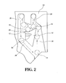
Fig. 2 shows the movement of the pin in the guide path of the contact member of the engaging mechanism of the present invention; -
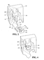
Fig. 3 shows a part the engaging block and the pin of the second embodiment of the engaging mechanism of the present invention; -
Fig. 4 is a perspective view to show the second embodiment of the engaging mechanism of the present invention; -
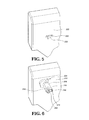
Fig. 5 shows the slot in the engaging block of the second embodiment of the engaging mechanism of the present invention; -
Fig. 6 shows that the positioning hook is inserted into the slot of the engaging block of the second embodiment of the engaging mechanism of the present invention; -
Fig. 7 shows that the pin contacts the contact surface of the engaging block via the guide path of the second embodiment of the engaging mechanism of the present invention, and -
Fig. 8 shows that when a force pushes the pin toward the engaging block of the second embodiment, the pin is disengaged from the contact surface of the engaging block. - Referring to
Figs. 1 and2 , the engaging mechanism of a closing device of the present invention comprises anengaging block 10, apositioning hook 12 and apin 14. - The
engaging block 10 comprises acontact surface 16 and aguide surface 18 extending from thecontact surface 16. Thepositioning hook 12 is connected to theengaging block 10 and comprises aresilient portion 20 and astop 22 which extends from theresilient portion 20. Thestop 22 is located adjacent to thecontact surface 16 and located at a distance from theguide surface 18. Thepin 14 is located corresponding to theengaging block 10 and slidably contacts thecontact surface 16 and thestop 22 of thepositioning hook 12. - In this embodiment, the
engaging block 10 is located on acontact member 24 which includes aguide path 26 defined around theengaging block 10, and aguide block 28 which is located corresponding to thecontact surface 16 of theengaging block 10 and thepositioning hook 12. When thecontact member 24 and thepin 14 have relative movement, theguide path 26 and theguide block 28 are used to guide thepin 14 to contact theengaging block 10, or to guide thepin 14 to disengage from theengaging block 10. - In this embodiment, the
positioning hook 12 integrally extends from theengaging block 10. - In this embodiment, a
buffering space 30 is defined beside thepositioning hook 12 and theresilient portion 20 of thepositioning hook 12 is operated within thebuffering space 30. -
Figs. 3 and 4 show the second embodiment of the present invention, wherein theengaging block 200 has aslot 202 and thepositioning hook 204 is connected to aninsertion 206 to form an independent part. Abuffering space 208 is defined between thepositioning hook 204 and theinsertion 206. Theinsertion 206 is inserted into theslot 202 and is connected to theengaging block 200. Agroove 210 communicates with theslot 202. Theinsertion 206 has aprotrusion 212. Theinsertion 206 is engaged with theslot 202 when theprotrusion 212 is engaged with thegroove 210, so that thepositioning hook 204 is selectively connected to theengaging block 200 to correct thepositioning hook 204 and theengaging block 200. For convenience of assembling and secured, theinsertion 206 has anopening 214 defined in a distal end thereof and theopening 214 is defined by twolegs 216. At least one of thelegs 216 has aboss 218. Theslot 202 of theengaging block 200 has anotch 220 which is located corresponding to theboss 218, as shown inFigs. 5 and 6 . Theboss 218 of theleg 216 is engaged with thenotch 220 to firmly insert theinsertion 206 of thepositioning hook 204 into theslot 202. - In the second embodiment, the
engaging block 200 is connected on thecontact member 222 and has acontact surface 224. Thecontact member 222 has aguide path 226 defined around the engagingblock 200, and aguide block 228 which is located corresponding to thecontact surface 224 of theengaging block 200 and thepositioning hook 204. Thepositioning hook 204 has aresilient portion 232 and astop 234 extends from theresilient portion 232. - As shown in
Fig. 7 , taken the second embodiment as an example, when thecontact member 222 and thepin 230 have relative movement, thepin 230 is guided by theguide path 226 to contact thecontact surface 224 of theengaging block 200 and thepin 230 is stopped by thestop 234 of thepositioning hook 204. Thepin 230 stays at the contact position and does not disengage from the contact position. - When a force pushes the
pin 230 toward theengaging block 200, as shown inFig. 8 , thepin 230 moves over thecontact surface 224 and pushes thestop 234 of thepositioning hook 204. By the deformation of theresilient portion 232, thestop 234 is pushed by thepin 230 and thepin 230 moves over thestop 234 and is disengaged from thecontact surface 224. - The present invention is applied to a fixed part and a movable part of furniture, for example, the fixed part is a cabinet or a fixed rail, and the movable part is a drawer or a movable rail. Taken the cabinet and the drawer as an example, the contact member 24(222) of the engaging block 10(200) is fixed to the cabinet and the pin 14(230) is movably connected to the drawer with the contact member 24(222) by guidance of the guide path 26(226). When the drawer is pushed into the cabinet, the pin 24(230) contacts the contact surface 16(224) of the engaging block 10(200), and by the contact of the stop 22(234) of the positioning hook 12(204), the drawer is kept at the closed position. When the drawer is pushed toward the cabinet, the pin 14(230) is guided by the guide block 28(228) and disengaged from the contact surface 16(224) of the engaging block 10(200). The drawer is then freely pulled out from the cabinet. When the drawer is pulled by an improper force, the pin 14(230) is disengaged from the contact surface 16(224) of the engaging block 10(200), while the stop 22(234) of the positioning hook 12(204) is not damaged and the positioning feature does not fail.
- While we have shown and described the embodiment in accordance with the present invention, it should be clear to those skilled in the art that further embodiments may be made without departing from the scope of the present invention.
Claims (6)
- An engaging mechanism of a closing device, characterized in that the engaging mechanism comprises:an engaging block (10) having a contact surface (16) and a guide surface (18) extending from the contact surface (16);a positioning hook (12) connected to the engaging block (10) and having a resilient portion (20) and a stop (22) which extends from the resilient portion (20), the stop (22) located adjacent to the contact surface (16) and located at a distance from the guide surface (18), anda pin (14) located corresponding to the engaging block (10) and slidably contacting the contact surface (16) and the stop (22) of the positioning hook (12), the pin (14) moving over the stop (22) and disengaged from the contact surface (16) by contacting against the stop (22) and deformation of the resilient portion (20).
- The engaging mechanism as claimed in claim 1, wherein the positioning hook (12) integrally extends from the engaging block (10).
- The engaging mechanism as claimed in claim 2, wherein a buffering space (30) is defined beside the positioning hook (12) and the resilient portion (20) of the positioning hook (12) is operated within the buffering space (30).
- The engaging mechanism as claimed in claim 1, wherein the engaging block (200) has a slot (202) and the positioning hook (204) is connected to an insertion (206) to form an independent part, a buffering space (208) is defined between the positioning hook (204) and the insertion (206), the insertion (206) is inserted into the slot (202) and is connected to the engaging block (200).
- The engaging mechanism as claimed in claim 4, wherein a groove (210) communicates with the slot (202), the insertion (206) has a protrusion (212), the insertion (206) is engaged with the slot (202) when the protrusion (212) is engaged with the groove (210).
- The engaging mechanism as claimed in claim 4, wherein the insertion (206) has an opening (214) defined by two legs (216), at least one of the legs (216) has a boss (218).
Priority Applications (2)
| Application Number | Priority Date | Filing Date | Title |
|---|---|---|---|
| ES11169789.2T ES2524417T3 (en) | 2011-06-14 | 2011-06-14 | Closing device gear mechanism |
| EP11169789.2A EP2534977B1 (en) | 2011-06-14 | 2011-06-14 | Engaging mechanism of closing device |
Applications Claiming Priority (1)
| Application Number | Priority Date | Filing Date | Title |
|---|---|---|---|
| EP11169789.2A EP2534977B1 (en) | 2011-06-14 | 2011-06-14 | Engaging mechanism of closing device |
Publications (2)
| Publication Number | Publication Date |
|---|---|
| EP2534977A1 true EP2534977A1 (en) | 2012-12-19 |
| EP2534977B1 EP2534977B1 (en) | 2014-09-17 |
Family
ID=44801249
Family Applications (1)
| Application Number | Title | Priority Date | Filing Date |
|---|---|---|---|
| EP11169789.2A Active EP2534977B1 (en) | 2011-06-14 | 2011-06-14 | Engaging mechanism of closing device |
Country Status (2)
| Country | Link |
|---|---|
| EP (1) | EP2534977B1 (en) |
| ES (1) | ES2524417T3 (en) |
Cited By (1)
| Publication number | Priority date | Publication date | Assignee | Title |
|---|---|---|---|---|
| KR20250066859A (en) * | 2023-11-07 | 2025-05-14 | (주)세고스 | Push open apparatus |
Citations (2)
| Publication number | Priority date | Publication date | Assignee | Title |
|---|---|---|---|---|
| US5040833A (en) | 1989-05-10 | 1991-08-20 | Julius Blum Gesellschaft M.B.H. | Closing device for drawers |
| US20080169741A1 (en) * | 2007-01-11 | 2008-07-17 | Compx International Inc. | Push to open drawer slide |
-
2011
- 2011-06-14 ES ES11169789.2T patent/ES2524417T3/en active Active
- 2011-06-14 EP EP11169789.2A patent/EP2534977B1/en active Active
Patent Citations (2)
| Publication number | Priority date | Publication date | Assignee | Title |
|---|---|---|---|---|
| US5040833A (en) | 1989-05-10 | 1991-08-20 | Julius Blum Gesellschaft M.B.H. | Closing device for drawers |
| US20080169741A1 (en) * | 2007-01-11 | 2008-07-17 | Compx International Inc. | Push to open drawer slide |
Cited By (1)
| Publication number | Priority date | Publication date | Assignee | Title |
|---|---|---|---|---|
| KR20250066859A (en) * | 2023-11-07 | 2025-05-14 | (주)세고스 | Push open apparatus |
Also Published As
| Publication number | Publication date |
|---|---|
| ES2524417T3 (en) | 2014-12-09 |
| EP2534977B1 (en) | 2014-09-17 |
Similar Documents
| Publication | Publication Date | Title |
|---|---|---|
| EP2238866B1 (en) | Elastic mechanism for a slide assembly | |
| US8496306B2 (en) | Opening mechanism of slide assembly | |
| US20110235952A1 (en) | Opening device for a slide assembly | |
| US6851773B2 (en) | Retaining structure for a slide-aiding member of a track device for a drawer | |
| EP3378352B1 (en) | Slide rail assembly with switch | |
| CN201048713Y (en) | Rail device | |
| US20040012313A1 (en) | Drawer slide with sequence control mechanism | |
| US8857868B2 (en) | Engaging mechanism of closing device | |
| CN101989912B (en) | Device for fixing sliding rail | |
| US8485616B2 (en) | Slide assembly with buffering member for reducing impact and noise | |
| CA2620192A1 (en) | Closing device for drawers | |
| SI1991750T1 (en) | Magnetic locking device | |
| EP3167753A1 (en) | Driving mechanism | |
| US20170207558A1 (en) | Card connector assembly having a card tary with a latch | |
| JP2007508479A (en) | Opening and closing latch device for furniture | |
| EP2532272B1 (en) | Opening mechanism of slide assembly | |
| EP1664466A1 (en) | Opening and closing latch device for furniture | |
| CN101150972B (en) | Telescopic guide for furniture parts movably arranged in a furniture body | |
| KR100813330B1 (en) | 3-stage rail for sliding cabinet | |
| CA2743055C (en) | Engaging mechanism of closing device | |
| EP2746509A1 (en) | Damping device for hinge assembly | |
| US20060022031A1 (en) | Cash drawer | |
| EP2534977B1 (en) | Engaging mechanism of closing device | |
| EP2478795A1 (en) | Slide assembly with buffering member for reducing impact and noise | |
| EP3403530B1 (en) | Driving mechanism, protection device and control method applicable to furniture |
Legal Events
| Date | Code | Title | Description |
|---|---|---|---|
| PUAI | Public reference made under article 153(3) epc to a published international application that has entered the european phase |
Free format text: ORIGINAL CODE: 0009012 |
|
| AK | Designated contracting states |
Kind code of ref document: A1 Designated state(s): AL AT BE BG CH CY CZ DE DK EE ES FI FR GB GR HR HU IE IS IT LI LT LU LV MC MK MT NL NO PL PT RO RS SE SI SK SM TR |
|
| AX | Request for extension of the european patent |
Extension state: BA ME |
|
| 17P | Request for examination filed |
Effective date: 20130613 |
|
| RBV | Designated contracting states (corrected) |
Designated state(s): AL AT BE BG CH CY CZ DE DK EE ES FI FR GB GR HR HU IE IS IT LI LT LU LV MC MK MT NL NO PL PT RO RS SE SI SK SM TR |
|
| RIC1 | Information provided on ipc code assigned before grant |
Ipc: E05C 19/02 20060101ALI20131008BHEP Ipc: A47B 88/04 20060101AFI20131008BHEP |
|
| GRAP | Despatch of communication of intention to grant a patent |
Free format text: ORIGINAL CODE: EPIDOSNIGR1 |
|
| INTG | Intention to grant announced |
Effective date: 20140522 |
|
| RAP1 | Party data changed (applicant data changed or rights of an application transferred) |
Owner name: KING SLIDE WORKS CO., LTD. |
|
| GRAS | Grant fee paid |
Free format text: ORIGINAL CODE: EPIDOSNIGR3 |
|
| GRAA | (expected) grant |
Free format text: ORIGINAL CODE: 0009210 |
|
| RAP1 | Party data changed (applicant data changed or rights of an application transferred) |
Owner name: KING SLIDE WORKS CO., LTD. |
|
| AK | Designated contracting states |
Kind code of ref document: B1 Designated state(s): AL AT BE BG CH CY CZ DE DK EE ES FI FR GB GR HR HU IE IS IT LI LT LU LV MC MK MT NL NO PL PT RO RS SE SI SK SM TR |
|
| REG | Reference to a national code |
Ref country code: GB Ref legal event code: FG4D |
|
| REG | Reference to a national code |
Ref country code: CH Ref legal event code: EP |
|
| REG | Reference to a national code |
Ref country code: IE Ref legal event code: FG4D |
|
| REG | Reference to a national code |
Ref country code: AT Ref legal event code: REF Ref document number: 687278 Country of ref document: AT Kind code of ref document: T Effective date: 20141015 |
|
| REG | Reference to a national code |
Ref country code: DE Ref legal event code: R096 Ref document number: 602011009914 Country of ref document: DE Effective date: 20141030 |
|
| REG | Reference to a national code |
Ref country code: ES Ref legal event code: FG2A Ref document number: 2524417 Country of ref document: ES Kind code of ref document: T3 Effective date: 20141209 |
|
| REG | Reference to a national code |
Ref country code: NL Ref legal event code: T3 |
|
| PG25 | Lapsed in a contracting state [announced via postgrant information from national office to epo] |
Ref country code: SE Free format text: LAPSE BECAUSE OF FAILURE TO SUBMIT A TRANSLATION OF THE DESCRIPTION OR TO PAY THE FEE WITHIN THE PRESCRIBED TIME-LIMIT Effective date: 20140917 Ref country code: LT Free format text: LAPSE BECAUSE OF FAILURE TO SUBMIT A TRANSLATION OF THE DESCRIPTION OR TO PAY THE FEE WITHIN THE PRESCRIBED TIME-LIMIT Effective date: 20140917 Ref country code: FI Free format text: LAPSE BECAUSE OF FAILURE TO SUBMIT A TRANSLATION OF THE DESCRIPTION OR TO PAY THE FEE WITHIN THE PRESCRIBED TIME-LIMIT Effective date: 20140917 Ref country code: NO Free format text: LAPSE BECAUSE OF FAILURE TO SUBMIT A TRANSLATION OF THE DESCRIPTION OR TO PAY THE FEE WITHIN THE PRESCRIBED TIME-LIMIT Effective date: 20141217 |
|
| REG | Reference to a national code |
Ref country code: LT Ref legal event code: MG4D |
|
| PG25 | Lapsed in a contracting state [announced via postgrant information from national office to epo] |
Ref country code: RS Free format text: LAPSE BECAUSE OF FAILURE TO SUBMIT A TRANSLATION OF THE DESCRIPTION OR TO PAY THE FEE WITHIN THE PRESCRIBED TIME-LIMIT Effective date: 20140917 Ref country code: HR Free format text: LAPSE BECAUSE OF FAILURE TO SUBMIT A TRANSLATION OF THE DESCRIPTION OR TO PAY THE FEE WITHIN THE PRESCRIBED TIME-LIMIT Effective date: 20140917 Ref country code: CY Free format text: LAPSE BECAUSE OF FAILURE TO SUBMIT A TRANSLATION OF THE DESCRIPTION OR TO PAY THE FEE WITHIN THE PRESCRIBED TIME-LIMIT Effective date: 20140917 Ref country code: LV Free format text: LAPSE BECAUSE OF FAILURE TO SUBMIT A TRANSLATION OF THE DESCRIPTION OR TO PAY THE FEE WITHIN THE PRESCRIBED TIME-LIMIT Effective date: 20140917 |
|
| PG25 | Lapsed in a contracting state [announced via postgrant information from national office to epo] |
Ref country code: EE Free format text: LAPSE BECAUSE OF FAILURE TO SUBMIT A TRANSLATION OF THE DESCRIPTION OR TO PAY THE FEE WITHIN THE PRESCRIBED TIME-LIMIT Effective date: 20140917 Ref country code: PT Free format text: LAPSE BECAUSE OF FAILURE TO SUBMIT A TRANSLATION OF THE DESCRIPTION OR TO PAY THE FEE WITHIN THE PRESCRIBED TIME-LIMIT Effective date: 20150119 Ref country code: IS Free format text: LAPSE BECAUSE OF FAILURE TO SUBMIT A TRANSLATION OF THE DESCRIPTION OR TO PAY THE FEE WITHIN THE PRESCRIBED TIME-LIMIT Effective date: 20150117 Ref country code: SK Free format text: LAPSE BECAUSE OF FAILURE TO SUBMIT A TRANSLATION OF THE DESCRIPTION OR TO PAY THE FEE WITHIN THE PRESCRIBED TIME-LIMIT Effective date: 20140917 Ref country code: CZ Free format text: LAPSE BECAUSE OF FAILURE TO SUBMIT A TRANSLATION OF THE DESCRIPTION OR TO PAY THE FEE WITHIN THE PRESCRIBED TIME-LIMIT Effective date: 20140917 Ref country code: RO Free format text: LAPSE BECAUSE OF FAILURE TO SUBMIT A TRANSLATION OF THE DESCRIPTION OR TO PAY THE FEE WITHIN THE PRESCRIBED TIME-LIMIT Effective date: 20140917 |
|
| PG25 | Lapsed in a contracting state [announced via postgrant information from national office to epo] |
Ref country code: PL Free format text: LAPSE BECAUSE OF FAILURE TO SUBMIT A TRANSLATION OF THE DESCRIPTION OR TO PAY THE FEE WITHIN THE PRESCRIBED TIME-LIMIT Effective date: 20140917 |
|
| REG | Reference to a national code |
Ref country code: DE Ref legal event code: R097 Ref document number: 602011009914 Country of ref document: DE |
|
| PLBE | No opposition filed within time limit |
Free format text: ORIGINAL CODE: 0009261 |
|
| STAA | Information on the status of an ep patent application or granted ep patent |
Free format text: STATUS: NO OPPOSITION FILED WITHIN TIME LIMIT |
|
| PG25 | Lapsed in a contracting state [announced via postgrant information from national office to epo] |
Ref country code: DK Free format text: LAPSE BECAUSE OF FAILURE TO SUBMIT A TRANSLATION OF THE DESCRIPTION OR TO PAY THE FEE WITHIN THE PRESCRIBED TIME-LIMIT Effective date: 20140917 |
|
| 26N | No opposition filed |
Effective date: 20150618 |
|
| PG25 | Lapsed in a contracting state [announced via postgrant information from national office to epo] |
Ref country code: SI Free format text: LAPSE BECAUSE OF FAILURE TO SUBMIT A TRANSLATION OF THE DESCRIPTION OR TO PAY THE FEE WITHIN THE PRESCRIBED TIME-LIMIT Effective date: 20140917 |
|
| PG25 | Lapsed in a contracting state [announced via postgrant information from national office to epo] |
Ref country code: MC Free format text: LAPSE BECAUSE OF FAILURE TO SUBMIT A TRANSLATION OF THE DESCRIPTION OR TO PAY THE FEE WITHIN THE PRESCRIBED TIME-LIMIT Effective date: 20140917 |
|
| REG | Reference to a national code |
Ref country code: CH Ref legal event code: PL |
|
| PG25 | Lapsed in a contracting state [announced via postgrant information from national office to epo] |
Ref country code: LU Free format text: LAPSE BECAUSE OF FAILURE TO SUBMIT A TRANSLATION OF THE DESCRIPTION OR TO PAY THE FEE WITHIN THE PRESCRIBED TIME-LIMIT Effective date: 20150614 |
|
| REG | Reference to a national code |
Ref country code: IE Ref legal event code: MM4A |
|
| REG | Reference to a national code |
Ref country code: FR Ref legal event code: ST Effective date: 20160229 |
|
| PG25 | Lapsed in a contracting state [announced via postgrant information from national office to epo] |
Ref country code: LI Free format text: LAPSE BECAUSE OF NON-PAYMENT OF DUE FEES Effective date: 20150630 Ref country code: IE Free format text: LAPSE BECAUSE OF NON-PAYMENT OF DUE FEES Effective date: 20150614 Ref country code: CH Free format text: LAPSE BECAUSE OF NON-PAYMENT OF DUE FEES Effective date: 20150630 |
|
| PG25 | Lapsed in a contracting state [announced via postgrant information from national office to epo] |
Ref country code: FR Free format text: LAPSE BECAUSE OF NON-PAYMENT OF DUE FEES Effective date: 20150630 |
|
| REG | Reference to a national code |
Ref country code: DE Ref legal event code: R079 Ref document number: 602011009914 Country of ref document: DE Free format text: PREVIOUS MAIN CLASS: A47B0088040000 Ipc: A47B0088400000 |
|
| PG25 | Lapsed in a contracting state [announced via postgrant information from national office to epo] |
Ref country code: MT Free format text: LAPSE BECAUSE OF FAILURE TO SUBMIT A TRANSLATION OF THE DESCRIPTION OR TO PAY THE FEE WITHIN THE PRESCRIBED TIME-LIMIT Effective date: 20140917 |
|
| PG25 | Lapsed in a contracting state [announced via postgrant information from national office to epo] |
Ref country code: SM Free format text: LAPSE BECAUSE OF FAILURE TO SUBMIT A TRANSLATION OF THE DESCRIPTION OR TO PAY THE FEE WITHIN THE PRESCRIBED TIME-LIMIT Effective date: 20140917 Ref country code: HU Free format text: LAPSE BECAUSE OF FAILURE TO SUBMIT A TRANSLATION OF THE DESCRIPTION OR TO PAY THE FEE WITHIN THE PRESCRIBED TIME-LIMIT; INVALID AB INITIO Effective date: 20110614 Ref country code: BG Free format text: LAPSE BECAUSE OF FAILURE TO SUBMIT A TRANSLATION OF THE DESCRIPTION OR TO PAY THE FEE WITHIN THE PRESCRIBED TIME-LIMIT Effective date: 20140917 |
|
| PG25 | Lapsed in a contracting state [announced via postgrant information from national office to epo] |
Ref country code: GR Free format text: LAPSE BECAUSE OF FAILURE TO SUBMIT A TRANSLATION OF THE DESCRIPTION OR TO PAY THE FEE WITHIN THE PRESCRIBED TIME-LIMIT Effective date: 20140917 |
|
| PG25 | Lapsed in a contracting state [announced via postgrant information from national office to epo] |
Ref country code: BE Free format text: LAPSE BECAUSE OF FAILURE TO SUBMIT A TRANSLATION OF THE DESCRIPTION OR TO PAY THE FEE WITHIN THE PRESCRIBED TIME-LIMIT Effective date: 20140917 |
|
| PG25 | Lapsed in a contracting state [announced via postgrant information from national office to epo] |
Ref country code: MK Free format text: LAPSE BECAUSE OF FAILURE TO SUBMIT A TRANSLATION OF THE DESCRIPTION OR TO PAY THE FEE WITHIN THE PRESCRIBED TIME-LIMIT Effective date: 20140917 |
|
| PG25 | Lapsed in a contracting state [announced via postgrant information from national office to epo] |
Ref country code: AL Free format text: LAPSE BECAUSE OF FAILURE TO SUBMIT A TRANSLATION OF THE DESCRIPTION OR TO PAY THE FEE WITHIN THE PRESCRIBED TIME-LIMIT Effective date: 20140917 |
|
| PGFP | Annual fee paid to national office [announced via postgrant information from national office to epo] |
Ref country code: NL Payment date: 20240510 Year of fee payment: 14 |
|
| PGFP | Annual fee paid to national office [announced via postgrant information from national office to epo] |
Ref country code: AT Payment date: 20240529 Year of fee payment: 14 |
|
| PGFP | Annual fee paid to national office [announced via postgrant information from national office to epo] |
Ref country code: IT Payment date: 20240510 Year of fee payment: 14 |
|
| PGFP | Annual fee paid to national office [announced via postgrant information from national office to epo] |
Ref country code: TR Payment date: 20240521 Year of fee payment: 14 |
|
| PGFP | Annual fee paid to national office [announced via postgrant information from national office to epo] |
Ref country code: ES Payment date: 20240702 Year of fee payment: 14 |
|
| PGFP | Annual fee paid to national office [announced via postgrant information from national office to epo] |
Ref country code: DE Payment date: 20250410 Year of fee payment: 15 |
|
| PGFP | Annual fee paid to national office [announced via postgrant information from national office to epo] |
Ref country code: GB Payment date: 20250408 Year of fee payment: 15 |
|
| REG | Reference to a national code |
Ref country code: NL Ref legal event code: MM Effective date: 20250701 |
|
| REG | Reference to a national code |
Ref country code: AT Ref legal event code: MM01 Ref document number: 687278 Country of ref document: AT Kind code of ref document: T Effective date: 20250614 |
|
| PG25 | Lapsed in a contracting state [announced via postgrant information from national office to epo] |
Ref country code: NL Free format text: LAPSE BECAUSE OF NON-PAYMENT OF DUE FEES Effective date: 20250701 |
|
| PG25 | Lapsed in a contracting state [announced via postgrant information from national office to epo] |
Ref country code: AT Free format text: LAPSE BECAUSE OF NON-PAYMENT OF DUE FEES Effective date: 20250614 |
|
| PG25 | Lapsed in a contracting state [announced via postgrant information from national office to epo] |
Ref country code: IT Free format text: LAPSE BECAUSE OF NON-PAYMENT OF DUE FEES Effective date: 20250614 |