EP2533933B1 - System for welding with an embedded database ; methods of controlling such welding system, of monitoring such welding - Google Patents
System for welding with an embedded database ; methods of controlling such welding system, of monitoring such welding Download PDFInfo
- Publication number
- EP2533933B1 EP2533933B1 EP11705123.5A EP11705123A EP2533933B1 EP 2533933 B1 EP2533933 B1 EP 2533933B1 EP 11705123 A EP11705123 A EP 11705123A EP 2533933 B1 EP2533933 B1 EP 2533933B1
- Authority
- EP
- European Patent Office
- Prior art keywords
- welding
- data
- database
- type system
- controller
- Prior art date
- Legal status (The legal status is an assumption and is not a legal conclusion. Google has not performed a legal analysis and makes no representation as to the accuracy of the status listed.)
- Revoked
Links
- 238000003466 welding Methods 0.000 title claims description 53
- 238000000034 method Methods 0.000 title claims description 32
- 238000012544 monitoring process Methods 0.000 title claims description 11
- 238000005493 welding type Methods 0.000 claims description 51
- 230000008569 process Effects 0.000 claims description 14
- 230000008859 change Effects 0.000 claims description 3
- 230000001276 controlling effect Effects 0.000 description 4
- 230000009977 dual effect Effects 0.000 description 4
- 238000010438 heat treatment Methods 0.000 description 4
- 238000012986 modification Methods 0.000 description 3
- 230000004048 modification Effects 0.000 description 3
- 230000003287 optical effect Effects 0.000 description 3
- CURLTUGMZLYLDI-UHFFFAOYSA-N Carbon dioxide Chemical compound O=C=O CURLTUGMZLYLDI-UHFFFAOYSA-N 0.000 description 2
- 230000008901 benefit Effects 0.000 description 2
- 238000004891 communication Methods 0.000 description 2
- 238000010586 diagram Methods 0.000 description 2
- 230000006870 function Effects 0.000 description 2
- 238000012549 training Methods 0.000 description 2
- 229910002092 carbon dioxide Inorganic materials 0.000 description 1
- 239000001569 carbon dioxide Substances 0.000 description 1
- 238000010276 construction Methods 0.000 description 1
- 238000005520 cutting process Methods 0.000 description 1
- 238000013479 data entry Methods 0.000 description 1
- 238000001514 detection method Methods 0.000 description 1
- 235000019800 disodium phosphate Nutrition 0.000 description 1
- 238000005286 illumination Methods 0.000 description 1
- 230000006698 induction Effects 0.000 description 1
- 238000004519 manufacturing process Methods 0.000 description 1
- 230000007246 mechanism Effects 0.000 description 1
- 239000002184 metal Substances 0.000 description 1
- 230000006855 networking Effects 0.000 description 1
- 230000008520 organization Effects 0.000 description 1
- 230000002093 peripheral effect Effects 0.000 description 1
- 230000001105 regulatory effect Effects 0.000 description 1
- 230000008439 repair process Effects 0.000 description 1
- 238000012552 review Methods 0.000 description 1
- 239000007787 solid Substances 0.000 description 1
- 125000006850 spacer group Chemical group 0.000 description 1
- 230000007704 transition Effects 0.000 description 1
Images

Classifications
-
- B—PERFORMING OPERATIONS; TRANSPORTING
- B23—MACHINE TOOLS; METAL-WORKING NOT OTHERWISE PROVIDED FOR
- B23K—SOLDERING OR UNSOLDERING; WELDING; CLADDING OR PLATING BY SOLDERING OR WELDING; CUTTING BY APPLYING HEAT LOCALLY, e.g. FLAME CUTTING; WORKING BY LASER BEAM
- B23K9/00—Arc welding or cutting
- B23K9/10—Other electric circuits therefor; Protective circuits; Remote controls
-
- B—PERFORMING OPERATIONS; TRANSPORTING
- B23—MACHINE TOOLS; METAL-WORKING NOT OTHERWISE PROVIDED FOR
- B23K—SOLDERING OR UNSOLDERING; WELDING; CLADDING OR PLATING BY SOLDERING OR WELDING; CUTTING BY APPLYING HEAT LOCALLY, e.g. FLAME CUTTING; WORKING BY LASER BEAM
- B23K9/00—Arc welding or cutting
- B23K9/32—Accessories
Definitions
- the present invention relates generally to the art of welding-type power supplies. More specifically, it relates to a welding-type power supply, a method of controlling a welding-type system and a method of monitoring a welding-type system according to the preamble of claims 1, 8 and 13 (see, for example, US2005/0252898 A1 ).
- Welding-type system includes any device capable of supplying welding, plasma cutting, and/or induction heating power including converters, inverters, choppers, resonant power supplies, quasi-resonant power supplies, etc., as well as control circuitry and other ancillary circuitry associated therewith.
- Welding-type output includes outputs suitable for welding, plasma or heating.
- Welding type power refers to welding, plasma or heating power.
- Some such systems, particularly, microprocessor controlled welding-type system store numerous variables that are used to perform the weld. For example, wether Preflow is needed for a weld and if so, how long is the preflow period. Examples of other stored variables includes the process (MIG, pulse, Accupulse®, etc.), the voltages, currents, and wire feed speeds used for the process, the sequences of the weld (Arc Start, Start Power, Weld, Crater, etc.), special trigger functions such as dual schedule, trigger dual schedule, trigger program select, 4T operation, and trigger hold, and durations of each. There are also many variables saved relating to productivity records (inches of wire used, number of arc starts, amount of time spent welding, etc). These and other variables are stored and used to control the weld and sequencer, and to keep track of welder productivity.
- weld controller and simple user interface accessed these variables, and it was sufficient that they be stored in memory as unrelated information, with no organization or structure.
- these variables are accessed by other entities, such as over a network, other users, data loggers, productivity analyzers, etc, simply storing the variables in memory becomes problematic. Accordingly, a welding-type system that includes an effective way to store multiple variables, and to allow access to those variable from multiple sources, is desirable.
- US 2005/0252898 A1 discloses a method for operating a welding device, in addition to a welding device comprising an energy source, especially a current source, which is controlled or regulated by means of a control device, at least one welding torch or an electrode, at least one device for detecting operating states, such as the welding temperature, and at least one calculating unit which is connected to the at least one detection device and is used to process the operating states. At least one device is used to store instructions according to which the operating states are processed and states with which the processed operating states are compared.
- the welding device also comprises at least one device which is connected to the calculating unit and is used to transmit messages to external receivers in such a way that associated messages can be automatically transmitted to the external receivers according to the results of said comparison.
- US 2006/0124621 A1 discloses a method and apparatus for providing welding-type power that includes a source of welding-type power and a controller.
- the controller is a state-based controller, and/or a deterministic control module, connected to the controller output.
- the state-based control module includes software instructions and a digital processor, and/or a state transition table stored in a spreadsheet data base.
- the controller is responsive to a feedback circuit.
- One or more welding peripherals such as a wire feeder or robot, are connected to the controller.
- the current state may be represented by data in a first line of a spreadsheet and a state-ending event by a second, perpendicular, line of a spreadsheet.
- the subsequent state is determined by the intersection of the first and second lines.
- US 006133545 A discloses that a measured welding event is reproduced by a welding robot. Welding events are organized into a database by a three-dimensional measuring device and a data logging device, and the welding events are subjected to statistical and analytical processes, thereby producing operation data of a robot.
- US 2009/0173726 A1 discloses a welding system including an arc monitoring, training, and control system.
- the welding system includes a power supply, controller, and associated memory.
- the weld command and weld feedback parameters can be stored in the memory, along with associated alarm limit values.
- the input weld commands and actual feedback values can be compared to the established limits, and a fault signal provided to an operator or supervisor when the value exceeds the established limits.
- the fault signals can be used for training operators, as well as providing monitoring signals, and can be stored with weld data in a database for later analysis.
- collected weld data can be used to determine when to clean, repair, or replace consumables, including, for example, contact tips, wire drive liners, and drive rolls, and to monitor usage of wire and gas.
- US 6040550 A discloses a laser welding machine that includes an arbor for rotating a plurality of bellows diaphragms positioned together in side-by-side relation adjacent the laser.
- An optical tracker is provided for optically tracking a position of a rotating outer joint of the diaphragms as the arbor rotates.
- a low inertia beam steering mechanism is used for directing the laser beam to form a weld in the rotating outer joint responsive to the optical tracker.
- the laser may be an Nd:YAG, a diode laser, or carbon dioxide laser, for example.
- the optical tracker preferably includes a solid state camera and an illumination source positioned on opposite sides of the rotating outer joint to capture a shadow image of the joint.
- the welding machine may further include a processor and associated display operatively connected to the camera and to the beam steering means.
- the display may be used for displaying the shadow image of the rotating outer joint.
- the laser beam may be aligned horizontally, and indexing of joints and distance positioning for focusing the laser beam provided by an X-Y table.
- US 6078021 A discloses a laser welding apparatus is for laser welding an inner joint between first and second bellows diaphragms.
- the apparatus preferably includes a first clamp having an opening therein and having portions adjacent the opening defining a first clamping surface; and a second clamp having portions defining a second clamping surface, and wherein the first and second clamps are relatively movable to clamp the first and second metal bellows diaphragms together between the first and second clamping surfaces so that the openings in the bellows diaphragms are generally aligned with the opening in the first clamp.
- the apparatus also preferably includes a laser for generating a laser beam, and a beam directing element positioned in the opening of the first clamp and the openings of the first and second bellows diaphragms for directing the laser beam to weld the inner joint between the first and second bellows diaphragms.
- the opening of the first clamp and the recess of the second clamp are preferably sized to expose a predetermined radially inwardly extending portion of the first and second bellows diaphragms to facilitate welding with the laser beam.
- the apparatus also preferably includes a rotating drive arrangement for relatively rotating the first and second clamps, and the laser beam directing means to weld the inner joint.
- a non-metallic spacer may be positioned between the bellows diaphragms.
- US 5963450 A discloses an operator interface unit for monitoring and controlling controllers coupled to a communications network has a common database that is accessible across the network, regardless of each controllers data structure.
- the operator interface unit provides an apparatus for displaying, storing, and editing data obtained from the network. Data from each controller can be accessed by the unit based upon the individual controller's data structure and type through embedded objects resident in the interface unit's operating system and program. The data can then be displayed, edited, and stored by any data entry device that is capable of executing the operator interface unit's program.
- the preferred embodiment provides for implementing the invention with the Miller Axcess® or Miller Axcess E® welding power supply.
- the welding-type system includes a control module with an embedded database.
- Module includes software and/or hardware that cooperates to perform one or more tasks, and can include digital commands, control circuitry, power circuitry, networking hardware, etc.
- a database is a structured collection of records or data that is stored in a digital system.
- a database preferably is able to store large amounts of records and be accessed easily.
- new information and changes should also be fairly easy to input.
- An efficient database system often incorporates a program that manages the queries and information stored on the system. This is referred to as DBMS or a database management system.
- DBMSs are designed to provide the ability to store, manage and retrieve information through the use of tables. Tables are made up of columns and rows. Each column contains a different attribute, whereas each row represents a single record. This allows data to be organized and stored in meaningful ways.
- An embedded database system is, according to the present invention, a database management system (DBMS) which is tightly integrated with an application software that requires access.
- the embedded database is preferably either available commercially, or compatible therewith, to make it easier for the programmer, designer, and/or user to learn and use the database.
- the welding-type system can include an OS, particularly an off the shelf operating system.
- Alternatives include using a custom DBMS, and using a DBMS that is not embedded, and/or resides outside the weld controller, such as on a PC in the weld cell or networked to the weld cell.
- the DMBS is still considered part of the welding system controller, as controller is used herein, when the DMBS is located on a PC or remotely on a network.
- microprocessor controlled weld controller have numerous stored variables used to perform the weld. Having an embedded database to organize these variables into tables allows users to access them in a more structured manner. Also, the program that manages the database queries allows access by multiple users and helps insure that either all of the tasks of a transaction (such as a weld cycle) are performed or none of them are.
- DBMS DBMS and/or an embedded database helps insure that other operations by another user cannot access or see the data in an intermediate state during a transaction.
- Intermediate state refers to data that is in the process of being modified). This can be more important as additional users access these variables, and the probability that two users will be trying to change the same variable at the same time increases.
- Database programs are designed to handle multiple users and guarantee that transactions will be handled completely and independently from the previous/next transaction
- the DBMS because of it's flexibility, allows each user to execute specific queries returning only the specific data that the user needs as defined by the query. While a table may contain many columns, if the user does not need all of them they will not be bothered with the extra data. DBMSs are also designed to handle large amounts of data.
- Some weld cells require the use of a pc (personal computer). If there is a pc within the cell the DBMS could reside on the pc instead of being embedded. Also, if the weld cell is networked, the DBMS could reside on the network.
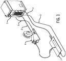
- a welding-type system 100 includes a power supply 1, and a wire feeder 6, which cooperate to provide power over a pair of weld cables 2 and 4 to a workpiece 7.
- Feeder cable 3 and a voltage sense cable 5 are used for control/feedback.
- the system shown is an Axcess® welding system, but the invention may readily be implemented with other welding-type systems.
- Welding system 100 performs generally as prior art welding systems, but includes an embedded database.
- the database stores and allows access to one or more of the process being used (MIG, pulse, Accupulse®, etc.), the voltages, currents, and wire feed speeds used for the process, the sequences of the weld (Arc Start, Start Power, Weld, Crater, etc.), special trigger functions such as dual schedule, trigger dual schedule, trigger program select, 4T operation, and trigger hold, and durations of each, as well as other variables known in such welding operations.
- Data that is stored in the database may include commanded or fedback welding data such as welding current, voltage, welding time, ramp rates, wire feed speed, etc, as well as errors, faults, alerts, etc.
- a diagram shows a welding-type system 200 includes an input circuit 202, a power circuit 204, and an output 206, as well as a controller 208.
- Circuits 202, 204 and 206, and controller 208 are, according to the present invention, part of welding power supply 1 ( Figure 1 ) in the preferred embodiment.
- Circuits 202, 204 and 206, and controller 208 are functional blocks and need not be physically distinct circuits.
- Circuits 202, 204 and 206 can be consistent with those shown in USP 6329636 , entitled Method And Apparatus For Receiving A Universal Input Voltage In A Welding, Plasma Or Heating Power Source, issued December 11, 2001. Accordingly, circuits 202, 204 and 206 may include circuitry to rectify, boost, power factor correct, invert and transform different input powers into welding-type power.
- Controller 208 includes much of the control circuitry of the prior art, including that used to turn switches on and off circuits 202, 204 and 206.
- This switch control circuitry can be implemented with other control circuitry, including digital, analog, and include micro processors, DSPs, analog circuitry, etc.
- controller 208 preferably includes circuitry to monitor and/or log operating date.
- a database module 210 includes a DBMS, and is preferably embedded into welding-type system 200.
- the database is embedded, and located inside of the controller 208, in the weld cell, or on a network connected to the weld cell.
- module 210 stores the variable listed above (and can store only some of them, or additional variables in other embodiments). When controller 208 needs to access the variable, it does so using module 210. Also, module 210 allows the user, designer or engineer to change the variables if needed using a user input 212, locally or remotely, as described below.
- welding-type system 100 includes network communication, such as WAN, LAN, over power lines, over a smart grid, and that the data transmitted and/or stored, such as on a USB drive, include arc parameters and primary information, such as harmonics data, utilization data, etc.
- the information can be stored in the database, and it or other information in or not in the database can be shared over the network or using a drive with end users, power companies, manufacturers that use welders, manufactures that supply welders, etc.
- various alternatives and arrangements are shown in the attached appendix.
Landscapes
- Engineering & Computer Science (AREA)
- Physics & Mathematics (AREA)
- Plasma & Fusion (AREA)
- Mechanical Engineering (AREA)
- Arc Welding Control (AREA)
Description
- The present invention relates generally to the art of welding-type power supplies. More specifically, it relates to a welding-type power supply, a method of controlling a welding-type system and a method of monitoring a welding-type system according to the preamble of
claims 1, 8 and 13 (see, for example,US2005/0252898 A1 ). - There are many known welding-type systems used to provide a welding-type output or welding-type power for many known applications. Welding-type system, as used herein, includes any device capable of supplying welding, plasma cutting, and/or induction heating power including converters, inverters, choppers, resonant power supplies, quasi-resonant power supplies, etc., as well as control circuitry and other ancillary circuitry associated therewith. Welding-type output, as used herein, includes outputs suitable for welding, plasma or heating. Welding type power, as used herein, refers to welding, plasma or heating power.
- Examples of prior art welding-type systems include those described in Method of Designing and Manufacturing Welding-Type Power Supplies, Albrecht, filed September 19, 2001, application number
09/956,401 March 30, 2004 as US Patent 6713721 ; Pendant Control for a Welding-Type System, L. Thomas Hayes, filed September 19, 2001, application number09/956,502 US Patent 6639182 ; Welding-Type Power Supply With A State-Based Controller, Holverson et al, filed September 19, 2001, application number09/956,548 June 8, 2004 as US Patent 6747247 ; Welding-Type System With Network And Multiple Level Messaging Between Components, Davidson et al., filed September 19, 2001, application number09/957,707 December 30, 2003 as US Patent 6670579 ; Welding-Type Power Supply With Boot Loader, L. Thomas Hayes, filed September 19, 2001, application number09/956,405 January 7, 2003 as US Patent 6,504,131 ; and Welding-Type System With Robot Calibration, Rappl et al., filed September 19, 2001, application number09/956,501 November 4, 2003 as US Patent 6642482 . - Some such systems, particularly, microprocessor controlled welding-type system store numerous variables that are used to perform the weld. For example, wether Preflow is needed for a weld and if so, how long is the preflow period. Examples of other stored variables includes the process (MIG, pulse, Accupulse®, etc.), the voltages, currents, and wire feed speeds used for the process, the sequences of the weld (Arc Start, Start Power, Weld, Crater, etc.), special trigger functions such as dual schedule, trigger dual schedule, trigger program select, 4T operation, and trigger hold, and durations of each. There are also many variables saved relating to productivity records (inches of wire used, number of arc starts, amount of time spent welding, etc). These and other variables are stored and used to control the weld and sequencer, and to keep track of welder productivity.
- In some prior art systems only the weld controller and simple user interface accessed these variables, and it was sufficient that they be stored in memory as unrelated information, with no organization or structure. However as these variables are accessed by other entities, such as over a network, other users, data loggers, productivity analyzers, etc, simply storing the variables in memory becomes problematic. Accordingly, a welding-type system that includes an effective way to store multiple variables, and to allow access to those variable from multiple sources, is desirable.
-
US 2005/0252898 A1 discloses a method for operating a welding device, in addition to a welding device comprising an energy source, especially a current source, which is controlled or regulated by means of a control device, at least one welding torch or an electrode, at least one device for detecting operating states, such as the welding temperature, and at least one calculating unit which is connected to the at least one detection device and is used to process the operating states. At least one device is used to store instructions according to which the operating states are processed and states with which the processed operating states are compared. The welding device also comprises at least one device which is connected to the calculating unit and is used to transmit messages to external receivers in such a way that associated messages can be automatically transmitted to the external receivers according to the results of said comparison. -
US 2006/0124621 A1 discloses a method and apparatus for providing welding-type power that includes a source of welding-type power and a controller. The controller is a state-based controller, and/or a deterministic control module, connected to the controller output. The state-based control module includes software instructions and a digital processor, and/or a state transition table stored in a spreadsheet data base. The controller is responsive to a feedback circuit. One or more welding peripherals, such as a wire feeder or robot, are connected to the controller. The current state may be represented by data in a first line of a spreadsheet and a state-ending event by a second, perpendicular, line of a spreadsheet. The subsequent state is determined by the intersection of the first and second lines. -
US 006133545 A discloses that a measured welding event is reproduced by a welding robot. Welding events are organized into a database by a three-dimensional measuring device and a data logging device, and the welding events are subjected to statistical and analytical processes, thereby producing operation data of a robot. -
US 2009/0173726 A1 discloses a welding system including an arc monitoring, training, and control system. The welding system includes a power supply, controller, and associated memory. When a weld is performed, the weld command and weld feedback parameters can be stored in the memory, along with associated alarm limit values. During subsequent welds, the input weld commands and actual feedback values can be compared to the established limits, and a fault signal provided to an operator or supervisor when the value exceeds the established limits. The fault signals can be used for training operators, as well as providing monitoring signals, and can be stored with weld data in a database for later analysis. In addition, collected weld data can be used to determine when to clean, repair, or replace consumables, including, for example, contact tips, wire drive liners, and drive rolls, and to monitor usage of wire and gas. -
US 6040550 A discloses a laser welding machine that includes an arbor for rotating a plurality of bellows diaphragms positioned together in side-by-side relation adjacent the laser. An optical tracker is provided for optically tracking a position of a rotating outer joint of the diaphragms as the arbor rotates. In addition, a low inertia beam steering mechanism is used for directing the laser beam to form a weld in the rotating outer joint responsive to the optical tracker. The laser may be an Nd:YAG, a diode laser, or carbon dioxide laser, for example. The optical tracker preferably includes a solid state camera and an illumination source positioned on opposite sides of the rotating outer joint to capture a shadow image of the joint. The welding machine may further include a processor and associated display operatively connected to the camera and to the beam steering means. The display may be used for displaying the shadow image of the rotating outer joint. The laser beam may be aligned horizontally, and indexing of joints and distance positioning for focusing the laser beam provided by an X-Y table. -
US 6078021 A discloses a laser welding apparatus is for laser welding an inner joint between first and second bellows diaphragms. The apparatus preferably includes a first clamp having an opening therein and having portions adjacent the opening defining a first clamping surface; and a second clamp having portions defining a second clamping surface, and wherein the first and second clamps are relatively movable to clamp the first and second metal bellows diaphragms together between the first and second clamping surfaces so that the openings in the bellows diaphragms are generally aligned with the opening in the first clamp. The apparatus also preferably includes a laser for generating a laser beam, and a beam directing element positioned in the opening of the first clamp and the openings of the first and second bellows diaphragms for directing the laser beam to weld the inner joint between the first and second bellows diaphragms. The opening of the first clamp and the recess of the second clamp are preferably sized to expose a predetermined radially inwardly extending portion of the first and second bellows diaphragms to facilitate welding with the laser beam. In addition, the apparatus also preferably includes a rotating drive arrangement for relatively rotating the first and second clamps, and the laser beam directing means to weld the inner joint. A non-metallic spacer may be positioned between the bellows diaphragms. -
US 5963450 A discloses an operator interface unit for monitoring and controlling controllers coupled to a communications network has a common database that is accessible across the network, regardless of each controllers data structure. The operator interface unit provides an apparatus for displaying, storing, and editing data obtained from the network. Data from each controller can be accessed by the unit based upon the individual controller's data structure and type through embedded objects resident in the interface unit's operating system and program. The data can then be displayed, edited, and stored by any data entry device that is capable of executing the operator interface unit's program. - According to a first aspect of the invention there is provided a welding-type system as set out in
claim 1. - According to a second aspect of the invention there is provided a method of controlling a welding-type system as set out in claim 8.
- According to a third aspect of the invention there is provided a method of monitoring a welding-type system as set out in claim 13.
- Other principal features and advantages of the invention will become apparent to those skilled in the art upon review of the following drawings, the detailed description and the appended claims.
-
-
Figure 1 is a welding-type system in accordance with the preferred embodiment of the present invention; and -
Figure 2 is block diagram in accordance with the preferred embodiment of the present invention. - Before explaining at least one embodiment of the invention in detail it is to be understood that the invention is not limited in its application to the details of construction and the arrangement of the components set forth in the following description or illustrated in the drawings. The invention is capable of other embodiments or of being practiced or carried out in various ways. Also, it is to be understood that the phraseology and terminology employed herein is for the purpose of description and should not be regarded as limiting. Like reference numerals are used to indicate like components.
- While the present invention will be illustrated with reference to a particular welding-type system it should be understood at the outset that the DBMS can be used with other welding-type systems.
- The preferred embodiment provides for implementing the invention with the Miller Axcess® or Miller Axcess E® welding power supply. The welding-type system includes a control module with an embedded database. Module, as used herein, includes software and/or hardware that cooperates to perform one or more tasks, and can include digital commands, control circuitry, power circuitry, networking hardware, etc.
- A database is a structured collection of records or data that is stored in a digital system. A database preferably is able to store large amounts of records and be accessed easily. In addition, new information and changes should also be fairly easy to input. An efficient database system often incorporates a program that manages the queries and information stored on the system. This is referred to as DBMS or a database management system.
- DBMSs are designed to provide the ability to store, manage and retrieve information through the use of tables. Tables are made up of columns and rows. Each column contains a different attribute, whereas each row represents a single record. This allows data to be organized and stored in meaningful ways.
- An embedded database system is, according to the present invention, a database management system (DBMS) which is tightly integrated with an application software that requires access. The embedded database is preferably either available commercially, or compatible therewith, to make it easier for the programmer, designer, and/or user to learn and use the database. The welding-type system can include an OS, particularly an off the shelf operating system. Alternatives include using a custom DBMS, and using a DBMS that is not embedded, and/or resides outside the weld controller, such as on a PC in the weld cell or networked to the weld cell. The DMBS is still considered part of the welding system controller, as controller is used herein, when the DMBS is located on a PC or remotely on a network.
- As explained above, some microprocessor controlled weld controller have numerous stored variables used to perform the weld. Having an embedded database to organize these variables into tables allows users to access them in a more structured manner. Also, the program that manages the database queries allows access by multiple users and helps insure that either all of the tasks of a transaction (such as a weld cycle) are performed or none of them are.
- Using a DBMS and/or an embedded database helps insure that other operations by another user cannot access or see the data in an intermediate state during a transaction. (Intermediate state refers to data that is in the process of being modified). This can be more important as additional users access these variables, and the probability that two users will be trying to change the same variable at the same time increases. Database programs are designed to handle multiple users and guarantee that transactions will be handled completely and independently from the previous/next transaction
- The DBMS, because of it's flexibility, allows each user to execute specific queries returning only the specific data that the user needs as defined by the query. While a table may contain many columns, if the user does not need all of them they will not be bothered with the extra data. DBMSs are also designed to handle large amounts of data.
- Moreover, when an application exits or fails, all information remains stored in the database. Since the database is a file within the OS if there is a hardware failure the data within the database can usually be recovered.
- Some weld cells require the use of a pc (personal computer). If there is a pc within the cell the DBMS could reside on the pc instead of being embedded. Also, if the weld cell is networked, the DBMS could reside on the network.
- Referring to
Figure 1 , a welding-type system 100 includes apower supply 1, and awire feeder 6, which cooperate to provide power over a pair ofweld cables 2 and 4 to aworkpiece 7.Feeder cable 3 and avoltage sense cable 5 are used for control/feedback. The system shown is an Axcess® welding system, but the invention may readily be implemented with other welding-type systems. - Welding system 100 performs generally as prior art welding systems, but includes an embedded database. Preferably, the database stores and allows access to one or more of the process being used (MIG, pulse, Accupulse®, etc.), the voltages, currents, and wire feed speeds used for the process, the sequences of the weld (Arc Start, Start Power, Weld, Crater, etc.), special trigger functions such as dual schedule, trigger dual schedule, trigger program select, 4T operation, and trigger hold, and durations of each, as well as other variables known in such welding operations. Data that is stored in the database may include commanded or fedback welding data such as welding current, voltage, welding time, ramp rates, wire feed speed, etc, as well as errors, faults, alerts, etc.
- Referring now to
Figure 2 , a diagram shows a welding-type system 200 includes aninput circuit 202, apower circuit 204, and anoutput 206, as well as acontroller 208.Circuits controller 208, are, according to the present invention, part of welding power supply 1 (Figure 1 ) in the preferred embodiment.Circuits controller 208 are functional blocks and need not be physically distinct circuits. -
Circuits 6329636 , entitled Method And Apparatus For Receiving A Universal Input Voltage In A Welding, Plasma Or Heating Power Source, issued December 11, 2001. Accordingly,circuits -
Controller 208 includes much of the control circuitry of the prior art, including that used to turn switches on and offcircuits controller 208 preferably includes circuitry to monitor and/or log operating date. - In accordance with the invention a
database module 210 includes a DBMS, and is preferably embedded into welding-type system 200. According to the present invention, the database is embedded, and located inside of thecontroller 208, in the weld cell, or on a network connected to the weld cell. - In
operation module 210 stores the variable listed above (and can store only some of them, or additional variables in other embodiments). Whencontroller 208 needs to access the variable, it does so usingmodule 210. Also,module 210 allows the user, designer or engineer to change the variables if needed using auser input 212, locally or remotely, as described below. - Various alternatives provide that welding-type system 100 includes network communication, such as WAN, LAN, over power lines, over a smart grid, and that the data transmitted and/or stored, such as on a USB drive, include arc parameters and primary information, such as harmonics data, utilization data, etc. The information can be stored in the database, and it or other information in or not in the database can be shared over the network or using a drive with end users, power companies, manufacturers that use welders, manufactures that supply welders, etc. Additionally, various alternatives and arrangements are shown in the attached appendix.
- Numerous modifications may be made to the present invention which still fall within the intended scope hereof. Thus, it should be apparent that there has been provided in accordance with the present invention a welding-type system, a method of controlling a welding-type system and a method of monitoring a welding-type system, an embedded database, preferably with a DBMS that fully satisfies the objectives and advantages set forth above. Although the invention has been described in conjunction with specific embodiments thereof, it is evident that many alternatives, modifications and variations will be apparent to those skilled in the art. Accordingly, it is intended to embrace all such alternatives, modifications and variations that fall within the scope of the appended claims.
Claims (14)
- A welding-type system (200) including a source of power (1), and a weld controller (208), characterised in that the controller (208) is part of the source of power (1), and further characterised in that the weld controller (208) includes an embedded database (210) comprising a database management system which is tightly integrated with the weld controller (208) that requires access to the database (210) to control the welding process, and the embedded database (210) is located inside the weld controller (208).
- The system of claim 1, wherein the database (210) includes as data stored variables used to perform the weld; and/or
the data is located in a file networked to a welding-type system (200); and/or
the embedded database (210) includes data relating to one or more one welding processes, one or more of commanded welding voltages, welding current, wire feed speed, and one or more welding sequences. - The welding-type system (200) of claim 2, wherein the database (210) includes data organized in a plurality of columns and rows.
- The welding-type system (200) of claim 3, wherein the database (210) is arranged to provide for queries from multiple users, and, optionally, the data cannot be accessed in an intermediate state.
- The welding-type system (200) of claim 4, wherein the database (210) includes data located in a file in an operating system.
- The welding-type system (200) of claim 4, wherein the database (210) includes data related to one or more fedback welding parameters of current, voltage, welding time, ramp rates and wire feed speed.
- The welding-type system (200) of claim 5, including a user input (212) connected to the database (210), wherein the user can change the data, and, optionally, the user input is further connected to a network.
- A method of controlling a welding-type system (200), characterised by:storing data in an embedded database (210), wherein the embedded database (210) includes a database management system which is tightly integrated with a weld controller (208) that requires access to the database (210) to control the welding process, and the embedded database (210) is located inside the weld controller (208);accessing the stored data using the welding controller (208), the welding controller (208) being part of a welding-type power source (1); andcontrolling the output of the welding-type power source (1) in response to the data accessed.
- The method of claim 8, wherein storing includes storing data in a file in an operating system (200); and/or
storing includes storing data in a file located on a personal computer; and/or
storing includes storing data in a file located on network connected to the welding type system; and/or
accessing includes accessing data in a file located on network connected to the welding type system; and/or
storing data includes storing data relating to more than one welding parameter; and
accessing includes accessing data for at least a selected one welding parameter. - The method of claim 8, wherein:storing data includes storing data relating to more than one welding process;accessing includes accessing data for a selected one welding process; andcontrolling includes controlling the output to be the selected welding process.
- The method of claim 8, wherein:storing data includes storing data relating to more than one welding sequence;accessing includes accessing data for at least one selected welding sequences; andcontrolling includes controlling the output to provide the at least one selected welding sequence.
- The method of claim 8, including receiving a user input and changing the data in response to the user input; and/or
including receiving a user input over network and changing the data in response to the user input. - A method of monitoring a welding-type system (200), characterised by monitoring data and storing the data in an embedded database (210), wherein the embedded database (210) includes a database management system which is tightly integrated with a weld controller (208) that requires access to the database (210) to control the welding process, the embedded database (210) is located inside the weld controller (208) and the weld controller (208) is part of a source of power (1).
- The method of claim 13, wherein monitoring data includes monitoring at least one of commanded or fed back data.
Applications Claiming Priority (3)
| Application Number | Priority Date | Filing Date | Title |
|---|---|---|---|
| US30372910P | 2010-02-12 | 2010-02-12 | |
| US12/965,171 US20110202168A1 (en) | 2010-02-12 | 2010-12-10 | Welding-Type System With Embedded Database |
| PCT/US2011/024443 WO2011100496A1 (en) | 2010-02-12 | 2011-02-11 | System for welding with an embedded database; methods of controlling such welding system, of montoring such welding; embedded database |
Publications (2)
| Publication Number | Publication Date |
|---|---|
| EP2533933A1 EP2533933A1 (en) | 2012-12-19 |
| EP2533933B1 true EP2533933B1 (en) | 2017-05-31 |
Family
ID=43901632
Family Applications (1)
| Application Number | Title | Priority Date | Filing Date |
|---|---|---|---|
| EP11705123.5A Revoked EP2533933B1 (en) | 2010-02-12 | 2011-02-11 | System for welding with an embedded database ; methods of controlling such welding system, of monitoring such welding |
Country Status (5)
| Country | Link |
|---|---|
| US (1) | US20110202168A1 (en) |
| EP (1) | EP2533933B1 (en) |
| CA (1) | CA2788538A1 (en) |
| MX (1) | MX2012009191A (en) |
| WO (1) | WO2011100496A1 (en) |
Citations (13)
| Publication number | Priority date | Publication date | Assignee | Title |
|---|---|---|---|---|
| US5963450A (en) * | 1996-12-20 | 1999-10-05 | Square D Company | Operator interface unit for monitoring and controlling devices having dissimilar data structures |
| US6040550A (en) * | 1996-10-28 | 2000-03-21 | Chang; Dale U. | Apparatus and method for laser welding the outer joints of metal bellows |
| US6078021A (en) * | 1997-08-29 | 2000-06-20 | Chang; Dale U. | Apparatus and method of laser welding inside bellows joints and spacer for manufacturing bellows |
| US6133545A (en) | 1998-05-27 | 2000-10-17 | Matsushita Electric Industrial Co., Ltd. | Welding robot |
| US20040045946A1 (en) | 2002-09-05 | 2004-03-11 | Davidson Robert R. | Autothread control for a wire feeder of a welding system |
| US20050252898A1 (en) | 2002-07-04 | 2005-11-17 | Kurt Blechinger | Method for operating a welding device, and one such welding device |
| US20060031246A1 (en) | 2004-08-04 | 2006-02-09 | Grayson Loren P | Universal database method and system |
| US20060124621A1 (en) | 2001-09-19 | 2006-06-15 | Illinois Tool Works Inc. | Welding-type power supply with a state-based controller |
| US20070056942A1 (en) | 2005-09-15 | 2007-03-15 | Lincoln Global, Inc. | Welding system sequence control apparatus |
| WO2009085373A1 (en) | 2007-12-19 | 2009-07-09 | Illinois Tool Works Inc. | Plasma cutter having thermal model for component protection |
| US20090173726A1 (en) | 2008-01-09 | 2009-07-09 | Robert Raimund Davidson | Automatic Weld Arc Monitoring System |
| US20090298024A1 (en) | 2008-05-28 | 2009-12-03 | Todd Batzler | Welding training system |
| US20090313549A1 (en) | 2008-06-16 | 2009-12-17 | Bruce Alan Casner | Configurable welding interface for automated welding applications |
Family Cites Families (9)
| Publication number | Priority date | Publication date | Assignee | Title |
|---|---|---|---|---|
| US6329636B1 (en) * | 2000-03-31 | 2001-12-11 | Illinois Tool Works Inc. | Method and apparatus for receiving a universal input voltage in a welding plasma or heating power source |
| US6795778B2 (en) * | 2001-05-24 | 2004-09-21 | Lincoln Global, Inc. | System and method for facilitating welding system diagnostics |
| US8224881B1 (en) * | 2001-06-18 | 2012-07-17 | Lincoln Global, Inc. | System and method for managing welding information |
| US6642482B2 (en) * | 2001-09-19 | 2003-11-04 | Illinois Tool Works Inc. | Welding-type system with robot calibration |
| US6713721B2 (en) * | 2001-09-19 | 2004-03-30 | Illinois Tool Works Inc. | Method of designing and manufacturing welding-type power supplies |
| US6504131B1 (en) * | 2001-09-19 | 2003-01-07 | Illinois Tool Works Inc. | Welding-type power supply with boot loader |
| US6670579B2 (en) * | 2001-09-19 | 2003-12-30 | Illinois Tool Works Inc. | Welding-type system with network and multiple level messaging between components |
| US6639182B2 (en) * | 2001-09-19 | 2003-10-28 | Illinois Tool Works Inc. | Pendant control for a welding-type system |
| US7873495B2 (en) * | 2009-02-24 | 2011-01-18 | Inspectech Corporation | Welding quality control and monitoring system |
-
2010
- 2010-12-10 US US12/965,171 patent/US20110202168A1/en not_active Abandoned
-
2011
- 2011-02-11 MX MX2012009191A patent/MX2012009191A/en active IP Right Grant
- 2011-02-11 EP EP11705123.5A patent/EP2533933B1/en not_active Revoked
- 2011-02-11 CA CA2788538A patent/CA2788538A1/en not_active Abandoned
- 2011-02-11 WO PCT/US2011/024443 patent/WO2011100496A1/en not_active Ceased
Patent Citations (13)
| Publication number | Priority date | Publication date | Assignee | Title |
|---|---|---|---|---|
| US6040550A (en) * | 1996-10-28 | 2000-03-21 | Chang; Dale U. | Apparatus and method for laser welding the outer joints of metal bellows |
| US5963450A (en) * | 1996-12-20 | 1999-10-05 | Square D Company | Operator interface unit for monitoring and controlling devices having dissimilar data structures |
| US6078021A (en) * | 1997-08-29 | 2000-06-20 | Chang; Dale U. | Apparatus and method of laser welding inside bellows joints and spacer for manufacturing bellows |
| US6133545A (en) | 1998-05-27 | 2000-10-17 | Matsushita Electric Industrial Co., Ltd. | Welding robot |
| US20060124621A1 (en) | 2001-09-19 | 2006-06-15 | Illinois Tool Works Inc. | Welding-type power supply with a state-based controller |
| US20050252898A1 (en) | 2002-07-04 | 2005-11-17 | Kurt Blechinger | Method for operating a welding device, and one such welding device |
| US20040045946A1 (en) | 2002-09-05 | 2004-03-11 | Davidson Robert R. | Autothread control for a wire feeder of a welding system |
| US20060031246A1 (en) | 2004-08-04 | 2006-02-09 | Grayson Loren P | Universal database method and system |
| US20070056942A1 (en) | 2005-09-15 | 2007-03-15 | Lincoln Global, Inc. | Welding system sequence control apparatus |
| WO2009085373A1 (en) | 2007-12-19 | 2009-07-09 | Illinois Tool Works Inc. | Plasma cutter having thermal model for component protection |
| US20090173726A1 (en) | 2008-01-09 | 2009-07-09 | Robert Raimund Davidson | Automatic Weld Arc Monitoring System |
| US20090298024A1 (en) | 2008-05-28 | 2009-12-03 | Todd Batzler | Welding training system |
| US20090313549A1 (en) | 2008-06-16 | 2009-12-17 | Bruce Alan Casner | Configurable welding interface for automated welding applications |
Non-Patent Citations (2)
| Title |
|---|
| EUGENE K. BUECHELE: "Designing data-centric software", 9 November 2005 (2005-11-09), XP055472775, Retrieved from the Internet <URL:https://www.embedded.com/design/prototyping-and-development/4006484/Designing-data-centric-software> |
| MILLER ELECTRIC MFG.: "Auto-Axcess 450 DI", OWNER`S MANUAL, October 2008 (2008-10-01), XP055472784, Retrieved from the Internet <URL:https://www.millerwelds.com/files/owners-manuals/o228873g_mil.pdf> [retrieved on 20180221] |
Also Published As
| Publication number | Publication date |
|---|---|
| EP2533933A1 (en) | 2012-12-19 |
| US20110202168A1 (en) | 2011-08-18 |
| WO2011100496A1 (en) | 2011-08-18 |
| CA2788538A1 (en) | 2011-08-18 |
| MX2012009191A (en) | 2012-08-23 |
Similar Documents
| Publication | Publication Date | Title |
|---|---|---|
| CA2625289C (en) | System and method for managing welding procedures and welding resources | |
| EP1683599B1 (en) | Integrating sensors over a digital link | |
| JP7552964B2 (en) | SYSTEM AND METHOD FOR PROVIDING PATTERN RECOGNITION AND DATA ANALYSIS IN WELDING AND CUTTING - Patent application | |
| US10391575B2 (en) | Weld bank data structures for welding applications | |
| US20030192865A1 (en) | Method and apparatus for laser piercing and cutting metal sheet and plate | |
| CN110605489A (en) | Precise control system and welding method for welding parameters of complex structure | |
| KR102257260B1 (en) | Welding system data management system and method | |
| US12602034B2 (en) | Distributed weld monitoring system with job tracking | |
| CN113020813B (en) | Design cutting and welding integrated production system and production method thereof | |
| EP2533933B1 (en) | System for welding with an embedded database ; methods of controlling such welding system, of monitoring such welding | |
| US20240335897A1 (en) | Weld monitoring systems with unknown downtime disabling | |
| CN113798673A (en) | A laser wire filler welding quality traceability device, method, workstation and production line | |
| CN114654090A (en) | Laser welding tracing method, system, device, workstation and production line | |
| JP7281789B2 (en) | Identifier management method, robot control device and general control device | |
| CN223406158U (en) | A host computer system for digital automatic welding platform | |
| EP4725660A1 (en) | Systems and methods for optimizing material processing operations | |
| US20220229417A1 (en) | Identifier management method, robot control device, and integrated control device | |
| AU2016253678A1 (en) | A cnc machine programming and program management method | |
| Ferguson Jr et al. | Adaptive welding for shipyards | |
| CN114633040A (en) | Workpiece welding control method, device and system and storage medium |
Legal Events
| Date | Code | Title | Description |
|---|---|---|---|
| PUAI | Public reference made under article 153(3) epc to a published international application that has entered the european phase |
Free format text: ORIGINAL CODE: 0009012 |
|
| 17P | Request for examination filed |
Effective date: 20120809 |
|
| AK | Designated contracting states |
Kind code of ref document: A1 Designated state(s): AL AT BE BG CH CY CZ DE DK EE ES FI FR GB GR HR HU IE IS IT LI LT LU LV MC MK MT NL NO PL PT RO RS SE SI SK SM TR |
|
| DAX | Request for extension of the european patent (deleted) | ||
| 17Q | First examination report despatched |
Effective date: 20131119 |
|
| RAP1 | Party data changed (applicant data changed or rights of an application transferred) |
Owner name: ILLINOIS TOOL WORKS INC. |
|
| GRAP | Despatch of communication of intention to grant a patent |
Free format text: ORIGINAL CODE: EPIDOSNIGR1 |
|
| STAA | Information on the status of an ep patent application or granted ep patent |
Free format text: STATUS: GRANT OF PATENT IS INTENDED |
|
| INTG | Intention to grant announced |
Effective date: 20161221 |
|
| GRAS | Grant fee paid |
Free format text: ORIGINAL CODE: EPIDOSNIGR3 |
|
| GRAA | (expected) grant |
Free format text: ORIGINAL CODE: 0009210 |
|
| STAA | Information on the status of an ep patent application or granted ep patent |
Free format text: STATUS: THE PATENT HAS BEEN GRANTED |
|
| AK | Designated contracting states |
Kind code of ref document: B1 Designated state(s): AL AT BE BG CH CY CZ DE DK EE ES FI FR GB GR HR HU IE IS IT LI LT LU LV MC MK MT NL NO PL PT RO RS SE SI SK SM TR |
|
| REG | Reference to a national code |
Ref country code: CH Ref legal event code: EP Ref country code: GB Ref legal event code: FG4D |
|
| REG | Reference to a national code |
Ref country code: AT Ref legal event code: REF Ref document number: 896993 Country of ref document: AT Kind code of ref document: T Effective date: 20170615 |
|
| REG | Reference to a national code |
Ref country code: IE Ref legal event code: FG4D |
|
| REG | Reference to a national code |
Ref country code: DE Ref legal event code: R096 Ref document number: 602011038310 Country of ref document: DE |
|
| REG | Reference to a national code |
Ref country code: NL Ref legal event code: MP Effective date: 20170531 |
|
| REG | Reference to a national code |
Ref country code: LT Ref legal event code: MG4D |
|
| REG | Reference to a national code |
Ref country code: AT Ref legal event code: MK05 Ref document number: 896993 Country of ref document: AT Kind code of ref document: T Effective date: 20170531 |
|
| PG25 | Lapsed in a contracting state [announced via postgrant information from national office to epo] |
Ref country code: AT Free format text: LAPSE BECAUSE OF FAILURE TO SUBMIT A TRANSLATION OF THE DESCRIPTION OR TO PAY THE FEE WITHIN THE PRESCRIBED TIME-LIMIT Effective date: 20170531 Ref country code: HR Free format text: LAPSE BECAUSE OF FAILURE TO SUBMIT A TRANSLATION OF THE DESCRIPTION OR TO PAY THE FEE WITHIN THE PRESCRIBED TIME-LIMIT Effective date: 20170531 Ref country code: NO Free format text: LAPSE BECAUSE OF FAILURE TO SUBMIT A TRANSLATION OF THE DESCRIPTION OR TO PAY THE FEE WITHIN THE PRESCRIBED TIME-LIMIT Effective date: 20170831 Ref country code: FI Free format text: LAPSE BECAUSE OF FAILURE TO SUBMIT A TRANSLATION OF THE DESCRIPTION OR TO PAY THE FEE WITHIN THE PRESCRIBED TIME-LIMIT Effective date: 20170531 Ref country code: LT Free format text: LAPSE BECAUSE OF FAILURE TO SUBMIT A TRANSLATION OF THE DESCRIPTION OR TO PAY THE FEE WITHIN THE PRESCRIBED TIME-LIMIT Effective date: 20170531 Ref country code: GR Free format text: LAPSE BECAUSE OF FAILURE TO SUBMIT A TRANSLATION OF THE DESCRIPTION OR TO PAY THE FEE WITHIN THE PRESCRIBED TIME-LIMIT Effective date: 20170901 Ref country code: ES Free format text: LAPSE BECAUSE OF FAILURE TO SUBMIT A TRANSLATION OF THE DESCRIPTION OR TO PAY THE FEE WITHIN THE PRESCRIBED TIME-LIMIT Effective date: 20170531 |
|
| PG25 | Lapsed in a contracting state [announced via postgrant information from national office to epo] |
Ref country code: NL Free format text: LAPSE BECAUSE OF FAILURE TO SUBMIT A TRANSLATION OF THE DESCRIPTION OR TO PAY THE FEE WITHIN THE PRESCRIBED TIME-LIMIT Effective date: 20170531 Ref country code: SE Free format text: LAPSE BECAUSE OF FAILURE TO SUBMIT A TRANSLATION OF THE DESCRIPTION OR TO PAY THE FEE WITHIN THE PRESCRIBED TIME-LIMIT Effective date: 20170531 Ref country code: BG Free format text: LAPSE BECAUSE OF FAILURE TO SUBMIT A TRANSLATION OF THE DESCRIPTION OR TO PAY THE FEE WITHIN THE PRESCRIBED TIME-LIMIT Effective date: 20170831 Ref country code: IS Free format text: LAPSE BECAUSE OF FAILURE TO SUBMIT A TRANSLATION OF THE DESCRIPTION OR TO PAY THE FEE WITHIN THE PRESCRIBED TIME-LIMIT Effective date: 20170930 Ref country code: RS Free format text: LAPSE BECAUSE OF FAILURE TO SUBMIT A TRANSLATION OF THE DESCRIPTION OR TO PAY THE FEE WITHIN THE PRESCRIBED TIME-LIMIT Effective date: 20170531 Ref country code: LV Free format text: LAPSE BECAUSE OF FAILURE TO SUBMIT A TRANSLATION OF THE DESCRIPTION OR TO PAY THE FEE WITHIN THE PRESCRIBED TIME-LIMIT Effective date: 20170531 |
|
| PG25 | Lapsed in a contracting state [announced via postgrant information from national office to epo] |
Ref country code: CZ Free format text: LAPSE BECAUSE OF FAILURE TO SUBMIT A TRANSLATION OF THE DESCRIPTION OR TO PAY THE FEE WITHIN THE PRESCRIBED TIME-LIMIT Effective date: 20170531 Ref country code: RO Free format text: LAPSE BECAUSE OF FAILURE TO SUBMIT A TRANSLATION OF THE DESCRIPTION OR TO PAY THE FEE WITHIN THE PRESCRIBED TIME-LIMIT Effective date: 20170531 Ref country code: SK Free format text: LAPSE BECAUSE OF FAILURE TO SUBMIT A TRANSLATION OF THE DESCRIPTION OR TO PAY THE FEE WITHIN THE PRESCRIBED TIME-LIMIT Effective date: 20170531 Ref country code: DK Free format text: LAPSE BECAUSE OF FAILURE TO SUBMIT A TRANSLATION OF THE DESCRIPTION OR TO PAY THE FEE WITHIN THE PRESCRIBED TIME-LIMIT Effective date: 20170531 Ref country code: EE Free format text: LAPSE BECAUSE OF FAILURE TO SUBMIT A TRANSLATION OF THE DESCRIPTION OR TO PAY THE FEE WITHIN THE PRESCRIBED TIME-LIMIT Effective date: 20170531 |
|
| REG | Reference to a national code |
Ref country code: FR Ref legal event code: PLFP Year of fee payment: 8 |
|
| PG25 | Lapsed in a contracting state [announced via postgrant information from national office to epo] |
Ref country code: PL Free format text: LAPSE BECAUSE OF FAILURE TO SUBMIT A TRANSLATION OF THE DESCRIPTION OR TO PAY THE FEE WITHIN THE PRESCRIBED TIME-LIMIT Effective date: 20170531 Ref country code: SM Free format text: LAPSE BECAUSE OF FAILURE TO SUBMIT A TRANSLATION OF THE DESCRIPTION OR TO PAY THE FEE WITHIN THE PRESCRIBED TIME-LIMIT Effective date: 20170531 |
|
| REG | Reference to a national code |
Ref country code: DE Ref legal event code: R026 Ref document number: 602011038310 Country of ref document: DE |
|
| PLBI | Opposition filed |
Free format text: ORIGINAL CODE: 0009260 |
|
| PLAX | Notice of opposition and request to file observation + time limit sent |
Free format text: ORIGINAL CODE: EPIDOSNOBS2 |
|
| 26 | Opposition filed |
Opponent name: FRONIUS INTERNATIONAL GMBH Effective date: 20180228 |
|
| PGFP | Annual fee paid to national office [announced via postgrant information from national office to epo] |
Ref country code: GB Payment date: 20180227 Year of fee payment: 8 |
|
| PG25 | Lapsed in a contracting state [announced via postgrant information from national office to epo] |
Ref country code: SI Free format text: LAPSE BECAUSE OF FAILURE TO SUBMIT A TRANSLATION OF THE DESCRIPTION OR TO PAY THE FEE WITHIN THE PRESCRIBED TIME-LIMIT Effective date: 20170531 |
|
| PLBB | Reply of patent proprietor to notice(s) of opposition received |
Free format text: ORIGINAL CODE: EPIDOSNOBS3 |
|
| REG | Reference to a national code |
Ref country code: CH Ref legal event code: PL |
|
| PG25 | Lapsed in a contracting state [announced via postgrant information from national office to epo] |
Ref country code: MC Free format text: LAPSE BECAUSE OF FAILURE TO SUBMIT A TRANSLATION OF THE DESCRIPTION OR TO PAY THE FEE WITHIN THE PRESCRIBED TIME-LIMIT Effective date: 20170531 |
|
| REG | Reference to a national code |
Ref country code: IE Ref legal event code: MM4A |
|
| REG | Reference to a national code |
Ref country code: BE Ref legal event code: MM Effective date: 20180228 |
|
| PG25 | Lapsed in a contracting state [announced via postgrant information from national office to epo] |
Ref country code: CH Free format text: LAPSE BECAUSE OF NON-PAYMENT OF DUE FEES Effective date: 20180228 Ref country code: LI Free format text: LAPSE BECAUSE OF NON-PAYMENT OF DUE FEES Effective date: 20180228 Ref country code: LU Free format text: LAPSE BECAUSE OF NON-PAYMENT OF DUE FEES Effective date: 20180211 |
|
| PG25 | Lapsed in a contracting state [announced via postgrant information from national office to epo] |
Ref country code: IE Free format text: LAPSE BECAUSE OF NON-PAYMENT OF DUE FEES Effective date: 20180211 |
|
| PG25 | Lapsed in a contracting state [announced via postgrant information from national office to epo] |
Ref country code: BE Free format text: LAPSE BECAUSE OF NON-PAYMENT OF DUE FEES Effective date: 20180228 |
|
| GBPC | Gb: european patent ceased through non-payment of renewal fee |
Effective date: 20190211 |
|
| REG | Reference to a national code |
Ref country code: DE Ref legal event code: R064 Ref document number: 602011038310 Country of ref document: DE Ref country code: DE Ref legal event code: R103 Ref document number: 602011038310 Country of ref document: DE |
|
| RDAF | Communication despatched that patent is revoked |
Free format text: ORIGINAL CODE: EPIDOSNREV1 |
|
| PG25 | Lapsed in a contracting state [announced via postgrant information from national office to epo] |
Ref country code: GB Free format text: LAPSE BECAUSE OF NON-PAYMENT OF DUE FEES Effective date: 20190211 Ref country code: MT Free format text: LAPSE BECAUSE OF NON-PAYMENT OF DUE FEES Effective date: 20180211 |
|
| PG25 | Lapsed in a contracting state [announced via postgrant information from national office to epo] |
Ref country code: TR Free format text: LAPSE BECAUSE OF FAILURE TO SUBMIT A TRANSLATION OF THE DESCRIPTION OR TO PAY THE FEE WITHIN THE PRESCRIBED TIME-LIMIT Effective date: 20170531 |
|
| PGFP | Annual fee paid to national office [announced via postgrant information from national office to epo] |
Ref country code: IT Payment date: 20200220 Year of fee payment: 10 Ref country code: DE Payment date: 20200227 Year of fee payment: 10 |
|
| PG25 | Lapsed in a contracting state [announced via postgrant information from national office to epo] |
Ref country code: HU Free format text: LAPSE BECAUSE OF FAILURE TO SUBMIT A TRANSLATION OF THE DESCRIPTION OR TO PAY THE FEE WITHIN THE PRESCRIBED TIME-LIMIT; INVALID AB INITIO Effective date: 20110211 Ref country code: PT Free format text: LAPSE BECAUSE OF FAILURE TO SUBMIT A TRANSLATION OF THE DESCRIPTION OR TO PAY THE FEE WITHIN THE PRESCRIBED TIME-LIMIT Effective date: 20170531 |
|
| PG25 | Lapsed in a contracting state [announced via postgrant information from national office to epo] |
Ref country code: MK Free format text: LAPSE BECAUSE OF NON-PAYMENT OF DUE FEES Effective date: 20170531 Ref country code: CY Free format text: LAPSE BECAUSE OF FAILURE TO SUBMIT A TRANSLATION OF THE DESCRIPTION OR TO PAY THE FEE WITHIN THE PRESCRIBED TIME-LIMIT Effective date: 20170531 |
|
| PGFP | Annual fee paid to national office [announced via postgrant information from national office to epo] |
Ref country code: FR Payment date: 20200225 Year of fee payment: 10 |
|
| RDAG | Patent revoked |
Free format text: ORIGINAL CODE: 0009271 |
|
| STAA | Information on the status of an ep patent application or granted ep patent |
Free format text: STATUS: PATENT REVOKED |
|
| PG25 | Lapsed in a contracting state [announced via postgrant information from national office to epo] |
Ref country code: AL Free format text: LAPSE BECAUSE OF FAILURE TO SUBMIT A TRANSLATION OF THE DESCRIPTION OR TO PAY THE FEE WITHIN THE PRESCRIBED TIME-LIMIT Effective date: 20170531 |
|
| REG | Reference to a national code |
Ref country code: FI Ref legal event code: MGE |
|
| 27W | Patent revoked |
Effective date: 20191107 |