EP2533511A1 - Delay estimator - Google Patents
Delay estimator Download PDFInfo
- Publication number
- EP2533511A1 EP2533511A1 EP12183421A EP12183421A EP2533511A1 EP 2533511 A1 EP2533511 A1 EP 2533511A1 EP 12183421 A EP12183421 A EP 12183421A EP 12183421 A EP12183421 A EP 12183421A EP 2533511 A1 EP2533511 A1 EP 2533511A1
- Authority
- EP
- European Patent Office
- Prior art keywords
- signal
- delay
- values
- point
- time
- Prior art date
- Legal status (The legal status is an assumption and is not a legal conclusion. Google has not performed a legal analysis and makes no representation as to the accuracy of the status listed.)
- Granted
Links
Images


Classifications
-
- H—ELECTRICITY
- H04—ELECTRIC COMMUNICATION TECHNIQUE
- H04M—TELEPHONIC COMMUNICATION
- H04M9/00—Arrangements for interconnection not involving centralised switching
- H04M9/08—Two-way loud-speaking telephone systems with means for conditioning the signal, e.g. for suppressing echoes for one or both directions of traffic
- H04M9/082—Two-way loud-speaking telephone systems with means for conditioning the signal, e.g. for suppressing echoes for one or both directions of traffic using echo cancellers
-
- H—ELECTRICITY
- H04—ELECTRIC COMMUNICATION TECHNIQUE
- H04B—TRANSMISSION
- H04B3/00—Line transmission systems
- H04B3/02—Details
- H04B3/46—Monitoring; Testing
Definitions
- the present invention relates generally to methods and devices for use in communications networks. More precisely, it relates to a method and a device for estimating the delay of a signal travelling between two points in a communications network.
- the invention can in particular be used in applications for estimating or mitigating echo in communication equipment.
- the delay is the time elapsed between the appearance of, say, a characteristic signal feature at the reference point and its reappearance at the reception point.
- the delay may be the sum of the propagation time in various conducting materials, processing time in decoders and encoders, particularly conversions between analogue and digital format, waiting time during routing in packet-switched networks, and possibly propagation time in air if the signal is transmitted in acoustic form in some segment of the path.
- Accurate estimates of the delay of an acoustic or electric signal travelling through a system are valuable in a number of applications, for instance, in echo cancellation and echo suppression in communications equipment, de-reverberation, echo localization, alignment of audio files for the purpose of fingerprinting, and the alignment of audio signals in recording studios.
- a far-end party and a near-end party communicate using a telecommunications network.
- the near-end party would like to receive only the speech signal spoken by the far-end speaker.
- the near-end party may additionally receive the (distorted and delayed) speech signal spoken by him- or herself.
- This signal component in the signal travelling towards the near-end party is referred to as the echo signal.
- the feedback path is acoustic and consists of acoustic speakers at the far-end and microphones that acquire the echo signal.
- the feedback path is electronic and results from imperfect transmission-line terminations.
- the echo signal must be decreased or eliminated. This is normally done by digital computing means using adaptive filtering (echo cancellation) and/or by gain control (echo suppression).
- the adaptive filter of echo cancellation is optimized to remove the signal component that correlates with the signal travelling towards the far-end party by subtracting it from the signal travelling towards the near-end party. Finding the relative delay (the bulk delay ) of the signal travelling to the far end and the echo signal is implicit in this optimization and is generally based on correlation, albeit sometimes in a broad sense. An initial estimate of the bulk delay is commonly used to reduce the required number of the correlation computations for echo cancellation.
- Echo suppression In the case of echo suppression, heuristic rules are generally used to suppress the signal travelling towards the near end whenever it mostly consists of the signal spoken by the near-end party. Echo suppression requires knowledge of the relative delay between the signal travelling to the far end and the echo signal. An estimate of the relative delay is usually computed by means of cross correlation.
- Alternative delay estimation methods can be used to reduce the search range in echo cancellation and as a first or final estimate of the delay for echo suppression.
- An object of the present invention is to wholly or partly overcome the above disadvantages and drawbacks of the prior art and to provide improved methods and devices for delay estimation. Another objective is to provide low sensitivity to nonlinear distortions in the feedback path. It is desirable to obtain estimates having relatively high accuracy at a relatively low computational effort.
- the present invention provides a method and apparatus for finding an estimate of the delay of a signal between two points separate in space.
- preferred embodiments of the invention are defined by the dependent claims.
- the present invention does not require stable statistics, its formulation is based on the concept of joint probability of values of measurements of the signal at the reference point and of the signal at the reception point, as a function of the time delay between the measurements.
- the measurements can be of any suitable quantity, such as momentary or average energy content.
- Existing methods for delay estimation generally use averages of cross-correlations or averages of differences between measurements to evaluate the delay.
- the present invention is based on counting co-occurrences of value ranges in the two sets of measurements, which forms a discrete approximation to the joint probability for data with stable statistics. It is well-known to persons skilled in the art that the joint probability provides more information about the relation between two variables than the average cross-correlation or the average difference. Thus, usage of the joint probability facilitates a better estimate of the delay.
- the measurements are quantized into a simplified, preferably binary, form by comparison with a threshold adapted to a typical magnitude of the quantity as evaluated at the reference and the reception point.
- the method may apply different thresholds at the two points for values of a given quantity.
- two binary sequences are obtained consisting of one-bit-quantized (i.e., Boolean) values of the quantity as evaluated at the reference point and the reception point.
- a binary 1 denotes strong audio activity, such as a speaker speaking
- a binary 0 denotes weak audio activity, such as silence or near silence.
- the thresholds are selected in a natural manner.
- a signal propagates between the reference point and the reception point without delay.
- the combination of strong audio activity at the reception point and weak audio activity at the reference point, corresponding to the pair (1,0) should not be possible in a pair, as the high value measured at the reference point should have given rise to a high value at the reception point too.
- the delay is D, a non-zero number, the pair (1,0) may occur in pairs of simultaneously measured values.
- the delay D can be found counting the co-occurrences (1,0) for different back shifts and selecting the delay with the lowest count (relative frequency). For better performance, the other co-occurrences can also be considered.
- this procedure can be generalized in that the relative frequencies are not determined, but a penalty is assigned to the least probable co-occurrence(s) and stored in a table.
- penalties for corresponding quantized values in the binary sequences when shifted back by one of the candidate delays are read from the table and summed.
- a candidate delay corresponding to the most probable true delay can be elected. In the exemplary case discussed above, one may accordingly assign a penalty of -1 to the co-occurrence (1,0) and a penalty of 0 to the three others.
- the quantity that is evaluated from the signal may be a momentary value or an average over a time segment of finite length.
- the length is between 50 and 1000 milliseconds. In some embodiments, two or more of such time segments may overlap.
- a quantity that is simple to evaluate and leads to a distinctive indication of the delay already with a small number of measurements may be used:
- more than one quantity can be evaluated from the signal. Since more information is thus available for a given number of time instants, an indication of the most likely candidate delay will then be obtained faster at the price of an increased momentary computational load.
- signal powers for a windowed signal segment in a plurality of frequency bands are used as quantities. It is then advantageous to pass the signal through a filter bank, before evaluating the signal power.
- the filters may be digital, preferably applying some Fourier-transform method, or may be analogue.
- the signal power of a windowed signal segment as a function of the frequency bands is referred to as a periodogram. If each component in a periodogram is then compared with a threshold a binary vector is obtained having as many components as the periodogram. This means that if 32 bands are used, each periodogram, representing a short-time power spectrum of the signal, can be stored in a single 32-bit integer, so that the storage requirements are negligible.
- the values of the quantity may be quantized in more steps than two, so that multi-bit quantized values are obtained. If, for instance, the values are compared with three different thresholds, each value can be placed in one of four intervals, the endpoints of which correspond to the thresholds. As is well-known, that interval of the four which contains the value can be characterized by a two-bit binary representation of its ordinal number.
- the number of thresholds used for reference values may be different than the number used for reception values.
- embodiments of the invention may equally well comprise a number of quantization levels that is not a power of 2. While preferably the number of thresholds is small, some application may benefit from using an increased number of thresholds at either the reference point, the reception point or both.
- a delay-estimating device as defined in appended claim 7 is provided.
- the delay-estimating device comprises at least one threshold circuit for quantizing the measured values of the at least one quantity, wherein the value of the threshold is variable and is provided by a specifying circuit.
- the threshold circuit is adapted to quantize values of the quantity or quantities (as measured at the reference point, the reception point or both) with respect to more than one threshold for each quantity.
- at least one of the reference point and the reception point is located in a communications network.
- the delay-estimating device may be adapted to measure at least one quantity which is a momentary value or at least one quantity which is a time average over a finite time interval. Such time intervals may or may not overlap in time.
- a delay-estimating device may be a component in an echo-cancelling circuit as defined by claim 15.
- the echo-cancelling circuit may for example contain a feed-forward adaptive filter, the quantitative characteristics of which are variable as a function of the delay estimated by the device according to the invention.
- Figure 1 shows the acoustic feedback loop commonly present in hands-free communication devices such as computers used for voice-over-IP speaker phones or hands-free telephones.
- the technical problem to be solved can be exemplified by the case of a telephone call involving one near-end party and one far-end party.
- the input signal 500 is the speech signal spoken by the near-end party. It arrives at the far-end in digital format, and can be in the form of a compressed bit stream.
- Decoder 211 contains a digital-to-analogue converter that converts the signal to a continuous-time analogue signal. If the signal is compressed then decoder 211 uses a decoding algorithm to decompress the signal as well.
- Analogue signal 501 is sent to one or more speakers 212, which generate an acoustic signal 502 that is subjected to the room transfer function 213.
- the modified acoustic signal 503 is acquired by the microphone 214.
- Microphone 214 may additionally have the input 504, spoken by the far-end party, and other far-end generated acoustic signals.
- the analogue signal 505 that forms the output of the microphone is sent to encoder 215 that either performs an analogue-to-digital conversion or an analogue-to-digital conversion followed by compression by means of any suitable algorithm.
- the resulting bit stream 510 is transmitted to the near-end party.
- signal 510 even when signal 504 is not active (is zero), signal 510 generally differs significantly in amplitude and spectral colouring from signal 500, and is delayed. Without appropriate compensation, the near-end party will receive a delayed and distorted copy of the speech signal spoken by him- or herself. This echo that the near-end party hears makes conversation difficult. To remove the problem, echo cancellation and/or suppression is used. The computational effort to perform echo cancellation and suppression is significantly reduced if the delay of signal 510 relative to signal 500 is known.
- the present invention is adapted to estimate the delay between the signal 500 sent from the near end and the signal 510 received at the near end, using only signals 500 and 510 as input to the estimation procedure. Echo cancellation and suppression is an important application of the current invention.
- the underlying method will be described in terms of the information that is received and processed.
- the quantity used for estimating the delay between the signals will be the signal power in different frequency bands. More precisely, the measurement of the signal 510 at the reference point and the measurement of the signal 500 at the reception point are modelled, respectively, as functions x(t), y(t) of continuous time.
- frequency bands (these could correspond to the frequency bins of a Fourier-transform filter)
- w(t) is a window, which advantageously can be chosen to be the Hann window.
- the time integral is replaced by a summation and no integration in frequency is used; q then simply indexes the frequency bins.
- the thresholds can also be the average channel values, the median channel values or any other quantile value of the channels.
- the cross correlation is a function of the time shifts, the maximum of which occurs exactly when the time-shifted signals exhibit the largest degree of likeness.
- co-occurrences (1,1) and (0,0) contribute to the value of the cross correlation
- co-occurrences (0,1) and (1,0) do not.
- This simple search for likeness is not suitable in an arbitrary situation. For instance, when the feedback path is nonlinear, cross correlation performs poorly. Moreover, even when the delay varies somewhat over time, the present method will perform well, while cross correlation methods generally will fail due to the lack of a probability distribution that is stable in time.
- K time instants are used for calculating ⁇ q,m for all candidate delays. If in some embodiment it is desirable to use an equal number of columns in the matrices, the method may perform averaging over a smaller number of time instants for the larger candidate delays, so that no extra columns to the right need to be included in X.
- a particular embodiment of the invention does not compare consecutive pairs of time instants, but compares every other pair, every third pair, etc.
- matrices X and Y then have KN+D M and KN columns. This embodiment is advantageous in virtue of its reduced computational load.
- Table 1 above shows two alternative sets of penalties in addition to that discussed in section Summary of the invention, which penalizes the least probable event (1,0) only.
- (1,0) is expected to have low probability for the correct delay it is penalized, proportionally to the number of times it occurs.
- the first alternative set of penalties is simple in so far as the penalties are integer numbers that reflect the unequal counts expected for (0,0), (0,1) and (1,1). Again, as (1,0) should not occur for the correct delay, it is penalized most strongly.
- the co-occurrences (0,0) and (1,1) are weak indicators that the delay is correct and for this reason receive a negative penalty. Co-occurrence (0,1) does not provide information about the correctness of the candidate delay and therefore is assigned a neutral penalty.
- the second alternative set of penalties in Table 1 consists of the probabilities themselves. For stable statistics, this choice results in a minimum in the average penalty if the observations have the correct probability distribution, that is, if the observations are back-shifted by the correct delay.
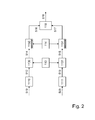
- Two signals 500 and 510 form the input. These two signals may correspond to the acoustic echo feedback path illustrated in figure 1 , or any other set of signals that form the input and the output of a physical system. More generally, they can be any two signals such that the second contains a delayed copy of the first.
- Each of the input signals 510 and 500 is separately pre-processed in pre-processors 1110 and 1111, which have identical functionalities.
- the output of each pre-processor is a sequence of vectors (or scalars).
- vector sequences 512 and 513 are sequences of periodograms for the input signals 510 and 500, respectively.
- FIG. 3 shows the operation of pre-processor 1110 in more detail.
- Pre-processor 1111 functions similarly.
- the input signal 510 is first segmented into time segments that may overlap in a segmenter 311.
- the successive segments created by segmenter 311 are separated in time by 10 ms and the segments have a length of 20 ms.
- a transformer 312 performs a windowing and Fourier-transform operation.
- the output of transformer 312 is a discrete, short-time complex spectrum.
- Periodogram computer 313 takes this complex spectrum and applies the absolute operator to each spectrum component and squares the results to render a periodogram 512, which is a short-term power spectrum estimate.
- the periodogram is a vector property of the signal segment that is the output of segmenter 311.
- the specifying circuit 112 stores what subset of channels is to be used for delay estimation. Thus, the specifying circuit 112 specifies the active channels. Specifying circuit 112 also stores the thresholds that are to be applied to the active channels. A first and second threshold circuit 1130 and 1131 determine for each active channel whether the value for the current segment is above or below the threshold. This operation is equivalent to one-bit quantization.
- Vector signals 514 and 515 are a time-sequence of bit vectors, in which each one-bit component expresses the value of an active part of the periodogram (representing a short-term power spectrum) relative to the thresholds set by specifier 112.
- each of the vectors of vector signals 514 and 515 can be stored in a single digital integer number, reducing storage requirements on most computing devices significantly.
- This approach is particularly efficient if 32 or 64 channels are active, as the combined hardware and software on many computing devices are adapted to handle 32- and 64-bit integers.
- this method of using integers to denote the one-bit quantization index facilitates generalization for multiple thresholds
- the output is then an index that requires for m thresholds log 2 (m+1) bits to be described.
- each vector has log 2 (m+1) bit planes that each can be described by an integer.
- a bit vector written in the form of a single integer one-bit quantization
- bit vectors are used without being stored as spectral integers.
- Buffer specifier 114 specifies the length of a first and second shift register 1150, 1151. For reasons already stated, the second shift register 1151 can be shorter than the first shift register 1150. Thus, the buffer specifier specifies how many spectral integers are stored in shift registers 1150 and 1151 for each active channel. Whenever a new spectral integer is acquired, the least recent spectral integer is discarded. It is the age of the latest discarded spectral integer (the length of the shift register) that is specified by buffer specifier 114. Advantageously this age is the same for all channels in signal 514 and, separately, for all channels in signal 515.
- the actual age used depends on the signal that the delay is estimated for. If the delay is constant, the accuracy of the delay estimate increases with the length of the buffer. If the delay is changing, then an age that is a good compromise for the rate of change of the delay must be selected. In this embodiment this is determined by a designer of the system, but automated procedures can also be used for this purpose. As seen above, the lengths of the buffers can be calculated on the basis of the largest candidate delay, the desired number of time instants to be compared and, when applicable, their consecutive spacing.
- a delay assessment circuit 118 which can be implemented in a number of different ways, is adapted to calculate the average penalty for each candidate delay.
- the delay assessment circuit 118 receives the entire buffer content 516, 517 from buffers 1150,1151 and makes computations according to equation (5). From the results of the computations, the assessment circuit 118 outputs a signal indicative of the estimated delay (518).
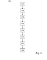
- Figure 4 illustrates an embodiment of a method 400 according to the invention for estimating the delay of a signal between a reference point and a reception point.
- Figure 4 is a flowchart depicting the steps of the method in the case of three quantities and five candidate delays.
- step 410 the three quantities are defined.
- step 412 each of the quantities is evaluated at the reference point and the reception point at a plurality of time instants.
- step 414 the values of the three quantities are quantized by comparison with thresholds.
- the thresholds are time-invariant in the sense that for each quantity, an equal threshold is used for all time instances.
- the most recent quantized values are stored.
- step 418 A penalty is assigned to each of the possible ordered pairs of simultaneous quantized values; this is step 418.
- step 420 a set of five candidate delays are defined.
- an average penalty is computed for each candidate delay. The average is based on the three quantities and a plurality of pairs of quantized values.
- step 424 an estimate delay is elected from the set of candidate delays on the basis of the computed average penalties. It is noted that step 418 may be performed at any instant after the step 410 of defining the quantities and before the step 422 of computing an average penalty.
Landscapes
- Engineering & Computer Science (AREA)
- Signal Processing (AREA)
- Computer Networks & Wireless Communication (AREA)
- Cable Transmission Systems, Equalization Of Radio And Reduction Of Echo (AREA)
- Compression, Expansion, Code Conversion, And Decoders (AREA)
- Telephonic Communication Services (AREA)
- Radar Systems Or Details Thereof (AREA)
- Monitoring And Testing Of Transmission In General (AREA)
- Paper (AREA)
- Measuring Pulse, Heart Rate, Blood Pressure Or Blood Flow (AREA)
- Digital Transmission Methods That Use Modulated Carrier Waves (AREA)
Abstract
Description
- The present invention relates generally to methods and devices for use in communications networks. More precisely, it relates to a method and a device for estimating the delay of a signal travelling between two points in a communications network. The invention can in particular be used in applications for estimating or mitigating echo in communication equipment.
- Consider an acoustic or electric signal that is known at a reference point and that travels in finite time through a system to a reception point. The delay is the time elapsed between the appearance of, say, a characteristic signal feature at the reference point and its reappearance at the reception point. In the concrete case of the system being a communications network, the delay may be the sum of the propagation time in various conducting materials, processing time in decoders and encoders, particularly conversions between analogue and digital format, waiting time during routing in packet-switched networks, and possibly propagation time in air if the signal is transmitted in acoustic form in some segment of the path.
- Accurate estimates of the delay of an acoustic or electric signal travelling through a system are valuable in a number of applications, for instance, in echo cancellation and echo suppression in communications equipment, de-reverberation, echo localization, alignment of audio files for the purpose of fingerprinting, and the alignment of audio signals in recording studios.
- An important application of delay estimation is echo suppression and echo cancellation in telephony. In this context, a far-end party and a near-end party communicate using a telecommunications network. The near-end party would like to receive only the speech signal spoken by the far-end speaker. However, because of acoustic echo or because of network echo, the near-end party may additionally receive the (distorted and delayed) speech signal spoken by him- or herself. This signal component in the signal travelling towards the near-end party is referred to as the echo signal. In the case of acoustic echo, the feedback path is acoustic and consists of acoustic speakers at the far-end and microphones that acquire the echo signal. In the case of network echo, the feedback path is electronic and results from imperfect transmission-line terminations.
- To reduce the echo perceived by the near-end party, the echo signal must be decreased or eliminated. This is normally done by digital computing means using adaptive filtering (echo cancellation) and/or by gain control (echo suppression). The adaptive filter of echo cancellation is optimized to remove the signal component that correlates with the signal travelling towards the far-end party by subtracting it from the signal travelling towards the near-end party. Finding the relative delay (the bulk delay) of the signal travelling to the far end and the echo signal is implicit in this optimization and is generally based on correlation, albeit sometimes in a broad sense. An initial estimate of the bulk delay is commonly used to reduce the required number of the correlation computations for echo cancellation. In the case of echo suppression, heuristic rules are generally used to suppress the signal travelling towards the near end whenever it mostly consists of the signal spoken by the near-end party. Echo suppression requires knowledge of the relative delay between the signal travelling to the far end and the echo signal. An estimate of the relative delay is usually computed by means of cross correlation.
- Available delay estimation methods for echo cancellation, such as the method disclosed in International Patent Application
PCT/F194/00577 WO 95/17784 - The disadvantages of high computational effort, sensitivity to non-linear distortions in the feedback path, and the difficulty in removing old information motivate alternative delay estimation methods. Alternative delay estimation methods can be used to reduce the search range in echo cancellation and as a first or final estimate of the delay for echo suppression.
- An object of the present invention is to wholly or partly overcome the above disadvantages and drawbacks of the prior art and to provide improved methods and devices for delay estimation. Another objective is to provide low sensitivity to nonlinear distortions in the feedback path. It is desirable to obtain estimates having relatively high accuracy at a relatively low computational effort.
- Hence, as defined by the appended independent claims, the present invention provides a method and apparatus for finding an estimate of the delay of a signal between two points separate in space. Currently preferred embodiments of the invention are defined by the dependent claims.
- Although the present invention does not require stable statistics, its formulation is based on the concept of joint probability of values of measurements of the signal at the reference point and of the signal at the reception point, as a function of the time delay between the measurements. The measurements can be of any suitable quantity, such as momentary or average energy content. Existing methods for delay estimation generally use averages of cross-correlations or averages of differences between measurements to evaluate the delay. In contrast, the present invention is based on counting co-occurrences of value ranges in the two sets of measurements, which forms a discrete approximation to the joint probability for data with stable statistics. It is well-known to persons skilled in the art that the joint probability provides more information about the relation between two variables than the average cross-correlation or the average difference. Thus, usage of the joint probability facilitates a better estimate of the delay.
- Advantageously, the measurements are quantized into a simplified, preferably binary, form by comparison with a threshold adapted to a typical magnitude of the quantity as evaluated at the reference and the reception point. Following the typical attenuation or amplification of the signal, the method may apply different thresholds at the two points for values of a given quantity. Hence, two binary sequences are obtained consisting of one-bit-quantized (i.e., Boolean) values of the quantity as evaluated at the reference point and the reception point. In the particular case of an audio signal, a binary 1 denotes strong audio activity, such as a speaker speaking, whereas a binary 0 denotes weak audio activity, such as silence or near silence.
- There are four possible co-occurrences of the quantized values:

Here, (0,1) denotes 0 (low value) at the reference point and 1 (high value) at the reception point. Similar pairs can be formed from simultaneous measurements at the reception point and the reference point or from time-shifted measurements. - Consider an embodiment of the inventive idea where the thresholds are selected in a natural manner. First suppose that a signal propagates between the reference point and the reception point without delay. Then the combination of strong audio activity at the reception point and weak audio activity at the reference point, corresponding to the pair (1,0), should not be possible in a pair, as the high value measured at the reference point should have given rise to a high value at the reception point too. In practice, this means that (1,0) has a low probability of occurrence. Now, if the delay is D, a non-zero number, the pair (1,0) may occur in pairs of simultaneously measured values. However, it is reasonable to expect that is has a low probability of occurrence when the delay has been properly compensated by back shifting, at least for backshifts by D or numbers close to D. For other back shifts than D, the pair (1,0) has a higher probability of occurrence. Thus, the delay D can be found counting the co-occurrences (1,0) for different back shifts and selecting the delay with the lowest count (relative frequency). For better performance, the other co-occurrences can also be considered.
- By the method according to a first aspect of the invention, as defined by claim 1, this procedure can be generalized in that the relative frequencies are not determined, but a penalty is assigned to the least probable co-occurrence(s) and stored in a table. After defining a set of candidate delays, penalties for corresponding quantized values in the binary sequences when shifted back by one of the candidate delays are read from the table and summed. By comparing the respective average penalties for the different candidate delays over a suitable time interval, a candidate delay corresponding to the most probable true delay can be elected. In the exemplary case discussed above, one may accordingly assign a penalty of -1 to the co-occurrence (1,0) and a penalty of 0 to the three others.
- In different particular embodiments, the quantity that is evaluated from the signal may be a momentary value or an average over a time segment of finite length. Suitably, the length is between 50 and 1000 milliseconds. In some embodiments, two or more of such time segments may overlap.
- In an embodiment adapted to a particular operating situation, one preferably uses a quantity that is simple to evaluate and leads to a distinctive indication of the delay already with a small number of measurements. In addition to the signal energy, as previously mentioned, various embodiments may use:
- a component in an encoded audio or video format, such as an MPEG format,
- a power of the signal in a predetermined frequency band,
- an absolute value of the signal,
- an amplitude of the signal,
- an amplitude of the time-domain signal envelope,
- an integral over time of the absolute value of the signal, or
- an integral over time of the absolute value of the time derivative of the signal.
- In accordance with particular embodiments, more than one quantity can be evaluated from the signal. Since more information is thus available for a given number of time instants, an indication of the most likely candidate delay will then be obtained faster at the price of an increased momentary computational load.
- In one embodiment, signal powers for a windowed signal segment in a plurality of frequency bands are used as quantities. It is then advantageous to pass the signal through a filter bank, before evaluating the signal power. The filters may be digital, preferably applying some Fourier-transform method, or may be analogue. The signal power of a windowed signal segment as a function of the frequency bands is referred to as a periodogram. If each component in a periodogram is then compared with a threshold a binary vector is obtained having as many components as the periodogram. This means that if 32 bands are used, each periodogram, representing a short-time power spectrum of the signal, can be stored in a single 32-bit integer, so that the storage requirements are negligible.
- In accordance with another embodiment, the values of the quantity may be quantized in more steps than two, so that multi-bit quantized values are obtained. If, for instance, the values are compared with three different thresholds, each value can be placed in one of four intervals, the endpoints of which correspond to the thresholds. As is well-known, that interval of the four which contains the value can be characterized by a two-bit binary representation of its ordinal number. The number of thresholds used for reference values may be different than the number used for reception values. Although available computers generally store information in binary form, embodiments of the invention may equally well comprise a number of quantization levels that is not a power of 2. While preferably the number of thresholds is small, some application may benefit from using an increased number of thresholds at either the reference point, the reception point or both.
- According to a second aspect of the present invention, a delay-estimating device as defined in appended claim 7 is provided.
- In one embodiment, the delay-estimating device comprises at least one threshold circuit for quantizing the measured values of the at least one quantity, wherein the value of the threshold is variable and is provided by a specifying circuit. In another embodiment of the delay-estimating device, the threshold circuit is adapted to quantize values of the quantity or quantities (as measured at the reference point, the reception point or both) with respect to more than one threshold for each quantity. In a further embodiment of the delay-estimating device, at least one of the reference point and the reception point is located in a communications network. In other embodiments, analogously to the method according to the first aspect of the present invention, the delay-estimating device may be adapted to measure at least one quantity which is a momentary value or at least one quantity which is a time average over a finite time interval. Such time intervals may or may not overlap in time.
- In accordance with a third aspect of the present invention, a delay-estimating device according to the invention may be a component in an echo-cancelling circuit as defined by claim 15. The echo-cancelling circuit may for example contain a feed-forward adaptive filter, the quantitative characteristics of which are variable as a function of the delay estimated by the device according to the invention.
- Further objectives of, features of, and advantages with, the present invention will become apparent when the following detailed disclosure, the drawings and the appended claims are studied. Those skilled in the art will realize that different features of the present invention can be combined to create embodiments other than those described.
- The above, as well as additional objectives, features and advantages of the present invention, will be better understood through the following detailed description and accompanying drawings, of which:
-
figure 1 shows an illustrative situation in which the present invention can be applied; -
figure 2 shows an device for delay estimation according to an embodiment of the present invention; -
figure 3 shows an apparatus for pre-processing signal data according to an embodiment of the present invention; -
figure 4 is a flowchart of a method for estimating a delay of a signal, according to an embodiment of the invention; and -
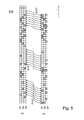
figure 5 illustrates the algorithm for assessing synchronicity of the quantized values. - All the figures are schematic and generally only show parts which are necessary in order to elucidate the invention, wherein other parts may be omitted or merely suggested.
-
Figure 1 shows the acoustic feedback loop commonly present in hands-free communication devices such as computers used for voice-over-IP speaker phones or hands-free telephones. The technical problem to be solved can be exemplified by the case of a telephone call involving one near-end party and one far-end party. Theinput signal 500 is the speech signal spoken by the near-end party. It arrives at the far-end in digital format, and can be in the form of a compressed bit stream.Decoder 211 contains a digital-to-analogue converter that converts the signal to a continuous-time analogue signal. If the signal is compressed thendecoder 211 uses a decoding algorithm to decompress the signal as well.Analogue signal 501 is sent to one ormore speakers 212, which generate anacoustic signal 502 that is subjected to theroom transfer function 213. The modifiedacoustic signal 503 is acquired by themicrophone 214.Microphone 214 may additionally have theinput 504, spoken by the far-end party, and other far-end generated acoustic signals. Theanalogue signal 505 that forms the output of the microphone is sent to encoder 215 that either performs an analogue-to-digital conversion or an analogue-to-digital conversion followed by compression by means of any suitable algorithm. The resultingbit stream 510 is transmitted to the near-end party. - It will be clear to a person skilled in the art that even when
signal 504 is not active (is zero), signal 510 generally differs significantly in amplitude and spectral colouring fromsignal 500, and is delayed. Without appropriate compensation, the near-end party will receive a delayed and distorted copy of the speech signal spoken by him- or herself. This echo that the near-end party hears makes conversation difficult. To remove the problem, echo cancellation and/or suppression is used. The computational effort to perform echo cancellation and suppression is significantly reduced if the delay ofsignal 510 relative to signal 500 is known. The present invention is adapted to estimate the delay between thesignal 500 sent from the near end and thesignal 510 received at the near end, using only signals 500 and 510 as input to the estimation procedure. Echo cancellation and suppression is an important application of the current invention. - Prior to showing a device adapted to perform the inventive method, the underlying method will be described in terms of the information that is received and processed. In an illustrative example, the quantity used for estimating the delay between the signals will be the signal power in different frequency bands. More precisely, the measurement of the
signal 510 at the reference point and the measurement of thesignal 500 at the reception point are modelled, respectively, as functions x(t), y(t) of continuous time. For the purpose of processing, the method will consider time intervals


where w(t) is a window, which advantageously can be chosen to be the Hann window. For discrete-time processing the time integral is replaced by a summation and no integration in frequency is used; q then simply indexes the frequency bins. Similarly, the periodogram of y(t) is η p = (η1, p,η2,p ,...,ηQ,p ), where
For later convenience the term channel is defined to mean the vector ξ q = (ξ q,1,ξ q,2,...,ξ q,P ) and its counterpart for the signal at the reception point. - Fixing thresholds ξ̃1,ξ̃2,...,ξ̃Q, each representing a lowest significant level of signal power, each periodogram is quantized into a binary Q-vector Xp =(X 1, p,X 2,p ,...,XQ,p ), where

Similarly, one fixes thresholds for the other signal to obtain
The thresholds can also be the average channel values, the median channel values or any other quantile value of the channels. A buffer will collect these binary vectors into finite sequences, in other words binary matrices, X = (X 1,...,X K+DM ) and Y = (Y1 ,...,YK ); the constants used in the indices will be defined shortly. - As established above, penalties for each of the four possible co-occurrences are now assigned in accordance with their expected probabilities, which are known a priori by empirical studies or can be estimated with sufficient accuracy. For the exemplary situation described above, the penalties can be chosen as per the fourth column of Table 1, which will be further discussed below. Note that the periodogram values Xq,p and Y q,p , represent, in general, different time intervals. Furthermore, note that it is not necessary for the embodiment to work that a probability distribution can be defined. A strength of the method is that it works even when the statistics of the measurements are time-variant.
Table 1 Xq,p Yq,p' Probability Penalty Penalty, 1st alt. Penalty, 2nd alt. 0 0 0.25 0 1 -0.25 0 1 0.30 0 0 -0.30 1 0 0.05 1 2 -0.05 1 1 0.40 0 -1 -0.40 - It is emphasized that this approach is different from calculating the cross correlation between the two signals. The cross correlation is a function of the time shifts, the maximum of which occurs exactly when the time-shifted signals exhibit the largest degree of likeness. In other words, co-occurrences (1,1) and (0,0) contribute to the value of the cross correlation, whereas co-occurrences (0,1) and (1,0) do not. This simple search for likeness is not suitable in an arbitrary situation. For instance, when the feedback path is nonlinear, cross correlation performs poorly. Moreover, even when the delay varies somewhat over time, the present method will perform well, while cross correlation methods generally will fail due to the lack of a probability distribution that is stable in time.
- M candidate delays D 1 < D 2 < ... < DM , each expressed as a multiple of the distance of consecutive time instants, are then defined. Then the average penalty for each candidate delay is computed. For the qth quantity, the mth candidate delay and with averaging over K time instants, the average penalty is given by

If averaging is performed over K time instants and the longest candidate delay is DM , the binary matrices X and Y are required to have K+DM and K columns, respectively, as indicated above. It is not essential that K time instants are used for calculating Δ q,m for all candidate delays. If in some embodiment it is desirable to use an equal number of columns in the matrices, the method may perform averaging over a smaller number of time instants for the larger candidate delays, so that no extra columns to the right need to be included in X. - The computing of average penalties is schematically illustrated in
figure 5 , which shows matrices X and Y in a case where Q = 3, K = 44 and DM = 4. Each square element corresponds to a matrix entry and its colour illustrates its (Boolean) value. Looking at the patterns one may guess that matrix X is matrix Y delayed (i.e., right-shifted) by 2 units plus some noise, and the inventive method is adapted to return 2 as an estimated delay in this case. Sequences of curved arrows illustrate which columns are to be compared for the candidate delays 2 (denoted by "D=2?"), 3 (denoted by "D=3?"), and 4 (denoted by "D=4?"). The elliptic dots indicate that the sequences of arrows should go on up to the outermost columns, so as to make use of all available information. It is noted that the two rightmost columns in X are not used when the average penalties forcandidate delay 2 are computed. - A particular embodiment of the invention does not compare consecutive pairs of time instants, but compares every other pair, every third pair, etc. Put differently, equation (5) is replaced by a modified average penalty:

where N is an integer defining the spacing of the pairs of time instants to be compared. Instead of having K+DM and K columns, respectively, matrices X and Y then have KN+DM and KN columns. This embodiment is advantageous in virtue of its reduced computational load. - After the full set of average penalties has been determined, weighted sums can be formed as per

where coefficients c 1,c 2,...,cQ preferably reflect the importance attributed to each of the quantities. For instance, if the quantities are audio energies in different frequency bands, a frequency band in the audible range should be given a greater importance, particularly if the energy content of the signal is expected to be relatively high in this frequency band. One may of course achieve a similar effect by summing the average penalties using equal coefficients in (6) provided the penalties of relatively important quantities generally have larger magnitudes than those of relatively less important quantities. - Having produced the weighted sums Δ1,Δ2,...,Δ M , it is now a straightforward matter to find the smallest (signed) value. The corresponding delay among the candidate delays D1,D2,...,DM is the winning one, and will be the best estimate.
- Table 1 above shows two alternative sets of penalties in addition to that discussed in section Summary of the invention, which penalizes the least probable event (1,0) only. As (1,0) is expected to have low probability for the correct delay it is penalized, proportionally to the number of times it occurs. The first alternative set of penalties is simple in so far as the penalties are integer numbers that reflect the unequal counts expected for (0,0), (0,1) and (1,1). Again, as (1,0) should not occur for the correct delay, it is penalized most strongly. The co-occurrences (0,0) and (1,1) are weak indicators that the delay is correct and for this reason receive a negative penalty. Co-occurrence (0,1) does not provide information about the correctness of the candidate delay and therefore is assigned a neutral penalty. It is noted that for the first two penalty sets, knowledge about the probability distribution of the co-occurrences is not required. The second alternative set of penalties in Table 1 consists of the probabilities themselves. For stable statistics, this choice results in a minimum in the average penalty if the observations have the correct probability distribution, that is, if the observations are back-shifted by the correct delay.
- A delay-estimating circuit according to the present invention will now be described with reference to
figure 2 . Twosignals figure 1 , or any other set of signals that form the input and the output of a physical system. More generally, they can be any two signals such that the second contains a delayed copy of the first. - Each of the input signals 510 and 500 is separately pre-processed in
pre-processors vector sequences -
Figure 3 shows the operation of pre-processor 1110 in more detail. Pre-processor 1111 functions similarly. Theinput signal 510 is first segmented into time segments that may overlap in asegmenter 311. Advantageously, the successive segments created bysegmenter 311 are separated in time by 10 ms and the segments have a length of 20 ms. Atransformer 312 performs a windowing and Fourier-transform operation. The output oftransformer 312 is a discrete, short-time complex spectrum.Periodogram computer 313 takes this complex spectrum and applies the absolute operator to each spectrum component and squares the results to render aperiodogram 512, which is a short-term power spectrum estimate. The periodogram is a vector property of the signal segment that is the output ofsegmenter 311. - Returning to
figure 2 , the specifyingcircuit 112 stores what subset of channels is to be used for delay estimation. Thus, the specifyingcircuit 112 specifies the active channels. Specifyingcircuit 112 also stores the thresholds that are to be applied to the active channels. A first andsecond threshold circuit specifier 112. - Advantageously, and as an innovative part of the present invention, each of the vectors of vector signals 514 and 515 can be stored in a single digital integer number, reducing storage requirements on most computing devices significantly. This approach is particularly efficient if 32 or 64 channels are active, as the combined hardware and software on many computing devices are adapted to handle 32- and 64-bit integers. Note also that this method of using integers to denote the one-bit quantization index facilitates generalization for multiple thresholds The output is then an index that requires for m thresholds log2 (m+1) bits to be described. Thus each vector has log2 (m+1) bit planes that each can be described by an integer. Below, a bit vector written in the form of a single integer (one-bit quantization) will be called a spectral integer. However, it is understood that in certain applications and for certain channel numbers, bit vectors are used without being stored as spectral integers.
-
Buffer specifier 114 specifies the length of a first andsecond shift register second shift register 1151 can be shorter than thefirst shift register 1150. Thus, the buffer specifier specifies how many spectral integers are stored inshift registers buffer specifier 114. Advantageously this age is the same for all channels insignal 514 and, separately, for all channels insignal 515. - The actual age used depends on the signal that the delay is estimated for. If the delay is constant, the accuracy of the delay estimate increases with the length of the buffer. If the delay is changing, then an age that is a good compromise for the rate of change of the delay must be selected. In this embodiment this is determined by a designer of the system, but automated procedures can also be used for this purpose. As seen above, the lengths of the buffers can be calculated on the basis of the largest candidate delay, the desired number of time instants to be compared and, when applicable, their consecutive spacing.
- A
delay assessment circuit 118, which can be implemented in a number of different ways, is adapted to calculate the average penalty for each candidate delay. In the conceptually simplest implementation, thedelay assessment circuit 118 receives theentire buffer content buffers assessment circuit 118 outputs a signal indicative of the estimated delay (518). -
Figure 4 illustrates an embodiment of amethod 400 according to the invention for estimating the delay of a signal between a reference point and a reception point.Figure 4 is a flowchart depicting the steps of the method in the case of three quantities and five candidate delays. Instep 410, the three quantities are defined. Next, instep 412, each of the quantities is evaluated at the reference point and the reception point at a plurality of time instants. Instep 414, the values of the three quantities are quantized by comparison with thresholds. The thresholds are time-invariant in the sense that for each quantity, an equal threshold is used for all time instances. Subsequently, instep 416, the most recent quantized values are stored. A penalty is assigned to each of the possible ordered pairs of simultaneous quantized values; this isstep 418. Instep 420, a set of five candidate delays are defined. Then, instep 422, an average penalty is computed for each candidate delay. The average is based on the three quantities and a plurality of pairs of quantized values. Finally, instep 424, an estimate delay is elected from the set of candidate delays on the basis of the computed average penalties. It is noted thatstep 418 may be performed at any instant after thestep 410 of defining the quantities and before thestep 422 of computing an average penalty. - While the invention has been illustrated and described in detail in the drawings and foregoing description, such illustration and description are to be considered illustrative or exemplary and not restrictive; the invention is not limited to the disclosed embodiment. It is understood that some components that are included in the disclosed embodiments are optional. For example, decoders and encoders may not be present if the invention is embodied in a public telephone network according to older standards.
- Other variations to the disclosed embodiments can be understood and effected by those skilled in the art in practicing the claimed invention, from a study of the drawings, the disclosure, and the appended claims. The mere fact that certain measures are recited in mutually different dependent claims does not indicate that a combination of these measured cannot be used to advantage. Any reference signs in the claims should not be construed as limiting the scope.
-
- 1. A method for estimating a delay of a signal between a reference point and a reception point, including the steps of:
- defining at least one quantity;
- for each quantity, evaluating the quantity at the reference point (510) and reception point at a plurality of time instants;
- quantizing the values of said at least one quantity by comparing values originating from the reference point with a first time-invariant threshold and values originating from the reception point with a second time-invariant threshold, thereby yielding quantized values (514, 515);
- storing the Z most recent quantized values (516, 517), where Z is a predetermined number;
- for each quantity, based on the expected behaviour of the quantity, assigning a penalty to each of all possible ordered pairs of simultaneous quantized values of the quantity which are evaluated simultaneously at the reference and the reception point;
- defining a set of candidate delays;
- for each candidate delay, computing an average penalty over a plurality of pairs of quantized values, each pair consisting of a stored quantized first value of a quantity evaluated at the reference point and a stored quantized second value of the same quantity evaluated at the same or a later time instant at the reception point, wherein the first and the second values are separated by the candidate delay; and
- electing an estimated delay (518) from the set of candidate delays based on the computed average penalties.
- 2. A method according to item 1, wherein a first constant penalty is assigned, for a particular quantity, to the co-occurrence of a high quantized reference-point value and a low quantized reception-point value, and a second penalty is assigned to all other occurrences, wherein the first penalty is greater than the second penalty.
- 3. A method according to
item 2, wherein said particular quantity is the signal power in a predetermined frequency band. - 4. A method according to any one of the preceding items , wherein at least one quantity is chosen from a group including:
- a component in an encoded audio or video format,
- a power of the signal in a predetermined frequency band,
- an absolute value of the signal,
- an amplitude of the signal,
- an amplitude of the signal envelope,
- an integral over time of the absolute value of the signal, and
- an integral over time of the absolute value of the time derivative of the signal.
- 5. A method according to any of the preceding items , wherein the step of quantizing further comprises comparing values of said at least one quantity with at least one further time-invariant threshold, thereby yielding multi-bit quantized values.
- 6. A method according to item 5, wherein the number of further time-invariant thresholds is at most 20.
- 7. A device for estimating a delay of a signal between a reference point (510) and a reception point (500), including:
- a first and a second pre-processor (1110, 1111) for evaluating, at a plurality of time instants, at least one quantity from the signal at the reference point (510) and at the reception point (500), respectively;
- a first and a second threshold circuit (1130, 1131) for quantizing values (512, 513) of said at least one quantity with respect to a first and a second threshold, which values are received from said first and second pre-processor (1110, 1111), respectively;
- a first and a second shift register (1150, 1151) for storing the most recent values of the quantized values (514, 515) of said at least one property, which quantized values are received from said first and second threshold circuit (1130, 1131); and
- a delay assessment circuit (118) for comparing stored quantized values (516, 517) received from said first and second shift register (1150, 1151), wherein a predetermined penalty is associated with each of all possible ordered pairs of simultaneous quantized values, said circuit (118) being configured for:
- computing, for each candidate delay in a set of candidate delays, an average penalty over a plurality of pairs of quantized values, each pair consisting of a first quantized value (516) of a quantity evaluated at the reference point and a second quantized value (517) of the same quantity evaluated at the same or a later time instant at the reception point, wherein the first and second values are separated by the candidate delay; and
- electing an estimated delay (518) from the set of candidate delays based on the computed average penalties.
- 8. A device according item 7, further comprising a specifying circuit (112) for providing said first and second threshold circuit (1130, 1131) with said first and second threshold, respectively.
- 9. A device according to item 7 or 8, wherein said threshold circuit is adapted to quantize values (512, 513) of said at least one quantity with respect to at least one further first threshold and, respectively, with respect to at least one further second threshold.
- 10. A device according to any one of items 7-9, wherein the reference point (500) and the reception point (510) are located in a communications system.
- 11. A device according to any one of items 7-10, wherein said at least one quantity is a momentary value.
- 12. A device according to any one of items 7-10, wherein said at least one quantity is averaged, for each time instant, over a finite time interval.
- 13. A device according to item 12, wherein two of said intervals overlap in time.
- 14. A device according to item 12 or 13, wherein the lengths of said intervals are between 50 and 1000 milliseconds.
- 15. An echo-cancelling circuit including a device according to any one of items 7-14.
Claims (15)
- A method for estimating a delay of a signal between a reference point and a reception point, the method comprising the steps of:evaluating a quantity of the signal at the reference point and at the reception point at a plurality of time instants, thereby yielding reference-point values and reception-point values, respectively;comparing each of said reference-point values with a first time-invariant threshold and comparing each of said reception-point values with a second time-invariant threshold, thereby yielding quantized reference-point values and quantized reception-point values, respectively;assigning a penalty to each of all possible pairs of quantized values based on an expected probability of simultaneous occurrence of the values of said pair when the delay is correctly estimated;computing a weighted penalty for each candidate delay from a set of candidate delays, each weighted penalty being an average penalty computed for the candidate delay with a weighting term assigned based on the particular quantity; andelecting an estimated delay from the set of candidate delays based on the computed weighted penalties.
- A method according to claim 1, wherein a first constant penalty is assigned, for a particular quantity, to the simultaneous occurrence of a high quantized reference-point value and a low quantized reception-point value, and a second penalty is assigned to all other occurrences, wherein the first penalty is greater than the second penalty.
- A method according to claim 1, wherein said particular quantity is the signal power in a predetermined frequency band.
- A method according to claim 1, wherein evaluating the quantity of said signal includes evaluating at least one of a component in an encoded audio or video format, a power of the signal in a predetermined frequency band, an absolute value of the signal, an amplitude of the signal, an amplitude of the signal envelope, an integral over time of the absolute value of the signal, and an integral over time of the absolute value of the time derivative of the signal.
- A method according to claim 1, wherein the step of comparing further comprises comparing values of said quantity with at least one further time-invariant threshold, thereby yielding multi-bit quantized values.
- A method according to claim 5, wherein the number of further time-invariant thresholds is at most 20.
- A device for estimating a delay of a signal between a reference point and a reception point, comprising:a first and a second pre-processor for evaluating, at a plurality of time instants, at least one quantity from the signal at the reference point and at the reception point to yield reference-point values and reception-point values, respectively;a first and a second threshold circuit for quantizing said reference-point values with respect to a first threshold and said reception-point values with respect to a second threshold, which values are received from said first and second pre-processor, respectively; anda delay assessment circuit for receiving the quantized values, wherein a penalty is associated with each of all possible pairs of quantized values based on the expected probability of simultaneous occurrence of the values of said pair when the delay is correctly estimated, and said delay assessment circuit being configured for:computing, for each candidate delay in a set of candidate delays, a weighted penalty by averaging the penalties of a plurality of pairs of quantized values and assigning a weighting term based on the particular quantity; andelecting an estimated delay from the set of candidate delays based on the computed weighted penalties.
- A device according to claim 7, further comprising:a specifying circuit for providing said first and second threshold circuit with said first and second thresholds, respectively.
- A device according to claim 7, wherein each of said first and second threshold circuit is configured to quantize values of said at least one quantity with respect to at least one further first threshold and, respectively, with respect to at least one further second threshold.
- A device according to claim 7, wherein the reference point and the reception point are located in a communications system.
- A device according to claim 7, wherein said at least one quantity is a momentary value.
- A device according to claim 7, wherein said at least one quantity is averaged, for each time instant, over a finite time interval.
- A device according to claim 12, wherein two of said intervals overlap in time.
- A device according to claim 13, wherein the lengths of said intervals are between 50 and 1000 milliseconds.
- An echo-cancelling circuit including a device according to claim 13.
Priority Applications (1)
| Application Number | Priority Date | Filing Date | Title |
|---|---|---|---|
| EP20120183421 EP2533511B1 (en) | 2008-12-12 | 2008-12-12 | Delay Estimator |
Applications Claiming Priority (3)
| Application Number | Priority Date | Filing Date | Title |
|---|---|---|---|
| EP11163189.1A EP2352274B1 (en) | 2008-12-12 | 2008-12-12 | Delay estimator |
| EP08171468A EP2197190B1 (en) | 2008-12-12 | 2008-12-12 | Delay estimator |
| EP20120183421 EP2533511B1 (en) | 2008-12-12 | 2008-12-12 | Delay Estimator |
Related Parent Applications (5)
| Application Number | Title | Priority Date | Filing Date |
|---|---|---|---|
| EP08171468A Division EP2197190B1 (en) | 2008-12-12 | 2008-12-12 | Delay estimator |
| EP11163189.1A Division-Into EP2352274B1 (en) | 2008-12-12 | 2008-12-12 | Delay estimator |
| EP11163189.1A Division EP2352274B1 (en) | 2008-12-12 | 2008-12-12 | Delay estimator |
| EP08171468.5 Division | 2008-12-12 | ||
| EP11163189.1 Division | 2011-04-20 |
Publications (2)
| Publication Number | Publication Date |
|---|---|
| EP2533511A1 true EP2533511A1 (en) | 2012-12-12 |
| EP2533511B1 EP2533511B1 (en) | 2015-04-22 |
Family
ID=40432396
Family Applications (3)
| Application Number | Title | Priority Date | Filing Date |
|---|---|---|---|
| EP20120183421 Active EP2533511B1 (en) | 2008-12-12 | 2008-12-12 | Delay Estimator |
| EP11163189.1A Active EP2352274B1 (en) | 2008-12-12 | 2008-12-12 | Delay estimator |
| EP08171468A Not-in-force EP2197190B1 (en) | 2008-12-12 | 2008-12-12 | Delay estimator |
Family Applications After (2)
| Application Number | Title | Priority Date | Filing Date |
|---|---|---|---|
| EP11163189.1A Active EP2352274B1 (en) | 2008-12-12 | 2008-12-12 | Delay estimator |
| EP08171468A Not-in-force EP2197190B1 (en) | 2008-12-12 | 2008-12-12 | Delay estimator |
Country Status (7)
| Country | Link |
|---|---|
| US (2) | US8320552B2 (en) |
| EP (3) | EP2533511B1 (en) |
| CN (1) | CN102318328B (en) |
| AT (1) | ATE508579T1 (en) |
| CA (1) | CA2746794C (en) |
| DE (1) | DE602008006754D1 (en) |
| WO (1) | WO2010066496A1 (en) |
Families Citing this family (9)
| Publication number | Priority date | Publication date | Assignee | Title |
|---|---|---|---|---|
| US8718275B2 (en) | 2011-12-22 | 2014-05-06 | Google Inc. | Low complex and robust delay estimation |
| KR20150002784A (en) * | 2012-06-08 | 2015-01-07 | 인텔 코포레이션 | Echo cancellation algorithm for long delayed echo |
| GB2525051B (en) | 2014-09-30 | 2016-04-13 | Imagination Tech Ltd | Detection of acoustic echo cancellation |
| US9888330B1 (en) * | 2016-07-28 | 2018-02-06 | Getgo, Inc. | Detecting signal processing component failure using one or more delay estimators |
| CN108664424B (en) * | 2017-03-30 | 2020-06-23 | 炬芯(珠海)科技有限公司 | Method and equipment for determining optimal delay |
| US12278749B2 (en) | 2020-02-07 | 2025-04-15 | Juniper Networks, Inc. | Method and system for estimating communication latency |
| US12284100B2 (en) * | 2022-02-09 | 2025-04-22 | Mellanox Technologies, Ltd. | Network delay estimation |
| CN116230005B (en) * | 2023-03-06 | 2024-08-02 | 长沙东玛克信息科技有限公司 | Remote voice signal delay estimation method |
| CN119322443A (en) * | 2024-09-03 | 2025-01-17 | 国网江苏省电力有限公司灌云县供电分公司 | Global fractional order nonsingular terminal sliding mode control method of snake-shaped robot |
Citations (1)
| Publication number | Priority date | Publication date | Assignee | Title |
|---|---|---|---|---|
| WO1995017784A1 (en) | 1993-12-23 | 1995-06-29 | Nokia Telecommunications Oy | Method for determining the location of echo in an echo cancellar |
Family Cites Families (11)
| Publication number | Priority date | Publication date | Assignee | Title |
|---|---|---|---|---|
| WO1994000577A1 (en) | 1992-06-30 | 1994-01-06 | Smithkline Beecham P.L.C. | D-n-carbamoyl-amino acid amidohydrolase and hydantoinase |
| US5959500A (en) * | 1998-01-26 | 1999-09-28 | Glenayre Electronics, Inc. | Model-based adaptive feedforward amplifier linearizer |
| US6324170B1 (en) * | 1998-09-10 | 2001-11-27 | Nortel Networks Limited | Echo controller with compensation for variable delay networks |
| US6859531B1 (en) * | 2000-09-15 | 2005-02-22 | Intel Corporation | Residual echo estimation for echo cancellation |
| US20040252652A1 (en) * | 2003-06-10 | 2004-12-16 | Alexander Berestesky | Cross correlation, bulk delay estimation, and echo cancellation |
| US6961862B2 (en) * | 2004-03-17 | 2005-11-01 | Rambus, Inc. | Drift tracking feedback for communication channels |
| US7444268B1 (en) * | 2004-03-25 | 2008-10-28 | Sun Microsystems, Inc. | Method and apparatus for identifying a drift in a quantized signal in a computer system |
| CN1691716A (en) * | 2004-04-23 | 2005-11-02 | 北京三星通信技术研究有限公司 | echo canceller |
| US7912158B2 (en) * | 2005-11-08 | 2011-03-22 | Navcom Technology, Inc. | Sampling threshold and gain for satellite navigation receiver |
| CN101026659B (en) * | 2006-02-23 | 2010-04-07 | 中兴通讯股份有限公司 | A Realization Method of Echo Delay Location |
| US8213598B2 (en) * | 2008-02-26 | 2012-07-03 | Microsoft Corporation | Harmonic distortion residual echo suppression |
-
2008
- 2008-12-12 EP EP20120183421 patent/EP2533511B1/en active Active
- 2008-12-12 DE DE602008006754T patent/DE602008006754D1/en active Active
- 2008-12-12 AT AT08171468T patent/ATE508579T1/en not_active IP Right Cessation
- 2008-12-12 EP EP11163189.1A patent/EP2352274B1/en active Active
- 2008-12-12 EP EP08171468A patent/EP2197190B1/en not_active Not-in-force
-
2009
- 2009-10-20 CA CA2746794A patent/CA2746794C/en active Active
- 2009-10-20 CN CN2009801566112A patent/CN102318328B/en active Active
- 2009-10-20 WO PCT/EP2009/063707 patent/WO2010066496A1/en not_active Ceased
- 2009-10-20 US US13/139,267 patent/US8320552B2/en active Active
-
2011
- 2011-09-26 US US13/245,528 patent/US8290143B2/en active Active
Patent Citations (1)
| Publication number | Priority date | Publication date | Assignee | Title |
|---|---|---|---|---|
| WO1995017784A1 (en) | 1993-12-23 | 1995-06-29 | Nokia Telecommunications Oy | Method for determining the location of echo in an echo cancellar |
Also Published As
| Publication number | Publication date |
|---|---|
| CN102318328A (en) | 2012-01-11 |
| EP2352274A2 (en) | 2011-08-03 |
| CA2746794A1 (en) | 2010-06-17 |
| EP2197190A1 (en) | 2010-06-16 |
| EP2352274B1 (en) | 2018-02-14 |
| US8290143B2 (en) | 2012-10-16 |
| US8320552B2 (en) | 2012-11-27 |
| EP2352274A3 (en) | 2011-08-24 |
| DE602008006754D1 (en) | 2011-06-16 |
| CA2746794C (en) | 2015-02-24 |
| EP2197190B1 (en) | 2011-05-04 |
| US20110249810A1 (en) | 2011-10-13 |
| US20120063572A1 (en) | 2012-03-15 |
| CN102318328B (en) | 2013-12-18 |
| WO2010066496A1 (en) | 2010-06-17 |
| EP2533511B1 (en) | 2015-04-22 |
| ATE508579T1 (en) | 2011-05-15 |
Similar Documents
| Publication | Publication Date | Title |
|---|---|---|
| US8290143B2 (en) | Delay estimator | |
| CN101719969B (en) | Method and system for judging double-end conversation and method and system for eliminating echo | |
| US8718275B2 (en) | Low complex and robust delay estimation | |
| EP2912833B1 (en) | System and method for acoustic echo cancellation | |
| US8594173B2 (en) | Method for determining updated filter coefficients of an adaptive filter adapted by an LMS algorithm with pre-whitening | |
| CN102959625B9 (en) | Method and apparatus for adaptively detecting voice activity in input audio signal | |
| US20150003606A1 (en) | Detecting and quantifying non-linear characteristics of audio signals | |
| Rix | Perceptual speech quality assessment-a review | |
| EP1958341B1 (en) | Echo detection | |
| Kubichek et al. | Advances in objective voice quality assessment | |
| US20020093919A1 (en) | Fast converging affine projection based echo canceller for sparse multi-path channels | |
| TWI234941B (en) | Echo canceler, article of manufacture, and method and system for canceling echo | |
| US8009825B2 (en) | Signal processing | |
| JP5952252B2 (en) | Call quality estimation method, call quality estimation device, and program | |
| US7606315B2 (en) | Line sensor selection for quantifying alien crosstalk in a shared communications medium | |
| CN1607740B (en) | Modified affine projection algorithm for non-stationary signal | |
| Ding et al. | Nonintrusive measurement of echo-path parameters in VoIP environments | |
| Kothandaraman et al. | Acoustic Echo Cancellation Using PEVD Based Adaptive Kalman Filter. | |
| EP2223522B1 (en) | Non linear acoustic feedback suppression in a telephone device | |
| Osaka et al. | Objective evaluation model of telephone transmission performance for fundamental transmission factors | |
| WO2023218600A1 (en) | Call quality evaluation device, call quality evaluation method, and program | |
| Furuhashi et al. | Realization of nonlinear acoustic echo cancellation by subband parallel cascade Volterra filter | |
| Trump | Detection of echo generated in mobile phones | |
| Trump | Detection of echo generated in mobile phones using pitch distance | |
| Fricsson | Detection of echo generated in mobile phones |
Legal Events
| Date | Code | Title | Description |
|---|---|---|---|
| PUAI | Public reference made under article 153(3) epc to a published international application that has entered the european phase |
Free format text: ORIGINAL CODE: 0009012 |
|
| 17P | Request for examination filed |
Effective date: 20120907 |
|
| AC | Divisional application: reference to earlier application |
Ref document number: 2352274 Country of ref document: EP Kind code of ref document: P Ref document number: 2197190 Country of ref document: EP Kind code of ref document: P |
|
| AK | Designated contracting states |
Kind code of ref document: A1 Designated state(s): AT BE BG CH CY CZ DE DK EE ES FI FR GB GR HR HU IE IS IT LI LT LU LV MC MT NL NO PL PT RO SE SI SK TR |
|
| 17Q | First examination report despatched |
Effective date: 20140107 |
|
| GRAP | Despatch of communication of intention to grant a patent |
Free format text: ORIGINAL CODE: EPIDOSNIGR1 |
|
| INTG | Intention to grant announced |
Effective date: 20141219 |
|
| GRAS | Grant fee paid |
Free format text: ORIGINAL CODE: EPIDOSNIGR3 |
|
| GRAA | (expected) grant |
Free format text: ORIGINAL CODE: 0009210 |
|
| AC | Divisional application: reference to earlier application |
Ref document number: 2352274 Country of ref document: EP Kind code of ref document: P Ref document number: 2197190 Country of ref document: EP Kind code of ref document: P |
|
| AK | Designated contracting states |
Kind code of ref document: B1 Designated state(s): AT BE BG CH CY CZ DE DK EE ES FI FR GB GR HR HU IE IS IT LI LT LU LV MC MT NL NO PL PT RO SE SI SK TR |
|
| REG | Reference to a national code |
Ref country code: GB Ref legal event code: FG4D |
|
| REG | Reference to a national code |
Ref country code: CH Ref legal event code: EP |
|
| REG | Reference to a national code |
Ref country code: AT Ref legal event code: REF Ref document number: 723830 Country of ref document: AT Kind code of ref document: T Effective date: 20150515 |
|
| REG | Reference to a national code |
Ref country code: IE Ref legal event code: FG4D |
|
| REG | Reference to a national code |
Ref country code: DE Ref legal event code: R096 Ref document number: 602008037872 Country of ref document: DE Effective date: 20150603 |
|
| REG | Reference to a national code |
Ref country code: NL Ref legal event code: VDEP Effective date: 20150422 |
|
| REG | Reference to a national code |
Ref country code: AT Ref legal event code: MK05 Ref document number: 723830 Country of ref document: AT Kind code of ref document: T Effective date: 20150422 |
|
| REG | Reference to a national code |
Ref country code: LT Ref legal event code: MG4D |
|
| PG25 | Lapsed in a contracting state [announced via postgrant information from national office to epo] |
Ref country code: NL Free format text: LAPSE BECAUSE OF FAILURE TO SUBMIT A TRANSLATION OF THE DESCRIPTION OR TO PAY THE FEE WITHIN THE PRESCRIBED TIME-LIMIT Effective date: 20150422 |
|
| PG25 | Lapsed in a contracting state [announced via postgrant information from national office to epo] |
Ref country code: ES Free format text: LAPSE BECAUSE OF FAILURE TO SUBMIT A TRANSLATION OF THE DESCRIPTION OR TO PAY THE FEE WITHIN THE PRESCRIBED TIME-LIMIT Effective date: 20150422 Ref country code: PT Free format text: LAPSE BECAUSE OF FAILURE TO SUBMIT A TRANSLATION OF THE DESCRIPTION OR TO PAY THE FEE WITHIN THE PRESCRIBED TIME-LIMIT Effective date: 20150824 Ref country code: NO Free format text: LAPSE BECAUSE OF FAILURE TO SUBMIT A TRANSLATION OF THE DESCRIPTION OR TO PAY THE FEE WITHIN THE PRESCRIBED TIME-LIMIT Effective date: 20150722 Ref country code: LT Free format text: LAPSE BECAUSE OF FAILURE TO SUBMIT A TRANSLATION OF THE DESCRIPTION OR TO PAY THE FEE WITHIN THE PRESCRIBED TIME-LIMIT Effective date: 20150422 Ref country code: HR Free format text: LAPSE BECAUSE OF FAILURE TO SUBMIT A TRANSLATION OF THE DESCRIPTION OR TO PAY THE FEE WITHIN THE PRESCRIBED TIME-LIMIT Effective date: 20150422 Ref country code: FI Free format text: LAPSE BECAUSE OF FAILURE TO SUBMIT A TRANSLATION OF THE DESCRIPTION OR TO PAY THE FEE WITHIN THE PRESCRIBED TIME-LIMIT Effective date: 20150422 |
|
| PG25 | Lapsed in a contracting state [announced via postgrant information from national office to epo] |
Ref country code: GR Free format text: LAPSE BECAUSE OF FAILURE TO SUBMIT A TRANSLATION OF THE DESCRIPTION OR TO PAY THE FEE WITHIN THE PRESCRIBED TIME-LIMIT Effective date: 20150723 Ref country code: IS Free format text: LAPSE BECAUSE OF FAILURE TO SUBMIT A TRANSLATION OF THE DESCRIPTION OR TO PAY THE FEE WITHIN THE PRESCRIBED TIME-LIMIT Effective date: 20150822 Ref country code: LV Free format text: LAPSE BECAUSE OF FAILURE TO SUBMIT A TRANSLATION OF THE DESCRIPTION OR TO PAY THE FEE WITHIN THE PRESCRIBED TIME-LIMIT Effective date: 20150422 Ref country code: AT Free format text: LAPSE BECAUSE OF FAILURE TO SUBMIT A TRANSLATION OF THE DESCRIPTION OR TO PAY THE FEE WITHIN THE PRESCRIBED TIME-LIMIT Effective date: 20150422 |
|
| REG | Reference to a national code |
Ref country code: FR Ref legal event code: PLFP Year of fee payment: 8 |
|
| REG | Reference to a national code |
Ref country code: DE Ref legal event code: R097 Ref document number: 602008037872 Country of ref document: DE |
|
| PG25 | Lapsed in a contracting state [announced via postgrant information from national office to epo] |
Ref country code: EE Free format text: LAPSE BECAUSE OF FAILURE TO SUBMIT A TRANSLATION OF THE DESCRIPTION OR TO PAY THE FEE WITHIN THE PRESCRIBED TIME-LIMIT Effective date: 20150422 Ref country code: DK Free format text: LAPSE BECAUSE OF FAILURE TO SUBMIT A TRANSLATION OF THE DESCRIPTION OR TO PAY THE FEE WITHIN THE PRESCRIBED TIME-LIMIT Effective date: 20150422 |
|
| PLBE | No opposition filed within time limit |
Free format text: ORIGINAL CODE: 0009261 |
|
| STAA | Information on the status of an ep patent application or granted ep patent |
Free format text: STATUS: NO OPPOSITION FILED WITHIN TIME LIMIT |
|
| PG25 | Lapsed in a contracting state [announced via postgrant information from national office to epo] |
Ref country code: CZ Free format text: LAPSE BECAUSE OF FAILURE TO SUBMIT A TRANSLATION OF THE DESCRIPTION OR TO PAY THE FEE WITHIN THE PRESCRIBED TIME-LIMIT Effective date: 20150422 Ref country code: RO Free format text: LAPSE BECAUSE OF NON-PAYMENT OF DUE FEES Effective date: 20150422 Ref country code: PL Free format text: LAPSE BECAUSE OF FAILURE TO SUBMIT A TRANSLATION OF THE DESCRIPTION OR TO PAY THE FEE WITHIN THE PRESCRIBED TIME-LIMIT Effective date: 20150422 Ref country code: SK Free format text: LAPSE BECAUSE OF FAILURE TO SUBMIT A TRANSLATION OF THE DESCRIPTION OR TO PAY THE FEE WITHIN THE PRESCRIBED TIME-LIMIT Effective date: 20150422 |
|
| 26N | No opposition filed |
Effective date: 20160125 |
|
| PG25 | Lapsed in a contracting state [announced via postgrant information from national office to epo] |
Ref country code: IT Free format text: LAPSE BECAUSE OF FAILURE TO SUBMIT A TRANSLATION OF THE DESCRIPTION OR TO PAY THE FEE WITHIN THE PRESCRIBED TIME-LIMIT Effective date: 20150422 |
|
| PG25 | Lapsed in a contracting state [announced via postgrant information from national office to epo] |
Ref country code: SI Free format text: LAPSE BECAUSE OF FAILURE TO SUBMIT A TRANSLATION OF THE DESCRIPTION OR TO PAY THE FEE WITHIN THE PRESCRIBED TIME-LIMIT Effective date: 20150422 Ref country code: BE Free format text: LAPSE BECAUSE OF NON-PAYMENT OF DUE FEES Effective date: 20151231 |
|
| PG25 | Lapsed in a contracting state [announced via postgrant information from national office to epo] |
Ref country code: MC Free format text: LAPSE BECAUSE OF FAILURE TO SUBMIT A TRANSLATION OF THE DESCRIPTION OR TO PAY THE FEE WITHIN THE PRESCRIBED TIME-LIMIT Effective date: 20150422 Ref country code: LU Free format text: LAPSE BECAUSE OF FAILURE TO SUBMIT A TRANSLATION OF THE DESCRIPTION OR TO PAY THE FEE WITHIN THE PRESCRIBED TIME-LIMIT Effective date: 20151212 |
|
| REG | Reference to a national code |
Ref country code: CH Ref legal event code: PL |
|
| PG25 | Lapsed in a contracting state [announced via postgrant information from national office to epo] |
Ref country code: BE Free format text: LAPSE BECAUSE OF FAILURE TO SUBMIT A TRANSLATION OF THE DESCRIPTION OR TO PAY THE FEE WITHIN THE PRESCRIBED TIME-LIMIT Effective date: 20150422 |
|
| REG | Reference to a national code |
Ref country code: IE Ref legal event code: MM4A |
|
| PG25 | Lapsed in a contracting state [announced via postgrant information from national office to epo] |
Ref country code: CH Free format text: LAPSE BECAUSE OF NON-PAYMENT OF DUE FEES Effective date: 20151231 Ref country code: IE Free format text: LAPSE BECAUSE OF NON-PAYMENT OF DUE FEES Effective date: 20151212 Ref country code: LI Free format text: LAPSE BECAUSE OF NON-PAYMENT OF DUE FEES Effective date: 20151231 |
|
| REG | Reference to a national code |
Ref country code: FR Ref legal event code: PLFP Year of fee payment: 9 |
|
| PG25 | Lapsed in a contracting state [announced via postgrant information from national office to epo] |
Ref country code: HU Free format text: LAPSE BECAUSE OF FAILURE TO SUBMIT A TRANSLATION OF THE DESCRIPTION OR TO PAY THE FEE WITHIN THE PRESCRIBED TIME-LIMIT; INVALID AB INITIO Effective date: 20081212 Ref country code: BG Free format text: LAPSE BECAUSE OF FAILURE TO SUBMIT A TRANSLATION OF THE DESCRIPTION OR TO PAY THE FEE WITHIN THE PRESCRIBED TIME-LIMIT Effective date: 20150422 |
|
| PG25 | Lapsed in a contracting state [announced via postgrant information from national office to epo] |
Ref country code: SE Free format text: LAPSE BECAUSE OF FAILURE TO SUBMIT A TRANSLATION OF THE DESCRIPTION OR TO PAY THE FEE WITHIN THE PRESCRIBED TIME-LIMIT Effective date: 20150422 Ref country code: CY Free format text: LAPSE BECAUSE OF FAILURE TO SUBMIT A TRANSLATION OF THE DESCRIPTION OR TO PAY THE FEE WITHIN THE PRESCRIBED TIME-LIMIT Effective date: 20150422 |
|
| PG25 | Lapsed in a contracting state [announced via postgrant information from national office to epo] |
Ref country code: MT Free format text: LAPSE BECAUSE OF FAILURE TO SUBMIT A TRANSLATION OF THE DESCRIPTION OR TO PAY THE FEE WITHIN THE PRESCRIBED TIME-LIMIT Effective date: 20150422 |
|
| REG | Reference to a national code |
Ref country code: FR Ref legal event code: PLFP Year of fee payment: 10 |
|
| REG | Reference to a national code |
Ref country code: DE Ref legal event code: R082 Ref document number: 602008037872 Country of ref document: DE Representative=s name: SPLANEMANN PATENTANWAELTE PARTNERSCHAFT MBB, DE Ref country code: DE Ref legal event code: R081 Ref document number: 602008037872 Country of ref document: DE Owner name: GOOGLE LLC (N.D.GES.D. STAATES DELAWARE), MOUN, US Free format text: FORMER OWNER: GOOGLE, INC., MOUNTAIN VIEW, CALIF., US |
|
| REG | Reference to a national code |
Ref country code: FR Ref legal event code: CD Owner name: GOOGLE INC., US Effective date: 20180213 Ref country code: FR Ref legal event code: CJ Effective date: 20180213 |
|
| PG25 | Lapsed in a contracting state [announced via postgrant information from national office to epo] |
Ref country code: TR Free format text: LAPSE BECAUSE OF FAILURE TO SUBMIT A TRANSLATION OF THE DESCRIPTION OR TO PAY THE FEE WITHIN THE PRESCRIBED TIME-LIMIT Effective date: 20150422 |
|
| P01 | Opt-out of the competence of the unified patent court (upc) registered |
Effective date: 20230505 |
|
| PGFP | Annual fee paid to national office [announced via postgrant information from national office to epo] |
Ref country code: GB Payment date: 20231227 Year of fee payment: 16 |
|
| PGFP | Annual fee paid to national office [announced via postgrant information from national office to epo] |
Ref country code: FR Payment date: 20231227 Year of fee payment: 16 |
|
| GBPC | Gb: european patent ceased through non-payment of renewal fee |
Effective date: 20241212 |
|
| PG25 | Lapsed in a contracting state [announced via postgrant information from national office to epo] |
Ref country code: GB Free format text: LAPSE BECAUSE OF NON-PAYMENT OF DUE FEES Effective date: 20241212 |
|
| PG25 | Lapsed in a contracting state [announced via postgrant information from national office to epo] |
Ref country code: FR Free format text: LAPSE BECAUSE OF NON-PAYMENT OF DUE FEES Effective date: 20241231 |
|
| PGFP | Annual fee paid to national office [announced via postgrant information from national office to epo] |
Ref country code: DE Payment date: 20251229 Year of fee payment: 18 |