EP2533508A1 - Sip terminal control system and sip terminal control method - Google Patents
Sip terminal control system and sip terminal control method Download PDFInfo
- Publication number
- EP2533508A1 EP2533508A1 EP11736892A EP11736892A EP2533508A1 EP 2533508 A1 EP2533508 A1 EP 2533508A1 EP 11736892 A EP11736892 A EP 11736892A EP 11736892 A EP11736892 A EP 11736892A EP 2533508 A1 EP2533508 A1 EP 2533508A1
- Authority
- EP
- European Patent Office
- Prior art keywords
- main device
- sip
- sections
- slave
- master
- Prior art date
- Legal status (The legal status is an assumption and is not a legal conclusion. Google has not performed a legal analysis and makes no representation as to the accuracy of the status listed.)
- Granted
Links
Images

Classifications
-
- H—ELECTRICITY
- H04—ELECTRIC COMMUNICATION TECHNIQUE
- H04L—TRANSMISSION OF DIGITAL INFORMATION, e.g. TELEGRAPHIC COMMUNICATION
- H04L65/00—Network arrangements, protocols or services for supporting real-time applications in data packet communication
- H04L65/1066—Session management
- H04L65/1101—Session protocols
- H04L65/1104—Session initiation protocol [SIP]
Definitions
- the present invention relates to an SIP terminal control system and an SIP terminal control method in a system including a master main device and one or more slave main devices.
- a physical package included in a slave main device is used as a package for controlling a digital terminal and a digital line.
- the physical package included in the slave main device uses a correspondence table to be associated with a virtual slot included in a master main device.
- the master main device utilizes the association to thereby control the digital terminal and digital line which are connected with the physical package of the slave main device.
- the physical package included in each slave main device uses a CPU of the corresponding slave main device to control the digital terminal and the like, so that processing for such control can be avoided from being concentrated on a CPU of the master main device.
- SIP terminals can be also connected to the system including the master main device and one or more slave main devices. As such, versatility and availability of this system can be enhanced significantly.
- each of the SIP terminals may not be connected with the physical package of the slave main device.
- the master main device directly controls the SIP terminals, so that processing for controlling the SIP terminals are concentrated on the CPU of the master main device. Further, in order to control the individual SIP terminals, heavy load processing such as message processing is required. Thus, the number of the SIP terminals that can be connected to the system including the master main device and one or more slave main devices is considerably restricted.
- An object of the present invention is therefore to provide an SIP terminal control system and an SIP terminal control method that make it possible for multiple SIP terminals to be connected to a system including a master main device and one or more slave main devices. ⁇ Solution to Problem ⁇
- an SIP terminal control system for a system including a master main device and one or more slave main devices connected to the master main device.
- the master main device includes a plurality of multilink sections each corresponding to the master main device or to each of the slave main devices, the master main device and the slave main devices each include an SIP terminal connecting section which connects one or more SIP terminals, the multilink sections and the SIP terminal connecting sections are connected to each other by an SIP link, the multilink sections operate by using a CPU of the master main device, and the SIP connecting each operate by using a CPU of the slave main device or master main device that contains the SIP connecting.
- an SIP terminal control method for a system including a master main device and one or more slave main devices connected to the master main device, the method comprising: generating, in the master main device, a plurality of multilink sections each corresponding to the master main device or to each of the slave main devices; generating, in the master main device and each of the slave main devices, an SIP terminal connecting section which connects one or more SIP terminals; connecting the multilink sections and the SIP terminal connecting sections each other by an SIP link; making the multilink sections operate by using a CPU of the master main device; and making the SIP connecting sections each operate by using a CPU of the slave main device or master main device that contains the SIP connecting section.
- control for the SIP terminal can be distributed to a plurality of main devices to reduce a CPU load of each main device, making it possible for multiple SIP terminals to be connected to a system including a master main device and one or more slave main devices.
- FIG 1A block diagram illustrating a configuration of a system including an SIP terminal control system according to an exemplary embodiment of the present invention and including a master main device and one or more slave main devices.
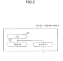
- FIG. 2A block diagram illustrating hardware configurations of the respective main devices.
- a system includes a master main device 101, a first slave main device 102-1, a second slave main device 102-2, and SIP terminals 104-1 to 104-9.
- the number of the master main device 101 is 1, and the number of the second slave main devices is 2 in the example of FIG. 1 , but may be any number other than two.
- the master main device 101, the first slave main device 102-1, and the second slave main device 102-2 are connected to each other via an SIP link 103.
- the SIP link 103 passes communication messages between the main devices.
- the master main device 101 is connected with two SIP terminals 104-4 and 104-5 on TCP/IP.
- the first slave main device 102-1 is connected with three SIP terminals 104-1 to 104-3 on TCP/IP.
- the second slave main device 102-2 is connected with four SIP terminals 104-6 to 104-9.
- the number of the SIP terminals to be connected to each of the main devices is arbitrary.
- the master main device 101 includes a CAPS/OPMS 201, an IOCS 203, multilink sections 205-1 to 205-3, and an SIP terminal connecting section 207.
- the number "3" of the multilink sections 205 corresponds to the number "3" of the main devices. Therefore, when the slave main device is newly added to the system, the multilink section 2-5 is added correspondingly.
- a CAPS of the CAPS/OPMS 201 is a call control module, and an OPMS of the CAPS/OPMS 201 is a package and terminal management module.
- the package refers to, e.g., the SIP terminal connecting section 207.
- the IOCS is an input/output control module.
- the number of the multilink sections 205 is the same as the number of the main devices included in the system. Then the multilink sections 205 each link the IOCS 203 and one SIP terminal connecting section 207 through the SIP link 103.
- the SIP terminal connecting section 207 includes a transmission-side processing section 209, a reception-side processing section 211, and a TCP/IP section 213.
- the transmission-side processing section 209 generates an SIP message composed of texts based on binary data transmitted from the multilink section 205 and transmits the SIP message to the TCP/IP section 213.
- the reception-side processing section 211 analyzes the SIP message received from the TCP/IP section 213 and transmits a result of the analysis to the multilink section 205 in a form of a text message.
- the TCP/IP section 213 passes the SIP message between the transmission-side processing section 209 and SIP terminals 104 and between the reception-side processing section 211 and SIP terminals 104.
- the CAPS/OPMS 201, the IOCS 203, and the multilink sections 205-1 to 205-3 are realized by a CPU 301 of the master main device 101 executing a program for allowing the CPU of the master main device 101 to function as the above sections.
- This program is stored in a memory 302 of the master main device 101.
- the SIP terminal connecting section 207 of the master main device 101 is realized by the CPU 301 of the master main device 101 executing a program for allowing the CPU 301 of the master main device 101 to function as the SIP terminal connecting section 207. This program is also stored in the memory 302 of the master main device 101.
- the SIP terminal connecting section 207 of the first slave main device 102-1 is realized by the CPU 301 of the second slave main device 102-1 executing a program for allowing the CPU 301 of the first slave main device 102-1 to function as the SIP terminal connecting section 207.
- This program is stored in a memory 302 of the first slave main device 102-1.
- the SIP terminal connecting section 207 of the second slave main device 102-2 is realized by the CPU 301 of the second slave main device 102-1 executing a program for allowing the CPU 301 of the second slave main device 102-2 to function as the SIP terminal connecting section 207.
- This program is stored in a memory 302 of the second slave main device 102-2.
- the CAPS/OPMS 201 and IOCS 203 are also generated in the first slave main device 102-1. While the master main device 101 normally operates, the CAPS/OPMS 201 and IOCS 203 of the first slave main device 102-1 is in a standby state; on the other hand, when the master main device 101 has gone down, the CAPS/OPMS 201 and IOCS 203 of the first slave main device 102-1 enters an operating state. At this time, the multilink section 205 is also generated in the first slave main device 102-1.
- the second slave main device has the same as configuration of the first slave main device.
- the present invention can be utilized for allowing one or more SIP terminals to be connected to a system including a plurality of main devices.
Landscapes
- Engineering & Computer Science (AREA)
- Business, Economics & Management (AREA)
- General Business, Economics & Management (AREA)
- Multimedia (AREA)
- Computer Networks & Wireless Communication (AREA)
- Signal Processing (AREA)
- Telephonic Communication Services (AREA)
- Data Exchanges In Wide-Area Networks (AREA)
Abstract
Description
- The present invention relates to an SIP terminal control system and an SIP terminal control method in a system including a master main device and one or more slave main devices.
- In an invention disclosed in
PTL 1, a physical package included in a slave main device is used as a package for controlling a digital terminal and a digital line. The physical package included in the slave main device uses a correspondence table to be associated with a virtual slot included in a master main device. Then the master main device utilizes the association to thereby control the digital terminal and digital line which are connected with the physical package of the slave main device. The physical package included in each slave main device uses a CPU of the corresponding slave main device to control the digital terminal and the like, so that processing for such control can be avoided from being concentrated on a CPU of the master main device. - {PTL 1}
JP-A-2009-003923 - By the way, SIP terminals can be also connected to the system including the master main device and one or more slave main devices. As such, versatility and availability of this system can be enhanced significantly.
- However, each of the SIP terminals may not be connected with the physical package of the slave main device. The master main device directly controls the SIP terminals, so that processing for controlling the SIP terminals are concentrated on the CPU of the master main device. Further, in order to control the individual SIP terminals, heavy load processing such as message processing is required. Thus, the number of the SIP terminals that can be connected to the system including the master main device and one or more slave main devices is considerably restricted.
- An object of the present invention is therefore to provide an SIP terminal control system and an SIP terminal control method that make it possible for multiple SIP terminals to be connected to a system including a master main device and one or more slave main devices. {Solution to Problem}
- According to a first aspect of the present invention, there is provided an SIP terminal control system for a system including a master main device and one or more slave main devices connected to the master main device. The master main device includes a plurality of multilink sections each corresponding to the master main device or to each of the slave main devices, the master main device and the slave main devices each include an SIP terminal connecting section which connects one or more SIP terminals, the multilink sections and the SIP terminal connecting sections are connected to each other by an SIP link, the multilink sections operate by using a CPU of the master main device, and the SIP connecting each operate by using a CPU of the slave main device or master main device that contains the SIP connecting.
According to a second aspect of the present invention, there is provided an SIP terminal control method for a system including a master main device and one or more slave main devices connected to the master main device, the method comprising: generating, in the master main device, a plurality of multilink sections each corresponding to the master main device or to each of the slave main devices; generating, in the master main device and each of the slave main devices, an SIP terminal connecting section which connects one or more SIP terminals; connecting the multilink sections and the SIP terminal connecting sections each other by an SIP link; making the multilink sections operate by using a CPU of the master main device; and making the SIP connecting sections each operate by using a CPU of the slave main device or master main device that contains the SIP connecting section. - According to the present invention, control for the SIP terminal can be distributed to a plurality of main devices to reduce a CPU load of each main device, making it possible for multiple SIP terminals to be connected to a system including a master main device and one or more slave main devices.
-
FIG 1A block diagram illustrating a configuration of a system including an SIP terminal control system according to an exemplary embodiment of the present invention and including a master main device and one or more slave main devices.FIG. 2A block diagram illustrating hardware configurations of the respective main devices. - An exemplary embodiment for exploiting the present invention will be described in detail below with reference to the accompanying drawings.
- As illustrated in
FIG. 1 , a system according to the exemplary embodiment of the present invention includes a mastermain device 101, a first slave main device 102-1, a second slave main device 102-2, and SIP terminals 104-1 to 104-9. - The number of the master
main device 101 is 1, and the number of the second slave main devices is 2 in the example ofFIG. 1 , but may be any number other than two. - The master
main device 101, the first slave main device 102-1, and the second slave main device 102-2 are connected to each other via anSIP link 103. TheSIP link 103 passes communication messages between the main devices. - In the example of
FIG. 1 , the mastermain device 101 is connected with two SIP terminals 104-4 and 104-5 on TCP/IP. The first slave main device 102-1 is connected with three SIP terminals 104-1 to 104-3 on TCP/IP. The second slave main device 102-2 is connected with four SIP terminals 104-6 to 104-9. The number of the SIP terminals to be connected to each of the main devices is arbitrary. - The master
main device 101 includes a CAPS/OPMS 201, anIOCS 203, multilink sections 205-1 to 205-3, and an SIPterminal connecting section 207. The number "3" of the multilink sections 205 corresponds to the number "3" of the main devices. Therefore, when the slave main device is newly added to the system, the multilink section 2-5 is added correspondingly. - A CAPS of the CAPS/OPMS 201 is a call control module, and an OPMS of the CAPS/OPMS 201 is a package and terminal management module. The package refers to, e.g., the SIP
terminal connecting section 207. The IOCS is an input/output control module. - As described above, the number of the multilink sections 205 is the same as the number of the main devices included in the system. Then the multilink sections 205 each link the
IOCS 203 and one SIPterminal connecting section 207 through theSIP link 103. - The SIP
terminal connecting section 207 includes a transmission-side processing section 209, a reception-side processing section 211, and a TCP/IP section 213. - The transmission-
side processing section 209 generates an SIP message composed of texts based on binary data transmitted from the multilink section 205 and transmits the SIP message to the TCP/IP section 213. - The reception-
side processing section 211 analyzes the SIP message received from the TCP/IP section 213 and transmits a result of the analysis to the multilink section 205 in a form of a text message. - The TCP/
IP section 213 passes the SIP message between the transmission-side processing section 209 and SIP terminals 104 and between the reception-side processing section 211 and SIP terminals 104. - The CAPS/
OPMS 201, theIOCS 203, and the multilink sections 205-1 to 205-3 are realized by aCPU 301 of the mastermain device 101 executing a program for allowing the CPU of the mastermain device 101 to function as the above sections. This program is stored in amemory 302 of the mastermain device 101. - The SIP
terminal connecting section 207 of the mastermain device 101 is realized by theCPU 301 of the mastermain device 101 executing a program for allowing theCPU 301 of the mastermain device 101 to function as the SIPterminal connecting section 207. This program is also stored in thememory 302 of the mastermain device 101. - The SIP
terminal connecting section 207 of the first slave main device 102-1 is realized by theCPU 301 of the second slave main device 102-1 executing a program for allowing theCPU 301 of the first slave main device 102-1 to function as the SIPterminal connecting section 207. This program is stored in amemory 302 of the first slave main device 102-1. - The SIP
terminal connecting section 207 of the second slave main device 102-2 is realized by theCPU 301 of the second slave main device 102-1 executing a program for allowing theCPU 301 of the second slave main device 102-2 to function as the SIPterminal connecting section 207. This program is stored in amemory 302 of the second slave main device 102-2. - The above sections are each obtained by instantiating classes in the program within the
memory 302. - The CAPS/OPMS 201 and IOCS 203 are also generated in the first slave main device 102-1. While the master
main device 101 normally operates, the CAPS/OPMS 201 and IOCS 203 of the first slave main device 102-1 is in a standby state; on the other hand, when the mastermain device 101 has gone down, the CAPS/OPMS 201 and IOCS 203 of the first slave main device 102-1 enters an operating state. At this time, the multilink section 205 is also generated in the first slave main device 102-1. - The second slave main device has the same as configuration of the first slave main device.
- The present invention can be utilized for allowing one or more SIP terminals to be connected to a system including a plurality of main devices.
-
- 101:
- Master main device
- 102-1:
- First slave device
- 102-2:
- Second slave device
- 103:
- SIP link
- 104-1 to 104-9:
- SIP terminal
- 201:
- CAPS/OPMS
- 203:
- IOCS
- 205-1, 205-2, 205-3:
- Multilink section
- 207: SIP
- terminal connecting section
- 209:
- Transmission-side processing section
- 211:
- Reception-side processing section
- 213:
- TCP/IP section
Claims (6)
- An SIP terminal control system in a system comprising a master main device and one or more slave main devices connected to the master main device, wherein:the master main device includes a plurality of multilink sections each corresponding to the master main device or to each of the slave main devices,the master main device and the slave main devices each include an SIP terminal connecting section which connects one or more SIP terminals,the multilink sections and the SIP terminal connecting sections are connected to each other by an SIP link,the multilink sections operate by using a CPU of the master main device, andthe SIP connecting sections each operate by using a CPU of the slave main device or master main device that contains the SIP connecting section.
- The SIP terminal control system according to claim 1, wherein
the SIP terminal connecting sections each include at least a transmission-side processing section and a reception-side processing section, and
the transmission-side processing section generates an SIP message composed of texts based on binary data transmitted from the corresponding multilink section. - The SIP terminal control system according to claim 2, wherein
the reception-side processing section analyzes the received text-based SIP message and transmits a result of the analysis to the multilink section. - An SIP terminal control method for a system including a master main device and one or more slave main devices connected to the master main device, the method comprising:generating, in the master main device, a plurality of multilink sections each corresponding to the master main device or to each of the slave main devices;generating, in the master main device and each of the slave main devices, an SIP terminal connecting section which connects one or more SIP terminals;connecting the multilink sections and the SIP terminal connecting sections each other by an SIP link;causing the multilink sections to operate by using a CPU of the master main device; andcausing the SIP connecting sections each to operate by using a CPU of the slave main device or master main device that contains the SIP connecting section.
- A program for allowing a computer to function as the multilink sections as claimed in Claim 1.
- A program for allowing a computer to function as the SIP terminal connecting sections as claimed in any one of claims 1 to 3.
Applications Claiming Priority (2)
| Application Number | Priority Date | Filing Date | Title |
|---|---|---|---|
| JP2010020200A JP5057121B2 (en) | 2010-02-01 | 2010-02-01 | SIP terminal control system and SIP terminal control method |
| PCT/JP2011/050811 WO2011093178A1 (en) | 2010-02-01 | 2011-01-19 | Sip terminal control system and sip terminal control method |
Publications (3)
| Publication Number | Publication Date |
|---|---|
| EP2533508A1 true EP2533508A1 (en) | 2012-12-12 |
| EP2533508A4 EP2533508A4 (en) | 2017-04-12 |
| EP2533508B1 EP2533508B1 (en) | 2018-08-15 |
Family
ID=44319169
Family Applications (1)
| Application Number | Title | Priority Date | Filing Date |
|---|---|---|---|
| EP11736892.8A Active EP2533508B1 (en) | 2010-02-01 | 2011-01-19 | Sip terminal control system and sip terminal control method |
Country Status (7)
| Country | Link |
|---|---|
| US (1) | US9154525B2 (en) |
| EP (1) | EP2533508B1 (en) |
| JP (1) | JP5057121B2 (en) |
| CN (1) | CN102714677B (en) |
| AU (1) | AU2011210960B2 (en) |
| CA (1) | CA2788619C (en) |
| WO (1) | WO2011093178A1 (en) |
Families Citing this family (1)
| Publication number | Priority date | Publication date | Assignee | Title |
|---|---|---|---|---|
| WO2015042566A1 (en) * | 2013-09-23 | 2015-03-26 | Clearsign Combustion Corporation | Control of combustion reaction physical extent |
Family Cites Families (14)
| Publication number | Priority date | Publication date | Assignee | Title |
|---|---|---|---|---|
| JP2654027B2 (en) | 1987-09-04 | 1997-09-17 | 株式会社東芝 | Digital key telephone equipment |
| JP3335686B2 (en) * | 1992-03-19 | 2002-10-21 | 日本電気通信システム株式会社 | Multi-link control method |
| KR960013971B1 (en) * | 1993-12-03 | 1996-10-10 | 현대전자산업 주식회사 | Attendant console interface device and its operation method of medium capacity private exchange |
| JP2000165431A (en) | 1998-11-24 | 2000-06-16 | Matsushita Electric Ind Co Ltd | Network system setting method |
| US7535915B2 (en) * | 2001-12-31 | 2009-05-19 | Samsung Electronics Co., Ltd. | System and method for scalable and redundant SIP message routing in an IP multimedia subsystem |
| JP3963164B2 (en) * | 2003-08-29 | 2007-08-22 | サクサ株式会社 | Telephone system |
| JP2007088894A (en) * | 2005-09-22 | 2007-04-05 | Toshiba Corp | Telephone system |
| JP2007134967A (en) * | 2005-11-10 | 2007-05-31 | Oki Electric Ind Co Ltd | Communication system, communication method, communication program, call processor, and telephone terminal |
| JP4796945B2 (en) * | 2006-11-22 | 2011-10-19 | Necインフロンティア株式会社 | Telephone exchange system |
| CA2630014C (en) | 2007-05-18 | 2014-05-27 | Nec Infrontia Corporation | Main device redundancy configuration and main device replacing method |
| US8244949B2 (en) | 2007-05-18 | 2012-08-14 | Nec Infrontia Corporation | Slot interface access unit, method thereof, and program thereof, as well as redundancy configuration of main unit, and replacing method of the same |
| JP5366177B2 (en) * | 2007-05-18 | 2013-12-11 | Necインフロンティア株式会社 | Slot interface access device, method and program thereof, and redundant configuration and alternative method of main device |
| JP2009033447A (en) * | 2007-07-26 | 2009-02-12 | Toshiba Corp | Interface device, main device, and control method used for interface device |
| JP5177852B2 (en) * | 2008-01-23 | 2013-04-10 | Necインフロンティア株式会社 | License key sharing method and license key sharing system |
-
2010
- 2010-02-01 JP JP2010020200A patent/JP5057121B2/en active Active
-
2011
- 2011-01-19 AU AU2011210960A patent/AU2011210960B2/en active Active
- 2011-01-19 CA CA2788619A patent/CA2788619C/en active Active
- 2011-01-19 EP EP11736892.8A patent/EP2533508B1/en active Active
- 2011-01-19 CN CN201180007997.8A patent/CN102714677B/en active Active
- 2011-01-19 WO PCT/JP2011/050811 patent/WO2011093178A1/en not_active Ceased
- 2011-01-19 US US13/576,111 patent/US9154525B2/en active Active
Non-Patent Citations (1)
| Title |
|---|
| See references of WO2011093178A1 * |
Also Published As
| Publication number | Publication date |
|---|---|
| JP5057121B2 (en) | 2012-10-24 |
| AU2011210960A1 (en) | 2012-08-16 |
| HK1174457A1 (en) | 2013-06-07 |
| AU2011210960B2 (en) | 2014-03-06 |
| US9154525B2 (en) | 2015-10-06 |
| US20130007179A1 (en) | 2013-01-03 |
| CA2788619C (en) | 2017-02-28 |
| EP2533508B1 (en) | 2018-08-15 |
| WO2011093178A1 (en) | 2011-08-04 |
| EP2533508A4 (en) | 2017-04-12 |
| CA2788619A1 (en) | 2011-08-04 |
| CN102714677A (en) | 2012-10-03 |
| JP2011160192A (en) | 2011-08-18 |
| CN102714677B (en) | 2014-10-22 |
Similar Documents
| Publication | Publication Date | Title |
|---|---|---|
| US11240159B2 (en) | Service link selection control method and device | |
| EP3291089A1 (en) | Data processing method and apparatus | |
| US10445952B2 (en) | Motor vehicle having a communication unit for multiple control units | |
| US9928206B2 (en) | Dedicated LAN interface per IPMI instance on a multiple baseboard management controller (BMC) system with single physical network interface | |
| WO2020109867A3 (en) | Multi-mode communication device, method and system | |
| EP2541349A2 (en) | Inverter system having a safety module | |
| EP2330583A3 (en) | System and method for delivery of non-textual controller pilot data link communications (cpdlc) for pilot review | |
| CN104158683A (en) | Cross-device aggregation group rapid convergence method, and cross-device aggregation group rapid convergence device | |
| US20090240859A1 (en) | Automatic address setting system | |
| EP2533508B1 (en) | Sip terminal control system and sip terminal control method | |
| CN110417761A (en) | Communication means and device based on dual-computer redundancy | |
| CN112565041B (en) | Hardware information configuration method, device and medium of FF field bus system | |
| JP5458968B2 (en) | Safety control system | |
| CN103034545B (en) | Communication means between communications framework based on ACE and method and functional module | |
| WO2018177792A1 (en) | Rule-based communicating of equipment data from an industrial system to an analysis system using uni-directional interfaces | |
| HK1174457B (en) | Sip terminal control system and sip terminal control method | |
| CN105550153B (en) | A kind of 1394 bus multi-channel flow datas are unpacked method parallel | |
| CN106354811A (en) | Method, device and system for processing picture output abnormal conditions | |
| CN104506423A (en) | Communication method and communication device | |
| CN110515776B (en) | Dual-computer backup system and backup method | |
| EP2432152B1 (en) | Method and apparatus for switching the main/standby single board | |
| CN202275525U (en) | Electronic reader and system based on the electronic reader | |
| JP5535844B2 (en) | Name resolution apparatus and name resolution method | |
| CN101515855A (en) | Method for realizing integrated charging gateway in on-line charging system | |
| CN117914672A (en) | Message transmission method, device and server |
Legal Events
| Date | Code | Title | Description |
|---|---|---|---|
| PUAI | Public reference made under article 153(3) epc to a published international application that has entered the european phase |
Free format text: ORIGINAL CODE: 0009012 |
|
| 17P | Request for examination filed |
Effective date: 20120823 |
|
| AK | Designated contracting states |
Kind code of ref document: A1 Designated state(s): AL AT BE BG CH CY CZ DE DK EE ES FI FR GB GR HR HU IE IS IT LI LT LU LV MC MK MT NL NO PL PT RO RS SE SI SK SM TR |
|
| DAX | Request for extension of the european patent (deleted) | ||
| RAP1 | Party data changed (applicant data changed or rights of an application transferred) |
Owner name: NEC PLATFORMS, LTD. |
|
| RA4 | Supplementary search report drawn up and despatched (corrected) |
Effective date: 20170315 |
|
| RIC1 | Information provided on ipc code assigned before grant |
Ipc: H04L 29/06 20060101ALI20170309BHEP Ipc: H04M 3/00 20060101AFI20170309BHEP |
|
| GRAP | Despatch of communication of intention to grant a patent |
Free format text: ORIGINAL CODE: EPIDOSNIGR1 |
|
| STAA | Information on the status of an ep patent application or granted ep patent |
Free format text: STATUS: GRANT OF PATENT IS INTENDED |
|
| INTG | Intention to grant announced |
Effective date: 20180308 |
|
| GRAS | Grant fee paid |
Free format text: ORIGINAL CODE: EPIDOSNIGR3 |
|
| GRAA | (expected) grant |
Free format text: ORIGINAL CODE: 0009210 |
|
| STAA | Information on the status of an ep patent application or granted ep patent |
Free format text: STATUS: THE PATENT HAS BEEN GRANTED |
|
| AK | Designated contracting states |
Kind code of ref document: B1 Designated state(s): AL AT BE BG CH CY CZ DE DK EE ES FI FR GB GR HR HU IE IS IT LI LT LU LV MC MK MT NL NO PL PT RO RS SE SI SK SM TR |
|
| REG | Reference to a national code |
Ref country code: CH Ref legal event code: EP Ref country code: GB Ref legal event code: FG4D Ref country code: AT Ref legal event code: REF Ref document number: 1031130 Country of ref document: AT Kind code of ref document: T Effective date: 20180815 |
|
| REG | Reference to a national code |
Ref country code: IE Ref legal event code: FG4D |
|
| REG | Reference to a national code |
Ref country code: DE Ref legal event code: R096 Ref document number: 602011051068 Country of ref document: DE |
|
| REG | Reference to a national code |
Ref country code: NL Ref legal event code: MP Effective date: 20180815 |
|
| REG | Reference to a national code |
Ref country code: LT Ref legal event code: MG4D |
|
| REG | Reference to a national code |
Ref country code: AT Ref legal event code: MK05 Ref document number: 1031130 Country of ref document: AT Kind code of ref document: T Effective date: 20180815 |
|
| PG25 | Lapsed in a contracting state [announced via postgrant information from national office to epo] |
Ref country code: NL Free format text: LAPSE BECAUSE OF FAILURE TO SUBMIT A TRANSLATION OF THE DESCRIPTION OR TO PAY THE FEE WITHIN THE PRESCRIBED TIME-LIMIT Effective date: 20180815 Ref country code: BG Free format text: LAPSE BECAUSE OF FAILURE TO SUBMIT A TRANSLATION OF THE DESCRIPTION OR TO PAY THE FEE WITHIN THE PRESCRIBED TIME-LIMIT Effective date: 20181115 Ref country code: LT Free format text: LAPSE BECAUSE OF FAILURE TO SUBMIT A TRANSLATION OF THE DESCRIPTION OR TO PAY THE FEE WITHIN THE PRESCRIBED TIME-LIMIT Effective date: 20180815 Ref country code: AT Free format text: LAPSE BECAUSE OF FAILURE TO SUBMIT A TRANSLATION OF THE DESCRIPTION OR TO PAY THE FEE WITHIN THE PRESCRIBED TIME-LIMIT Effective date: 20180815 Ref country code: SE Free format text: LAPSE BECAUSE OF FAILURE TO SUBMIT A TRANSLATION OF THE DESCRIPTION OR TO PAY THE FEE WITHIN THE PRESCRIBED TIME-LIMIT Effective date: 20180815 Ref country code: IS Free format text: LAPSE BECAUSE OF FAILURE TO SUBMIT A TRANSLATION OF THE DESCRIPTION OR TO PAY THE FEE WITHIN THE PRESCRIBED TIME-LIMIT Effective date: 20181215 Ref country code: NO Free format text: LAPSE BECAUSE OF FAILURE TO SUBMIT A TRANSLATION OF THE DESCRIPTION OR TO PAY THE FEE WITHIN THE PRESCRIBED TIME-LIMIT Effective date: 20181115 Ref country code: GR Free format text: LAPSE BECAUSE OF FAILURE TO SUBMIT A TRANSLATION OF THE DESCRIPTION OR TO PAY THE FEE WITHIN THE PRESCRIBED TIME-LIMIT Effective date: 20181116 Ref country code: RS Free format text: LAPSE BECAUSE OF FAILURE TO SUBMIT A TRANSLATION OF THE DESCRIPTION OR TO PAY THE FEE WITHIN THE PRESCRIBED TIME-LIMIT Effective date: 20180815 Ref country code: FI Free format text: LAPSE BECAUSE OF FAILURE TO SUBMIT A TRANSLATION OF THE DESCRIPTION OR TO PAY THE FEE WITHIN THE PRESCRIBED TIME-LIMIT Effective date: 20180815 |
|
| PG25 | Lapsed in a contracting state [announced via postgrant information from national office to epo] |
Ref country code: HR Free format text: LAPSE BECAUSE OF FAILURE TO SUBMIT A TRANSLATION OF THE DESCRIPTION OR TO PAY THE FEE WITHIN THE PRESCRIBED TIME-LIMIT Effective date: 20180815 Ref country code: AL Free format text: LAPSE BECAUSE OF FAILURE TO SUBMIT A TRANSLATION OF THE DESCRIPTION OR TO PAY THE FEE WITHIN THE PRESCRIBED TIME-LIMIT Effective date: 20180815 Ref country code: LV Free format text: LAPSE BECAUSE OF FAILURE TO SUBMIT A TRANSLATION OF THE DESCRIPTION OR TO PAY THE FEE WITHIN THE PRESCRIBED TIME-LIMIT Effective date: 20180815 |
|
| PG25 | Lapsed in a contracting state [announced via postgrant information from national office to epo] |
Ref country code: PL Free format text: LAPSE BECAUSE OF FAILURE TO SUBMIT A TRANSLATION OF THE DESCRIPTION OR TO PAY THE FEE WITHIN THE PRESCRIBED TIME-LIMIT Effective date: 20180815 Ref country code: EE Free format text: LAPSE BECAUSE OF FAILURE TO SUBMIT A TRANSLATION OF THE DESCRIPTION OR TO PAY THE FEE WITHIN THE PRESCRIBED TIME-LIMIT Effective date: 20180815 Ref country code: IT Free format text: LAPSE BECAUSE OF FAILURE TO SUBMIT A TRANSLATION OF THE DESCRIPTION OR TO PAY THE FEE WITHIN THE PRESCRIBED TIME-LIMIT Effective date: 20180815 Ref country code: CZ Free format text: LAPSE BECAUSE OF FAILURE TO SUBMIT A TRANSLATION OF THE DESCRIPTION OR TO PAY THE FEE WITHIN THE PRESCRIBED TIME-LIMIT Effective date: 20180815 Ref country code: RO Free format text: LAPSE BECAUSE OF FAILURE TO SUBMIT A TRANSLATION OF THE DESCRIPTION OR TO PAY THE FEE WITHIN THE PRESCRIBED TIME-LIMIT Effective date: 20180815 Ref country code: ES Free format text: LAPSE BECAUSE OF FAILURE TO SUBMIT A TRANSLATION OF THE DESCRIPTION OR TO PAY THE FEE WITHIN THE PRESCRIBED TIME-LIMIT Effective date: 20180815 |
|
| REG | Reference to a national code |
Ref country code: DE Ref legal event code: R097 Ref document number: 602011051068 Country of ref document: DE |
|
| PG25 | Lapsed in a contracting state [announced via postgrant information from national office to epo] |
Ref country code: SK Free format text: LAPSE BECAUSE OF FAILURE TO SUBMIT A TRANSLATION OF THE DESCRIPTION OR TO PAY THE FEE WITHIN THE PRESCRIBED TIME-LIMIT Effective date: 20180815 Ref country code: SM Free format text: LAPSE BECAUSE OF FAILURE TO SUBMIT A TRANSLATION OF THE DESCRIPTION OR TO PAY THE FEE WITHIN THE PRESCRIBED TIME-LIMIT Effective date: 20180815 Ref country code: DK Free format text: LAPSE BECAUSE OF FAILURE TO SUBMIT A TRANSLATION OF THE DESCRIPTION OR TO PAY THE FEE WITHIN THE PRESCRIBED TIME-LIMIT Effective date: 20180815 |
|
| PLBE | No opposition filed within time limit |
Free format text: ORIGINAL CODE: 0009261 |
|
| STAA | Information on the status of an ep patent application or granted ep patent |
Free format text: STATUS: NO OPPOSITION FILED WITHIN TIME LIMIT |
|
| 26N | No opposition filed |
Effective date: 20190516 |
|
| PG25 | Lapsed in a contracting state [announced via postgrant information from national office to epo] |
Ref country code: MC Free format text: LAPSE BECAUSE OF FAILURE TO SUBMIT A TRANSLATION OF THE DESCRIPTION OR TO PAY THE FEE WITHIN THE PRESCRIBED TIME-LIMIT Effective date: 20180815 Ref country code: SI Free format text: LAPSE BECAUSE OF FAILURE TO SUBMIT A TRANSLATION OF THE DESCRIPTION OR TO PAY THE FEE WITHIN THE PRESCRIBED TIME-LIMIT Effective date: 20180815 |
|
| REG | Reference to a national code |
Ref country code: CH Ref legal event code: PL |
|
| PG25 | Lapsed in a contracting state [announced via postgrant information from national office to epo] |
Ref country code: LU Free format text: LAPSE BECAUSE OF NON-PAYMENT OF DUE FEES Effective date: 20190119 |
|
| REG | Reference to a national code |
Ref country code: BE Ref legal event code: MM Effective date: 20190131 |
|
| REG | Reference to a national code |
Ref country code: IE Ref legal event code: MM4A |
|
| PG25 | Lapsed in a contracting state [announced via postgrant information from national office to epo] |
Ref country code: BE Free format text: LAPSE BECAUSE OF NON-PAYMENT OF DUE FEES Effective date: 20190131 |
|
| PG25 | Lapsed in a contracting state [announced via postgrant information from national office to epo] |
Ref country code: CH Free format text: LAPSE BECAUSE OF NON-PAYMENT OF DUE FEES Effective date: 20190131 Ref country code: LI Free format text: LAPSE BECAUSE OF NON-PAYMENT OF DUE FEES Effective date: 20190131 |
|
| PG25 | Lapsed in a contracting state [announced via postgrant information from national office to epo] |
Ref country code: IE Free format text: LAPSE BECAUSE OF NON-PAYMENT OF DUE FEES Effective date: 20190119 |
|
| PG25 | Lapsed in a contracting state [announced via postgrant information from national office to epo] |
Ref country code: TR Free format text: LAPSE BECAUSE OF FAILURE TO SUBMIT A TRANSLATION OF THE DESCRIPTION OR TO PAY THE FEE WITHIN THE PRESCRIBED TIME-LIMIT Effective date: 20180815 |
|
| PG25 | Lapsed in a contracting state [announced via postgrant information from national office to epo] |
Ref country code: MT Free format text: LAPSE BECAUSE OF NON-PAYMENT OF DUE FEES Effective date: 20190119 Ref country code: PT Free format text: LAPSE BECAUSE OF FAILURE TO SUBMIT A TRANSLATION OF THE DESCRIPTION OR TO PAY THE FEE WITHIN THE PRESCRIBED TIME-LIMIT Effective date: 20181215 |
|
| PG25 | Lapsed in a contracting state [announced via postgrant information from national office to epo] |
Ref country code: CY Free format text: LAPSE BECAUSE OF FAILURE TO SUBMIT A TRANSLATION OF THE DESCRIPTION OR TO PAY THE FEE WITHIN THE PRESCRIBED TIME-LIMIT Effective date: 20180815 |
|
| PG25 | Lapsed in a contracting state [announced via postgrant information from national office to epo] |
Ref country code: HU Free format text: LAPSE BECAUSE OF FAILURE TO SUBMIT A TRANSLATION OF THE DESCRIPTION OR TO PAY THE FEE WITHIN THE PRESCRIBED TIME-LIMIT; INVALID AB INITIO Effective date: 20110119 |
|
| PG25 | Lapsed in a contracting state [announced via postgrant information from national office to epo] |
Ref country code: MK Free format text: LAPSE BECAUSE OF FAILURE TO SUBMIT A TRANSLATION OF THE DESCRIPTION OR TO PAY THE FEE WITHIN THE PRESCRIBED TIME-LIMIT Effective date: 20180815 |
|
| PGFP | Annual fee paid to national office [announced via postgrant information from national office to epo] |
Ref country code: GB Payment date: 20260123 Year of fee payment: 16 |
|
| PGFP | Annual fee paid to national office [announced via postgrant information from national office to epo] |
Ref country code: DE Payment date: 20260121 Year of fee payment: 16 |
|
| PGFP | Annual fee paid to national office [announced via postgrant information from national office to epo] |
Ref country code: FR Payment date: 20260123 Year of fee payment: 16 |