EP2533378A1 - Method of manufacturing terminal with press-fit engaging section - Google Patents
Method of manufacturing terminal with press-fit engaging section Download PDFInfo
- Publication number
- EP2533378A1 EP2533378A1 EP11739846A EP11739846A EP2533378A1 EP 2533378 A1 EP2533378 A1 EP 2533378A1 EP 11739846 A EP11739846 A EP 11739846A EP 11739846 A EP11739846 A EP 11739846A EP 2533378 A1 EP2533378 A1 EP 2533378A1
- Authority
- EP
- European Patent Office
- Prior art keywords
- terminals
- press
- parts
- fit engaging
- engaging parts
- Prior art date
- Legal status (The legal status is an assumption and is not a legal conclusion. Google has not performed a legal analysis and makes no representation as to the accuracy of the status listed.)
- Withdrawn
Links
Images




Classifications
-
- H—ELECTRICITY
- H01—ELECTRIC ELEMENTS
- H01R—ELECTRICALLY-CONDUCTIVE CONNECTIONS; STRUCTURAL ASSOCIATIONS OF A PLURALITY OF MUTUALLY-INSULATED ELECTRICAL CONNECTING ELEMENTS; COUPLING DEVICES; CURRENT COLLECTORS
- H01R43/00—Apparatus or processes specially adapted for manufacturing, assembling, maintaining, or repairing of line connectors or current collectors or for joining electric conductors
- H01R43/16—Apparatus or processes specially adapted for manufacturing, assembling, maintaining, or repairing of line connectors or current collectors or for joining electric conductors for manufacturing contact members, e.g. by punching and by bending
-
- H—ELECTRICITY
- H01—ELECTRIC ELEMENTS
- H01R—ELECTRICALLY-CONDUCTIVE CONNECTIONS; STRUCTURAL ASSOCIATIONS OF A PLURALITY OF MUTUALLY-INSULATED ELECTRICAL CONNECTING ELEMENTS; COUPLING DEVICES; CURRENT COLLECTORS
- H01R13/00—Details of coupling devices of the kinds covered by groups H01R12/70 or H01R24/00 - H01R33/00
- H01R13/40—Securing contact members in or to a base or case; Insulating of contact members
- H01R13/405—Securing in non-demountable manner, e.g. moulding, riveting
- H01R13/41—Securing in non-demountable manner, e.g. moulding, riveting by frictional grip in grommet, panel or base
-
- H—ELECTRICITY
- H01—ELECTRIC ELEMENTS
- H01R—ELECTRICALLY-CONDUCTIVE CONNECTIONS; STRUCTURAL ASSOCIATIONS OF A PLURALITY OF MUTUALLY-INSULATED ELECTRICAL CONNECTING ELEMENTS; COUPLING DEVICES; CURRENT COLLECTORS
- H01R43/00—Apparatus or processes specially adapted for manufacturing, assembling, maintaining, or repairing of line connectors or current collectors or for joining electric conductors
- H01R43/20—Apparatus or processes specially adapted for manufacturing, assembling, maintaining, or repairing of line connectors or current collectors or for joining electric conductors for assembling or disassembling contact members with insulating base, case or sleeve
Definitions
- the invention is related to a method for manufacturing terminals which have press-fit engaging parts that prevent the terminals from being pulling out when the terminals are press-fitted into press-fitting holes of a connector housing.
- the press-fit engaging parts are not formed at the time of press punching in the first step, it is possible in this stage to mold the terminals with narrow pitches by making the clearance small.
- the crushing pressures are only applied to the prescribed parts of the terminals, a special clearance is unnecessary and the press-fit engaging parts of a shape which has a sufficient projection margin can be simply formed. Therefore, it becomes possible to narrow the pitch of the terminals having the press-fit engaging parts which can secure a required holding force.
Landscapes
- Engineering & Computer Science (AREA)
- Manufacturing & Machinery (AREA)
- Manufacturing Of Electrical Connectors (AREA)
- Connector Housings Or Holding Contact Members (AREA)
Abstract
A method for manufacturing terminals is provided which can form press-fit engaging parts that can secure a necessary holding force without being affected by a clearance between terminals.
The method for manufacturing terminals includes a first step in which a plurality of terminals (20) arranged in parallel to each other at a prescribed interval laterally in a row, while connected to a carrier (11), are collectively molded by press punching a sheet metal, and a second step after the first step in which press-fit engaging parts (22), which prevent the terminals from being pulling out when the terminals are press-fitted into press-fitting holes of a connector housing, are formed by applying a crushing pressure in a vertical direction that is perpendicular to the direction of arranging the terminals, onto prescribed parts in the longitudinal direction of the terminals, and making parts at the side surfaces of the terminals to be locally and convexly bulged sidewards.
Description
- The invention is related to a method for manufacturing terminals which have press-fit engaging parts that prevent the terminals from being pulling out when the terminals are press-fitted into press-fitting holes of a connector housing.
- A connector for circuit boards is often manufactured, for example, by press-fitting a plurality of terminals into press-fitting holes of a connector housing from back while the plurality of terminals are connected to a carrier, and cutting the carrier after the press-fitting. It is common that the plurality of terminals used in this kind of connector are molded collectively for each carrier by press punching one piece of sheet metal.
-
Fig. 14 shows a molded article of a group of such molded terminals (for example, refer to a PTL 1). In the molded article, a plurality ofterminals 210 are arranged in parallel to each other at a prescribed interval lateral in a row, and each of the base ends of theterminals 210 is connected to acarrier 200. Each of theterminal 210 has anelectrical contact part 211, which electrically contacts with a mating connector terminal, at the front of theterminal 210, a press-fit engaging part 212 behind theelectrical contact part 211, and ahind leg 213, which extends from the rear of a connector housing when theterminal 210 is installed into the connector housing, behind the press-fit engaging part 212. The press-fit engaging part 212 includes punchedparts terminal 210 to become locally convex at the time of press punching. - [PTL 1]
JP-A-2004-63101 - Recently, a demand of making the pitch between terminals as narrow as possible has become strong due to the downsizing of the connector. However, when the
terminals 210 are collectively molded by press punching while theterminals 210 are connected with thecarrier 200 as mentioned above, it is required to secure a clearance betweenadjacent terminals 210. But when the pitch betweenterminals 210 becomes narrow, it becomes impossible to fabricate the press-fitengaging parts 212 that have a sufficient form to be projected towards the clearance side. That is, it is impossible to fabricate the press-fit engaging parts with a sufficient projection margin to secure a holding force required at the time of press-fitting. Therefore, there is a problem that the shortening of the terminal pitch is restricted by the width of the press-fitengaging parts 212. - In view of the above situation, the invention is intended to provide a method for manufacturing terminals which can form press-fit engaging parts that can secure a necessary holding force without being affected by a clearance between terminals.
- In order to solve the above technical problem, according to a first invention, there is provided a method for manufacturing terminals which have press-fit engaging parts, comprising:
- a first step for collectively forming a plurality of terminals arranged in parallel to each other at an interval laterally in a row in a state connected to a carrier, by press punching a sheet metal; and
- a second step for forming the press-fit engaging parts after the first step, by applying crushing pressure in a vertical direction that is perpendicular to an arranging direction of the terminals and a longitudinal direction of the terminals, onto prescribed parts in the longitudinal direction of the terminals so as to make a part of a side surface of each of the terminals to be locally and convexly bulged in at least one direction of side direction and up and down direction, wherein the press-fit engaging parts prevent the terminals from being pulling out when the terminals are press-fitted into press-fitting holes of a connector housing.
- According to a second invention, there is provided the method for manufacturing the terminals which have the press-fit engaging parts according to the first invention, wherein
two convex bulged parts are formed in a row in the longitudinal direction of the terminals as the press-fit engaging parts, and
the first bulged part is formed by applying a crushing pressure from upward and the second bulged part is formed by applying a crushing pressure from downward. - According to a third invention, there is provided the method for manufacturing the terminals which have the press-fit engaging parts according to the first invention, wherein
the convex bulged parts as the press-fit engaging parts are formed by simultaneously applying crushing pressure on same parts from both upward and downward. - According to the first invention, since the press-fit engaging parts are not formed at the time of press punching in the first step, it is possible in this stage to mold the terminals with narrow pitches by making the clearance small. In the following second step, since the crushing pressures are only applied to the prescribed parts of the terminals, a special clearance is unnecessary and the press-fit engaging parts of a shape which has a sufficient projection margin can be simply formed. Therefore, it becomes possible to narrow the pitch of the terminals having the press-fit engaging parts which can secure a required holding force.
- According to the second invention, since the crushing pressures are applied from top and bottom, respectively, it is possible to manufacture while balance is further maintained.
- According to the third invention, since the crushing pressures are applied from top and bottom on the same parts, the press-fit engaging parts can be easily made by deforming the material.
-
-
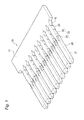
Fig. 1 is a perspective view which shows a complete state of a molded article that contains terminals manufactured with the method of a first embodiment of the invention. -
Fig. 2 is a top view which shows a state after a first step is performed when the terminals are manufactured. -
Fig. 3 is a top view which shows a state after a second step is performed following the first step. -
Fig. 4 is a perspective view which shows the structure of one of the terminals. -
Fig. 5 is a top view which shows the structure of one of the terminals. -
Fig. 6 is a side view which shows the structure of one of the terminals. -
Fig. 7 is a sectional view which is seen from top and shows that the terminals are going to be collectively press-fitted into a connector housing while the terminals are connected with a carrier. -
Fig. 8 is a sectional view which is seen from top and shows that a connector is completed by cutting out the carrier after the terminals ofFig. 7 are press-fitted. -
Fig. 9 is a figure which shows the structure of one of the terminals manufactured with the method of a second embodiment of the invention, in whichFig. 9(a) is a top view,Fig. 9(b) is a side view andFig. 9(c) is an enlarged figure of an area C ofFig. 9(b) . -
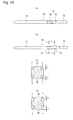
Fig. 10 is a figure which shows the structure of one of the terminals manufactured with the method of a third embodiment of the invention, in whichFig. 10(a) is a top view,Fig. 10(b) is a side view,Fig. 10(c) is a sectional view taken along the line indicated by C-C arrows ofFig. 10(b), and Fig. 10(d) is a sectional view taken along the line indicated by D-D arrows ofFig. 10(b) . -
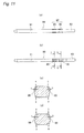
Fig. 11 is a figure which shows the structure of one of the terminals manufactured with the method of a fourth embodiment of the invention, in whichFig. 11 (a) is a top view,Fig. 11 (b) is a side view,Fig. 11 (c) is a sectional view taken along the line indicated by C-C arrows ofFig. 11 (b), and Fig. 11 (d) is a sectional view taken along the line indicated by D-D arrows ofFig. 11(b) . -
Fig. 12 is a figure which shows the structure of one of the terminals manufactured with the method of a fifth embodiment of the invention, in whichFig. 12(a) is a top view,Fig. 12(b) is a side view,Fig. 12(c) is a sectional view taken along the line indicated by C-C arrows ofFig. 12(b), and Fig. 12(d) is a sectional view taken along the line indicated by D-D arrows ofFig. 12(b) . -
Fig. 13 is a figure which shows the structure of one of the terminals manufactured with the method of a sixth embodiment of the invention, in whichFig. 13(a) is a top view,Fig. 13(b) is a side view,Fig. 13(c) is a sectional view taken along the line indicated by C-C arrows ofFig. 13(b), and Fig. 13(d) is a sectional view taken along the line indicated by D-D arrows ofFig. 13(b) . -
Fig. 14 is an explanatory view of a conventional terminal manufacturing method. - Below, the embodiments of the invention are described with reference to the figures.
-
Fig. 1 is a perspective view which shows a complete state of a molded article that contains terminals manufactured with the method of a first embodiment of the invention,Fig. 2 is a top view which shows a state after a first step is performed when the terminals are manufactured,Fig. 3 is a top view which shows a state after a second step is performed following the first step,Fig. 4 is a perspective view which shows the structure of one of the terminals,Fig. 5 is a top view, andFig 6 is a side view.Fig. 7 is a sectional view which is seen from top and shows that the terminals are going to be collectively press-fitted into a connector housing while the terminals are connected with a carrier, andFig. 8 is a sectional view which is seen from top and shows that a connector is completed by cutting out the carrier after the terminals ofFig. 7 are press-fitted. - A molded
article 10 which contains a plurality of pin-shaped terminals 20 whose base ends are connected with acarrier 11 is obtained, as finally shown inFig. 1 , with the manufacturing method of the first embodiment. Each of theterminals 20 has anelectrical contact part 21, which electrically contacts with a mating connector terminal, at the front, a press-fit engaging part 22, which has a fixing function that prevents the terminal from being pulling out when the terminal is press-fitted into a press-fitting hole of a connector housing, behind theelectrical contact part 21, and ahind leg 23 for connecting with a wiring part such as a circuit board behind the press-fit engaging part 22. - When the molded
article 10 which contains the plurality ofterminals 20 is to be obtained, in an initial first step, first, as shown inFig. 2 , while a plurality ofterminals 20 arranged in parallel to each other at a prescribed interval laterally in a row are connected to acarrier 11, themolded article 10 is collectively molded by press punching a sheet metal. - Next, as shown in
Figs. 3 to 6 , in a second step, the press-fit engagingparts 22, which prevent theterminals 20 from being pulling out when theterminals 20 are press-fitted into the press-fitting holes of the connector housing, are formed by applying crushing pressures A and B in vertical directions (up and down directions inFig. 6 ) that are perpendicular to the direction of arranging theterminals 20 and the longitudinal direction of theterminals 20, onto prescribed parts in the longitudinal direction of theterminals 20, to make the applied points dented and parts at the side surfaces of the terminals to be locally and convexly bulged and deformed sidewards. - In this case, two convex bulged
parts terminals 20 as the press-fit engagingparts 22, in which, as shown inFig. 6 , the first bulgedpart 25 is formed when a crushing pressure A is applied by apressing mold 35 from top and the second bulgedpart 26 is formed when a crushing pressure B is applied by apressing mold 36 from bottom. In this case, the front ends 25a and 26a of the parts which can be dented are crushed lightly, and theback ends Figs. 4 and5 , since the side surfaces of theterminal 20 are largely bulged sidewards as the parts are crushed strongly, the shape of the bulgedparts - When the
terminals 20 are manufactured in this way, since the press-fitengaging parts 22 are not formed at the time of press punching in the first step, it is possible in this stage to mold theterminals 20 with narrow pitches by making the clearance between theterminals 20 small. In the following second step, since the crushing pressures A and B are only applied to the prescribed parts of theterminals 20, a special clearance is unnecessary and the press-fitengaging parts 22 of a shape which has a sufficient projection margin S (refer toFig. 5 ) can be simply formed. Therefore, it becomes possible to narrow the pitch of theterminals 20 having the press-fitengaging parts 22 which can secure a required holding force. It is possible to reduce the material by narrowing the pitch of theterminals 20. In this embodiment, when the press-fitengaging parts 22 are made, since the crushing pressures A and B are applied from top and bottom, respectively, it is possible to manufacture while balance is maintained. - When the
terminals 20 molded in this way are assembled to the connector housing, as shown inFig. 7 , theterminals 20 are press-fitted into the press-fittingholes 52 of therear wall 51 of theconnector housing 50, respectively, while theterminals 20 of themolded article 10 are connected with thecarrier 11. Since the press-fit engaging parts 22 whose width is larger than that of the press-fittingholes 52 are pushed into the press-fittingholes 52 and make the hole walls of the press-fittingholes 52 to be transformed, as shown inFig. 8 , theterminals 20 are strongly fixed in therear wall 51 of theconnector housing 50. At this time, theelectrical contact parts 21 are accommodated in ahood 53. Thus, after that, a connector can be completed by cutting out the carrier 11 (refer toFig. 7 ). - The method of forming the press-
fit engaging parts 22 is not limited to the above-mentioned embodiment.Figs. 9(a) to 13(d) show the structures ofterminals -
Figs. 9(a) to 9(c) are figures which show the structure of one of theterminals 60 manufactured with the method of a second embodiment, in whichFig. 9(a) is a top view,Fig. 9(b) is a side view andFig. 9(c) is an enlarged figure of an area C ofFig. 9(b) .Figs. 10(a) to 10(d) are figures which show the structure of one of theterminals 70 manufactured with the method of a third embodiment, in whichFig. 10(a) is a top view,Fig. 10(b) is a side view,Fig. 10(c) is a sectional view taken along the line indicated by C-C arrows ofFig. 10(b), and Fig. 10(d) is a sectional view taken along the line indicated by D-D arrows ofFig. 10(b) .Figs. 11 (a) to 11 (d) are figures which show the structure of one of theterminals 80 manufactured with the method of a fourth embodiment, in whichFig. 11(a) is a top view,Fig. 11(b) is a side view,Fig. 11 (c) is a sectional view taken along the line indicated by C-C arrows ofFig. 11 (b), and Fig. 11 (d) is a sectional view taken along the line indicated by D-D arrows ofFig. 11 (b) .Figs. 12(a) to 12(d) are figures which show the structure of one of theterminals 90 manufactured with the method of a fifth embodiment, in whichFig. 12(a) is a top view,Fig. 12(b) is a side view,Fig. 12(c) is a sectional view taken along the line indicated by C-C arrows ofFig. 12(b), and Fig. 12(d) is a sectional view taken along the line indicated by D-D arrows ofFig. 12(b) .Figs. 13(a) to 13(d) are figures which show the structure of one of theterminals 100 manufactured with the method of a sixth embodiment, in whichFig. 13(a) is a top view,Fig. 13(b) is a side view,Fig. 13(c) is a sectional view taken along the line indicated by C-C arrows ofFig. 13(b), and Fig. 13(d) is a sectional view taken along the line indicated by D-D arrows ofFig. 13(b) . - The parts of the
terminals symbols symbols symbols parts - In the method of the second embodiment shown in
Figs. 9(a) to 9(c) , when both upwards crushing pressures B are applied by pressingmolds 36 on two ends in the width direction of the bottom surface of the terminal 60, upwards bulgedparts - In the method of the third embodiment shown in
Figs. 10(a) to 10(d) , when crushing pressures A and B are simultaneously applied so that corners at the two ends in the width direction of the top surface and the bottom surface of the terminal 70 are dented to form rectangular shapes, bulgedparts - In the method of the fourth embodiment shown in
Figs. 11 (a) to 11(d) , when crushing pressures A and B are simultaneously applied so that corners at the two ends in the width direction of the top surface and the bottom surface of the terminal 80 are dented to form rectangular shapes, bulgedparts - In the method of the fifth embodiment shown in
Figs. 12(a) to 12(d) , when crushing pressures A and B are simultaneously applied so that corners at the two ends in the width direction of the top surface and the bottom surface of the terminal 90 are dented to form triangular shapes, bulgedparts parts parts 95 and the back bulgedparts 96. - In the method of the sixth embodiment shown in
Figs. 13(a) to 13(d) , when crushing pressures A are applied so that corners at the two ends in the width direction of the top surface of the terminal 100 are dented to form triangular shapes, bulgedparts parts parts 105 and the back bulgedparts 106. - Although the present invention is described in detail with reference to the embodiments, it is apparent that various modifications and amendments may be made by those skilled in the art without departing from the spirit and scope of the invention.
- This application is based on the Japanese patent application (patent application
2010-022435 -
- 11
- CARRIER
- 20
- TERMINAL
- 22
- PRESS-FIT ENGAGING PART
- 25, 26
- BULGED PART
- 50
- CONNECTOR HOUSING
- 52
- PRESS-FIT HOLE
- 60, 70, 80, 90, 100
- TERMINAL
- 62, 72, 82, 92, 102
- PRESS-FIT ENGAGING PART
- 65, 66, 75, 76, 85, 86, 95, 96, 105, 106
- BULGED PART
- A AND B
- CRUSHING PRESSURE
Claims (3)
- A method for manufacturing terminals which have press-fit engaging parts comprising:a first step for collectively forming a plurality of terminals arranged in parallel to each other at an interval laterally in a row in a state connected to a carrier, by press punching a sheet metal; anda second step for forming the press-fit engaging parts after the first step, by applying crushing pressure in a vertical direction that is perpendicular to an arranging direction of the terminals and a longitudinal direction of the terminals, onto prescribed parts in the longitudinal direction of the terminals so as to make a part of a side surface of each of the terminals to be locally and convexly bulged in at least one direction of side direction and up and down direction, wherein the press-fit engaging parts prevent the terminals from being pulling out when the terminals are press-fitted into press-fitting holes of a connector housing.
- The method for manufacturing the terminals which have the press-fit engaging parts according to claim 1, wherein
two convex bulged parts are formed in a row in the longitudinal direction of the terminals as the press-fit engaging parts, and
the first bulged part is formed by applying a crushing pressure from upward and the second bulged part is formed by applying a crushing pressure from downward. - The method for manufacturing the terminals which have the press-fit engaging parts according to claim 1, wherein
the convex bulged parts as the press-fit engaging parts are formed by simultaneously applying crushing pressure on same parts from both upward and downward.
Applications Claiming Priority (2)
| Application Number | Priority Date | Filing Date | Title |
|---|---|---|---|
| JP2010022435A JP5547508B2 (en) | 2010-02-03 | 2010-02-03 | Method for manufacturing terminal having press-fitting engagement portion |
| PCT/JP2011/052296 WO2011096498A1 (en) | 2010-02-03 | 2011-02-03 | Method of manufacturing terminal with press-fit engaging section |
Publications (2)
| Publication Number | Publication Date |
|---|---|
| EP2533378A1 true EP2533378A1 (en) | 2012-12-12 |
| EP2533378A4 EP2533378A4 (en) | 2014-07-23 |
Family
ID=44355491
Family Applications (1)
| Application Number | Title | Priority Date | Filing Date |
|---|---|---|---|
| EP11739846.1A Withdrawn EP2533378A4 (en) | 2010-02-03 | 2011-02-03 | METHOD FOR MANUFACTURING A PRESS BOX SECTION TERMINAL |
Country Status (5)
| Country | Link |
|---|---|
| US (1) | US20120297852A1 (en) |
| EP (1) | EP2533378A4 (en) |
| JP (1) | JP5547508B2 (en) |
| CN (1) | CN102742097B (en) |
| WO (1) | WO2011096498A1 (en) |
Families Citing this family (7)
| Publication number | Priority date | Publication date | Assignee | Title |
|---|---|---|---|---|
| JP6215161B2 (en) * | 2014-09-12 | 2017-10-18 | 矢崎総業株式会社 | Chain terminal |
| JP6550764B2 (en) * | 2015-01-28 | 2019-07-31 | 株式会社デンソー | Manufacturing method of press-fit terminal and electronic device |
| JP2016149336A (en) * | 2015-02-09 | 2016-08-18 | 矢崎総業株式会社 | Pin terminal, terminal group and connector |
| JP6550890B2 (en) * | 2015-04-22 | 2019-07-31 | 住友電装株式会社 | Press-fit terminal |
| JP2019040830A (en) * | 2017-08-29 | 2019-03-14 | 住友電装株式会社 | Terminal fitting |
| JP7027932B2 (en) * | 2018-02-14 | 2022-03-02 | 住友電装株式会社 | Press-fit terminal |
| DE102019133798A1 (en) * | 2019-12-10 | 2021-06-10 | Te Connectivity Germany Gmbh | Electrical contact device |
Family Cites Families (14)
| Publication number | Priority date | Publication date | Assignee | Title |
|---|---|---|---|---|
| JPS53141493A (en) * | 1977-05-17 | 1978-12-09 | Fujitsu Ltd | Inserting method of terminal |
| US4446505A (en) * | 1982-03-22 | 1984-05-01 | Amp Incorporated | Electrical connector for interconnecting printed circuit boards |
| JPH0277871U (en) * | 1988-12-01 | 1990-06-14 | ||
| US5692928A (en) * | 1996-05-10 | 1997-12-02 | Molex Incorporated | Electrical connector having terminals with improved retention means |
| DE29700452U1 (en) * | 1997-01-13 | 1997-02-27 | Framatome Connectors Daut + Rietz GmbH, 90411 Nürnberg | Contact pin with opposite anchoring wings and connector element |
| US5921788A (en) * | 1997-04-18 | 1999-07-13 | The Whitaker Corporation | Electrical header with improved post retention |
| US6042429A (en) * | 1997-08-18 | 2000-03-28 | Autosplice Systems Inc. | Continuous press-fit knurl pin |
| JP3503877B2 (en) * | 1999-02-19 | 2004-03-08 | 矢崎総業株式会社 | Terminal structure for board using square wire |
| US6406338B1 (en) * | 1999-07-08 | 2002-06-18 | Yazaki Corporation | Board terminal and method of producing same |
| JP3406257B2 (en) * | 1999-07-29 | 2003-05-12 | モルデック株式会社 | Method of manufacturing surface mount connector |
| JP2004063101A (en) * | 2002-07-24 | 2004-02-26 | Sumitomo Wiring Syst Ltd | Connecting terminal and assembling method of connector using it |
| JP2005353371A (en) * | 2004-06-09 | 2005-12-22 | Tyco Electronics Amp Kk | Terminal press fit structure |
| US7083478B1 (en) * | 2005-08-25 | 2006-08-01 | Yazaki Corporation | Terminal holding structure of board mounted-type connector |
| JP2010022435A (en) | 2008-07-15 | 2010-02-04 | Toyota Motor Corp | Electric vehicle |
-
2010
- 2010-02-03 JP JP2010022435A patent/JP5547508B2/en not_active Expired - Fee Related
-
2011
- 2011-02-03 US US13/576,704 patent/US20120297852A1/en not_active Abandoned
- 2011-02-03 WO PCT/JP2011/052296 patent/WO2011096498A1/en not_active Ceased
- 2011-02-03 EP EP11739846.1A patent/EP2533378A4/en not_active Withdrawn
- 2011-02-03 CN CN201180008339.0A patent/CN102742097B/en not_active Expired - Fee Related
Also Published As
| Publication number | Publication date |
|---|---|
| CN102742097A (en) | 2012-10-17 |
| CN102742097B (en) | 2015-09-02 |
| US20120297852A1 (en) | 2012-11-29 |
| JP2011159592A (en) | 2011-08-18 |
| JP5547508B2 (en) | 2014-07-16 |
| EP2533378A4 (en) | 2014-07-23 |
| WO2011096498A1 (en) | 2011-08-11 |
Similar Documents
| Publication | Publication Date | Title |
|---|---|---|
| JP3041845U (en) | Electrical terminal | |
| US20120297852A1 (en) | Method for manufacturing terminals having press-fit engaging parts | |
| US6065951A (en) | Mold for use in manufacturing an electrical connector | |
| CN102347553B (en) | Electric connector for circuit substrate | |
| JP5707138B2 (en) | connector | |
| JP5299708B2 (en) | PCB terminal | |
| EP2757863A2 (en) | Printed circuit board stack | |
| EP2453530B1 (en) | Board connector, method of assembling it and method of mounting it to a board | |
| EP2477277A1 (en) | Joint connector, busbar and assembling method therefor | |
| US20180191102A1 (en) | Connector and method of fabricating the same | |
| JP2009283357A (en) | Connector structure for inter-board connection structure | |
| JP5509915B2 (en) | Electrical connector and molding method thereof | |
| EP2511985B1 (en) | Board connector and method of producing a fixing member therefor | |
| US6899573B2 (en) | Coupled terminal unit and a connector assembling method using the same | |
| EP2980928A1 (en) | Connector assembly | |
| JP5578315B2 (en) | PCB terminal | |
| JP2011233303A (en) | Terminal for board | |
| US8867220B2 (en) | Packaging board with visual recognition windows | |
| JP2010027233A (en) | Manufacturing method of pin-shaped male terminal for board-mounting connector | |
| EP1775796A2 (en) | Board Connector | |
| EP2317607B1 (en) | Connector comprising a reinforcing plate to be soldered to a substrate | |
| JP2011159594A (en) | Manufacturing method of connector terminal | |
| JP4651512B2 (en) | connector | |
| EP1758208A1 (en) | A connector and a mounting method therefor | |
| EP2575215B1 (en) | Terminal fitting |
Legal Events
| Date | Code | Title | Description |
|---|---|---|---|
| PUAI | Public reference made under article 153(3) epc to a published international application that has entered the european phase |
Free format text: ORIGINAL CODE: 0009012 |
|
| 17P | Request for examination filed |
Effective date: 20120801 |
|
| AK | Designated contracting states |
Kind code of ref document: A1 Designated state(s): AL AT BE BG CH CY CZ DE DK EE ES FI FR GB GR HR HU IE IS IT LI LT LU LV MC MK MT NL NO PL PT RO RS SE SI SK SM TR |
|
| DAX | Request for extension of the european patent (deleted) | ||
| A4 | Supplementary search report drawn up and despatched |
Effective date: 20140625 |
|
| RIC1 | Information provided on ipc code assigned before grant |
Ipc: H01R 43/16 20060101AFI20140619BHEP |
|
| STAA | Information on the status of an ep patent application or granted ep patent |
Free format text: STATUS: THE APPLICATION HAS BEEN WITHDRAWN |
|
| 18W | Application withdrawn |
Effective date: 20170706 |