EP2533373A1 - Connector - Google Patents
Connector Download PDFInfo
- Publication number
- EP2533373A1 EP2533373A1 EP11739845A EP11739845A EP2533373A1 EP 2533373 A1 EP2533373 A1 EP 2533373A1 EP 11739845 A EP11739845 A EP 11739845A EP 11739845 A EP11739845 A EP 11739845A EP 2533373 A1 EP2533373 A1 EP 2533373A1
- Authority
- EP
- European Patent Office
- Prior art keywords
- cables
- connector
- accommodating parts
- cable
- accommodating
- Prior art date
- Legal status (The legal status is an assumption and is not a legal conclusion. Google has not performed a legal analysis and makes no representation as to the accuracy of the status listed.)
- Withdrawn
Links
Images


Classifications
-
- H—ELECTRICITY
- H01—ELECTRIC ELEMENTS
- H01R—ELECTRICALLY-CONDUCTIVE CONNECTIONS; STRUCTURAL ASSOCIATIONS OF A PLURALITY OF MUTUALLY-INSULATED ELECTRICAL CONNECTING ELEMENTS; COUPLING DEVICES; CURRENT COLLECTORS
- H01R13/00—Details of coupling devices of the kinds covered by groups H01R12/70 or H01R24/00 - H01R33/00
- H01R13/46—Bases; Cases
- H01R13/52—Dustproof, splashproof, drip-proof, waterproof, or flameproof cases
-
- H—ELECTRICITY
- H01—ELECTRIC ELEMENTS
- H01R—ELECTRICALLY-CONDUCTIVE CONNECTIONS; STRUCTURAL ASSOCIATIONS OF A PLURALITY OF MUTUALLY-INSULATED ELECTRICAL CONNECTING ELEMENTS; COUPLING DEVICES; CURRENT COLLECTORS
- H01R13/00—Details of coupling devices of the kinds covered by groups H01R12/70 or H01R24/00 - H01R33/00
- H01R13/46—Bases; Cases
- H01R13/52—Dustproof, splashproof, drip-proof, waterproof, or flameproof cases
- H01R13/5216—Dustproof, splashproof, drip-proof, waterproof, or flameproof cases characterised by the sealing material, e.g. gels or resins
-
- H—ELECTRICITY
- H01—ELECTRIC ELEMENTS
- H01R—ELECTRICALLY-CONDUCTIVE CONNECTIONS; STRUCTURAL ASSOCIATIONS OF A PLURALITY OF MUTUALLY-INSULATED ELECTRICAL CONNECTING ELEMENTS; COUPLING DEVICES; CURRENT COLLECTORS
- H01R13/00—Details of coupling devices of the kinds covered by groups H01R12/70 or H01R24/00 - H01R33/00
- H01R13/56—Means for preventing chafing or fracture of flexible leads at outlet from coupling part
-
- H—ELECTRICITY
- H01—ELECTRIC ELEMENTS
- H01R—ELECTRICALLY-CONDUCTIVE CONNECTIONS; STRUCTURAL ASSOCIATIONS OF A PLURALITY OF MUTUALLY-INSULATED ELECTRICAL CONNECTING ELEMENTS; COUPLING DEVICES; CURRENT COLLECTORS
- H01R13/00—Details of coupling devices of the kinds covered by groups H01R12/70 or H01R24/00 - H01R33/00
- H01R13/56—Means for preventing chafing or fracture of flexible leads at outlet from coupling part
- H01R13/567—Traverse cable outlet or wire connection
-
- H—ELECTRICITY
- H01—ELECTRIC ELEMENTS
- H01R—ELECTRICALLY-CONDUCTIVE CONNECTIONS; STRUCTURAL ASSOCIATIONS OF A PLURALITY OF MUTUALLY-INSULATED ELECTRICAL CONNECTING ELEMENTS; COUPLING DEVICES; CURRENT COLLECTORS
- H01R9/00—Structural associations of a plurality of mutually-insulated electrical connecting elements, e.g. terminal strips or terminal blocks; Terminals or binding posts mounted upon a base or in a case; Bases therefor
- H01R9/03—Connectors arranged to contact a plurality of the conductors of a multiconductor cable, e.g. tapping connections
Definitions
- the invention is related to a connector to which cables of a wire harness or the like are connected.
- accommodating parts which accommodate the ends of the cables in a housing are waterproofed by filling a filler into the accommodating parts or using sealing materials or the like (for example, refer to PTLs 1 to 6).
- the cables have such a structure that the cables are pulled out from the accommodating parts of the housing of the connector. For this reason, it is likely that the cables pulled out from the accommodating parts contact with the edges of walls which form the accommodating parts and are damaged. Especially, when the filler or the sealing material in the accommodating parts deteriorates and the cables are not sufficiently held, the cables tend to move and the possibility of contacting with the edges of the walls of the accommodating parts increases. Further, the cables may move and contact with the edges of the walls of the accommodating parts before the filler is solidified.
- the invention is made in view of the problems mentioned above, and the object of the invention is to provide a connector which can prevent damage to cables, and hold and waterproof the ends of the cables.
- a connector according to the invention is characterized by the following (1) or (2).
- the ends of the cables which are arranged in the accommodating parts can be held by the holding members which are filled into the accommodating parts and solidified, and the degradation of the connection terminals can be prevented by sealing the inside of the accommodating parts.
- the cable protecting projections which are projected with an arc shaped cross section toward the cables are formed at the edges of the walls, which form the accommodating parts, at the outlet sides of the cables, for example, even if the cables are pulled towards the walls of the accommodating parts during the filling and solidifying of the holding members or the cables are not well held because the holding members deteriorate with time, the cables are held by abutting against the cable protecting projections which are projected with an arc shaped cross section.
- the damage produced when the cables contact the edges of the walls of the accommodating parts can be prevented. Therefore, even if the connector is carried in a vehicle or the like, and the cables which are pulled out from the accommodating parts of the connector vibrate and move, the damage due to the contact of the cables with the edges of the walls can be definitely prevented.
- the cables pulled out from the accommodating parts are arranged so as to be curved, and the cable protecting projections are provided on the walls of the accommodating parts at the curving sides of the cables, even if the cables are pulled towards the curving sides, damage produced when the cables contact with the edges of the walls of the accommodating parts can be prevented.
- the connector can be provided which can prevent damage to cables, and hold and waterproof the ends of the cables.
- Fig. 1 is a perspective view of a connector according to an embodiment of the invention
- Fig. 2 is an exploded perspective view of the connector according to the embodiment of the invention
- Fig. 3 is a sectional view of the connector according to the embodiment of the invention
- Fig. 4 is a top view of a housing of the connector in which cables of a wire harness are arranged
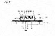
- Fig. 5 is a side view of the housing of the connector.
- a connector 11 As shown in Figs. 1 to 4 , a connector 11 according to the embodiment has a housing 12 and a cover 13 which is attached to the housing 12, and a wire harness 21 is connected to the connector 11.
- the wire harness 21 has a plurality of cables 22 in which electric wires are covered with resin, and a part in which these cables 22 are bundled by a sleeve 23 is a bundled part 24.
- Connection terminals 25 are connected to the ends of the cables 22 of the wire harness 21, respectively.
- the housing 12 is formed of resin or metal, and as shown in Fig. 5 , has a base part 31 and a connecting part 32 which is formed on the top of the base part 31.
- Mounting holes 33 are formed in the base part 31, and when bolts are inserted through these mounting holes 33, for example, the base part 31 can be fixed to a mounted part such as the frame of a vehicle.
- the connecting part 32 has a plurality of accommodating parts 34. As shown in Fig. 4 , these accommodating parts 34, when viewed from top, are formed to be multiple ones for each of the right and left sides (three for each in the embodiment) at opposite positions.
- One end side of the accommodating part 34 is a terminal holding part 35, and the upper side and the other end side of the accommodating part 34 are opened, and the other end side which is opened is an outlet 34a for the cable 22.
- the ends of the cables 22 of the wire harness 21 are inserted into these accommodating parts 34, and the connection terminals 25 which are provided at the ends of the cables 22 are respectively connected to the terminal holding parts 35.
- the cables 22 of the wire harness 21 are branched at the end of the wire harness 21, and are arranged towards the connector and from both sides of the connector 11 to the accommodating parts 34, respectively. Thereby, the cables 22 are curved between the bundled part 24 and the accommodating parts 34 of the connector 11.
- cable protecting projections 37 are formed at the edges at the outlet sides of the cables 22. These cable protecting projections 37 are formed to have an arc shaped cross section, and are formed at the edges of the walls 36 at the curving sides of the cables 22.
- a plurality of locking claws 38 are formed on side surfaces of the connecting part 32 of the housing 12.
- the cover 13 which is attached to the top surface of the housing 12 is formed of resin or metal and is provided with a cover plate 41 which covers the top surface of the connecting part 32 of the housing 12, and locking pieces 42 which are formed at both sides of the cover plate 41.
- a plurality of protrusions 43 which fit into the accommodating parts 34 of the connecting part 32 are formed on the surface of the cover plate 41 that faces the housing 12, and the connection terminals 25 of the cables 22 which are arranged in the accommodating parts 34 are pressed and held by these protrusions 43.
- Recesses 44 are formed at positions of the cover plate 41 that correspond to the edges of the accommodating parts 34.
- the locking pieces 42 have locking holes 45, respectively, and are projected to the direction of attaching to the housing 12.
- the locking claws 38 formed on the side surfaces of the connecting part 32 of the housing 12 are locked in the locking holes 45 of these locking pieces 42, and thereby the cover 13 is attached to the connecting part 32 of the housing 12.
- the spaces in the accommodating parts 34 are filled with holding members 51 which have elasticity.
- the holding members 51 are formed by filling filler into the accommodating parts 34, and making it solidify. After the ends of the cables 22 are accommodated in the accommodating parts 34 of the housing 12 and the cover 13 are attached, the filler is filled into the accommodating parts 34 from the recesses 44 of the cover 13 at the sides of the outlets 34a for the cables 22.
- the above-mentioned connector 11 has the plurality of accommodating parts 34 and the ends of the cables 22 are accommodated in these accommodating parts 34, respectively, a proper amount of filler can be smoothly filled into the accommodating parts 34, and the cables 22 can be well hold by the holding members 51.
- the ends of the cables 22 which are arranged in the accommodating parts 34 can be held by the holding members 51 which are filled into the accommodating parts 34 and solidified, and the degradation of the connection terminals 25 can be prevented by sealing the inside of the accommodating parts 34.
- the cable protecting projections 37 which are projected with an arc shaped cross section toward the cables 22 are formed at the edges of the walls 36, which form the accommodating parts 34 at the curving sides of the cables 22, at the outlet sides of the cables 22, for example, even if the cables 22 are pulled towards the walls 36 of the accommodating parts 34 during the filling and solidifying of the holding members 51 or the cables 22 are not well held because the holding members 51 deteriorate with time, the cables 22 are held by abutting against the cable protecting projections 37 which are formed with an arc shaped cross section.
- the directions of pulling out the cables 22 from the accommodating parts 34 are maintained along straight lines as much as possible by the cable protecting projections 37, the load of the cables 22 at the positions where the connection terminals 25 are connected can be suppressed, and defects, such as an open circuit in the positions where the connection terminals 25 are connected, also can be definitely prevented. Thereby, the flexibility of the directions of pulling out the cables 22 can be improved, and the wiring of the wire harness 21 can be facilitated.
Landscapes
- Chemical & Material Sciences (AREA)
- Dispersion Chemistry (AREA)
- Connector Housings Or Holding Contact Members (AREA)
- Details Of Connecting Devices For Male And Female Coupling (AREA)
- Transition And Organic Metals Composition Catalysts For Addition Polymerization (AREA)
Abstract
Description
- The invention is related to a connector to which cables of a wire harness or the like are connected.
- Conventionally, in a connector which accommodates ends of cables where connection terminals are provided, accommodating parts which accommodate the ends of the cables in a housing are waterproofed by filling a filler into the accommodating parts or using sealing materials or the like (for example, refer to PTLs 1 to 6).
-
- [PTL 1]
JP-A-07-254455 - [PTL 2]
JP-A-07-296883 - [PTL 3]
JP-A-08-124623 - [PTL 4]
JP-A-11-283695 - [PTL 5]
JP-A-05-91997 - [PTL 6]
JP-U-05-92975 - The cables have such a structure that the cables are pulled out from the accommodating parts of the housing of the connector. For this reason, it is likely that the cables pulled out from the accommodating parts contact with the edges of walls which form the accommodating parts and are damaged. Especially, when the filler or the sealing material in the accommodating parts deteriorates and the cables are not sufficiently held, the cables tend to move and the possibility of contacting with the edges of the walls of the accommodating parts increases. Further, the cables may move and contact with the edges of the walls of the accommodating parts before the filler is solidified.
- When the connector is carried in a vehicle or the like, since the cables pulled out from the accommodating parts of the connector are vibrated and moved, the damage due to the contact of the cables with the edges of the walls will appear notably.
- The invention is made in view of the problems mentioned above, and the object of the invention is to provide a connector which can prevent damage to cables, and hold and waterproof the ends of the cables.
- In order to achieve the purpose mentioned above, a connector according to the invention is characterized by the following (1) or (2).
- (1) A connector, comprising:
- an accommodating part which accommodates an end of a cable where a connection terminal is provided, wherein
- the end of the cable is held by elastic holding member which is filled and solidified in the accommodating part, and
- a cable protecting projection which has an arc shaped cross section and is projected towards the cable is formed at an edge of a wall which forms the accommodating part at an outlet side of the cable.
- (2) The connector according to the above (1), wherein
the cable pulled out from the accommodating part is arranged so as to be curved, and
a cable protecting projection is provided on the wall of the accommodating part at least at a curving side of the cable. - In the connector of the structure of the above-mentioned (1), the ends of the cables which are arranged in the accommodating parts can be held by the holding members which are filled into the accommodating parts and solidified, and the degradation of the connection terminals can be prevented by sealing the inside of the accommodating parts.
Since the cable protecting projections which are projected with an arc shaped cross section toward the cables are formed at the edges of the walls, which form the accommodating parts, at the outlet sides of the cables, for example, even if the cables are pulled towards the walls of the accommodating parts during the filling and solidifying of the holding members or the cables are not well held because the holding members deteriorate with time, the cables are held by abutting against the cable protecting projections which are projected with an arc shaped cross section. Therefore, the damage produced when the cables contact the edges of the walls of the accommodating parts can be prevented. Therefore, even if the connector is carried in a vehicle or the like, and the cables which are pulled out from the accommodating parts of the connector vibrate and move, the damage due to the contact of the cables with the edges of the walls can be definitely prevented.
In the connector of the structure of the above-mentioned (2), since the cables pulled out from the accommodating parts are arranged so as to be curved, and the cable protecting projections are provided on the walls of the accommodating parts at the curving sides of the cables, even if the cables are pulled towards the curving sides, damage produced when the cables contact with the edges of the walls of the accommodating parts can be prevented. - According to the invention, the connector can be provided which can prevent damage to cables, and hold and waterproof the ends of the cables.
- The invention is explained in brief above. Further, details of the invention will become more apparent after the embodiments of the invention described below are read with reference to the accompanying figures.
-
-
Fig. 1 is a perspective view of a connector according to an embodiment of the invention. -
Fig. 2 is an exploded perspective view of the connector according to the embodiment of the invention. -
Fig. 3 is a sectional view of the connector according to the embodiment of the invention. -
Fig. 4 is a top view of a housing of the connector in which cables of a wire harness are arranged. -
Fig. 5 is a side view of the housing of the connector. - Below, the embodiments of the invention are explained with reference to the figures.
-
Fig. 1 is a perspective view of a connector according to an embodiment of the invention,Fig. 2 is an exploded perspective view of the connector according to the embodiment of the invention,Fig. 3 is a sectional view of the connector according to the embodiment of the invention,Fig. 4 is a top view of a housing of the connector in which cables of a wire harness are arranged, andFig. 5 is a side view of the housing of the connector. - As shown in
Figs. 1 to 4 , aconnector 11 according to the embodiment has ahousing 12 and acover 13 which is attached to thehousing 12, and awire harness 21 is connected to theconnector 11. - The
wire harness 21 has a plurality ofcables 22 in which electric wires are covered with resin, and a part in which thesecables 22 are bundled by asleeve 23 is a bundledpart 24. -
Connection terminals 25 are connected to the ends of thecables 22 of thewire harness 21, respectively. - The
housing 12 is formed of resin or metal, and as shown inFig. 5 , has abase part 31 and a connectingpart 32 which is formed on the top of thebase part 31. -
Mounting holes 33 are formed in thebase part 31, and when bolts are inserted through thesemounting holes 33, for example, thebase part 31 can be fixed to a mounted part such as the frame of a vehicle. - The connecting
part 32 has a plurality ofaccommodating parts 34. As shown inFig. 4 , theseaccommodating parts 34, when viewed from top, are formed to be multiple ones for each of the right and left sides (three for each in the embodiment) at opposite positions. - One end side of the
accommodating part 34 is aterminal holding part 35, and the upper side and the other end side of theaccommodating part 34 are opened, and the other end side which is opened is anoutlet 34a for thecable 22. - The ends of the
cables 22 of thewire harness 21 are inserted into theseaccommodating parts 34, and theconnection terminals 25 which are provided at the ends of thecables 22 are respectively connected to theterminal holding parts 35. - The
cables 22 of thewire harness 21 are branched at the end of thewire harness 21, and are arranged towards the connector and from both sides of theconnector 11 to theaccommodating parts 34, respectively. Thereby, thecables 22 are curved between the bundledpart 24 and theaccommodating parts 34 of theconnector 11. - On
walls 36 which form theaccommodating parts 34,cable protecting projections 37 are formed at the edges at the outlet sides of thecables 22. Thesecable protecting projections 37 are formed to have an arc shaped cross section, and are formed at the edges of thewalls 36 at the curving sides of thecables 22. - A plurality of
locking claws 38 are formed on side surfaces of the connectingpart 32 of thehousing 12. - The
cover 13 which is attached to the top surface of thehousing 12 is formed of resin or metal and is provided with acover plate 41 which covers the top surface of the connectingpart 32 of thehousing 12, andlocking pieces 42 which are formed at both sides of thecover plate 41. - A plurality of
protrusions 43 which fit into theaccommodating parts 34 of the connectingpart 32 are formed on the surface of thecover plate 41 that faces thehousing 12, and theconnection terminals 25 of thecables 22 which are arranged in theaccommodating parts 34 are pressed and held by theseprotrusions 43.Recesses 44 are formed at positions of thecover plate 41 that correspond to the edges of theaccommodating parts 34. - The
locking pieces 42 have lockingholes 45, respectively, and are projected to the direction of attaching to thehousing 12. Thelocking claws 38 formed on the side surfaces of the connectingpart 32 of thehousing 12 are locked in thelocking holes 45 of theselocking pieces 42, and thereby thecover 13 is attached to the connectingpart 32 of thehousing 12. - In the
connector 11 of the above-mentioned structure, the spaces in theaccommodating parts 34 are filled with holdingmembers 51 which have elasticity. - The holding
members 51 are formed by filling filler into theaccommodating parts 34, and making it solidify. After the ends of thecables 22 are accommodated in theaccommodating parts 34 of thehousing 12 and thecover 13 are attached, the filler is filled into theaccommodating parts 34 from therecesses 44 of thecover 13 at the sides of theoutlets 34a for thecables 22. - While the
accommodating parts 34 are sealed by the holdingmembers 51 which have elasticity, the ends of thecables 22 where theconnection terminals 25 are provided are held. - Since the above-mentioned
connector 11 has the plurality ofaccommodating parts 34 and the ends of thecables 22 are accommodated in theseaccommodating parts 34, respectively, a proper amount of filler can be smoothly filled into theaccommodating parts 34, and thecables 22 can be well hold by the holdingmembers 51. - Thus, according to the
connector 11 in the above-mentioned embodiment, the ends of thecables 22 which are arranged in theaccommodating parts 34 can be held by the holdingmembers 51 which are filled into theaccommodating parts 34 and solidified, and the degradation of theconnection terminals 25 can be prevented by sealing the inside of theaccommodating parts 34. - Since the
cable protecting projections 37 which are projected with an arc shaped cross section toward thecables 22 are formed at the edges of thewalls 36, which form theaccommodating parts 34 at the curving sides of thecables 22, at the outlet sides of thecables 22, for example, even if thecables 22 are pulled towards thewalls 36 of theaccommodating parts 34 during the filling and solidifying of the holdingmembers 51 or thecables 22 are not well held because the holdingmembers 51 deteriorate with time, thecables 22 are held by abutting against thecable protecting projections 37 which are formed with an arc shaped cross section. - Therefore, the damage produced when the
cables 22 contact the edges of thewalls 36 of theaccommodating parts 34 can be prevented. Therefore, even if theconnector 11 is carried in a vehicle or the like, and thecables 22 which are pulled out from theaccommodating parts 34 of theconnector 11 vibrate and move, the damage due to the contact of thecables 22 with the edges of thewalls 36 can be definitely prevented. - That is, according to the above-mentioned
connector 11, while the ends of thecables 22 can be held and waterproofed, the damage to thecables 22 can be prevented. - Since the directions of pulling out the
cables 22 from theaccommodating parts 34 are maintained along straight lines as much as possible by thecable protecting projections 37, the load of thecables 22 at the positions where theconnection terminals 25 are connected can be suppressed, and defects, such as an open circuit in the positions where theconnection terminals 25 are connected, also can be definitely prevented. Thereby, the flexibility of the directions of pulling out thecables 22 can be improved, and the wiring of thewire harness 21 can be facilitated. - The invention is not restricted to the above-described embodiment, and suitable modifications, improvements and the like can be made. Moreover, the materials, shapes, dimensions, numerical values, forms, numbers, installation places and the like of the components are arbitrarily set as far as the invention can be attained, and not particularly restricted.
- Although the present invention is described in detail with reference to the embodiments, it is apparent that various modifications and amendments may be made by those skilled in the art without departing from the spirit and scope of the invention.
- This application is based on the Japanese patent application (patent application
2010-022209 -
- 11
- CONNECTOR
- 22
- CABLE
- 25
- CONNECTION TERMINAL
- 34
- ACCOMMODATING PART
- 36
- WALL
- 37
- CABLE PROTECTING PROJECTION
- 51
- HOLDING MEMBER
Claims (2)
- A connector, comprising:an accommodating part which accommodates an end of a cable where a connection terminal is provided, whereinthe end of the cable is held by elastic holding member which is filled and solidified in the accommodating part, anda cable protecting projection which has an arc shaped cross section and is projected towards the cable is formed at an edge of a wall which forms the accommodating part at an outlet side of the cable.
- The connector according to claim 1, wherein
the cable pulled out from the accommodating part is arranged so as to be curved, and
a cable protecting projection is provided on the wall of the accommodating part at least at a curving side of the cable.
Applications Claiming Priority (2)
| Application Number | Priority Date | Filing Date | Title |
|---|---|---|---|
| JP2010022209A JP5424484B2 (en) | 2010-02-03 | 2010-02-03 | connector |
| PCT/JP2011/052295 WO2011096497A1 (en) | 2010-02-03 | 2011-02-03 | Connector |
Publications (2)
| Publication Number | Publication Date |
|---|---|
| EP2533373A1 true EP2533373A1 (en) | 2012-12-12 |
| EP2533373A4 EP2533373A4 (en) | 2013-06-05 |
Family
ID=44355490
Family Applications (1)
| Application Number | Title | Priority Date | Filing Date |
|---|---|---|---|
| EP11739845.3A Withdrawn EP2533373A4 (en) | 2010-02-03 | 2011-02-03 | CONNECTOR |
Country Status (7)
| Country | Link |
|---|---|
| US (2) | US9011174B2 (en) |
| EP (1) | EP2533373A4 (en) |
| JP (1) | JP5424484B2 (en) |
| KR (1) | KR101340811B1 (en) |
| CN (1) | CN102742093B (en) |
| BR (1) | BR112012019510A2 (en) |
| WO (1) | WO2011096497A1 (en) |
Cited By (1)
| Publication number | Priority date | Publication date | Assignee | Title |
|---|---|---|---|---|
| FR3051985A1 (en) * | 2016-05-27 | 2017-12-01 | Valeo Vision | ELECTRIC WIRE GUIDING CONNECTOR, AND LUMINOUS DEVICE FOR MOTOR VEHICLE HAVING SUCH A CONNECTOR |
Families Citing this family (7)
| Publication number | Priority date | Publication date | Assignee | Title |
|---|---|---|---|---|
| US9356439B2 (en) * | 2013-09-26 | 2016-05-31 | Commscope, Inc. Of North Carolina | Patch cords for reduced-pair ethernet applications having strain relief units that resist rotational loads and related strain relief units and connectors |
| JP6557021B2 (en) * | 2015-02-17 | 2019-08-07 | スリーエム イノベイティブ プロパティズ カンパニー | Connector and connector assembly |
| RU2738407C2 (en) * | 2015-09-18 | 2020-12-11 | ШЕВРОН ФИЛЛИПС КЕМИКАЛ КОМПАНИ ЭлПи | Improved reactor for ethylene oligomerization/trimerisation/tetramerisation reactor |
| US10519077B2 (en) | 2015-09-18 | 2019-12-31 | Chevron Phillips Chemical Company Lp | Ethylene oligomerization/trimerization/tetramerization reactor |
| US10513473B2 (en) | 2015-09-18 | 2019-12-24 | Chevron Phillips Chemical Company Lp | Ethylene oligomerization/trimerization/tetramerization reactor |
| JP2019220248A (en) * | 2018-06-15 | 2019-12-26 | 住友電装株式会社 | Waterproof structure for multicore wire |
| NL2025563B1 (en) * | 2020-05-12 | 2021-11-30 | Microsoft Technology Licensing Llc | Connector bracket for a cable connector |
Family Cites Families (35)
| Publication number | Priority date | Publication date | Assignee | Title |
|---|---|---|---|---|
| US4150866A (en) * | 1977-08-26 | 1979-04-24 | Amp Incorporated | Environmentally sealed connector |
| JPS5921517U (en) * | 1982-08-02 | 1984-02-09 | 手島 信彦 | cord drawer |
| US4713021A (en) * | 1985-05-17 | 1987-12-15 | Amp Incorporated | Sealed electrical connector and method of using same |
| JPH0591997A (en) | 1991-09-30 | 1993-04-16 | Shimadzu Corp | Image treating system |
| US5266045A (en) * | 1991-10-28 | 1993-11-30 | Yazaki Corporation | Waterproof connector |
| JP2558758Y2 (en) | 1992-05-22 | 1998-01-14 | 矢崎総業株式会社 | Grommet with body earth structure |
| JP2525669Y2 (en) | 1992-05-26 | 1997-02-12 | 矢崎総業株式会社 | Waterproof connector |
| US5498172A (en) * | 1993-07-30 | 1996-03-12 | Sunx Kabushiki Kaisha | Electrical connector for interconnecting parallel multiconductor cables |
| JPH07254455A (en) | 1994-03-15 | 1995-10-03 | Sumitomo Wiring Syst Ltd | Connector having electronic part |
| JP2863083B2 (en) * | 1994-04-01 | 1999-03-03 | 矢崎総業株式会社 | Waterproof stopper for connector |
| DE69522488T2 (en) * | 1994-04-13 | 2002-05-16 | Sumitomo Wiring Systems, Ltd. | Sealing device and manufacturing method of a waterproof connector |
| JPH07296883A (en) | 1994-04-27 | 1995-11-10 | Yazaki Corp | Waterproof connector |
| JP3317587B2 (en) * | 1994-07-19 | 2002-08-26 | タイコエレクトロニクスアンプ株式会社 | Waterproof stopper and waterproof connector using the same |
| JP3060363B2 (en) | 1994-10-26 | 2000-07-10 | 矢崎総業株式会社 | Wire protection structure for resin-filled connectors |
| JPH09289057A (en) * | 1996-04-19 | 1997-11-04 | Yazaki Corp | Waterproof connector |
| CN1188996A (en) | 1996-11-15 | 1998-07-29 | 住友电装株式会社 | Connecting device for high-voltage cable |
| JP3388569B2 (en) * | 1997-03-10 | 2003-03-24 | 矢崎総業株式会社 | Waterproof connector |
| JP3547988B2 (en) | 1998-03-31 | 2004-07-28 | 矢崎総業株式会社 | Waterproof connector and waterproofing method |
| JP3540156B2 (en) * | 1998-06-10 | 2004-07-07 | 矢崎総業株式会社 | Waterproof connector and method of assembling the waterproof connector |
| JP3535034B2 (en) * | 1999-03-29 | 2004-06-07 | 矢崎総業株式会社 | Waterproof connector |
| JP3648405B2 (en) | 1999-06-18 | 2005-05-18 | 矢崎総業株式会社 | connector |
| ATE236180T1 (en) * | 1999-08-20 | 2003-04-15 | Basf Ag | BISIMIDINE COMPOUNDS AND THEIR TRANSITION METAL COMPLEXES AND THEIR USE AS CATALYSTS |
| US6722914B2 (en) * | 2000-01-27 | 2004-04-20 | Ideal Industries, Inc. | Wire connector with extension |
| EP1182741A1 (en) * | 2000-08-23 | 2002-02-27 | Delphi Technologies, Inc. | Electrical connector |
| JP2003068392A (en) | 2001-08-29 | 2003-03-07 | Tyco Electronics Amp Kk | Water-proof connector |
| US6679730B2 (en) * | 2002-05-29 | 2004-01-20 | Itt Manufacturing Enterprises, Inc. | Connector with overmold seal/robust latch |
| JP4035656B2 (en) * | 2002-12-18 | 2008-01-23 | 住友電装株式会社 | Rubber plug for waterproof connector |
| FR2893189B1 (en) * | 2005-11-08 | 2008-02-29 | Peugeot Citroen Automobiles Sa | DEVICE FOR INSULATING AN ELECTRICAL CONNECTION. |
| US7575458B2 (en) * | 2006-09-12 | 2009-08-18 | Baker Hughes Incorporated | Hi-dielectric debris seal for a pothead interface |
| AT504850B1 (en) * | 2007-02-12 | 2009-03-15 | Weingartner Bernhard Dipl Ing | ELECTRICAL CABLE WITH BOTH CABLE CONNECTED CABLE PLUG CONNECTORS |
| JP2010022209A (en) | 2008-07-15 | 2010-02-04 | Nihon Bio Energy Kk | Afforestation device and afforestation system using the same |
| JP5189998B2 (en) * | 2009-01-14 | 2013-04-24 | 株式会社ミツバ | Fuel supply device |
| EP2254203B1 (en) * | 2009-04-03 | 2015-05-20 | Sumitomo Wiring Systems, Ltd. | Resilient plug, fluid proof construction and connector |
| WO2011022384A1 (en) * | 2009-08-17 | 2011-02-24 | E. I. Du Pont De Nemours And Company | IMPROVED α-OLEFIN MANUFACTURING PROCESS |
| WO2011126784A1 (en) * | 2010-03-29 | 2011-10-13 | E. I. Du Pont De Nemours And Company | Improved ethylene polymerization process and polyolefin |
-
2010
- 2010-02-03 JP JP2010022209A patent/JP5424484B2/en not_active Expired - Fee Related
-
2011
- 2011-02-03 US US13/577,038 patent/US9011174B2/en not_active Expired - Fee Related
- 2011-02-03 CN CN201180008300.9A patent/CN102742093B/en not_active Expired - Fee Related
- 2011-02-03 EP EP11739845.3A patent/EP2533373A4/en not_active Withdrawn
- 2011-02-03 BR BR112012019510-7A patent/BR112012019510A2/en not_active IP Right Cessation
- 2011-02-03 KR KR20127020519A patent/KR101340811B1/en not_active Expired - Fee Related
- 2011-02-03 WO PCT/JP2011/052295 patent/WO2011096497A1/en not_active Ceased
- 2011-03-28 US US13/576,732 patent/US20120302809A1/en not_active Abandoned
Cited By (1)
| Publication number | Priority date | Publication date | Assignee | Title |
|---|---|---|---|---|
| FR3051985A1 (en) * | 2016-05-27 | 2017-12-01 | Valeo Vision | ELECTRIC WIRE GUIDING CONNECTOR, AND LUMINOUS DEVICE FOR MOTOR VEHICLE HAVING SUCH A CONNECTOR |
Also Published As
| Publication number | Publication date |
|---|---|
| US9011174B2 (en) | 2015-04-21 |
| JP5424484B2 (en) | 2014-02-26 |
| KR101340811B1 (en) | 2013-12-11 |
| CN102742093B (en) | 2015-09-09 |
| JP2011159579A (en) | 2011-08-18 |
| BR112012019510A2 (en) | 2018-03-13 |
| CN102742093A (en) | 2012-10-17 |
| US20120302809A1 (en) | 2012-11-29 |
| US20120302090A1 (en) | 2012-11-29 |
| WO2011096497A1 (en) | 2011-08-11 |
| EP2533373A4 (en) | 2013-06-05 |
| KR20120112738A (en) | 2012-10-11 |
Similar Documents
| Publication | Publication Date | Title |
|---|---|---|
| US9011174B2 (en) | Connector with cable protecting projection | |
| US9124079B2 (en) | Electric junction box | |
| US8851935B2 (en) | Electrical wire harness connector | |
| US9531113B2 (en) | Flat cable waterproofing connector and waterproofing connector structure for flat cable | |
| EP2874240B1 (en) | Connector and connector connection structure | |
| US20150129305A1 (en) | Shield connector | |
| KR20150017369A (en) | Connector terminal with sheathed wire attached, and water-stopping method for connector terminal with sheathed wire attached | |
| CN107210565A8 (en) | Shielded connector | |
| CN103688424A (en) | Shielded connectors for cables | |
| WO2012081671A1 (en) | Liquid-proof structure for wire harness | |
| KR20200071948A (en) | Integrated multipole connector | |
| EP2854232A1 (en) | Waterproof structure of wire harness with connector | |
| US9634450B2 (en) | Electric wire with connector and method for manufacturing the same | |
| KR20140034296A (en) | Waterproof connector and manufacturing method thereof | |
| US8881928B2 (en) | Casing cover | |
| JP2017123746A (en) | Protector and wire harness including the same | |
| JP2004119294A (en) | Sealing material fixing structure | |
| JP2011234427A (en) | Electrical connection box | |
| JP6788556B2 (en) | Electronic unit mounting structure | |
| CN109155510B (en) | Arrangement as a spare part of a junction box and method for installing the arrangement | |
| JP5851758B2 (en) | Flat cable waterproof connector | |
| CN110854770B (en) | Power supply terminal structure, electrical connection box and wiring harness | |
| CN108123252A (en) | Connector | |
| JP2009295945A (en) | Electronic unit integrated with wire harness, and method for manufacturing thereof | |
| US10971829B2 (en) | Connector and package body |
Legal Events
| Date | Code | Title | Description |
|---|---|---|---|
| PUAI | Public reference made under article 153(3) epc to a published international application that has entered the european phase |
Free format text: ORIGINAL CODE: 0009012 |
|
| 17P | Request for examination filed |
Effective date: 20120803 |
|
| AK | Designated contracting states |
Kind code of ref document: A1 Designated state(s): AL AT BE BG CH CY CZ DE DK EE ES FI FR GB GR HR HU IE IS IT LI LT LU LV MC MK MT NL NO PL PT RO RS SE SI SK SM TR |
|
| DAX | Request for extension of the european patent (deleted) | ||
| A4 | Supplementary search report drawn up and despatched |
Effective date: 20130506 |
|
| RIC1 | Information provided on ipc code assigned before grant |
Ipc: H01R 13/52 20060101ALI20130426BHEP Ipc: H01R 13/56 20060101AFI20130426BHEP |
|
| STAA | Information on the status of an ep patent application or granted ep patent |
Free format text: STATUS: THE APPLICATION HAS BEEN WITHDRAWN |
|
| 18W | Application withdrawn |
Effective date: 20160922 |