EP2533090A1 - Camera modul and method for assembling the same - Google Patents
Camera modul and method for assembling the same Download PDFInfo
- Publication number
- EP2533090A1 EP2533090A1 EP12171263A EP12171263A EP2533090A1 EP 2533090 A1 EP2533090 A1 EP 2533090A1 EP 12171263 A EP12171263 A EP 12171263A EP 12171263 A EP12171263 A EP 12171263A EP 2533090 A1 EP2533090 A1 EP 2533090A1
- Authority
- EP
- European Patent Office
- Prior art keywords
- lens
- cover part
- opening
- back cap
- camera module
- Prior art date
- Legal status (The legal status is an assumption and is not a legal conclusion. Google has not performed a legal analysis and makes no representation as to the accuracy of the status listed.)
- Granted
Links
Images


Classifications
-
- G—PHYSICS
- G02—OPTICS
- G02B—OPTICAL ELEMENTS, SYSTEMS OR APPARATUS
- G02B7/00—Mountings, adjusting means, or light-tight connections, for optical elements
- G02B7/02—Mountings, adjusting means, or light-tight connections, for optical elements for lenses
- G02B7/026—Mountings, adjusting means, or light-tight connections, for optical elements for lenses using retaining rings or springs
-
- G—PHYSICS
- G03—PHOTOGRAPHY; CINEMATOGRAPHY; ANALOGOUS TECHNIQUES USING WAVES OTHER THAN OPTICAL WAVES; ELECTROGRAPHY; HOLOGRAPHY
- G03B—APPARATUS OR ARRANGEMENTS FOR TAKING PHOTOGRAPHS OR FOR PROJECTING OR VIEWING THEM; APPARATUS OR ARRANGEMENTS EMPLOYING ANALOGOUS TECHNIQUES USING WAVES OTHER THAN OPTICAL WAVES; ACCESSORIES THEREFOR
- G03B17/00—Details of cameras or camera bodies; Accessories therefor
- G03B17/02—Bodies
- G03B17/12—Bodies with means for supporting objectives, supplementary lenses, filters, masks, or turrets
-
- G—PHYSICS
- G02—OPTICS
- G02B—OPTICAL ELEMENTS, SYSTEMS OR APPARATUS
- G02B7/00—Mountings, adjusting means, or light-tight connections, for optical elements
- G02B7/02—Mountings, adjusting means, or light-tight connections, for optical elements for lenses
-
- G—PHYSICS
- G03—PHOTOGRAPHY; CINEMATOGRAPHY; ANALOGOUS TECHNIQUES USING WAVES OTHER THAN OPTICAL WAVES; ELECTROGRAPHY; HOLOGRAPHY
- G03B—APPARATUS OR ARRANGEMENTS FOR TAKING PHOTOGRAPHS OR FOR PROJECTING OR VIEWING THEM; APPARATUS OR ARRANGEMENTS EMPLOYING ANALOGOUS TECHNIQUES USING WAVES OTHER THAN OPTICAL WAVES; ACCESSORIES THEREFOR
- G03B30/00—Camera modules comprising integrated lens units and imaging units, specially adapted for being embedded in other devices, e.g. mobile phones or vehicles
-
- H—ELECTRICITY
- H04—ELECTRIC COMMUNICATION TECHNIQUE
- H04N—PICTORIAL COMMUNICATION, e.g. TELEVISION
- H04N23/00—Cameras or camera modules comprising electronic image sensors; Control thereof
- H04N23/50—Constructional details
- H04N23/51—Housings
-
- Y—GENERAL TAGGING OF NEW TECHNOLOGICAL DEVELOPMENTS; GENERAL TAGGING OF CROSS-SECTIONAL TECHNOLOGIES SPANNING OVER SEVERAL SECTIONS OF THE IPC; TECHNICAL SUBJECTS COVERED BY FORMER USPC CROSS-REFERENCE ART COLLECTIONS [XRACs] AND DIGESTS
- Y10—TECHNICAL SUBJECTS COVERED BY FORMER USPC
- Y10T—TECHNICAL SUBJECTS COVERED BY FORMER US CLASSIFICATION
- Y10T29/00—Metal working
- Y10T29/49—Method of mechanical manufacture
- Y10T29/49826—Assembling or joining
Definitions
- the present invention relates to a camera module and a method for assembling the camera module.
- a mobile electronic device including a mobile phone or a notebook computer is equipped with an image capturing device such as a CCD image sensor or a CMOS image sensor.
- Such an image capturing device takes a subject in a form of a photograph or a video, stores an image data associated with the subject, and then edits or transmits the data if necessary.
- a modularized camera module becomes commercially available.
- the present invention provides a camera module and method capable of simplifying an assembly process and reducing the number of parts.
- a camera module comprising: a cover part having an opening formed therein, and a lens guide formed in the opening to prevent removal of a lens to an outside; a lens mounted to the opening of the cover part; and a back cap coming into close contact with the lens and mounted to the opening.
- the lens guide is integrated with the cover part into a single structure.
- an O-ring is interposed between the lens and the cover part.
- the back cap is fixed to the cover part.
- one side of the lens is in close contact with the lens guide, and the other side of the lens is in close contact with the back cap.
- the camera module further includes a protrusion provided on the lens guide to protrude toward the lens.
- an O-ring is mounted between the protrusion of the lens guide and the opening.
- a stepped portion is formed on an edge of an object-side of the lens, and the protrusion is in close contact with the stepped portion, so that the lens comes into close contact with the lens guide.
- a first stepped portion is formed in the opening of the cover part, and a second stepped portion is formed on an outer circumference of the back cap, so that when the back cap is mounted to the opening, the first stepped portion is engaged with the second stepped portion.
- a recess is formed in the cover part, the opening is formed inside the recess, and cover-part coupling portions are formed on the outer circumference of the back cap to be engaged with the recess and the opening of the cover part.
- a width of the opening is narrower than a width of the recess.
- the lens includes a projecting portion
- the back cap includes a depression to be engaged with the projecting portion, so that when the back cap is mounted to the opening of the cover part, the projecting portion of the lens is inserted into the depression of the back cap.
- a through hole is formed in the depression of the back cap to allow light of a subj ect to pass therethrough.
- the back cap is fastened to the cover part in a threaded manner.
- a method for assembling a camera module comprising: preparing a cover part, the cover part including an opening, a lens guide formed in the opening to prevent removal of a lens to an outside, a protrusion provided on the lens guide to come into close contact with the lens, and a groove formed between the protrusion of the lens guide and the cover part; fitting an O-ring into the groove; mounting the lens to the opening so that the lens comes into close contact with the O-ring; and fixing the back cap to the cover part after mounting the back cap to the opening to come into close contact with the lens.
- the fixing the back cap to the cover part is configured to fasten the back cap to the cover part in a threaded manner.
- one side of the lens comes into close contact with the lens guide, and the other side of the lens comes into close contact with the back cap.
- the fitting the O-ring into the groove is configured such that the O-ring is mounted between the protrusion of the lens guide and the opening.
- a first stepped portion is formed in the opening of the cover part, and a second stepped portion is formed on an outer circumference of the back cap, so that when the back cap is fixed to the opening, the first stepped portion is engaged with the second stepped portion.
- the lens includes a projecting portion
- the back cap includes a depression to be engaged with the projecting portion, so that when the back cap is fixed to the opening of the cover part, the projecting portion of the lens is securely inserted into the depression of the back cap.
- the camera module of the present invention is advantageous in that an assembly process can be simplified and the number of parts can be reduced by installing a lens in a cover part and fixing the lens with a back cap.
- the camera module of the present invention is advantageous in that a back cap is fastened to a cover part in a threaded manner, thus making an assembly process simple.
- the camera module of the present invention is advantageous in that it is assembled in a single direction, thus shortening assembly time.
- FIG. 1 is a schematic sectional view illustrating a camera module in accordance with an exemplary embodiment of the present invention.
- the camera module according to the present invention includes a cover part 100, a lens 200, and a back cap 300.
- An opening 110 is formed in the cover part 100, and a lens guide 120 is formed in the opening 110.
- the lens 200 is installed in the opening 110 of the cover part 100.
- the back cap 300 is brought into close contact with the lens 200 and is installed in the opening 110.
- the lens guide 120 prevents the lens 200 from moving out of the cover part 100.
- the lens guide 120 is formed on an inner wall of the opening 110 to block a portion of the opening 110 and thereby prevent removal of the lens 200 from the opening 110.
- the lens guide 120 takes a shape of a ring, and a width of the lens guide 120 is smaller than that of the opening 110, so that the removal of the lens 200 from the opening 110 is prevented by the lens guide 120.
- the lens guide 120 defines a width of an optical path of a subject incident into the lens 200.
- the lens guide 120 may be integrated with the cover part 100 into a single structure.
- the cover part 100 may be formed into a shape having the lens guide 120 thereon. In this way, the integration of the lens guide 120 and the cover part 100 may be implemented.
- an O-ring 130 may be interposed between the lens 200 and the cover part 100.
- the O-ring 130 prevents moisture and a pollution source from entering between the lens 200 and the cover part 100.
- the back cap 300 is fixed to the cover part 100 using an additional fastening means or fixing means.
- Various fastening means or fixing means may be applied to fix the back cap 300 to the cover part 100.
- one side of the lens 200 is inserted into the opening 110 of the cover part 100 to be in close contact with the lens guide 120, while the other side of the lens 200 is in close contact with the back cap 300. Thereby, the lens 200 is fixed to the cover part 100, so that optical alignment of the lens 200 is realized.
- the camera module of the present invention is advantageous in that the lens is installed in the cover part and is fixed by the back cap, so that an assembly process can be simplified and the number of parts can be reduced.
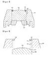
- FIG. 2 is a schematic sectional view illustrating a part of the camera module in accordance with the embodiment of the present invention.
- a protrusion 121 is provided on the lens guide 120 formed in the opening 110 of the cover part 100 to be in close contact with the lens 200.
- the protrusion 121 protrudes vertically from the lens guide 120 toward the lens 200.
- a surface of the lens 200 facing an object may be defined as an "object side”, while a surface of the lens 200 facing an image sensor may be defined as an "image-sensor side”.
- the camera module according to the present invention may have a stepped portion 210 along an edge of the object side of the lens 200.
- the protrusion 121 comes into contact with the stepped portion 210, thus allowing the lens 200 to come into close contact with the lens guide 120.
- the object side of the lens 200 has a lens portion 270 which is spaced apart from the edge of the lens 200, and the protrusion 121 of the lens guide 120 comes into close contact with the edge of the object-side of the lens 200.
- a groove 122 is formed between the protrusion 121 of the lens guide 120 and the cover part 100, and an O-ring (not shown) is fitted into the groove 122.
- the O-ring is fitted between the protrusion 121 of the lens guide 120 and the opening 110.
- FIG. 3 is a schematic sectional view illustrating a part of the camera module in accordance with the embodiment of the present invention.
- the camera module according to the embodiment of the present invention is configured to smoothly mount the back cap 300 to the cover part 100.
- a first stepped portion (see FIG. 4 ) is formed in the opening 110 of the cover part 100 into which the back cap 300 is installed, and a second stepped portion (see FIG. 4 ) is formed on an outer circumference of the back cap 300.
- first and second stepped portions are shaped to be engaged with each other when the back cap 300 is coupled to the cover part 100.
- a recess 150 is formed in the cover part 100, and the opening 110 of the cover part 100 is formed inside the recess 150.
- cover-part coupling portions 331 and 332 are formed on the outer circumference of the back cap 300, and are shaped to be engaged with the opening 110 and the recess 150 of the cover part 100, respectively.
- a width W1 of the opening 110 is narrower than a width W2 of the recess 150.
- a projecting portion 220 may be formed on the image-sensor side of the lens 200, and a depression 310 may be formed in the back cap 300 to be engaged with the projecting portion 220.
- the projecting portion 220 of the lens 200 is inserted into the depression 310 of the back cap 300.
- a through hole 320 may be formed in the depression 310 of the back cap 300 to serve as a path into which light of a subject is incident.
- an IR filter and an image sensor are sequentially arranged on the back cap 300.
- the light of the subject is incident into the image sensor via the through hole 320.
- FIG. 4 is a schematic sectional view illustrating a method for assembling a camera module in accordance with an exemplary embodiment of the present invention.
- the method for assembling the camera module according to the present invention first prepares the cover part 100.
- the opening 110 is formed in the cover part 100, and the lens guide 120 is formed in the opening 110 to prevent the removal of the lens 200 to the outside, and the protrusion 121 is formed on the lens guide 120 to come into close contact with the lens 200, and the groove 122 is formed between the protrusion 121 of the lens guide 120 and the cover part 100.
- the lens 200 is mounted to the opening 110 so that the lens 200 comes into close contact with the O-ring 130.
- the back cap 300 is mounted to the opening 110 to come into close contact with the lens 200, the back cap 300 is fixed to the cover part 100.
- the camera module of the present invention is advantageous in that the number of assembly parts is small and the assembly process is simple, so that a manufacturing cost is reduced.
- the camera module of the present invention is advantageous in that the assembly is performed in a single direction, so that assembly time can be shortened.
- FIG. 5 is a schematic partial sectional view illustrating an example of a method for fastening the back cap to the cover part of the camera module in accordance with the embodiment of the present invention.
- FIG. 5 shows one example of the methods.
- the recess 150 is formed in the cover part 100, and the opening 110 is formed inside the recess 150.
- cover-part coupling portions 331 and 332 engaging with the opening 110 and the recess 150 of the cover part 100 are formed on the outer circumference of the back cap 300.
- a first threaded portion 151 is formed on an inner surface of the recess 150, while a second threaded portion 332a is formed on the outer circumference of the back cap 300 to be engaged with the first threaded portion 151.
- the back cap 300 is provided with an area inserted into the opening 110 of the cover part 100, and an area inserted into the recess 150 of the cover part 100.
- the present invention is advantageous in that the back cap is fastened to the cover part in a threaded manner, so that the assembly process can be simplified.
- the present invention provides a camera module, which is capable of simplifying an assembly process and reducing the number of parts by installing a lens in a cover part and fixing the lens with a back cap.
Landscapes
- Physics & Mathematics (AREA)
- General Physics & Mathematics (AREA)
- Optics & Photonics (AREA)
- Engineering & Computer Science (AREA)
- Multimedia (AREA)
- Signal Processing (AREA)
- Lens Barrels (AREA)
- Studio Devices (AREA)
- Transforming Light Signals Into Electric Signals (AREA)
Abstract
Description
- The present invention relates to a camera module and a method for assembling the camera module.
- As various kinds of portable terminals have been widely popularized with the public and wireless internet service becomes commonly available, consumer demands for the portable terminals become diversified. Thereby, various kinds of peripheral devices have been applied to the portable terminals.
- Further, development of information and communication technology enhances improvement on data communication speed or expands data traffic. Currently, a mobile electronic device including a mobile phone or a notebook computer is equipped with an image capturing device such as a CCD image sensor or a CMOS image sensor.
- Such an image capturing device takes a subject in a form of a photograph or a video, stores an image data associated with the subject, and then edits or transmits the data if necessary. A modularized camera module becomes commercially available.
- Accordingly, the present invention provides a camera module and method capable of simplifying an assembly process and reducing the number of parts.
- In one general aspect of the present invention, there is provided a camera module, the camera module comprising: a cover part having an opening formed therein, and a lens guide formed in the opening to prevent removal of a lens to an outside; a lens mounted to the opening of the cover part; and a back cap coming into close contact with the lens and mounted to the opening.
- Preferably, the lens guide is integrated with the cover part into a single structure.
- Preferably, an O-ring is interposed between the lens and the cover part.
- Preferably, the back cap is fixed to the cover part.
- Preferably, one side of the lens is in close contact with the lens guide, and the other side of the lens is in close contact with the back cap.
- The camera module further includes a protrusion provided on the lens guide to protrude toward the lens.
- Preferably, an O-ring is mounted between the protrusion of the lens guide and the opening.
- Preferably, a stepped portion is formed on an edge of an object-side of the lens, and the protrusion is in close contact with the stepped portion, so that the lens comes into close contact with the lens guide.
- Preferably, a first stepped portion is formed in the opening of the cover part, and a second stepped portion is formed on an outer circumference of the back cap, so that when the back cap is mounted to the opening, the first stepped portion is engaged with the second stepped portion.
- Preferably, a recess is formed in the cover part, the opening is formed inside the recess, and cover-part coupling portions are formed on the outer circumference of the back cap to be engaged with the recess and the opening of the cover part.
- Preferably, a width of the opening is narrower than a width of the recess.
- Preferably, the lens includes a projecting portion, and the back cap includes a depression to be engaged with the projecting portion, so that when the back cap is mounted to the opening of the cover part, the projecting portion of the lens is inserted into the depression of the back cap.
- Preferably, a through hole is formed in the depression of the back cap to allow light of a subj ect to pass therethrough.
- Preferably, the back cap is fastened to the cover part in a threaded manner.
- In another general aspect of the present invention, there is provided a method for assembling a camera module, the method comprising: preparing a cover part, the cover part including an opening, a lens guide formed in the opening to prevent removal of a lens to an outside, a protrusion provided on the lens guide to come into close contact with the lens, and a groove formed between the protrusion of the lens guide and the cover part; fitting an O-ring into the groove; mounting the lens to the opening so that the lens comes into close contact with the O-ring; and fixing the back cap to the cover part after mounting the back cap to the opening to come into close contact with the lens. Preferably, the fixing the back cap to the cover part is configured to fasten the back cap to the cover part in a threaded manner.
- Preferably, after fixing the back cap to the cover part, one side of the lens comes into close contact with the lens guide, and the other side of the lens comes into close contact with the back cap.
- Preferably, the fitting the O-ring into the groove is configured such that the O-ring is mounted between the protrusion of the lens guide and the opening.
- Preferably, a first stepped portion is formed in the opening of the cover part, and a second stepped portion is formed on an outer circumference of the back cap, so that when the back cap is fixed to the opening, the first stepped portion is engaged with the second stepped portion.
- Preferably, the lens includes a projecting portion, and the back cap includes a depression to be engaged with the projecting portion, so that when the back cap is fixed to the opening of the cover part, the projecting portion of the lens is securely inserted into the depression of the back cap.
- The camera module of the present invention is advantageous in that an assembly process can be simplified and the number of parts can be reduced by installing a lens in a cover part and fixing the lens with a back cap.
- Further, the camera module of the present invention is advantageous in that a back cap is fastened to a cover part in a threaded manner, thus making an assembly process simple.
- Furthermore, the camera module of the present invention is advantageous in that it is assembled in a single direction, thus shortening assembly time.
-
-
FIG. 1 is a schematic sectional view illustrating a camera module in accordance with an exemplary embodiment of the present invention; -
FIG. 2 is a schematic sectional view illustrating a part of the camera module in accordance with the embodiment of the present invention; -
FIG. 3 is a schematic sectional view illustrating a part of the camera module in accordance with the embodiment of the present invention; -
FIG. 4 is a schematic sectional view illustrating a method for assembling a camera module in accordance with an exemplary embodiment of the present invention; and -
FIG. 5 is a schematic partial sectional view illustrating an example of a method for fastening a back cap to a cover part of the camera module in accordance with the embodiment of the present invention. - Hereinafter, embodiments of the present invention will be described with reference to the accompanying drawings.
-
FIG. 1 is a schematic sectional view illustrating a camera module in accordance with an exemplary embodiment of the present invention. - The camera module according to the present invention includes a
cover part 100, alens 200, and aback cap 300. Anopening 110 is formed in thecover part 100, and alens guide 120 is formed in theopening 110. Thelens 200 is installed in the opening 110 of thecover part 100. Theback cap 300 is brought into close contact with thelens 200 and is installed in the opening 110. - Here, the
lens guide 120 prevents thelens 200 from moving out of thecover part 100. - Further, the
lens guide 120 is formed on an inner wall of theopening 110 to block a portion of theopening 110 and thereby prevent removal of thelens 200 from theopening 110. - That is, the
lens guide 120 takes a shape of a ring, and a width of thelens guide 120 is smaller than that of theopening 110, so that the removal of thelens 200 from theopening 110 is prevented by thelens guide 120. - Further, the
lens guide 120 defines a width of an optical path of a subject incident into thelens 200. - Further, the
lens guide 120 may be integrated with thecover part 100 into a single structure. - For example, the
cover part 100 may be formed into a shape having thelens guide 120 thereon. In this way, the integration of thelens guide 120 and thecover part 100 may be implemented. - Further, an O-
ring 130 may be interposed between thelens 200 and thecover part 100. - The O-
ring 130 prevents moisture and a pollution source from entering between thelens 200 and thecover part 100. - Moreover, the
back cap 300 is fixed to thecover part 100 using an additional fastening means or fixing means. - Various fastening means or fixing means may be applied to fix the
back cap 300 to thecover part 100. - As such, one side of the
lens 200 is inserted into the opening 110 of thecover part 100 to be in close contact with thelens guide 120, while the other side of thelens 200 is in close contact with theback cap 300. Thereby, thelens 200 is fixed to thecover part 100, so that optical alignment of thelens 200 is realized. - As described above, the camera module of the present invention is advantageous in that the lens is installed in the cover part and is fixed by the back cap, so that an assembly process can be simplified and the number of parts can be reduced.
-
FIG. 2 is a schematic sectional view illustrating a part of the camera module in accordance with the embodiment of the present invention. - In the camera module of this embodiment, a
protrusion 121 is provided on thelens guide 120 formed in theopening 110 of thecover part 100 to be in close contact with thelens 200. - Here, the
protrusion 121 protrudes vertically from thelens guide 120 toward thelens 200. - Further, a surface of the
lens 200 facing an object may be defined as an "object side", while a surface of thelens 200 facing an image sensor may be defined as an "image-sensor side". - Here, the camera module according to the present invention may have a stepped
portion 210 along an edge of the object side of thelens 200. - That is, the
protrusion 121 comes into contact with the steppedportion 210, thus allowing thelens 200 to come into close contact with thelens guide 120. - The object side of the
lens 200 has alens portion 270 which is spaced apart from the edge of thelens 200, and theprotrusion 121 of thelens guide 120 comes into close contact with the edge of the object-side of thelens 200. - Further, a
groove 122 is formed between theprotrusion 121 of thelens guide 120 and thecover part 100, and an O-ring (not shown) is fitted into thegroove 122. - In other words, the O-ring is fitted between the
protrusion 121 of thelens guide 120 and theopening 110. -
FIG. 3 is a schematic sectional view illustrating a part of the camera module in accordance with the embodiment of the present invention. - The camera module according to the embodiment of the present invention is configured to smoothly mount the
back cap 300 to thecover part 100. - That is, a first stepped portion (see
FIG. 4 ) is formed in theopening 110 of thecover part 100 into which theback cap 300 is installed, and a second stepped portion (seeFIG. 4 ) is formed on an outer circumference of theback cap 300. Thereby, when theback cap 300 is inserted into theopening 110, the first stepped portion is engaged with the second stepped portion. - Here, the first and second stepped portions are shaped to be engaged with each other when the
back cap 300 is coupled to thecover part 100. - Turning back to
FIG. 3 , arecess 150 is formed in thecover part 100, and theopening 110 of thecover part 100 is formed inside therecess 150. - Further, cover-
part coupling portions back cap 300, and are shaped to be engaged with theopening 110 and therecess 150 of thecover part 100, respectively. - Here, a width W1 of the
opening 110 is narrower than a width W2 of therecess 150. - Further, according to other structural characteristics, a projecting
portion 220 may be formed on the image-sensor side of thelens 200, and adepression 310 may be formed in theback cap 300 to be engaged with the projectingportion 220. - Therefore, when the
back cap 300 is mounted to theopening 110 of thecover part 100, the projectingportion 220 of thelens 200 is inserted into thedepression 310 of theback cap 300. - Further, a through
hole 320 may be formed in thedepression 310 of theback cap 300 to serve as a path into which light of a subject is incident. - Also, an IR filter and an image sensor are sequentially arranged on the
back cap 300. - Furthermore, the light of the subject is incident into the image sensor via the through
hole 320. -
FIG. 4 is a schematic sectional view illustrating a method for assembling a camera module in accordance with an exemplary embodiment of the present invention. - The method for assembling the camera module according to the present invention first prepares the
cover part 100. Theopening 110 is formed in thecover part 100, and thelens guide 120 is formed in theopening 110 to prevent the removal of thelens 200 to the outside, and theprotrusion 121 is formed on thelens guide 120 to come into close contact with thelens 200, and thegroove 122 is formed between theprotrusion 121 of thelens guide 120 and thecover part 100. - Next, the O-
ring 130 is fitted into thegroove 122. - Subsequently, the
lens 200 is mounted to theopening 110 so that thelens 200 comes into close contact with the O-ring 130. - Further, after the
back cap 300 is mounted to theopening 110 to come into close contact with thelens 200, theback cap 300 is fixed to thecover part 100. - As such, the camera module of the present invention is advantageous in that the number of assembly parts is small and the assembly process is simple, so that a manufacturing cost is reduced.
- Further, the camera module of the present invention is advantageous in that the assembly is performed in a single direction, so that assembly time can be shortened.
-
FIG. 5 is a schematic partial sectional view illustrating an example of a method for fastening the back cap to the cover part of the camera module in accordance with the embodiment of the present invention. - There are various methods for fixing the
back cap 300 to thecover part 100, andFIG. 5 shows one example of the methods. - That is, the
recess 150 is formed in thecover part 100, and theopening 110 is formed inside therecess 150. - Further, the cover-
part coupling portions opening 110 and therecess 150 of thecover part 100 are formed on the outer circumference of theback cap 300. A first threadedportion 151 is formed on an inner surface of therecess 150, while a second threadedportion 332a is formed on the outer circumference of theback cap 300 to be engaged with the first threadedportion 151. - Here, the
back cap 300 is provided with an area inserted into theopening 110 of thecover part 100, and an area inserted into therecess 150 of thecover part 100. - Thus, if the
back cap 300 is inserted into theopening 110 of thecover part 100 and thereafter theback cap 300 is rotated, the first threadedportion 151 is engaged with the second threadedportion 332a. - Therefore, the present invention is advantageous in that the back cap is fastened to the cover part in a threaded manner, so that the assembly process can be simplified.
- Although the preferred embodiments of the present invention have been disclosed for illustrative purposes, those skilled in the art will appreciate that various modifications, additions and substitutions are possible, without departing from the scope and spirit of the invention as disclosed in the accompanying claims.
- As described above, the present invention provides a camera module, which is capable of simplifying an assembly process and reducing the number of parts by installing a lens in a cover part and fixing the lens with a back cap.
Claims (20)
- A camera module, comprising:a cover part having an opening formed therein, and a lens guide formed in the opening to prevent removal of a lens to an outside;a lens mounted to the opening of the cover part; anda back cap coming into close contact with the lens and mounted to the opening.
- The camera module as set forth in claim 1, wherein the lens guide is integrated with the cover part into a single structure.
- The camera module as set forth in claim 1, wherein an O-ring is interposed between the lens and the cover part.
- The camera module as set forth in claim 1, wherein the back cap is fixed to the cover part.
- The camera module as set forth in claim 1, wherein one side of the lens is in close contact with the lens guide, and the other side of the lens is in close contact with the back cap.
- The camera module as set forth in claim 1, further comprising:a protrusion provided on the lens guide to protrude toward the lens.
- The camera module as set forth in claim 6, wherein an O-ring is mounted between the protrusion of the lens guide and the opening.
- The camera module as set forth in claim 6, wherein a stepped portion is formed on an edge of an object-side of the lens, and the protrusion is in close contact with the stepped portion, so that the lens comes into close contact with the lens guide.
- The camera module as set forth in claim 1, wherein a first stepped portion is formed in the opening of the cover part, and a second stepped portion is formed on an outer circumference of the back cap, so that when the back cap is mounted to the opening, the first stepped portion is engaged with the second stepped portion.
- The camera module as set forth in claim 1, wherein a recess is formed in the cover part, the opening is formed inside the recess, and cover-part coupling portions are formed on the outer circumference of the back cap to be engaged with the recess and the opening of the cover part.
- The camera module as set forth in claim 10, wherein a width of the opening is narrower than a width of the recess.
- The camera module as set forth in claim 1, wherein the lens includes a projecting portion, and the back cap includes a depression to be engaged with the projecting portion, so that when the back cap is mounted to the opening of the cover part, the projecting portion of the lens is inserted into the depression of the back cap.
- The camera module as set forth in claim 12, wherein a through hole is formed in the depression of the back cap to allow light of a subject to pass therethrough.
- The camera module as set forth in claim 1, wherein the back cap is fastened to the cover part in a threaded manner.
- A method for assembling a camera module, comprising:
preparing a cover part, the cover part including an opening, a lens guide formed in the opening to prevent removal of a lens to an outside, a protrusion provided on the lens guide to come into close contact with the lens, and a groove formed between the protrusion of the lens guide and the cover part;
fitting an O-ring into the groove;
mounting the lens to the opening so that the lens comes into close contact with the O-ring; and
fixing the back cap to the cover part after mounting the back cap to the opening to come into close contact with the lens. - The method as set forth in claim 15, wherein the step of fixing the back cap to the cover part is configured to fasten the back cap to the cover part in a threaded manner.
- The method as set forth in claim 15, wherein after fixing the back cap to the cover part, one side of the lens comes into close contact with the lens guide, and the other side of the lens comes into close contact with the back cap.
- The method as set forth in claim 15, wherein the step of fitting the O-ring into the groove is configured such that the O-ring is mounted between the protrusion of the lens guide and the opening.
- The method as set forth in claim 15, wherein a first stepped portion is formed in the opening of the cover part, and a second stepped portion is formed on an outer circumference of the back cap, so that when the back cap is fixed to the opening, the first stepped portion is engaged with the second stepped portion.
- The method as set forth in claim 15, wherein the lens includes a projecting portion, and the back cap includes a depression to be engaged with the projecting portion, so that when the back cap is fixed to the opening of the cover part, the projecting portion of the lens is securely inserted into the depression of the back cap.
Applications Claiming Priority (1)
| Application Number | Priority Date | Filing Date | Title |
|---|---|---|---|
| KR1020110054475A KR101825747B1 (en) | 2011-06-07 | 2011-06-07 | Camera module and method for assembling the same |
Publications (2)
| Publication Number | Publication Date |
|---|---|
| EP2533090A1 true EP2533090A1 (en) | 2012-12-12 |
| EP2533090B1 EP2533090B1 (en) | 2014-06-18 |
Family
ID=46201500
Family Applications (1)
| Application Number | Title | Priority Date | Filing Date |
|---|---|---|---|
| EP12171263.2A Active EP2533090B1 (en) | 2011-06-07 | 2012-06-08 | Camera modul and method for assembling the same |
Country Status (4)
| Country | Link |
|---|---|
| US (2) | US9235107B2 (en) |
| EP (1) | EP2533090B1 (en) |
| KR (1) | KR101825747B1 (en) |
| WO (1) | WO2012169787A2 (en) |
Cited By (3)
| Publication number | Priority date | Publication date | Assignee | Title |
|---|---|---|---|---|
| WO2019061121A1 (en) * | 2017-09-28 | 2019-04-04 | 深圳传音制造有限公司 | Front camera sealed mounting structure and terminal |
| CN109884764A (en) * | 2017-12-06 | 2019-06-14 | 深圳光峰科技股份有限公司 | Lens module and projection device |
| CN110632809A (en) * | 2018-06-25 | 2019-12-31 | 三赢科技(深圳)有限公司 | camera module |
Families Citing this family (5)
| Publication number | Priority date | Publication date | Assignee | Title |
|---|---|---|---|---|
| JP6523172B2 (en) * | 2014-02-12 | 2019-05-29 | 日本電産サンキョー株式会社 | Lens unit and imaging device |
| JP6192560B2 (en) * | 2014-02-13 | 2017-09-06 | キヤノン株式会社 | Lens barrel and optical apparatus having the same |
| CN106896463B (en) * | 2015-12-17 | 2020-07-31 | 宁波舜宇车载光学技术有限公司 | Optical lens for vehicle-mounted optical imaging system |
| CN109073853B (en) * | 2016-03-23 | 2021-11-02 | 天津欧菲光电有限公司 | lens unit |
| US20180315894A1 (en) * | 2017-04-26 | 2018-11-01 | Advanced Semiconductor Engineering, Inc. | Semiconductor device package and a method of manufacturing the same |
Citations (4)
| Publication number | Priority date | Publication date | Assignee | Title |
|---|---|---|---|---|
| JP2002082271A (en) * | 2000-06-27 | 2002-03-22 | Milestone Kk | Shooting lens body |
| US20030137595A1 (en) * | 1997-05-16 | 2003-07-24 | Taizo Takachi | Image pickup device and camera |
| US20060181633A1 (en) * | 2005-02-16 | 2006-08-17 | Samsung Electro-Mechanics Co., Ltd. | Camera module |
| US20110279675A1 (en) * | 2010-03-10 | 2011-11-17 | Smk Corporation | Camera module |
Family Cites Families (18)
| Publication number | Priority date | Publication date | Assignee | Title |
|---|---|---|---|---|
| DE19924849C1 (en) * | 1999-05-29 | 2000-07-20 | Leica Camera Ag | Mounting to hold a centered lens has a structured cut-back groove with an elastic ring unit to lock the chamfered surface of the lens in a secure fit without lens damage |
| KR20030020483A (en) | 2001-08-29 | 2003-03-10 | 에스케이 텔레콤주식회사 | Lock with packing for preventing from rusting |
| US7002759B2 (en) * | 2003-03-20 | 2006-02-21 | Pentax Corporation | Lens unit for multibeam scanning device |
| KR20040085693A (en) | 2003-04-01 | 2004-10-08 | 카스크테크놀러지 주식회사 | Small camera optical system using in portable communication apparatus |
| JP3835619B2 (en) | 2004-02-09 | 2006-10-18 | 京セラ株式会社 | Imaging device |
| DE102005022594A1 (en) * | 2004-05-18 | 2006-01-19 | Citizen Electronics Co., Ltd., Fujiyoshida | Imaging device |
| DE102004049871B4 (en) * | 2004-10-13 | 2017-05-24 | Robert Bosch Gmbh | Method for producing an objective receptacle for a lens of a camera and camera for motor vehicle applications |
| KR100836134B1 (en) | 2007-02-07 | 2008-06-09 | 삼성전기주식회사 | Camera module |
| JP5026198B2 (en) * | 2007-08-28 | 2012-09-12 | 日立マクセル株式会社 | Lens unit, lens module, camera module, and method for manufacturing camera module mounted circuit board |
| US8411192B2 (en) * | 2007-11-15 | 2013-04-02 | Sharp Kabushiki Kaisha | Image capturing module, method for manufacturing the image capturing module, and electronic information device |
| JP2009216774A (en) | 2008-03-07 | 2009-09-24 | Konica Minolta Opto Inc | Optical component and imaging unit |
| JP5169361B2 (en) * | 2008-03-21 | 2013-03-27 | ソニー株式会社 | The camera module |
| EP2357503B1 (en) * | 2008-11-28 | 2018-10-24 | Sumitomo Electric Industries, Ltd. | Lens unit and infrared lens unit for mounting on vehicle |
| CA2780910A1 (en) * | 2009-11-23 | 2011-05-26 | Jerry Dean Wright | Face protector lens assembly and method of use |
| US20120069165A1 (en) * | 2010-09-16 | 2012-03-22 | Seung-Lyul Choi | Location-based av flashlight and method of displaying map related video thereof |
| US8308379B2 (en) * | 2010-12-01 | 2012-11-13 | Digitaloptics Corporation | Three-pole tilt control system for camera module |
| WO2012149206A2 (en) * | 2011-04-29 | 2012-11-01 | xDEV, INC. | Protective cover for an electronic device |
| EP2785044B1 (en) * | 2013-03-26 | 2017-10-18 | Samsung Electro-Mechanics Co., Ltd | Camera module |
-
2011
- 2011-06-07 KR KR1020110054475A patent/KR101825747B1/en active Active
-
2012
- 2012-06-07 US US14/123,834 patent/US9235107B2/en active Active
- 2012-06-07 WO PCT/KR2012/004478 patent/WO2012169787A2/en not_active Ceased
- 2012-06-08 EP EP12171263.2A patent/EP2533090B1/en active Active
-
2015
- 2015-12-18 US US14/975,328 patent/US9692952B2/en active Active
Patent Citations (4)
| Publication number | Priority date | Publication date | Assignee | Title |
|---|---|---|---|---|
| US20030137595A1 (en) * | 1997-05-16 | 2003-07-24 | Taizo Takachi | Image pickup device and camera |
| JP2002082271A (en) * | 2000-06-27 | 2002-03-22 | Milestone Kk | Shooting lens body |
| US20060181633A1 (en) * | 2005-02-16 | 2006-08-17 | Samsung Electro-Mechanics Co., Ltd. | Camera module |
| US20110279675A1 (en) * | 2010-03-10 | 2011-11-17 | Smk Corporation | Camera module |
Cited By (4)
| Publication number | Priority date | Publication date | Assignee | Title |
|---|---|---|---|---|
| WO2019061121A1 (en) * | 2017-09-28 | 2019-04-04 | 深圳传音制造有限公司 | Front camera sealed mounting structure and terminal |
| CN109884764A (en) * | 2017-12-06 | 2019-06-14 | 深圳光峰科技股份有限公司 | Lens module and projection device |
| CN110632809A (en) * | 2018-06-25 | 2019-12-31 | 三赢科技(深圳)有限公司 | camera module |
| CN110632809B (en) * | 2018-06-25 | 2021-09-21 | 三赢科技(深圳)有限公司 | Camera module |
Also Published As
| Publication number | Publication date |
|---|---|
| KR101825747B1 (en) | 2018-02-05 |
| EP2533090B1 (en) | 2014-06-18 |
| US9235107B2 (en) | 2016-01-12 |
| WO2012169787A2 (en) | 2012-12-13 |
| KR20120135646A (en) | 2012-12-17 |
| WO2012169787A3 (en) | 2013-03-07 |
| US9692952B2 (en) | 2017-06-27 |
| US20140212121A1 (en) | 2014-07-31 |
| US20160105594A1 (en) | 2016-04-14 |
Similar Documents
| Publication | Publication Date | Title |
|---|---|---|
| US9692952B2 (en) | Camera module and method for assembling the same | |
| US8436937B2 (en) | Camera module having socket with protrusion and method for assembling the same | |
| US8002481B2 (en) | Camera protecting assembly and assembling method thereof | |
| KR20080049668A (en) | Camera Module and Imager | |
| CN114114480A (en) | Camera module and optical apparatus including the same | |
| CN112492129B (en) | Camera Modules and Electronic Equipment | |
| US11714252B2 (en) | Lens unit, processing method for lens unit and electronic device | |
| CN111083341A (en) | camera module | |
| US9232031B1 (en) | Computing device components and assembly | |
| US20190253594A1 (en) | Imaging Camera | |
| CN113194218A (en) | Camera module manufacturing method and electronic product manufacturing method | |
| CN113194220A (en) | Camera module and electronic product | |
| JP2004147032A (en) | Small imaging module | |
| CN107483797A (en) | Covers, camera components and terminal equipment | |
| KR101428045B1 (en) | Camera module | |
| KR100856572B1 (en) | Camera module | |
| EP2667585B1 (en) | Combined camera and flash lens | |
| US20100283891A1 (en) | Method of setting position of imaging device | |
| CN211557354U (en) | Camera module | |
| JP2008203696A (en) | Lens arrangement structure, camera module, and electronic device | |
| CN211791706U (en) | Camera module and electronic product | |
| CN211791705U (en) | Camera module | |
| US8659842B1 (en) | Image capturing device and assembling method thereof | |
| CN114500815B (en) | Camera modules and electronic equipment | |
| KR101963270B1 (en) | Camera module |
Legal Events
| Date | Code | Title | Description |
|---|---|---|---|
| PUAI | Public reference made under article 153(3) epc to a published international application that has entered the european phase |
Free format text: ORIGINAL CODE: 0009012 |
|
| AK | Designated contracting states |
Kind code of ref document: A1 Designated state(s): AL AT BE BG CH CY CZ DE DK EE ES FI FR GB GR HR HU IE IS IT LI LT LU LV MC MK MT NL NO PL PT RO RS SE SI SK SM TR |
|
| AX | Request for extension of the european patent |
Extension state: BA ME |
|
| 17P | Request for examination filed |
Effective date: 20130611 |
|
| RBV | Designated contracting states (corrected) |
Designated state(s): AL AT BE BG CH CY CZ DE DK EE ES FI FR GB GR HR HU IE IS IT LI LT LU LV MC MK MT NL NO PL PT RO RS SE SI SK SM TR |
|
| 17Q | First examination report despatched |
Effective date: 20130712 |
|
| GRAP | Despatch of communication of intention to grant a patent |
Free format text: ORIGINAL CODE: EPIDOSNIGR1 |
|
| INTG | Intention to grant announced |
Effective date: 20140110 |
|
| GRAS | Grant fee paid |
Free format text: ORIGINAL CODE: EPIDOSNIGR3 |
|
| GRAA | (expected) grant |
Free format text: ORIGINAL CODE: 0009210 |
|
| AK | Designated contracting states |
Kind code of ref document: B1 Designated state(s): AL AT BE BG CH CY CZ DE DK EE ES FI FR GB GR HR HU IE IS IT LI LT LU LV MC MK MT NL NO PL PT RO RS SE SI SK SM TR |
|
| REG | Reference to a national code |
Ref country code: GB Ref legal event code: FG4D |
|
| REG | Reference to a national code |
Ref country code: CH Ref legal event code: EP |
|
| REG | Reference to a national code |
Ref country code: AT Ref legal event code: REF Ref document number: 673655 Country of ref document: AT Kind code of ref document: T Effective date: 20140715 |
|
| REG | Reference to a national code |
Ref country code: IE Ref legal event code: FG4D |
|
| REG | Reference to a national code |
Ref country code: DE Ref legal event code: R096 Ref document number: 602012002112 Country of ref document: DE Effective date: 20140731 |
|
| PG25 | Lapsed in a contracting state [announced via postgrant information from national office to epo] |
Ref country code: LT Free format text: LAPSE BECAUSE OF FAILURE TO SUBMIT A TRANSLATION OF THE DESCRIPTION OR TO PAY THE FEE WITHIN THE PRESCRIBED TIME-LIMIT Effective date: 20140618 Ref country code: GR Free format text: LAPSE BECAUSE OF FAILURE TO SUBMIT A TRANSLATION OF THE DESCRIPTION OR TO PAY THE FEE WITHIN THE PRESCRIBED TIME-LIMIT Effective date: 20140919 Ref country code: NO Free format text: LAPSE BECAUSE OF FAILURE TO SUBMIT A TRANSLATION OF THE DESCRIPTION OR TO PAY THE FEE WITHIN THE PRESCRIBED TIME-LIMIT Effective date: 20140918 Ref country code: CY Free format text: LAPSE BECAUSE OF FAILURE TO SUBMIT A TRANSLATION OF THE DESCRIPTION OR TO PAY THE FEE WITHIN THE PRESCRIBED TIME-LIMIT Effective date: 20140618 Ref country code: FI Free format text: LAPSE BECAUSE OF FAILURE TO SUBMIT A TRANSLATION OF THE DESCRIPTION OR TO PAY THE FEE WITHIN THE PRESCRIBED TIME-LIMIT Effective date: 20140618 |
|
| REG | Reference to a national code |
Ref country code: NL Ref legal event code: VDEP Effective date: 20140618 |
|
| REG | Reference to a national code |
Ref country code: AT Ref legal event code: MK05 Ref document number: 673655 Country of ref document: AT Kind code of ref document: T Effective date: 20140618 |
|
| REG | Reference to a national code |
Ref country code: LT Ref legal event code: MG4D |
|
| PG25 | Lapsed in a contracting state [announced via postgrant information from national office to epo] |
Ref country code: SE Free format text: LAPSE BECAUSE OF FAILURE TO SUBMIT A TRANSLATION OF THE DESCRIPTION OR TO PAY THE FEE WITHIN THE PRESCRIBED TIME-LIMIT Effective date: 20140618 Ref country code: LV Free format text: LAPSE BECAUSE OF FAILURE TO SUBMIT A TRANSLATION OF THE DESCRIPTION OR TO PAY THE FEE WITHIN THE PRESCRIBED TIME-LIMIT Effective date: 20140618 Ref country code: HR Free format text: LAPSE BECAUSE OF FAILURE TO SUBMIT A TRANSLATION OF THE DESCRIPTION OR TO PAY THE FEE WITHIN THE PRESCRIBED TIME-LIMIT Effective date: 20140618 Ref country code: RS Free format text: LAPSE BECAUSE OF FAILURE TO SUBMIT A TRANSLATION OF THE DESCRIPTION OR TO PAY THE FEE WITHIN THE PRESCRIBED TIME-LIMIT Effective date: 20140618 |
|
| PG25 | Lapsed in a contracting state [announced via postgrant information from national office to epo] |
Ref country code: RO Free format text: LAPSE BECAUSE OF FAILURE TO SUBMIT A TRANSLATION OF THE DESCRIPTION OR TO PAY THE FEE WITHIN THE PRESCRIBED TIME-LIMIT Effective date: 20140618 Ref country code: EE Free format text: LAPSE BECAUSE OF FAILURE TO SUBMIT A TRANSLATION OF THE DESCRIPTION OR TO PAY THE FEE WITHIN THE PRESCRIBED TIME-LIMIT Effective date: 20140618 Ref country code: CZ Free format text: LAPSE BECAUSE OF FAILURE TO SUBMIT A TRANSLATION OF THE DESCRIPTION OR TO PAY THE FEE WITHIN THE PRESCRIBED TIME-LIMIT Effective date: 20140618 Ref country code: SK Free format text: LAPSE BECAUSE OF FAILURE TO SUBMIT A TRANSLATION OF THE DESCRIPTION OR TO PAY THE FEE WITHIN THE PRESCRIBED TIME-LIMIT Effective date: 20140618 Ref country code: ES Free format text: LAPSE BECAUSE OF FAILURE TO SUBMIT A TRANSLATION OF THE DESCRIPTION OR TO PAY THE FEE WITHIN THE PRESCRIBED TIME-LIMIT Effective date: 20140618 Ref country code: PT Free format text: LAPSE BECAUSE OF FAILURE TO SUBMIT A TRANSLATION OF THE DESCRIPTION OR TO PAY THE FEE WITHIN THE PRESCRIBED TIME-LIMIT Effective date: 20141020 |
|
| PG25 | Lapsed in a contracting state [announced via postgrant information from national office to epo] |
Ref country code: PL Free format text: LAPSE BECAUSE OF FAILURE TO SUBMIT A TRANSLATION OF THE DESCRIPTION OR TO PAY THE FEE WITHIN THE PRESCRIBED TIME-LIMIT Effective date: 20140618 Ref country code: IS Free format text: LAPSE BECAUSE OF FAILURE TO SUBMIT A TRANSLATION OF THE DESCRIPTION OR TO PAY THE FEE WITHIN THE PRESCRIBED TIME-LIMIT Effective date: 20141018 Ref country code: AT Free format text: LAPSE BECAUSE OF FAILURE TO SUBMIT A TRANSLATION OF THE DESCRIPTION OR TO PAY THE FEE WITHIN THE PRESCRIBED TIME-LIMIT Effective date: 20140618 Ref country code: NL Free format text: LAPSE BECAUSE OF FAILURE TO SUBMIT A TRANSLATION OF THE DESCRIPTION OR TO PAY THE FEE WITHIN THE PRESCRIBED TIME-LIMIT Effective date: 20140618 |
|
| REG | Reference to a national code |
Ref country code: DE Ref legal event code: R097 Ref document number: 602012002112 Country of ref document: DE |
|
| PLBE | No opposition filed within time limit |
Free format text: ORIGINAL CODE: 0009261 |
|
| STAA | Information on the status of an ep patent application or granted ep patent |
Free format text: STATUS: NO OPPOSITION FILED WITHIN TIME LIMIT |
|
| PG25 | Lapsed in a contracting state [announced via postgrant information from national office to epo] |
Ref country code: DK Free format text: LAPSE BECAUSE OF FAILURE TO SUBMIT A TRANSLATION OF THE DESCRIPTION OR TO PAY THE FEE WITHIN THE PRESCRIBED TIME-LIMIT Effective date: 20140618 Ref country code: IT Free format text: LAPSE BECAUSE OF FAILURE TO SUBMIT A TRANSLATION OF THE DESCRIPTION OR TO PAY THE FEE WITHIN THE PRESCRIBED TIME-LIMIT Effective date: 20140618 |
|
| 26N | No opposition filed |
Effective date: 20150319 |
|
| PG25 | Lapsed in a contracting state [announced via postgrant information from national office to epo] |
Ref country code: BE Free format text: LAPSE BECAUSE OF FAILURE TO SUBMIT A TRANSLATION OF THE DESCRIPTION OR TO PAY THE FEE WITHIN THE PRESCRIBED TIME-LIMIT Effective date: 20140618 |
|
| PG25 | Lapsed in a contracting state [announced via postgrant information from national office to epo] |
Ref country code: SI Free format text: LAPSE BECAUSE OF FAILURE TO SUBMIT A TRANSLATION OF THE DESCRIPTION OR TO PAY THE FEE WITHIN THE PRESCRIBED TIME-LIMIT Effective date: 20140618 |
|
| PG25 | Lapsed in a contracting state [announced via postgrant information from national office to epo] |
Ref country code: MC Free format text: LAPSE BECAUSE OF FAILURE TO SUBMIT A TRANSLATION OF THE DESCRIPTION OR TO PAY THE FEE WITHIN THE PRESCRIBED TIME-LIMIT Effective date: 20140618 |
|
| REG | Reference to a national code |
Ref country code: CH Ref legal event code: PL |
|
| PG25 | Lapsed in a contracting state [announced via postgrant information from national office to epo] |
Ref country code: LU Free format text: LAPSE BECAUSE OF FAILURE TO SUBMIT A TRANSLATION OF THE DESCRIPTION OR TO PAY THE FEE WITHIN THE PRESCRIBED TIME-LIMIT Effective date: 20150608 |
|
| REG | Reference to a national code |
Ref country code: IE Ref legal event code: MM4A |
|
| PG25 | Lapsed in a contracting state [announced via postgrant information from national office to epo] |
Ref country code: LI Free format text: LAPSE BECAUSE OF NON-PAYMENT OF DUE FEES Effective date: 20150630 Ref country code: IE Free format text: LAPSE BECAUSE OF NON-PAYMENT OF DUE FEES Effective date: 20150608 Ref country code: CH Free format text: LAPSE BECAUSE OF NON-PAYMENT OF DUE FEES Effective date: 20150630 |
|
| REG | Reference to a national code |
Ref country code: FR Ref legal event code: PLFP Year of fee payment: 5 |
|
| PG25 | Lapsed in a contracting state [announced via postgrant information from national office to epo] |
Ref country code: MT Free format text: LAPSE BECAUSE OF FAILURE TO SUBMIT A TRANSLATION OF THE DESCRIPTION OR TO PAY THE FEE WITHIN THE PRESCRIBED TIME-LIMIT Effective date: 20140618 |
|
| REG | Reference to a national code |
Ref country code: FR Ref legal event code: PLFP Year of fee payment: 6 |
|
| PG25 | Lapsed in a contracting state [announced via postgrant information from national office to epo] |
Ref country code: HU Free format text: LAPSE BECAUSE OF FAILURE TO SUBMIT A TRANSLATION OF THE DESCRIPTION OR TO PAY THE FEE WITHIN THE PRESCRIBED TIME-LIMIT; INVALID AB INITIO Effective date: 20120608 |
|
| PG25 | Lapsed in a contracting state [announced via postgrant information from national office to epo] |
Ref country code: BG Free format text: LAPSE BECAUSE OF EXPIRATION OF PROTECTION Effective date: 20150630 |
|
| PG25 | Lapsed in a contracting state [announced via postgrant information from national office to epo] |
Ref country code: SM Free format text: LAPSE BECAUSE OF FAILURE TO SUBMIT A TRANSLATION OF THE DESCRIPTION OR TO PAY THE FEE WITHIN THE PRESCRIBED TIME-LIMIT Effective date: 20140618 |
|
| PG25 | Lapsed in a contracting state [announced via postgrant information from national office to epo] |
Ref country code: TR Free format text: LAPSE BECAUSE OF FAILURE TO SUBMIT A TRANSLATION OF THE DESCRIPTION OR TO PAY THE FEE WITHIN THE PRESCRIBED TIME-LIMIT Effective date: 20140618 |
|
| REG | Reference to a national code |
Ref country code: FR Ref legal event code: PLFP Year of fee payment: 7 |
|
| PG25 | Lapsed in a contracting state [announced via postgrant information from national office to epo] |
Ref country code: MK Free format text: LAPSE BECAUSE OF FAILURE TO SUBMIT A TRANSLATION OF THE DESCRIPTION OR TO PAY THE FEE WITHIN THE PRESCRIBED TIME-LIMIT Effective date: 20140618 |
|
| PG25 | Lapsed in a contracting state [announced via postgrant information from national office to epo] |
Ref country code: AL Free format text: LAPSE BECAUSE OF FAILURE TO SUBMIT A TRANSLATION OF THE DESCRIPTION OR TO PAY THE FEE WITHIN THE PRESCRIBED TIME-LIMIT Effective date: 20140618 |
|
| PGFP | Annual fee paid to national office [announced via postgrant information from national office to epo] |
Ref country code: GB Payment date: 20260526 Year of fee payment: 15 |
|
| PGFP | Annual fee paid to national office [announced via postgrant information from national office to epo] |
Ref country code: DE Payment date: 20260520 Year of fee payment: 15 |
|
| PGFP | Annual fee paid to national office [announced via postgrant information from national office to epo] |
Ref country code: FR Payment date: 20260527 Year of fee payment: 15 |