EP2532968A2 - Integrated late lean injection on a combustion liner and late lean injection sleeve assembly - Google Patents
Integrated late lean injection on a combustion liner and late lean injection sleeve assembly Download PDFInfo
- Publication number
- EP2532968A2 EP2532968A2 EP12170621A EP12170621A EP2532968A2 EP 2532968 A2 EP2532968 A2 EP 2532968A2 EP 12170621 A EP12170621 A EP 12170621A EP 12170621 A EP12170621 A EP 12170621A EP 2532968 A2 EP2532968 A2 EP 2532968A2
- Authority
- EP
- European Patent Office
- Prior art keywords
- liner
- fuel
- assembly
- flow sleeve
- nozzles
- Prior art date
- Legal status (The legal status is an assumption and is not a legal conclusion. Google has not performed a legal analysis and makes no representation as to the accuracy of the status listed.)
- Granted
Links
- 238000002347 injection Methods 0.000 title claims abstract description 67
- 239000007924 injection Substances 0.000 title claims abstract description 67
- 238000002485 combustion reaction Methods 0.000 title claims abstract description 35
- 239000000446 fuel Substances 0.000 claims abstract description 98
- 230000007704 transition Effects 0.000 claims abstract description 18
- 238000011144 upstream manufacturing Methods 0.000 claims abstract description 5
- 239000007789 gas Substances 0.000 abstract description 17
- 239000000203 mixture Substances 0.000 abstract description 9
- 239000000567 combustion gas Substances 0.000 abstract description 4
- 230000000712 assembly Effects 0.000 description 9
- 238000000429 assembly Methods 0.000 description 9
- IJGRMHOSHXDMSA-UHFFFAOYSA-N Atomic nitrogen Chemical compound N#N IJGRMHOSHXDMSA-UHFFFAOYSA-N 0.000 description 2
- 238000010586 diagram Methods 0.000 description 2
- 230000014759 maintenance of location Effects 0.000 description 2
- 230000000717 retained effect Effects 0.000 description 2
- 239000004215 Carbon black (E152) Substances 0.000 description 1
- UGFAIRIUMAVXCW-UHFFFAOYSA-N Carbon monoxide Chemical compound [O+]#[C-] UGFAIRIUMAVXCW-UHFFFAOYSA-N 0.000 description 1
- 229910002091 carbon monoxide Inorganic materials 0.000 description 1
- 238000010276 construction Methods 0.000 description 1
- 230000005611 electricity Effects 0.000 description 1
- 230000008030 elimination Effects 0.000 description 1
- 238000003379 elimination reaction Methods 0.000 description 1
- 239000000284 extract Substances 0.000 description 1
- 229930195733 hydrocarbon Natural products 0.000 description 1
- 150000002430 hydrocarbons Chemical class 0.000 description 1
- 238000012986 modification Methods 0.000 description 1
- 230000004048 modification Effects 0.000 description 1
- 238000000465 moulding Methods 0.000 description 1
- 229910052757 nitrogen Inorganic materials 0.000 description 1
Images



Classifications
-
- F—MECHANICAL ENGINEERING; LIGHTING; HEATING; WEAPONS; BLASTING
- F23—COMBUSTION APPARATUS; COMBUSTION PROCESSES
- F23R—GENERATING COMBUSTION PRODUCTS OF HIGH PRESSURE OR HIGH VELOCITY, e.g. GAS-TURBINE COMBUSTION CHAMBERS
- F23R3/00—Continuous combustion chambers using liquid or gaseous fuel
- F23R3/28—Continuous combustion chambers using liquid or gaseous fuel characterised by the fuel supply
- F23R3/34—Feeding into different combustion zones
- F23R3/346—Feeding into different combustion zones for staged combustion
-
- F—MECHANICAL ENGINEERING; LIGHTING; HEATING; WEAPONS; BLASTING
- F23—COMBUSTION APPARATUS; COMBUSTION PROCESSES
- F23R—GENERATING COMBUSTION PRODUCTS OF HIGH PRESSURE OR HIGH VELOCITY, e.g. GAS-TURBINE COMBUSTION CHAMBERS
- F23R3/00—Continuous combustion chambers using liquid or gaseous fuel
- F23R3/02—Continuous combustion chambers using liquid or gaseous fuel characterised by the air-flow or gas-flow configuration
- F23R3/04—Air inlet arrangements
- F23R3/06—Arrangement of apertures along the flame tube
-
- F—MECHANICAL ENGINEERING; LIGHTING; HEATING; WEAPONS; BLASTING
- F23—COMBUSTION APPARATUS; COMBUSTION PROCESSES
- F23R—GENERATING COMBUSTION PRODUCTS OF HIGH PRESSURE OR HIGH VELOCITY, e.g. GAS-TURBINE COMBUSTION CHAMBERS
- F23R3/00—Continuous combustion chambers using liquid or gaseous fuel
- F23R3/28—Continuous combustion chambers using liquid or gaseous fuel characterised by the fuel supply
- F23R3/283—Attaching or cooling of fuel injecting means including supports for fuel injectors, stems, or lances
-
- F—MECHANICAL ENGINEERING; LIGHTING; HEATING; WEAPONS; BLASTING
- F23—COMBUSTION APPARATUS; COMBUSTION PROCESSES
- F23R—GENERATING COMBUSTION PRODUCTS OF HIGH PRESSURE OR HIGH VELOCITY, e.g. GAS-TURBINE COMBUSTION CHAMBERS
- F23R3/00—Continuous combustion chambers using liquid or gaseous fuel
- F23R3/28—Continuous combustion chambers using liquid or gaseous fuel characterised by the fuel supply
- F23R3/286—Continuous combustion chambers using liquid or gaseous fuel characterised by the fuel supply having fuel-air premixing devices
Definitions
- the present invention relates to turbines, and more particularly, to integrating a late lean injection into the combustion liner of a gas turbine and to a late lean injection sleeve assembly.
- staged combustion in gas turbines multiple designs exist for staged combustion in gas turbines, but most are complicated assemblies consisting of a plurality of tubing and interfaces.
- staged combustion in gas turbines is late lean injection ("LLI") where the LLI injectors of the air/fuel mixture are located in a combustor far down stream to achieve improved NOx performance.
- NOx, or oxides of nitrogen is one of the primary undesirable air polluting emissions produced by some gas turbines which burn conventional hydrocarbon fuels.
- the late lean injection is also used as an air bypass, which is useful to meet carbon monoxide or CO emissions during "turn down" or low load operation.
- the present invention is directed to a late lean injection sleeve assembly, which combines the traditional liner and flow sleeve assemblies into an assembly with an internal fuel manifold and an air/fuel delivery system.
- the liner and flow sleeve assembly allows for reduced leakage and improved control of potential fuel leakage.
- the fuel required for late lean injection is supplied to the sleeve via a manifold ring in the flow sleeve flange. Single feed holes are drilled through the flow sleeve.
- the fuel is delivered through at least one passage in the flow sleeve into nozzles or injectors that mix the fuel with compressor discharge case ("CDC”) air before injecting it into the liner.
- CDC compressor discharge case
- the at least one passage is one or more longitudinally extending holes or tubes in the flow sleeve, although a flow sleeve having co-annular walls could also be used to deliver the fuel to the nozzles or injectors.
- the number and size of nozzles/injectors can be varied, depending on the fuel supply requirement.
- the nozzles/injectors span both the flow sleeve and liner assemblies, providing a central core of late lean injection without air losses and potential fuel leakages.
- the delivery of fuel is preferably achieved via a combustor assembly in which the combustor's traditional flow sleeve and liner assemblies are combined into a single component with an internal fuel manifold and delivery system.
- the late lean injection sleeve assembly allows the injection of fuel at the aft end of a gas turbine liner, before the transition piece, into the combustion gases downstream of the fuel nozzles.
- the late lean injection enables fuel injection downstream of the fuel nozzles to create a combustion zone downstream before the turbine's transition piece, while reducing/eliminating the risk of fuel leaking into the combustion discharge case.
- the late lean injection sleeve assembly is easily retrofitted into existing turbine units and is easily installed into new units. It reduces the risk of fuel leaking into the CDC compartment by not having any non-welded interfaces.
- FIG. 1 is a simple diagram showing the components of a typical gas turbine system 10.
- the gas turbine system 10 includes a compressor 12, which compresses incoming air 11 to high pressure, a combustor 14, which burns fuel 13 so as to produce a high-pressure, high-velocity hot gas 17, and a turbine 16, which extracts energy from the high-pressure, high-velocity hot gas 17 entering the turbine 16 from the combustor 14 using turbine blades (not shown), so as to be rotated by the hot gas 17.
- a shaft 18 connected to the turbine 16 is caused to be rotated as well.
- exhaust gas 19 exits the turbine 16.
- FIG 2 is a partial side sectional view of a gas turbine combustor 20 including a late lean injection system according to the present invention.
- the combustor 20 (combustor 14 in Figure 1 ) includes a head end 22, which includes multiple premixing fuel nozzles 21, and a liner 23, which is connected to the head end 22, and in which supplied fuel is combusted.
- the liner 23 defines the combustion zone of the combustor 20.
- the liner 23 is surrounded by a flow sleeve 25 and concluded by a transition piece or zone 24 connected to the liner 23.
- Compressor 12 (not shown in Figure 2 ) compresses inlet air 11 and provides the compressed air to the combustor 20, to the transition piece 24, and to turbine 16 (also not shown in Figure 2 ).
- the turbine includes turbine blades, into which products of at least the combustion of the fuel in the liner 23 are received to power a rotation of the turbine blades.
- the transition piece directs the flow of combustion products into the turbine 16, where they turn the blades of the turbine and generate electricity.
- the transition piece 24 serves to couple the combustor 20 and the turbine 16.
- the transition piece 24 also includes a second combustion zone in which additional fuel supplied thereto and the products of the combustion of the fuel supplied to the liner 23 combustion zone are combusted.
- the turbine combustor shown in Figure 2 includes a late lean injection system according to the present invention.
- the objectives of the late lean injection system are to locate the late lean injection system injectors far downstream for improved NOx performance of the turbine combustor, but not too far into the transition piece, so as to result in undesirable higher CO emissions.
- the late lean injection system of the present invention also allows the elimination of internal compressor discharge case ("CDC") piping, flexhoses, sealed connections, etc. It also provides a simple assembly for integrating late lean injection into the combustion liner of a gas turbine.
- CDC compressor discharge case
- Figure 3A is a side perspective view of one embodiment of the late lean injection flow sleeve 25 for the injection of fuel at the aft end 33 of the liner 23, before the transition piece 24, into the combustion gases downstream of the head end 22 and the premixing fuel nozzles 21.
- Figure 3A shows that deep holes 29 are drilled axially and longitudinally through the flow sleeve 25 to the late lean injection ("LLI") nozzles/injectors 30 located at the aft/downstream end 33 of the liner 23.
- the liner 23 defines the combustion chamber where the combustion products (fuel/air mix) are burning inside the liner 23.
- the fuel inlet for the LLI injectors is through the flow sleeve flange 26 at the head/upstream end of the combustor liner 23.
- FIG. 3B shows a cross-sectional view of the flow sleeve 25 and liner 23.
- Fuel flows from at least one fuel ring manifold 28 in the flow sleeve flange 26, through the "gun drilled" long tubes/shafts/holes 29 in the flow sleeve 25, and then to the LLI nozzles/injectors 30, which are constructed like tubes connecting the (outer) flow sleeve 25 to the (inner) liner 23.
- LLI injectors 30 positioned circumferentially around the flow sleeve 25/liner 23 so that a fuel/air mixture is introduced at multiple points around the liner 23.
- a fuel/air mixture is injected into the liner because in the LLI nozzles, the fuel is injected into air that passes from the CDC cavity into the liner. This air bypasses the head end and participates in the late lean injection.
- Each of the LLI injectors 30 include a collar in which a number of small holes are formed. Fuel flows from the tubes 29 in the flow sleeve 25 to and through these holes into and through the interior 30 of the tube and into the combustion liner 23. The burning combustion products in the liner 23 ignite the newly introduced fuel/air mixture.
- the late lean injection flow sleeve shown in Figures 3A and 3B is preferably constructed by first orienting the liner 23 upright, inserting the injectors 30 fully into the liner 23, then inserting the liner into the flowsleeve (flowsleeve cannot fit over liner), aligning the injectors 30 in the liner 23 with clearance holes in flow sleeve 25, and then installing washers and bolts to secure the injectors 30 to the flow sleeve 25.
- the foregoing parts are joined together as a sub-unit so that they can be installed within the combustor 20 during assembly of the combustor, attaching on one end of the sub-assembly to the CDC and on the downstream end, to the transition piece 24.
- the head end 22 is then assembled onto the flowsleeve flange and inserts into the liner forward end. It should be noted the assembly locates each component relative to each other axially through the fuel nozzles.
- the liner axial position is retained in the combustor via the LLI nozzles and the liner aft end radial position is held via the LLI nozzles (which is unique to the present invention, since traditionally the liner is held axially by lugs and stops on the forward end). This retention allows the LLI nozzles to be in the proper position relative to the liner during all operating conditions.
- the liner 23 can be a full length liner or a shortened piece that serves as a connector between a traditional liner and the transition piece. This may be used to have a more manageable assembly that can be assembled to the CDC and then the longer, traditional liner can be inserted afterwards.
- the flow sleeve/connector assembly is bolted onto the CDC and engages the transition piece, then, a traditional liner would be inserted into the connector.
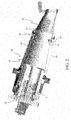
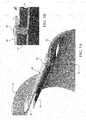
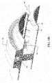
- Figures 4A to 4F are various perspective and sectional views of a second embodiment of a flow sleeve for the late lean injection of fuel through a combustor liner.
- Figures 4A and 4C are side perspective views of the second embodiment of a late lean injection flow sleeve 45, but at different points around the circumference of the flow sleeve 45, which, like the embodiment shown in Figures 3A and 3B , is used to inject a fuel/air mixture at the aft end of a liner 43, before the transition piece 24.
- Figure 4B is a partial cross-sectional view of the flow sleeve 45 and liner 43.
- Figure 4D a partial cross-sectional view of flow sleeve flange manifold
- Figures 4E and 4F are detailed partial cross-sectional views of the LLI injector.
- the late lean injection sleeve assembly shown in Figures 4A through 4F combines the traditional liner and flow sleeve assemblies into an assembly with internal fuel manifold and delivery system.
- the liner 43 and flow sleeve 45 assemblies are combined to provide a single assembly that allows for reduced leakage and improved control of potential fuel leakage.
- the late lean injection sleeve assembly shown in Figures 4A through 4F operates like the late lean injection sleeve assembly shown in Figures 3A and 3B .
- the fuel 42 required for late lean injection is supplied to the sleeve 43 via at least one ring manifold 48 in the flow sleeve flange 46.
- at least one feed hole 49 extends longitudinally through the flow sleeve 45, and the fuel 42 flows from the manifold ring 48 through these feed holes 49 to supply fuel to individual LLI nozzles/fuel injectors 40 inserted in the flow sleeve 45.
- the hole extending longitudinally through the flow sleeve is drilled through the flow sleeve, although other constructions, such as molding the holes or forming by inner and outer walls in the feed sleeve, may be used.
- each of the individual LLI nozzles/fuel injectors 40 includes a collar in which a number of small holes are formed, whereby fuel flowing from the tubes 29 in the flow sleeve 45 to flows through these holes into and through the interior of the nozzles/injectors 40 and into the combustion liner 43.
- the nozzles/injectors 40 are joined to a transfer tube 41 to transfer the fuel in the flow sleeve 45 and the air from the CDC air supply entering the nozzles/injectors 40 into the liner 43.
- the nozzles/injectors 40 and transfer tube 41 together span between the flow sleeve 45 and liner 43 assemblies, providing a central core of late lean injection without air losses and potential fuel leakages.
- the burning combustion products in the liner 23 ignite the fuel newly introduced through the nozzles/injectors 40.
- the number of nozzles/injectors 40 can be varied, depending on the fuel supply requirement.
- different types of LLI nozzles can be used in the present invention, since it is not specific to fuel nozzles.
- the late lean injection flow sleeve 45 shown in Figures 4A through 4F is preferably constructed substantially in the same manner as the late lean injection flow sleeve 25 shown in Figures 3A through 3B .
- the nozzles/injectors 40 are first fully inserted into holes in the flow sleeve 45, after which the liner 43 is inserted into the flow sleeve 45 so as to align the nozzles/injectors 40 in the flow sleeve 45 with clearance holes in the liner 43.
- the nozzles/injectors 40 are not secured by washers and bolts to the flow sleeve 45.
- the nozzles/injectors 40 and the flow sleeve 45 are provided with complimentary interlocking flanges which serve to secure the nozzles/injectors 40 to the flow sleeve 45 where they are inserted into the flow sleeve 45.
- the foregoing parts are joined together as a sub-unit so that they can be installed within the combustor 20 during assembly of the combustor, attaching on one end of the sub-assembly to the CDC.
- the assembly locates each component relative to each other axially through the fuel nozzles, such that the liner axial position is retained in the combustor via the LLI nozzles and the liner aft end radial position is held via the LLI nozzles, both these features being unique to the present invention because traditionally the liner is held axially by lugs and stops on the forward end.
- the foregoing retention arrangement allows the LLI nozzles to be in the proper position relative to the liner during all operating conditions.
- the late lean injection sleeve assembly shown in Figures 4A to 4F allows the injection of fuel/air mixture at the aft end of a gas turbine liner, before the transition piece, into the combustion gases downstream of the fuel nozzles.
- the late lean injection enables fuel injection downstream of the fuel nozzles to create a secondary/tertiary (with quaternary injection upstream of the fuel nozzles) combustion zone, while reducing/eliminating the risk of fuel leaking into the combustion discharge case.
- the fuel is delivered by the flow sleeve 45 into a nozzle 40 that mixes it with CDC air before injecting it into the liner.
- the design of the present invention allows for easy, low cost implementation of staged combustion to the aft end of the liner assembly. It is easily retrofitted into existing units and is easily installed into new units. It reduces the risk of fuel leaking into the CDC compartment by not having any non-welded interfaces.
- Figures 5A and 5B are two sectional views of a third embodiment of a late lean injection sleeve assembly for the late lean injection of fuel into a combustor liner.
- the embodiment of Figures 5A and 5B is constructed and functions substantially like the embodiments shown in Figures 3A and 3B and in Figures 4A through 4F .
- the components i.e., the liner, flow sleeve, and injectors
- the components are separate from one another.
- the components are assembled into a single component or sub-unit with an internal fuel manifold and delivery system, which is installed during assembly of the combustor.
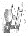
- Figures 6A and 6B are two partial perspective and sectional views of a late lean injection assembly 60 that is integrated into the combustion liner assembly 63 of a turbine combustor, so as to combine the traditional combustion liner with an integrated fuel delivery system.
- the design is a single assembly that is installed during unit assembly.
- the design has a forward flange 62 that is used for both support and to feed the fuel to the injection tubes or nozzles.
- the design can use any means of transferring fuel from a manifold flange 62 along the outside of the liner 63 to the nozzles inserted in the liner 63, like the nozzles 30 shown in Figure 2 , at the aft end of the liner 63.
- At least one conduit is used to transfer fuel from the manifold flange 62.
- the fuel is supplied to an internal manifold 64 in the forward flange 62 and is then delivered to axial running conduits in the form of tubes 64 through passages in struts 65.
- the number and orientation of the struts 65 can be varied, depending on the amount of late lean injection that is required.
- the axial running tubes 64 are supported along the length of the liner 63 by tube struts 66 that are welded to the body of liner 63. This interface is designed to minimize wear between the tube struts 66 and the tubes 61.
- the struts can be replaced with tubes that have a bend (such as a 90 degree bend) and that have fittings for attaching into the manifold 64 in flange 62.
- the integrated late lean injection assembly 60 on a combustion liner 63 provides a simple low cost option for late lean injection.
- This assembly is easily retrofitted on existing combustor units and can be installed at a lower cost than current late lean injection designs.
- the assembly 60 is a single assembly that is installed during combustor unit assembly.
- the late lean injection assembly 60 addresses the mechanical system to feed fuel to the second stage of combustion and does not address the actual injection of fuel.
- the late lean injection assembly 60 is easily retrofitted on existing units and can be installed for a fraction of the cost of current designs.
Landscapes
- Engineering & Computer Science (AREA)
- Chemical & Material Sciences (AREA)
- Combustion & Propulsion (AREA)
- Mechanical Engineering (AREA)
- General Engineering & Computer Science (AREA)
- Spray-Type Burners (AREA)
Abstract
Description
- The present invention relates to turbines, and more particularly, to integrating a late lean injection into the combustion liner of a gas turbine and to a late lean injection sleeve assembly.
- Multiple designs exist for staged combustion in gas turbines, but most are complicated assemblies consisting of a plurality of tubing and interfaces. One kind of staged combustion in gas turbines is late lean injection ("LLI") where the LLI injectors of the air/fuel mixture are located in a combustor far down stream to achieve improved NOx performance. NOx, or oxides of nitrogen, is one of the primary undesirable air polluting emissions produced by some gas turbines which burn conventional hydrocarbon fuels. The late lean injection is also used as an air bypass, which is useful to meet carbon monoxide or CO emissions during "turn down" or low load operation.
- Current late lean injection assemblies are expensive and costly for both new gas turbine units and retrofits of existing units due to the number of parts and the complexity of the fuel passages. Current late lean injection assemblies also have a high risk for fuel leakage into the compressor discharge casing, which can result in auto-ignition and be a safety hazard.
- The present invention is directed to a late lean injection sleeve assembly, which combines the traditional liner and flow sleeve assemblies into an assembly with an internal fuel manifold and an air/fuel delivery system. The liner and flow sleeve assembly allows for reduced leakage and improved control of potential fuel leakage. The fuel required for late lean injection is supplied to the sleeve via a manifold ring in the flow sleeve flange. Single feed holes are drilled through the flow sleeve. The fuel is delivered through at least one passage in the flow sleeve into nozzles or injectors that mix the fuel with compressor discharge case ("CDC") air before injecting it into the liner. Preferably, the at least one passage is one or more longitudinally extending holes or tubes in the flow sleeve, although a flow sleeve having co-annular walls could also be used to deliver the fuel to the nozzles or injectors. The number and size of nozzles/injectors can be varied, depending on the fuel supply requirement. The nozzles/injectors span both the flow sleeve and liner assemblies, providing a central core of late lean injection without air losses and potential fuel leakages.
- The delivery of fuel is preferably achieved via a combustor assembly in which the combustor's traditional flow sleeve and liner assemblies are combined into a single component with an internal fuel manifold and delivery system.
- The late lean injection sleeve assembly allows the injection of fuel at the aft end of a gas turbine liner, before the transition piece, into the combustion gases downstream of the fuel nozzles. The late lean injection enables fuel injection downstream of the fuel nozzles to create a combustion zone downstream before the turbine's transition piece, while reducing/eliminating the risk of fuel leaking into the combustion discharge case. The late lean injection sleeve assembly is easily retrofitted into existing turbine units and is easily installed into new units. It reduces the risk of fuel leaking into the CDC compartment by not having any non-welded interfaces.
- Embodiments of the present invention will now be described, by way of example only, with reference to the accompanying drawings in which:
-
Figure 1 is a simple diagram showing the components of a typical gas turbine system. -
Figure 2 is a partial side sectional view of a turbine combustor including a late lean injection system according to the present invention. -
Figures 3A and3B are a partial transparent perspective view and a side cross-sectional view, respectively, of a first embodiment of a flow sleeve for the late lean injection of fuel through a combustor liner. -
Figures 4A to 4F are various perspective and sectional views of a second embodiment of a flow sleeve for the late lean injection of fuel through a combustor liner. -
Figures 5A and 5B are two sectional views of a third embodiment of a flow sleeve for the late lean injection of fuel into a combustor liner. -
Figures 6A and6B are two partial perspective and sectional views of a late lean injection assembly that is integrated into the combustion liner assembly of a turbine combustor, so as to combine the traditional combustion liner with an integrated fuel delivery system. detailed description of the invention -
Figure 1 is a simple diagram showing the components of a typicalgas turbine system 10. Thegas turbine system 10 includes acompressor 12, which compresses incomingair 11 to high pressure, acombustor 14, which burnsfuel 13 so as to produce a high-pressure, high-velocityhot gas 17, and aturbine 16, which extracts energy from the high-pressure, high-velocityhot gas 17 entering theturbine 16 from thecombustor 14 using turbine blades (not shown), so as to be rotated by thehot gas 17. As theturbine 16 is rotated, ashaft 18 connected to theturbine 16 is caused to be rotated as well. Finally,exhaust gas 19 exits theturbine 16. -
Figure 2 is a partial side sectional view of agas turbine combustor 20 including a late lean injection system according to the present invention. The combustor 20 (combustor 14 inFigure 1 ) includes ahead end 22, which includes multiplepremixing fuel nozzles 21, and aliner 23, which is connected to thehead end 22, and in which supplied fuel is combusted. Theliner 23 defines the combustion zone of thecombustor 20. Theliner 23 is surrounded by aflow sleeve 25 and concluded by a transition piece orzone 24 connected to theliner 23. Compressor 12 (not shown inFigure 2 ) compresses inletair 11 and provides the compressed air to thecombustor 20, to thetransition piece 24, and to turbine 16 (also not shown inFigure 2 ). - As noted above, the turbine includes turbine blades, into which products of at least the combustion of the fuel in the
liner 23 are received to power a rotation of the turbine blades. The transition piece directs the flow of combustion products into theturbine 16, where they turn the blades of the turbine and generate electricity. Thus, thetransition piece 24 serves to couple thecombustor 20 and theturbine 16. But, thetransition piece 24 also includes a second combustion zone in which additional fuel supplied thereto and the products of the combustion of the fuel supplied to theliner 23 combustion zone are combusted. - As noted above, the turbine combustor shown in
Figure 2 includes a late lean injection system according to the present invention. The objectives of the late lean injection system are to locate the late lean injection system injectors far downstream for improved NOx performance of the turbine combustor, but not too far into the transition piece, so as to result in undesirable higher CO emissions. The late lean injection system of the present invention also allows the elimination of internal compressor discharge case ("CDC") piping, flexhoses, sealed connections, etc. It also provides a simple assembly for integrating late lean injection into the combustion liner of a gas turbine. -
Figure 3A is a side perspective view of one embodiment of the late leaninjection flow sleeve 25 for the injection of fuel at theaft end 33 of theliner 23, before thetransition piece 24, into the combustion gases downstream of thehead end 22 and thepremixing fuel nozzles 21. -
Figure 3A shows thatdeep holes 29 are drilled axially and longitudinally through theflow sleeve 25 to the late lean injection ("LLI") nozzles/injectors 30 located at the aft/downstream end 33 of theliner 23. Theliner 23 defines the combustion chamber where the combustion products (fuel/air mix) are burning inside theliner 23. The fuel inlet for the LLI injectors is through theflow sleeve flange 26 at the head/upstream end of thecombustor liner 23. -
Figure 3B shows a cross-sectional view of theflow sleeve 25 andliner 23. Fuel flows from at least onefuel ring manifold 28 in theflow sleeve flange 26, through the "gun drilled" long tubes/shafts/holes 29 in theflow sleeve 25, and then to the LLI nozzles/injectors 30, which are constructed like tubes connecting the (outer)flow sleeve 25 to the (inner)liner 23. There are a number ofLLI injectors 30 positioned circumferentially around theflow sleeve 25/liner 23 so that a fuel/air mixture is introduced at multiple points around theliner 23. It should be noted that a fuel/air mixture is injected into the liner because in the LLI nozzles, the fuel is injected into air that passes from the CDC cavity into the liner. This air bypasses the head end and participates in the late lean injection. Each of theLLI injectors 30 include a collar in which a number of small holes are formed. Fuel flows from thetubes 29 in theflow sleeve 25 to and through these holes into and through theinterior 30 of the tube and into thecombustion liner 23. The burning combustion products in theliner 23 ignite the newly introduced fuel/air mixture. - The late lean injection flow sleeve shown in
Figures 3A and3B is preferably constructed by first orienting theliner 23 upright, inserting theinjectors 30 fully into theliner 23, then inserting the liner into the flowsleeve (flowsleeve cannot fit over liner), aligning theinjectors 30 in theliner 23 with clearance holes inflow sleeve 25, and then installing washers and bolts to secure theinjectors 30 to theflow sleeve 25. The foregoing parts are joined together as a sub-unit so that they can be installed within thecombustor 20 during assembly of the combustor, attaching on one end of the sub-assembly to the CDC and on the downstream end, to thetransition piece 24. Thehead end 22 is then assembled onto the flowsleeve flange and inserts into the liner forward end. It should be noted the assembly locates each component relative to each other axially through the fuel nozzles. In other words, the liner axial position is retained in the combustor via the LLI nozzles and the liner aft end radial position is held via the LLI nozzles (which is unique to the present invention, since traditionally the liner is held axially by lugs and stops on the forward end). This retention allows the LLI nozzles to be in the proper position relative to the liner during all operating conditions. - Referencing
Figure 3B again, it should also be noted that theliner 23 can be a full length liner or a shortened piece that serves as a connector between a traditional liner and the transition piece. This may be used to have a more manageable assembly that can be assembled to the CDC and then the longer, traditional liner can be inserted afterwards. In this embodiment the flow sleeve/connector assembly is bolted onto the CDC and engages the transition piece, then, a traditional liner would be inserted into the connector. - As noted above,
Figures 4A to 4F are various perspective and sectional views of a second embodiment of a flow sleeve for the late lean injection of fuel through a combustor liner. Specifically,Figures 4A and4C are side perspective views of the second embodiment of a late leaninjection flow sleeve 45, but at different points around the circumference of theflow sleeve 45, which, like the embodiment shown inFigures 3A and3B , is used to inject a fuel/air mixture at the aft end of aliner 43, before thetransition piece 24.Figure 4B is a partial cross-sectional view of theflow sleeve 45 andliner 43.Figure 4D a partial cross-sectional view of flow sleeve flange manifold, whileFigures 4E and 4F are detailed partial cross-sectional views of the LLI injector. - Like the embodiment shown in
Figures 3A and3B , the late lean injection sleeve assembly shown inFigures 4A through 4F , combines the traditional liner and flow sleeve assemblies into an assembly with internal fuel manifold and delivery system. Theliner 43 and flowsleeve 45 assemblies are combined to provide a single assembly that allows for reduced leakage and improved control of potential fuel leakage. Thus, the late lean injection sleeve assembly shown inFigures 4A through 4F operates like the late lean injection sleeve assembly shown inFigures 3A and3B . - As shown in
Figures 4B and4D , thefuel 42 required for late lean injection is supplied to thesleeve 43 via at least onering manifold 48 in theflow sleeve flange 46. As shown inFigure 4B , at least onefeed hole 49 extends longitudinally through theflow sleeve 45, and thefuel 42 flows from themanifold ring 48 through these feed holes 49 to supply fuel to individual LLI nozzles/fuel injectors 40 inserted in theflow sleeve 45. Preferably, the hole extending longitudinally through the flow sleeve is drilled through the flow sleeve, although other constructions, such as molding the holes or forming by inner and outer walls in the feed sleeve, may be used. - The fuel from the feed holes 49 is mixed in the nozzles/
fuel injectors 40 with air from theCDC air supply 44 and injected into theliner 43. As can be seen in detailedFigures 4E and 4F , each of the individual LLI nozzles/fuel injectors 40 includes a collar in which a number of small holes are formed, whereby fuel flowing from thetubes 29 in theflow sleeve 45 to flows through these holes into and through the interior of the nozzles/injectors 40 and into thecombustion liner 43. As can be seen inFigures 4B ,4E and 4F , the nozzles/injectors 40 are joined to atransfer tube 41 to transfer the fuel in theflow sleeve 45 and the air from the CDC air supply entering the nozzles/injectors 40 into theliner 43. The nozzles/injectors 40 andtransfer tube 41 together span between theflow sleeve 45 andliner 43 assemblies, providing a central core of late lean injection without air losses and potential fuel leakages. The burning combustion products in theliner 23 ignite the fuel newly introduced through the nozzles/injectors 40. And, here again, the number of nozzles/injectors 40 can be varied, depending on the fuel supply requirement. Also, different types of LLI nozzles can be used in the present invention, since it is not specific to fuel nozzles. - The late lean
injection flow sleeve 45 shown inFigures 4A through 4F is preferably constructed substantially in the same manner as the late leaninjection flow sleeve 25 shown inFigures 3A through 3B . In the embodiment shown inFigures 4A through 4F , the nozzles/injectors 40 are first fully inserted into holes in theflow sleeve 45, after which theliner 43 is inserted into theflow sleeve 45 so as to align the nozzles/injectors 40 in theflow sleeve 45 with clearance holes in theliner 43. In this embodiment, the nozzles/injectors 40 are not secured by washers and bolts to theflow sleeve 45. Rather, the nozzles/injectors 40 and theflow sleeve 45 are provided with complimentary interlocking flanges which serve to secure the nozzles/injectors 40 to theflow sleeve 45 where they are inserted into theflow sleeve 45. Here again, the foregoing parts are joined together as a sub-unit so that they can be installed within thecombustor 20 during assembly of the combustor, attaching on one end of the sub-assembly to the CDC. Thehead end 22, which contains theupstream premixing nozzles 21, and on the downstream end, to thetransition piece 24. Again, thehead end 22 is then assembled onto theflow sleeve flange 46 and inserts into theliner 43 forward end. Again, it should be noted the assembly locates each component relative to each other axially through the fuel nozzles, such that the liner axial position is retained in the combustor via the LLI nozzles and the liner aft end radial position is held via the LLI nozzles, both these features being unique to the present invention because traditionally the liner is held axially by lugs and stops on the forward end. The foregoing retention arrangement allows the LLI nozzles to be in the proper position relative to the liner during all operating conditions. - Thus, the late lean injection sleeve assembly shown in
Figures 4A to 4F allows the injection of fuel/air mixture at the aft end of a gas turbine liner, before the transition piece, into the combustion gases downstream of the fuel nozzles. The late lean injection enables fuel injection downstream of the fuel nozzles to create a secondary/tertiary (with quaternary injection upstream of the fuel nozzles) combustion zone, while reducing/eliminating the risk of fuel leaking into the combustion discharge case. The fuel is delivered by theflow sleeve 45 into anozzle 40 that mixes it with CDC air before injecting it into the liner. The design of the present invention allows for easy, low cost implementation of staged combustion to the aft end of the liner assembly. It is easily retrofitted into existing units and is easily installed into new units. It reduces the risk of fuel leaking into the CDC compartment by not having any non-welded interfaces. - As noted above,
Figures 5A and 5B are two sectional views of a third embodiment of a late lean injection sleeve assembly for the late lean injection of fuel into a combustor liner. The embodiment ofFigures 5A and 5B is constructed and functions substantially like the embodiments shown inFigures 3A and3B and inFigures 4A through 4F . However, in the embodiments ofFigures 3A and3B andFigures 4A through 4F , the components (i.e., the liner, flow sleeve, and injectors) are separate from one another. In the embodiment ofFigures 5A and 5B , the components are assembled into a single component or sub-unit with an internal fuel manifold and delivery system, which is installed during assembly of the combustor. -
Figures 6A and6B are two partial perspective and sectional views of a latelean injection assembly 60 that is integrated into thecombustion liner assembly 63 of a turbine combustor, so as to combine the traditional combustion liner with an integrated fuel delivery system. The design is a single assembly that is installed during unit assembly. The design has aforward flange 62 that is used for both support and to feed the fuel to the injection tubes or nozzles. The design can use any means of transferring fuel from amanifold flange 62 along the outside of theliner 63 to the nozzles inserted in theliner 63, like thenozzles 30 shown inFigure 2 , at the aft end of theliner 63. Preferably at least one conduit is used to transfer fuel from themanifold flange 62. Preferably, the fuel is supplied to aninternal manifold 64 in theforward flange 62 and is then delivered to axial running conduits in the form oftubes 64 through passages instruts 65. The number and orientation of thestruts 65 can be varied, depending on the amount of late lean injection that is required. Theaxial running tubes 64 are supported along the length of theliner 63 by tube struts 66 that are welded to the body ofliner 63. This interface is designed to minimize wear between the tube struts 66 and thetubes 61. It should be noted that the struts can be replaced with tubes that have a bend (such as a 90 degree bend) and that have fittings for attaching into the manifold 64 inflange 62. - The integrated late
lean injection assembly 60 on acombustion liner 63 provides a simple low cost option for late lean injection. This assembly is easily retrofitted on existing combustor units and can be installed at a lower cost than current late lean injection designs. Theassembly 60 is a single assembly that is installed during combustor unit assembly. The latelean injection assembly 60 addresses the mechanical system to feed fuel to the second stage of combustion and does not address the actual injection of fuel. The latelean injection assembly 60 is easily retrofitted on existing units and can be installed for a fraction of the cost of current designs. - While the invention has been described in connection with what is presently considered to be the most practical and preferred embodiment, it is to be understood that the invention is not to be limited to the disclosed embodiment, but on the contrary, is intended to cover various modifications and equivalent arrangements included within the spirit and scope of the appended claims.
Claims (15)
- An assembly for the late lean injection of fuel (42) into a gas turbine combustor (20), the assembly comprising:a liner (23,43,53) connected between a head end (22) and a transition piece (24) of the combustor (20), the liner (23,43,53) defining a combustion zone of the combustor (20),a flow sleeve (25,45,55) surrounding the liner (23,43,53) and being concluded by the transition piece (24), the flow sleeve (25,45,55) having at least one passage (29,49,59) extending longitudinally through the flow sleeve (25,45,55),at least one nozzle (30,40,50) inserted in the flow sleeve (25,45,55) and extending to the liner (23,43,53),wherein, fuel (42) flowing through the at least one passage (29,49,59) extending longitudinally through the flow sleeve (25,45,55) is feed to the at least one nozzle (30,40,50), mixed with CDC air (44), and injected into the liner (23,43,53) for combustion therein.
- The assembly of claim 1, wherein the at least one passage (29,49,59) is a plurality of holes (29,49,59) extending longitudinally through the flow sleeve (25,45,55).
- he assembly of claim 1 or 2, wherein the flow sleeve (25,45,55) includes a flange (26,46,56) within which is at least one ring manifold (28,48) through which fuel is fed to the at least one longitudinal passage (29,49,59) in the flow sleeve (25,45,55).
- The assembly of any of claims 1 to 3, wherein each of the at least one nozzles includes a collar in which a number of small holes are formed, whereby fuel flowing from the at least one longitudinal passage (29,49,59) into the at least one nozzle flows (30,40,50) through these small holes into and through the interior of the nozzle (30,40,50), is mixed with air and injected into the combustion liner (43).
- The assembly of claim 4, wherein each of the at least one nozzles (30,40,50) is joined to a transfer tube (41) to transfer the fuel in the flow sleeve (25,45,55) and air mixed with the fuel (42) at the injector into the liner (23,43,53).
- The assembly of claim 5, wherein each of the at least one nozzles (30,40,50) and its corresponding transfer tube (41) together span between the flow sleeve (25,45,55) and the liner (23,43,53).
- The assembly of any of claims 1 to 6 comprising a plurality of nozzles (30,40,50) inserted in the flow sleeve (25,45,55) and extending to the liner (23,43,53).
- The assembly of claim 7, wherein the number of nozzles (30,40,50) inserted in the flow sleeve (25,45,55) is varied, depending on the fuel supply requirement.
- The assembly of claim 7 or 8, wherein the plurality of nozzles (30,40,50) are positioned around the circumference of the flow sleeve (25,45,55) and the liner (23,43,53).
- The assembly of any preceding claim, wherein each of the at least one nozzles (40,50) is secured to the flow sleeve (45,55) by complimentary interlocking flanges on the nozzle (40,50) and the flow sleeve (45,55).
- The assembly of any preceding claim, wherein the liner (23,43), flow sleeve (25,45), and the at least one injector (30,40) are separate components from one another.
- The assembly of any preceding claim, wherein the fuel (42) fed from the at least one longitudinal passage (29,49,59) to the at least one nozzle (30,40,50) is mixed in the nozzle (30,40,50) with air prior to injection in the liner (23,43,53).
- The assembly of any preceding claim, wherein the liner (53), flow sleeve (55), and the at least one injector (50) are assembled into a single unit, which is installed during assembly of the combustor (20).
- The assembly of any preceding claim, wherein the late lean injection by the at least one injector of fuel in the liner (23,43,53) downstream of fuel nozzles (21) in the head end (22) of the combustor creates at least a secondary combustion zone for improving the combustor's NOX performance.
- The assembly of claim 14, wherein the late lean injection by the at least one injector of fuel (42) in the liner (23,43,53) creates secondary and tertiary combustions zones in the liner (23,43,53) where the combustor includes quaternary injection upstream of the fuel nozzles (30,40,50) in the head end (22) of the combustor.
Applications Claiming Priority (1)
| Application Number | Priority Date | Filing Date | Title |
|---|---|---|---|
| US13/153,944 US8601820B2 (en) | 2011-06-06 | 2011-06-06 | Integrated late lean injection on a combustion liner and late lean injection sleeve assembly |
Publications (3)
| Publication Number | Publication Date |
|---|---|
| EP2532968A2 true EP2532968A2 (en) | 2012-12-12 |
| EP2532968A3 EP2532968A3 (en) | 2017-10-18 |
| EP2532968B1 EP2532968B1 (en) | 2018-10-10 |
Family
ID=46201468
Family Applications (1)
| Application Number | Title | Priority Date | Filing Date |
|---|---|---|---|
| EP12170621.2A Not-in-force EP2532968B1 (en) | 2011-06-06 | 2012-06-01 | Integrated late lean injection on a combustion liner and late lean injection sleeve assembly |
Country Status (3)
| Country | Link |
|---|---|
| US (1) | US8601820B2 (en) |
| EP (1) | EP2532968B1 (en) |
| CN (2) | CN102818288B (en) |
Cited By (6)
| Publication number | Priority date | Publication date | Assignee | Title |
|---|---|---|---|---|
| EP2600063A3 (en) * | 2013-02-19 | 2014-05-07 | Alstom Technology Ltd | Method of operating a gas turbine with staged and/or sequential combustion |
| WO2014110385A1 (en) * | 2013-01-11 | 2014-07-17 | Siemens Energy, Inc. | Lean-rich axial stage combustion in a can-annular gas turbine engine |
| EP2554910A3 (en) * | 2011-08-05 | 2017-11-01 | General Electric Company | Methods relating to integrating late lean injection into combustion turbine engines |
| EP2554906A3 (en) * | 2011-08-05 | 2017-11-22 | General Electric Company | Assemblies and apparatus related to integrating late lean injection into combustion turbine engines |
| US11156164B2 (en) | 2019-05-21 | 2021-10-26 | General Electric Company | System and method for high frequency accoustic dampers with caps |
| US11174792B2 (en) | 2019-05-21 | 2021-11-16 | General Electric Company | System and method for high frequency acoustic dampers with baffles |
Families Citing this family (35)
| Publication number | Priority date | Publication date | Assignee | Title |
|---|---|---|---|---|
| US9303872B2 (en) * | 2011-09-15 | 2016-04-05 | General Electric Company | Fuel injector |
| US9097424B2 (en) * | 2012-03-12 | 2015-08-04 | General Electric Company | System for supplying a fuel and working fluid mixture to a combustor |
| US9151500B2 (en) | 2012-03-15 | 2015-10-06 | General Electric Company | System for supplying a fuel and a working fluid through a liner to a combustion chamber |
| US9284888B2 (en) * | 2012-04-25 | 2016-03-15 | General Electric Company | System for supplying fuel to late-lean fuel injectors of a combustor |
| US8479518B1 (en) * | 2012-07-11 | 2013-07-09 | General Electric Company | System for supplying a working fluid to a combustor |
| US9097130B2 (en) * | 2012-09-13 | 2015-08-04 | General Electric Company | Seal for use between injector and combustion chamber in gas turbine |
| CN103925617B (en) * | 2013-01-14 | 2017-11-21 | 通用电气公司 | The stream set of turbomachinery component |
| US20140208756A1 (en) * | 2013-01-30 | 2014-07-31 | Alstom Technology Ltd. | System For Reducing Combustion Noise And Improving Cooling |
| US9322556B2 (en) | 2013-03-18 | 2016-04-26 | General Electric Company | Flow sleeve assembly for a combustion module of a gas turbine combustor |
| US10436445B2 (en) | 2013-03-18 | 2019-10-08 | General Electric Company | Assembly for controlling clearance between a liner and stationary nozzle within a gas turbine |
| US9316396B2 (en) | 2013-03-18 | 2016-04-19 | General Electric Company | Hot gas path duct for a combustor of a gas turbine |
| US9400114B2 (en) * | 2013-03-18 | 2016-07-26 | General Electric Company | Combustor support assembly for mounting a combustion module of a gas turbine |
| US9316155B2 (en) * | 2013-03-18 | 2016-04-19 | General Electric Company | System for providing fuel to a combustor |
| US9360217B2 (en) | 2013-03-18 | 2016-06-07 | General Electric Company | Flow sleeve for a combustion module of a gas turbine |
| US9631812B2 (en) | 2013-03-18 | 2017-04-25 | General Electric Company | Support frame and method for assembly of a combustion module of a gas turbine |
| US9383104B2 (en) | 2013-03-18 | 2016-07-05 | General Electric Company | Continuous combustion liner for a combustor of a gas turbine |
| US20150047360A1 (en) * | 2013-08-13 | 2015-02-19 | General Electric Company | System for injecting a liquid fuel into a combustion gas flow field |
| US20150052905A1 (en) * | 2013-08-20 | 2015-02-26 | General Electric Company | Pulse Width Modulation for Control of Late Lean Liquid Injection Velocity |
| US20150159877A1 (en) * | 2013-12-06 | 2015-06-11 | General Electric Company | Late lean injection manifold mixing system |
| US9803555B2 (en) * | 2014-04-23 | 2017-10-31 | General Electric Company | Fuel delivery system with moveably attached fuel tube |
| US9976487B2 (en) * | 2015-12-22 | 2018-05-22 | General Electric Company | Staged fuel and air injection in combustion systems of gas turbines |
| US10837644B2 (en) * | 2016-09-28 | 2020-11-17 | General Electric Company | Tool kit and method for decoupling cross-fire tube assemblies in gas turbine engines |
| US10843277B2 (en) * | 2017-01-16 | 2020-11-24 | General Electric Company | Portable jig and fixture for precision machining |
| US20180340689A1 (en) * | 2017-05-25 | 2018-11-29 | General Electric Company | Low Profile Axially Staged Fuel Injector |
| KR101954535B1 (en) | 2017-10-31 | 2019-03-05 | 두산중공업 주식회사 | Combustor and gas turbine including the same |
| US10982856B2 (en) * | 2019-02-01 | 2021-04-20 | Pratt & Whitney Canada Corp. | Fuel nozzle with sleeves for thermal protection |
| US11371709B2 (en) | 2020-06-30 | 2022-06-28 | General Electric Company | Combustor air flow path |
| US11435080B1 (en) | 2021-06-17 | 2022-09-06 | General Electric Company | Combustor having fuel sweeping structures |
| US12044411B2 (en) | 2021-06-17 | 2024-07-23 | Ge Infrastructure Technology Llc | Combustor having fuel sweeping structures |
| US12270543B2 (en) * | 2021-08-20 | 2025-04-08 | Rtx Corporation | Multi-function monolithic combustion liner |
| US11898753B2 (en) | 2021-10-11 | 2024-02-13 | Ge Infrastructure Technology Llc | System and method for sweeping leaked fuel in gas turbine system |
| US11808455B2 (en) * | 2021-11-24 | 2023-11-07 | Rtx Corporation | Gas turbine engine combustor with integral fuel conduit(s) |
| US11578871B1 (en) * | 2022-01-28 | 2023-02-14 | General Electric Company | Gas turbine engine combustor with primary and secondary fuel injectors |
| US11846249B1 (en) | 2022-09-02 | 2023-12-19 | Rtx Corporation | Gas turbine engine with integral bypass duct |
| US12601483B2 (en) * | 2023-12-29 | 2026-04-14 | Ge Infrastructure Technology Llc | Additively manufactured combustion liner and axial fuel stage injector |
Family Cites Families (92)
| Publication number | Priority date | Publication date | Assignee | Title |
|---|---|---|---|---|
| GB854135A (en) | 1958-03-05 | 1960-11-16 | Rolls Royce | Improvements in or relating to combustion equipment |
| US3099134A (en) | 1959-12-24 | 1963-07-30 | Havilland Engine Co Ltd | Combustion chambers |
| US3924576A (en) | 1972-05-12 | 1975-12-09 | Gen Motors Corp | Staged combustion engines and methods of operation |
| US4614082A (en) * | 1972-12-19 | 1986-09-30 | General Electric Company | Combustion chamber construction |
| FR2221621B1 (en) | 1973-03-13 | 1976-09-10 | Snecma | |
| US3872664A (en) | 1973-10-15 | 1975-03-25 | United Aircraft Corp | Swirl combustor with vortex burning and mixing |
| US4028888A (en) | 1974-05-03 | 1977-06-14 | Norwalk-Turbo Inc. | Fuel distribution manifold to an annular combustion chamber |
| US4271674A (en) | 1974-10-17 | 1981-06-09 | United Technologies Corporation | Premix combustor assembly |
| DE2629761A1 (en) | 1976-07-02 | 1978-01-05 | Volkswagenwerk Ag | COMBUSTION CHAMBER FOR GAS TURBINES |
| US4236378A (en) | 1978-03-01 | 1980-12-02 | General Electric Company | Sectoral combustor for burning low-BTU fuel gas |
| US4265615A (en) | 1978-12-11 | 1981-05-05 | United Technologies Corporation | Fuel injection system for low emission burners |
| US4420929A (en) | 1979-01-12 | 1983-12-20 | General Electric Company | Dual stage-dual mode low emission gas turbine combustion system |
| US4590769A (en) | 1981-01-12 | 1986-05-27 | United Technologies Corporation | High-performance burner construction |
| US4543894A (en) | 1983-05-17 | 1985-10-01 | Union Oil Company Of California | Process for staged combustion of retorted oil shale |
| JPS6057131A (en) | 1983-09-08 | 1985-04-02 | Hitachi Ltd | Fuel feeding process for gas turbine combustor |
| JPH0752014B2 (en) | 1986-03-20 | 1995-06-05 | 株式会社日立製作所 | Gas turbine combustor |
| JPH01114623A (en) | 1987-10-27 | 1989-05-08 | Toshiba Corp | Gas turbine combustor |
| US4928481A (en) | 1988-07-13 | 1990-05-29 | Prutech Ii | Staged low NOx premix gas turbine combustor |
| JPH0684817B2 (en) | 1988-08-08 | 1994-10-26 | 株式会社日立製作所 | Gas turbine combustor and operating method thereof |
| US4989549A (en) | 1988-10-11 | 1991-02-05 | Donlee Technologies, Inc. | Ultra-low NOx combustion apparatus |
| US4998410A (en) | 1989-09-05 | 1991-03-12 | Rockwell International Corporation | Hybrid staged combustion-expander topping cycle engine |
| US5749219A (en) * | 1989-11-30 | 1998-05-12 | United Technologies Corporation | Combustor with first and second zones |
| US5099644A (en) | 1990-04-04 | 1992-03-31 | General Electric Company | Lean staged combustion assembly |
| US5076229A (en) | 1990-10-04 | 1991-12-31 | Stanley Russel S | Internal combustion engines and method of operting an internal combustion engine using staged combustion |
| KR930013441A (en) * | 1991-12-18 | 1993-07-21 | 아더 엠.킹 | Gas turbine combustor with multiple combustors |
| US5259184A (en) | 1992-03-30 | 1993-11-09 | General Electric Company | Dry low NOx single stage dual mode combustor construction for a gas turbine |
| US5274991A (en) | 1992-03-30 | 1994-01-04 | General Electric Company | Dry low NOx multi-nozzle combustion liner cap assembly |
| US5518395A (en) | 1993-04-30 | 1996-05-21 | General Electric Company | Entrainment fuel nozzle for partial premixing of gaseous fuel and air to reduce emissions |
| GB2278431A (en) | 1993-05-24 | 1994-11-30 | Rolls Royce Plc | A gas turbine engine combustion chamber |
| JP3335713B2 (en) | 1993-06-28 | 2002-10-21 | 株式会社東芝 | Gas turbine combustor |
| US5377483A (en) | 1993-07-07 | 1995-01-03 | Mowill; R. Jan | Process for single stage premixed constant fuel/air ratio combustion |
| US5638674A (en) | 1993-07-07 | 1997-06-17 | Mowill; R. Jan | Convectively cooled, single stage, fully premixed controllable fuel/air combustor with tangential admission |
| US5350293A (en) | 1993-07-20 | 1994-09-27 | Institute Of Gas Technology | Method for two-stage combustion utilizing forced internal recirculation |
| US5323600A (en) | 1993-08-03 | 1994-06-28 | General Electric Company | Liner stop assembly for a combustor |
| US5394688A (en) | 1993-10-27 | 1995-03-07 | Westinghouse Electric Corporation | Gas turbine combustor swirl vane arrangement |
| US5408825A (en) | 1993-12-03 | 1995-04-25 | Westinghouse Electric Corporation | Dual fuel gas turbine combustor |
| US5749218A (en) | 1993-12-17 | 1998-05-12 | General Electric Co. | Wear reduction kit for gas turbine combustors |
| JP2950720B2 (en) | 1994-02-24 | 1999-09-20 | 株式会社東芝 | Gas turbine combustion device and combustion control method therefor |
| AU681271B2 (en) | 1994-06-07 | 1997-08-21 | Westinghouse Electric Corporation | Method and apparatus for sequentially staged combustion using a catalyst |
| US6182451B1 (en) | 1994-09-14 | 2001-02-06 | Alliedsignal Inc. | Gas turbine combustor waving ceramic combustor cans and an annular metallic combustor |
| US5657632A (en) | 1994-11-10 | 1997-08-19 | Westinghouse Electric Corporation | Dual fuel gas turbine combustor |
| JP3502171B2 (en) | 1994-12-05 | 2004-03-02 | 株式会社日立製作所 | Gas turbine control method |
| US5687571A (en) | 1995-02-20 | 1997-11-18 | Asea Brown Boveri Ag | Combustion chamber with two-stage combustion |
| DE19510744A1 (en) | 1995-03-24 | 1996-09-26 | Abb Management Ag | Combustion chamber with two-stage combustion |
| US5647215A (en) | 1995-11-07 | 1997-07-15 | Westinghouse Electric Corporation | Gas turbine combustor with turbulence enhanced mixing fuel injectors |
| US5826429A (en) | 1995-12-22 | 1998-10-27 | General Electric Co. | Catalytic combustor with lean direct injection of gas fuel for low emissions combustion and methods of operation |
| US6047550A (en) | 1996-05-02 | 2000-04-11 | General Electric Co. | Premixing dry low NOx emissions combustor with lean direct injection of gas fuel |
| US20010049932A1 (en) | 1996-05-02 | 2001-12-13 | Beebe Kenneth W. | Premixing dry low NOx emissions combustor with lean direct injection of gas fuel |
| US6092363A (en) | 1998-06-19 | 2000-07-25 | Siemens Westinghouse Power Corporation | Low Nox combustor having dual fuel injection system |
| US6343462B1 (en) | 1998-11-13 | 2002-02-05 | Praxair Technology, Inc. | Gas turbine power augmentation by the addition of nitrogen and moisture to the fuel gas |
| US6705117B2 (en) | 1999-08-16 | 2004-03-16 | The Boc Group, Inc. | Method of heating a glass melting furnace using a roof mounted, staged combustion oxygen-fuel burner |
| GB0019533D0 (en) | 2000-08-10 | 2000-09-27 | Rolls Royce Plc | A combustion chamber |
| US6289851B1 (en) | 2000-10-18 | 2001-09-18 | Institute Of Gas Technology | Compact low-nox high-efficiency heating apparatus |
| JP3945152B2 (en) | 2000-11-21 | 2007-07-18 | 日産自動車株式会社 | Combustion control device for internal combustion engine |
| DE10104150A1 (en) | 2001-01-30 | 2002-09-05 | Alstom Switzerland Ltd | Burner system and method for its operation |
| US6620457B2 (en) | 2001-07-13 | 2003-09-16 | General Electric Company | Method for thermal barrier coating and a liner made using said method |
| US20030024234A1 (en) | 2001-08-02 | 2003-02-06 | Siemens Westinghouse Power Corporation | Secondary combustor for low NOx gas combustion turbine |
| US6663380B2 (en) | 2001-09-05 | 2003-12-16 | Gas Technology Institute | Method and apparatus for advanced staged combustion utilizing forced internal recirculation |
| US6775987B2 (en) | 2002-09-12 | 2004-08-17 | The Boeing Company | Low-emission, staged-combustion power generation |
| US7040094B2 (en) | 2002-09-20 | 2006-05-09 | The Regents Of The University Of California | Staged combustion with piston engine and turbine engine supercharger |
| US6868676B1 (en) | 2002-12-20 | 2005-03-22 | General Electric Company | Turbine containing system and an injector therefor |
| US7149632B1 (en) | 2003-03-10 | 2006-12-12 | General Electric Company | On-line system and method for processing information relating to the wear of turbine components |
| US7082770B2 (en) | 2003-12-24 | 2006-08-01 | Martling Vincent C | Flow sleeve for a low NOx combustor |
| US7302801B2 (en) | 2004-04-19 | 2007-12-04 | Hamilton Sundstrand Corporation | Lean-staged pyrospin combustor |
| US7185497B2 (en) | 2004-05-04 | 2007-03-06 | Honeywell International, Inc. | Rich quick mix combustion system |
| US7303388B2 (en) | 2004-07-01 | 2007-12-04 | Air Products And Chemicals, Inc. | Staged combustion system with ignition-assisted fuel lances |
| US7574865B2 (en) * | 2004-11-18 | 2009-08-18 | Siemens Energy, Inc. | Combustor flow sleeve with optimized cooling and airflow distribution |
| US7568343B2 (en) | 2005-09-12 | 2009-08-04 | Florida Turbine Technologies, Inc. | Small gas turbine engine with multiple burn zones |
| US7685823B2 (en) | 2005-10-28 | 2010-03-30 | Power Systems Mfg., Llc | Airflow distribution to a low emissions combustor |
| US7878000B2 (en) * | 2005-12-20 | 2011-02-01 | General Electric Company | Pilot fuel injector for mixer assembly of a high pressure gas turbine engine |
| US8028529B2 (en) * | 2006-05-04 | 2011-10-04 | General Electric Company | Low emissions gas turbine combustor |
| US8033113B2 (en) * | 2006-08-31 | 2011-10-11 | Pratt & Whitney Canada Corp. | Fuel injection system for a gas turbine engine |
| US7926286B2 (en) | 2006-09-26 | 2011-04-19 | Pratt & Whitney Canada Corp. | Heat shield for a fuel manifold |
| JP2008261605A (en) * | 2007-04-13 | 2008-10-30 | Mitsubishi Heavy Ind Ltd | Gas turbine combustor |
| US7886545B2 (en) | 2007-04-27 | 2011-02-15 | General Electric Company | Methods and systems to facilitate reducing NOx emissions in combustion systems |
| US7966820B2 (en) * | 2007-08-15 | 2011-06-28 | General Electric Company | Method and apparatus for combusting fuel within a gas turbine engine |
| US8387398B2 (en) | 2007-09-14 | 2013-03-05 | Siemens Energy, Inc. | Apparatus and method for controlling the secondary injection of fuel |
| US7757491B2 (en) | 2008-05-09 | 2010-07-20 | General Electric Company | Fuel nozzle for a gas turbine engine and method for fabricating the same |
| US8528340B2 (en) * | 2008-07-28 | 2013-09-10 | Siemens Energy, Inc. | Turbine engine flow sleeve |
| US8516820B2 (en) * | 2008-07-28 | 2013-08-27 | Siemens Energy, Inc. | Integral flow sleeve and fuel injector assembly |
| US20100024425A1 (en) * | 2008-07-31 | 2010-02-04 | General Electric Company | Turbine engine fuel nozzle |
| US20100071377A1 (en) * | 2008-09-19 | 2010-03-25 | Fox Timothy A | Combustor Apparatus for Use in a Gas Turbine Engine |
| US8375726B2 (en) * | 2008-09-24 | 2013-02-19 | Siemens Energy, Inc. | Combustor assembly in a gas turbine engine |
| US8701382B2 (en) | 2009-01-07 | 2014-04-22 | General Electric Company | Late lean injection with expanded fuel flexibility |
| US8701418B2 (en) | 2009-01-07 | 2014-04-22 | General Electric Company | Late lean injection for fuel flexibility |
| US8701383B2 (en) * | 2009-01-07 | 2014-04-22 | General Electric Company | Late lean injection system configuration |
| US8112216B2 (en) | 2009-01-07 | 2012-02-07 | General Electric Company | Late lean injection with adjustable air splits |
| US8683808B2 (en) | 2009-01-07 | 2014-04-01 | General Electric Company | Late lean injection control strategy |
| US8707707B2 (en) | 2009-01-07 | 2014-04-29 | General Electric Company | Late lean injection fuel staging configurations |
| US8307657B2 (en) * | 2009-03-10 | 2012-11-13 | General Electric Company | Combustor liner cooling system |
| US20100326079A1 (en) * | 2009-06-25 | 2010-12-30 | Baifang Zuo | Method and system to reduce vane swirl angle in a gas turbine engine |
| US8991192B2 (en) * | 2009-09-24 | 2015-03-31 | Siemens Energy, Inc. | Fuel nozzle assembly for use as structural support for a duct structure in a combustor of a gas turbine engine |
-
2011
- 2011-06-06 US US13/153,944 patent/US8601820B2/en not_active Expired - Fee Related
-
2012
- 2012-06-01 EP EP12170621.2A patent/EP2532968B1/en not_active Not-in-force
- 2012-06-06 CN CN201210183968.3A patent/CN102818288B/en not_active Expired - Fee Related
- 2012-06-06 CN CN201510886901.XA patent/CN105299694B/en not_active Expired - Fee Related
Non-Patent Citations (1)
| Title |
|---|
| None |
Cited By (9)
| Publication number | Priority date | Publication date | Assignee | Title |
|---|---|---|---|---|
| EP2554910A3 (en) * | 2011-08-05 | 2017-11-01 | General Electric Company | Methods relating to integrating late lean injection into combustion turbine engines |
| EP2554906A3 (en) * | 2011-08-05 | 2017-11-22 | General Electric Company | Assemblies and apparatus related to integrating late lean injection into combustion turbine engines |
| WO2014110385A1 (en) * | 2013-01-11 | 2014-07-17 | Siemens Energy, Inc. | Lean-rich axial stage combustion in a can-annular gas turbine engine |
| US9366443B2 (en) | 2013-01-11 | 2016-06-14 | Siemens Energy, Inc. | Lean-rich axial stage combustion in a can-annular gas turbine engine |
| EP2600063A3 (en) * | 2013-02-19 | 2014-05-07 | Alstom Technology Ltd | Method of operating a gas turbine with staged and/or sequential combustion |
| WO2014128146A1 (en) * | 2013-02-19 | 2014-08-28 | Alstom Technology Ltd | Method of operating a gas turbine with staged and/or sequential combustion |
| RU2665773C2 (en) * | 2013-02-19 | 2018-09-04 | АНСАЛДО ЭНЕРДЖИА АйПи ЮКей ЛИМИТЕД | Gas turbine plant operation method with step and / or sequential combustion |
| US11156164B2 (en) | 2019-05-21 | 2021-10-26 | General Electric Company | System and method for high frequency accoustic dampers with caps |
| US11174792B2 (en) | 2019-05-21 | 2021-11-16 | General Electric Company | System and method for high frequency acoustic dampers with baffles |
Also Published As
| Publication number | Publication date |
|---|---|
| CN105299694A (en) | 2016-02-03 |
| US20120304648A1 (en) | 2012-12-06 |
| US8601820B2 (en) | 2013-12-10 |
| EP2532968B1 (en) | 2018-10-10 |
| CN102818288B (en) | 2016-01-13 |
| CN102818288A (en) | 2012-12-12 |
| CN105299694B (en) | 2018-05-22 |
| EP2532968A3 (en) | 2017-10-18 |
Similar Documents
| Publication | Publication Date | Title |
|---|---|---|
| EP2532968B1 (en) | Integrated late lean injection on a combustion liner and late lean injection sleeve assembly | |
| US9010120B2 (en) | Assemblies and apparatus related to integrating late lean injection into combustion turbine engines | |
| US8919137B2 (en) | Assemblies and apparatus related to integrating late lean injection into combustion turbine engines | |
| US8407892B2 (en) | Methods relating to integrating late lean injection into combustion turbine engines | |
| CN103822228B (en) | Fuel nozzle and its assemble method | |
| EP1106928A1 (en) | Fuel system configuration and method for staging fuel for gas turbines utilizing both gaseous and liquid fuels | |
| CN101446211B (en) | Gas turbine fuel injector with insulating air shroud | |
| EP3341656B1 (en) | Fuel nozzle assembly for a gas turbine | |
| TW201030228A (en) | Combustor nozzle | |
| CN109073227A (en) | Fuel injector and classification fuel conveying method for internal combustion engine | |
| CN104748151A (en) | Late lean injection manifold mixing system | |
| CN108474557B (en) | Fuel injector with dual main fuel injection | |
| JP2017110902A (en) | Slot-type injector for multistage fuel in the axial direction | |
| CN101839480A (en) | Burner assembly that uses in the gas-turbine unit and assemble method thereof | |
| RU2657075C2 (en) | Shrouded pilot liquid tube | |
| CN112334706B (en) | Fuel injector with centerbody assembly | |
| US20110072823A1 (en) | Gas turbine engine fuel injector | |
| CN110030581B (en) | Burners for gas turbine power station burners | |
| JP2019049254A (en) | Dual fuel fuel nozzle with gas fuel and liquid fuel functions |
Legal Events
| Date | Code | Title | Description |
|---|---|---|---|
| PUAI | Public reference made under article 153(3) epc to a published international application that has entered the european phase |
Free format text: ORIGINAL CODE: 0009012 |
|
| AK | Designated contracting states |
Kind code of ref document: A2 Designated state(s): AL AT BE BG CH CY CZ DE DK EE ES FI FR GB GR HR HU IE IS IT LI LT LU LV MC MK MT NL NO PL PT RO RS SE SI SK SM TR |
|
| AX | Request for extension of the european patent |
Extension state: BA ME |
|
| PUAL | Search report despatched |
Free format text: ORIGINAL CODE: 0009013 |
|
| AK | Designated contracting states |
Kind code of ref document: A3 Designated state(s): AL AT BE BG CH CY CZ DE DK EE ES FI FR GB GR HR HU IE IS IT LI LT LU LV MC MK MT NL NO PL PT RO RS SE SI SK SM TR |
|
| AX | Request for extension of the european patent |
Extension state: BA ME |
|
| RIC1 | Information provided on ipc code assigned before grant |
Ipc: F23R 3/28 20060101ALI20170912BHEP Ipc: F23R 3/34 20060101AFI20170912BHEP Ipc: F23R 3/06 20060101ALI20170912BHEP |
|
| STAA | Information on the status of an ep patent application or granted ep patent |
Free format text: STATUS: REQUEST FOR EXAMINATION WAS MADE |
|
| 17P | Request for examination filed |
Effective date: 20180418 |
|
| RBV | Designated contracting states (corrected) |
Designated state(s): AL AT BE BG CH CY CZ DE DK EE ES FI FR GB GR HR HU IE IS IT LI LT LU LV MC MK MT NL NO PL PT RO RS SE SI SK SM TR |
|
| GRAP | Despatch of communication of intention to grant a patent |
Free format text: ORIGINAL CODE: EPIDOSNIGR1 |
|
| STAA | Information on the status of an ep patent application or granted ep patent |
Free format text: STATUS: GRANT OF PATENT IS INTENDED |
|
| INTG | Intention to grant announced |
Effective date: 20180601 |
|
| GRAS | Grant fee paid |
Free format text: ORIGINAL CODE: EPIDOSNIGR3 |
|
| GRAA | (expected) grant |
Free format text: ORIGINAL CODE: 0009210 |
|
| STAA | Information on the status of an ep patent application or granted ep patent |
Free format text: STATUS: THE PATENT HAS BEEN GRANTED |
|
| AK | Designated contracting states |
Kind code of ref document: B1 Designated state(s): AL AT BE BG CH CY CZ DE DK EE ES FI FR GB GR HR HU IE IS IT LI LT LU LV MC MK MT NL NO PL PT RO RS SE SI SK SM TR |
|
| REG | Reference to a national code |
Ref country code: GB Ref legal event code: FG4D |
|
| REG | Reference to a national code |
Ref country code: CH Ref legal event code: EP Ref country code: AT Ref legal event code: REF Ref document number: 1051690 Country of ref document: AT Kind code of ref document: T Effective date: 20181015 |
|
| REG | Reference to a national code |
Ref country code: IE Ref legal event code: FG4D |
|
| REG | Reference to a national code |
Ref country code: DE Ref legal event code: R096 Ref document number: 602012051962 Country of ref document: DE |
|
| REG | Reference to a national code |
Ref country code: NL Ref legal event code: MP Effective date: 20181010 |
|
| REG | Reference to a national code |
Ref country code: LT Ref legal event code: MG4D |
|
| REG | Reference to a national code |
Ref country code: AT Ref legal event code: MK05 Ref document number: 1051690 Country of ref document: AT Kind code of ref document: T Effective date: 20181010 |
|
| PG25 | Lapsed in a contracting state [announced via postgrant information from national office to epo] |
Ref country code: NL Free format text: LAPSE BECAUSE OF FAILURE TO SUBMIT A TRANSLATION OF THE DESCRIPTION OR TO PAY THE FEE WITHIN THE PRESCRIBED TIME-LIMIT Effective date: 20181010 |
|
| PG25 | Lapsed in a contracting state [announced via postgrant information from national office to epo] |
Ref country code: FI Free format text: LAPSE BECAUSE OF FAILURE TO SUBMIT A TRANSLATION OF THE DESCRIPTION OR TO PAY THE FEE WITHIN THE PRESCRIBED TIME-LIMIT Effective date: 20181010 Ref country code: NO Free format text: LAPSE BECAUSE OF FAILURE TO SUBMIT A TRANSLATION OF THE DESCRIPTION OR TO PAY THE FEE WITHIN THE PRESCRIBED TIME-LIMIT Effective date: 20190110 Ref country code: IS Free format text: LAPSE BECAUSE OF FAILURE TO SUBMIT A TRANSLATION OF THE DESCRIPTION OR TO PAY THE FEE WITHIN THE PRESCRIBED TIME-LIMIT Effective date: 20190210 Ref country code: HR Free format text: LAPSE BECAUSE OF FAILURE TO SUBMIT A TRANSLATION OF THE DESCRIPTION OR TO PAY THE FEE WITHIN THE PRESCRIBED TIME-LIMIT Effective date: 20181010 Ref country code: PL Free format text: LAPSE BECAUSE OF FAILURE TO SUBMIT A TRANSLATION OF THE DESCRIPTION OR TO PAY THE FEE WITHIN THE PRESCRIBED TIME-LIMIT Effective date: 20181010 Ref country code: LT Free format text: LAPSE BECAUSE OF FAILURE TO SUBMIT A TRANSLATION OF THE DESCRIPTION OR TO PAY THE FEE WITHIN THE PRESCRIBED TIME-LIMIT Effective date: 20181010 Ref country code: BG Free format text: LAPSE BECAUSE OF FAILURE TO SUBMIT A TRANSLATION OF THE DESCRIPTION OR TO PAY THE FEE WITHIN THE PRESCRIBED TIME-LIMIT Effective date: 20190110 Ref country code: ES Free format text: LAPSE BECAUSE OF FAILURE TO SUBMIT A TRANSLATION OF THE DESCRIPTION OR TO PAY THE FEE WITHIN THE PRESCRIBED TIME-LIMIT Effective date: 20181010 Ref country code: LV Free format text: LAPSE BECAUSE OF FAILURE TO SUBMIT A TRANSLATION OF THE DESCRIPTION OR TO PAY THE FEE WITHIN THE PRESCRIBED TIME-LIMIT Effective date: 20181010 Ref country code: AT Free format text: LAPSE BECAUSE OF FAILURE TO SUBMIT A TRANSLATION OF THE DESCRIPTION OR TO PAY THE FEE WITHIN THE PRESCRIBED TIME-LIMIT Effective date: 20181010 |
|
| PG25 | Lapsed in a contracting state [announced via postgrant information from national office to epo] |
Ref country code: PT Free format text: LAPSE BECAUSE OF FAILURE TO SUBMIT A TRANSLATION OF THE DESCRIPTION OR TO PAY THE FEE WITHIN THE PRESCRIBED TIME-LIMIT Effective date: 20190210 Ref country code: AL Free format text: LAPSE BECAUSE OF FAILURE TO SUBMIT A TRANSLATION OF THE DESCRIPTION OR TO PAY THE FEE WITHIN THE PRESCRIBED TIME-LIMIT Effective date: 20181010 Ref country code: RS Free format text: LAPSE BECAUSE OF FAILURE TO SUBMIT A TRANSLATION OF THE DESCRIPTION OR TO PAY THE FEE WITHIN THE PRESCRIBED TIME-LIMIT Effective date: 20181010 Ref country code: GR Free format text: LAPSE BECAUSE OF FAILURE TO SUBMIT A TRANSLATION OF THE DESCRIPTION OR TO PAY THE FEE WITHIN THE PRESCRIBED TIME-LIMIT Effective date: 20190111 Ref country code: SE Free format text: LAPSE BECAUSE OF FAILURE TO SUBMIT A TRANSLATION OF THE DESCRIPTION OR TO PAY THE FEE WITHIN THE PRESCRIBED TIME-LIMIT Effective date: 20181010 |
|
| REG | Reference to a national code |
Ref country code: DE Ref legal event code: R097 Ref document number: 602012051962 Country of ref document: DE |
|
| PG25 | Lapsed in a contracting state [announced via postgrant information from national office to epo] |
Ref country code: DK Free format text: LAPSE BECAUSE OF FAILURE TO SUBMIT A TRANSLATION OF THE DESCRIPTION OR TO PAY THE FEE WITHIN THE PRESCRIBED TIME-LIMIT Effective date: 20181010 Ref country code: CZ Free format text: LAPSE BECAUSE OF FAILURE TO SUBMIT A TRANSLATION OF THE DESCRIPTION OR TO PAY THE FEE WITHIN THE PRESCRIBED TIME-LIMIT Effective date: 20181010 |
|
| PGFP | Annual fee paid to national office [announced via postgrant information from national office to epo] |
Ref country code: IT Payment date: 20190419 Year of fee payment: 14 |
|
| PLBE | No opposition filed within time limit |
Free format text: ORIGINAL CODE: 0009261 |
|
| STAA | Information on the status of an ep patent application or granted ep patent |
Free format text: STATUS: NO OPPOSITION FILED WITHIN TIME LIMIT |
|
| PG25 | Lapsed in a contracting state [announced via postgrant information from national office to epo] |
Ref country code: SK Free format text: LAPSE BECAUSE OF FAILURE TO SUBMIT A TRANSLATION OF THE DESCRIPTION OR TO PAY THE FEE WITHIN THE PRESCRIBED TIME-LIMIT Effective date: 20181010 Ref country code: RO Free format text: LAPSE BECAUSE OF FAILURE TO SUBMIT A TRANSLATION OF THE DESCRIPTION OR TO PAY THE FEE WITHIN THE PRESCRIBED TIME-LIMIT Effective date: 20181010 Ref country code: EE Free format text: LAPSE BECAUSE OF FAILURE TO SUBMIT A TRANSLATION OF THE DESCRIPTION OR TO PAY THE FEE WITHIN THE PRESCRIBED TIME-LIMIT Effective date: 20181010 Ref country code: SM Free format text: LAPSE BECAUSE OF FAILURE TO SUBMIT A TRANSLATION OF THE DESCRIPTION OR TO PAY THE FEE WITHIN THE PRESCRIBED TIME-LIMIT Effective date: 20181010 |
|
| 26N | No opposition filed |
Effective date: 20190711 |
|
| PG25 | Lapsed in a contracting state [announced via postgrant information from national office to epo] |
Ref country code: SI Free format text: LAPSE BECAUSE OF FAILURE TO SUBMIT A TRANSLATION OF THE DESCRIPTION OR TO PAY THE FEE WITHIN THE PRESCRIBED TIME-LIMIT Effective date: 20181010 |
|
| PG25 | Lapsed in a contracting state [announced via postgrant information from national office to epo] |
Ref country code: MC Free format text: LAPSE BECAUSE OF FAILURE TO SUBMIT A TRANSLATION OF THE DESCRIPTION OR TO PAY THE FEE WITHIN THE PRESCRIBED TIME-LIMIT Effective date: 20181010 |
|
| REG | Reference to a national code |
Ref country code: CH Ref legal event code: PL |
|
| GBPC | Gb: european patent ceased through non-payment of renewal fee |
Effective date: 20190601 |
|
| REG | Reference to a national code |
Ref country code: BE Ref legal event code: MM Effective date: 20190630 |
|
| PG25 | Lapsed in a contracting state [announced via postgrant information from national office to epo] |
Ref country code: TR Free format text: LAPSE BECAUSE OF FAILURE TO SUBMIT A TRANSLATION OF THE DESCRIPTION OR TO PAY THE FEE WITHIN THE PRESCRIBED TIME-LIMIT Effective date: 20181010 |
|
| PG25 | Lapsed in a contracting state [announced via postgrant information from national office to epo] |
Ref country code: GB Free format text: LAPSE BECAUSE OF NON-PAYMENT OF DUE FEES Effective date: 20190601 Ref country code: IE Free format text: LAPSE BECAUSE OF NON-PAYMENT OF DUE FEES Effective date: 20190601 |
|
| PG25 | Lapsed in a contracting state [announced via postgrant information from national office to epo] |
Ref country code: BE Free format text: LAPSE BECAUSE OF NON-PAYMENT OF DUE FEES Effective date: 20190630 Ref country code: CH Free format text: LAPSE BECAUSE OF NON-PAYMENT OF DUE FEES Effective date: 20190630 Ref country code: LI Free format text: LAPSE BECAUSE OF NON-PAYMENT OF DUE FEES Effective date: 20190630 Ref country code: LU Free format text: LAPSE BECAUSE OF NON-PAYMENT OF DUE FEES Effective date: 20190601 |
|
| PG25 | Lapsed in a contracting state [announced via postgrant information from national office to epo] |
Ref country code: FR Free format text: LAPSE BECAUSE OF NON-PAYMENT OF DUE FEES Effective date: 20190630 |
|
| PGFP | Annual fee paid to national office [announced via postgrant information from national office to epo] |
Ref country code: DE Payment date: 20200519 Year of fee payment: 9 |
|
| PG25 | Lapsed in a contracting state [announced via postgrant information from national office to epo] |
Ref country code: CY Free format text: LAPSE BECAUSE OF FAILURE TO SUBMIT A TRANSLATION OF THE DESCRIPTION OR TO PAY THE FEE WITHIN THE PRESCRIBED TIME-LIMIT Effective date: 20181010 |
|
| PG25 | Lapsed in a contracting state [announced via postgrant information from national office to epo] |
Ref country code: HU Free format text: LAPSE BECAUSE OF FAILURE TO SUBMIT A TRANSLATION OF THE DESCRIPTION OR TO PAY THE FEE WITHIN THE PRESCRIBED TIME-LIMIT; INVALID AB INITIO Effective date: 20120601 Ref country code: MT Free format text: LAPSE BECAUSE OF FAILURE TO SUBMIT A TRANSLATION OF THE DESCRIPTION OR TO PAY THE FEE WITHIN THE PRESCRIBED TIME-LIMIT Effective date: 20181010 |
|
| PG25 | Lapsed in a contracting state [announced via postgrant information from national office to epo] |
Ref country code: IT Free format text: LAPSE BECAUSE OF NON-PAYMENT OF DUE FEES Effective date: 20200601 |
|
| REG | Reference to a national code |
Ref country code: DE Ref legal event code: R119 Ref document number: 602012051962 Country of ref document: DE |
|
| PG25 | Lapsed in a contracting state [announced via postgrant information from national office to epo] |
Ref country code: DE Free format text: LAPSE BECAUSE OF NON-PAYMENT OF DUE FEES Effective date: 20220101 |
|
| PG25 | Lapsed in a contracting state [announced via postgrant information from national office to epo] |
Ref country code: MK Free format text: LAPSE BECAUSE OF FAILURE TO SUBMIT A TRANSLATION OF THE DESCRIPTION OR TO PAY THE FEE WITHIN THE PRESCRIBED TIME-LIMIT Effective date: 20181010 |