EP2532967A2 - Combustor nozzle and method for modifying the combustor nozzle - Google Patents
Combustor nozzle and method for modifying the combustor nozzle Download PDFInfo
- Publication number
- EP2532967A2 EP2532967A2 EP12171076A EP12171076A EP2532967A2 EP 2532967 A2 EP2532967 A2 EP 2532967A2 EP 12171076 A EP12171076 A EP 12171076A EP 12171076 A EP12171076 A EP 12171076A EP 2532967 A2 EP2532967 A2 EP 2532967A2
- Authority
- EP
- European Patent Office
- Prior art keywords
- passages
- slit
- nozzle
- downstream
- combustor nozzle
- Prior art date
- Legal status (The legal status is an assumption and is not a legal conclusion. Google has not performed a legal analysis and makes no representation as to the accuracy of the status listed.)
- Withdrawn
Links
- 238000000034 method Methods 0.000 title claims abstract description 21
- 239000012530 fluid Substances 0.000 claims abstract description 21
- 238000003754 machining Methods 0.000 claims abstract description 11
- 238000004891 communication Methods 0.000 claims abstract description 7
- 238000011144 upstream manufacturing Methods 0.000 claims description 13
- 238000005336 cracking Methods 0.000 description 11
- 238000002485 combustion reaction Methods 0.000 description 6
- 239000000446 fuel Substances 0.000 description 6
- 229910001092 metal group alloy Inorganic materials 0.000 description 6
- 238000001816 cooling Methods 0.000 description 4
- 230000035882 stress Effects 0.000 description 4
- 230000007704 transition Effects 0.000 description 4
- 239000000567 combustion gas Substances 0.000 description 3
- 239000007789 gas Substances 0.000 description 3
- 230000008646 thermal stress Effects 0.000 description 3
- 238000012986 modification Methods 0.000 description 2
- 230000004048 modification Effects 0.000 description 2
- 230000008569 process Effects 0.000 description 2
- 230000003466 anti-cipated effect Effects 0.000 description 1
- 238000007796 conventional method Methods 0.000 description 1
- 239000002537 cosmetic Substances 0.000 description 1
- 238000013461 design Methods 0.000 description 1
- 239000003085 diluting agent Substances 0.000 description 1
- 230000002708 enhancing effect Effects 0.000 description 1
- 230000006870 function Effects 0.000 description 1
- 238000013507 mapping Methods 0.000 description 1
- 239000000463 material Substances 0.000 description 1
- 239000007800 oxidant agent Substances 0.000 description 1
- 230000001590 oxidative effect Effects 0.000 description 1
- 230000037361 pathway Effects 0.000 description 1
- 239000012255 powdered metal Substances 0.000 description 1
- 230000002028 premature Effects 0.000 description 1
- 238000012552 review Methods 0.000 description 1
- 239000012720 thermal barrier coating Substances 0.000 description 1
- XLYOFNOQVPJJNP-UHFFFAOYSA-N water Substances O XLYOFNOQVPJJNP-UHFFFAOYSA-N 0.000 description 1
Images



Classifications
-
- F—MECHANICAL ENGINEERING; LIGHTING; HEATING; WEAPONS; BLASTING
- F23—COMBUSTION APPARATUS; COMBUSTION PROCESSES
- F23R—GENERATING COMBUSTION PRODUCTS OF HIGH PRESSURE OR HIGH VELOCITY, e.g. GAS-TURBINE COMBUSTION CHAMBERS
- F23R3/00—Continuous combustion chambers using liquid or gaseous fuel
- F23R3/28—Continuous combustion chambers using liquid or gaseous fuel characterised by the fuel supply
- F23R3/283—Attaching or cooling of fuel injecting means including supports for fuel injectors, stems, or lances
-
- F—MECHANICAL ENGINEERING; LIGHTING; HEATING; WEAPONS; BLASTING
- F23—COMBUSTION APPARATUS; COMBUSTION PROCESSES
- F23R—GENERATING COMBUSTION PRODUCTS OF HIGH PRESSURE OR HIGH VELOCITY, e.g. GAS-TURBINE COMBUSTION CHAMBERS
- F23R3/00—Continuous combustion chambers using liquid or gaseous fuel
- F23R3/002—Wall structures
-
- F—MECHANICAL ENGINEERING; LIGHTING; HEATING; WEAPONS; BLASTING
- F23—COMBUSTION APPARATUS; COMBUSTION PROCESSES
- F23R—GENERATING COMBUSTION PRODUCTS OF HIGH PRESSURE OR HIGH VELOCITY, e.g. GAS-TURBINE COMBUSTION CHAMBERS
- F23R2900/00—Special features of, or arrangements for continuous combustion chambers; Combustion processes therefor
- F23R2900/00005—Preventing fatigue failures or reducing mechanical stress in gas turbine components
-
- Y—GENERAL TAGGING OF NEW TECHNOLOGICAL DEVELOPMENTS; GENERAL TAGGING OF CROSS-SECTIONAL TECHNOLOGIES SPANNING OVER SEVERAL SECTIONS OF THE IPC; TECHNICAL SUBJECTS COVERED BY FORMER USPC CROSS-REFERENCE ART COLLECTIONS [XRACs] AND DIGESTS
- Y10—TECHNICAL SUBJECTS COVERED BY FORMER USPC
- Y10T—TECHNICAL SUBJECTS COVERED BY FORMER US CLASSIFICATION
- Y10T29/00—Metal working
- Y10T29/49—Method of mechanical manufacture
- Y10T29/49348—Burner, torch or metallurgical lance making
Definitions
- the present invention generally involves a combustor nozzle and a method for modifying the combustor nozzle.
- various embodiments of the present invention provide a combustor nozzle with one or more slits in a downstream surface or side to enhance cracking fatigue resistance of the combustor nozzle.
- Combustors are commonly used to ignite fuel to produce combustion gases having a high temperature and pressure.
- Combustor nozzles typically include a body that forms a nozzle tip with a downstream surface, and a working fluid and/or fuel is supplied through the nozzle tip to a combustion chamber where the combustion occurs.
- the temperature difference between the working fluid and fuel on one side of the nozzle tip and the combustion gases on the other side of the nozzle tip creates a substantial thermal gradient across the nozzle tip that may produce cracking or premature failure in the nozzle tip.
- the nozzle tip is often forged from metal alloys and may also be coated with a thermal barrier coating to enhance fatigue resistance to cracking.
- cooling holes or passages may be formed through the nozzle tip to allow a portion of the working fluid and/or fuel to pass through the nozzle tip to cool the downstream surface and reduce the temperature difference across the nozzle tip.
- the holes or passages may be machined into the nozzle tip using various methods known in the art. For example, electron discharge machining (EDM) may be used to melt the forged metal alloy to create the holes or passages.
- EDM electron discharge machining
- the high temperatures associated with the EDM process leaves a recast layer inside the holes or passages, and the recast layer is typically substantially less resistant to fatigue cracking than the original forged metal alloy.
- holes and passages that are angled with respect to an axial centerline of the nozzle tip to enhance cooling to the nozzle tip may result in unsupported portions of the nozzle tip that are more susceptible to fatigue cracking.
- One embodiment of the present invention is a combustor nozzle that includes a downstream surface having an axial centerline.
- a plurality of passages extend through the downstream surface and provide fluid communication through the downstream surface.
- a plurality of slits are included in the downstream surface, and each slit connects to at least two passages.
- Another embodiment of the present invention is a combustor nozzle that includes a body having an upstream side and a downstream side.
- a plurality of passages extend through the body and provide fluid communication from the upstream side to the downstream side.
- a plurality of slits are included in the downstream side, and each slit connects to at least two passages.
- the present invention may also include a method for modifying a combustor nozzle that includes machining a plurality of slits in a downstream side of a body. The method further includes connecting each slit to at least two passages that pass through the body.
- the combustor nozzle may include a plurality of passages through a body or a downstream surface of the combustor nozzle, and one or more slits may connect to at least two passages to provide stress relief in the body or downstream surface.
- the slits may be straight or curved and may extend circumferentially or radially between the passages.
- Theoretical thermal mapping may be used to predict the location of potential cracks and thus allow precise placement of the slits in particular nozzles to reduce high thermal stresses and enhance cracking fatigue resistance of the combustor nozzle.
- Fig. 1 shows a simplified cross-section view of an exemplary combustor 10, such as would be included in a gas turbine.
- a casing 12 may surround the combustor 10 to contain the compressed working fluid flowing to the combustor 10.
- the combustor 10 may include one or more nozzles 14 radially arranged between a cap 16 and an end cover 18.
- Various embodiments of the combustor 10 may include different numbers and arrangements of nozzles 14.
- the cap 16 and a liner 20 generally surround and define a combustion chamber 22 located downstream from the nozzles 14, and a transition piece 24 downstream from the liner 20 connects the combustion chamber 22 to a turbine inlet 26.
- upstream and downstream refer to the relative location of components in a fluid pathway.
- component A is upstream from component B if a fluid flows from component A to component B.
- component B is downstream from component A if component B receives a fluid flow from component A.
- An impingement sleeve 28 with flow holes 30 may surround the transition piece 24 to define an annular passage 32 between the impingement sleeve 28 and the transition piece 24.
- the compressed working fluid may pass through the flow holes 30 in the impingement sleeve 28 to flow through the annular passage 32 to provide convective cooling to the transition piece 24 and liner 20.
- the compressed working fluid reaches the end cover 18, the compressed working fluid reverses direction to flow through the one or more nozzles 14 where it mixes with fuel before igniting in the combustion chamber 22 to produce combustion gases having a high temperature and pressure.
- Figure 2 provides a cross-sectional perspective view of an exemplary nozzle 14 shown in Fig. 1 .
- the nozzle 14 may comprise a shroud 34 that circumferentially surrounds at least a portion of a center body 36 to define an annular passage 38 between the shroud 34 and the center body 36.
- At least a portion of the working fluid may enter the nozzle 14 through the annular passage 38, and one or more swirler vanes 40 between the shroud 34 and the center body 36 may impart a tangential velocity to the compressed working fluid flowing through the nozzle 14.
- the center body 36 may extend axially from the end cover 18 to a nozzle tip 42, and the nozzle tip 42 may be axially aligned with or parallel to an axial centerline 44 of the nozzle 14. In this manner, the center body 36 provides fluid communication from the end cover 18, through the center body 36, and out of the nozzle tip 42.
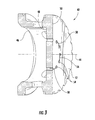
- Fig. 3 provides an enlarged perspective cross-section view of an exemplary nozzle tip 42 shown in Fig. 2 .
- the nozzle tip 42 generally comprises a body 46 having an upstream side 48, a downstream side 50, and a downstream surface 52.
- the body 46 and/or downstream surface 52 may be cast, forged, or sintered from a metal alloy or powdered metal allow to enhance the fatigue resistance of the nozzle tip 42 proximate to the combustion chamber 22.
- the nozzle tip 42 may further include a plurality of holes or passages 54 that extend through the body 46 and/or downstream surface 52 to provide fluid communication from the upstream side 48 to the downstream side 50 or through the body 46 and/or downstream surface 52.
- the holes or passages 54 may be aligned substantially parallel to or angled with respect to the axial centerline 44. In the particular embodiment illustrated in Fig. 3 , the holes or passages 54 are aligned substantially parallel to the axial centerline 44. In this manner, the passages 54 allow a fluid, such as a fuel, an oxidant, or a diluent, to flow through the body 46 and/or downstream surface 52 to cool the body 46, the downstream side 50 of the body 46, and/or downstream surface 52.
- a fluid such as a fuel, an oxidant, or a diluent
- the nozzle tip 42 may include one or more straight slits 56 and/or arcuate slits 58 in the downstream side or surface 50, 52 to relieve thermal stresses in the surface 52 of the body 46.
- Each slit 56, 58 may be machined into the downstream side or surface 50, 52 using conventional methods known in the art.
- the slits 56, 58 may be formed by grinding or using a laser, water jet, or electron discharge machining (EDM) process to melt the forged metal alloy to connect each slit 56, 58 to a pair of passages 54.
- EDM electron discharge machining
- each slit 56, 58 extends circumferentially in the downstream side or surface 50, 52 and connects to at least two passages 54.
- the width of each slit 56, 58 may vary between approximately 5 mils and 50 mils, and each slit 56, 58 may extend axially completely through the downstream surface 52 to the upstream side 48.
- 3 or 4 slits 56, 58 spaced equidistantly around the downstream surface 52 may provide adequate stress relief, while in other particular embodiments, each passage 54 may be connected to at least one slit 56, 58.
- Fig. 4 provides an enlarged perspective cross-section view of another exemplary nozzle tip 42 shown in Fig. 2 .
- the nozzle tip 42 again generally comprises a body 46, an upstream side 48, a downstream side 50, a downstream surface 52, and a plurality passages 54 as previously described with respect to the nozzle tip 42 shown in Fig. 3 .
- the passages 54 are generally angled radially and/or circumferentially with respect to the axial centerline 44 with a center passage 60 aligned substantially coincident with the axial centerline 44.
- the angled passages 54 enhance cooling to the downstream side or surface 50, 52 by swirling the fluid flowing through the passages 54, 60.
- first slits 62 are narrow and do not extend completely through the body 46, while second slits 64 are slightly wider and extend axially from the downstream surface 52 to the upstream side 48. In this manner, the first slits 62 allow less flow through the body 46 and more flow through the passages 54, 60. In addition, the amount of machining and removal of forged metal alloy from the downstream surface 52 may be reduced while providing adequate stress relief to the body 46 and/or downstream surface 52.
- a method for modifying the combustor nozzle 14 includes machining the slits 56, 58 in the downstream side or surface 50, 52 of the body 46, as previously described, and connecting each slit 56, 58 to at least two passages 54 that pass through the body 46.
- the method may include machining straight or arcuate slits 56, 58 and/or aligning the slits 56, 58 circumferentially and/or radially in the downstream side or surface 50, 52.
- the method may include connecting each passage 54, 60 to at least one slit 56, 58 and/or machining at least one slit 56, 58 completely through the body 46.
- the strategic location of the slits 56, 58 in the various embodiments contributes to increased durability of the nozzle 14 with minimal cost and impact on the nozzle 14 performance.
- the slits 56, 58 effectively function as pre-designed or built in cracks in the nozzle tip 42 that extend the effective life of the nozzle 14 by enhancing the crack fatigue resistance in the nozzle tip 42 and thus the overall reliability of the combustor 10.
Landscapes
- Engineering & Computer Science (AREA)
- Chemical & Material Sciences (AREA)
- Combustion & Propulsion (AREA)
- Mechanical Engineering (AREA)
- General Engineering & Computer Science (AREA)
- Turbine Rotor Nozzle Sealing (AREA)
- Gas Burners (AREA)
Abstract
Description
- The present invention generally involves a combustor nozzle and a method for modifying the combustor nozzle. In particular, various embodiments of the present invention provide a combustor nozzle with one or more slits in a downstream surface or side to enhance cracking fatigue resistance of the combustor nozzle.
- Combustors are commonly used to ignite fuel to produce combustion gases having a high temperature and pressure. Combustor nozzles typically include a body that forms a nozzle tip with a downstream surface, and a working fluid and/or fuel is supplied through the nozzle tip to a combustion chamber where the combustion occurs. The temperature difference between the working fluid and fuel on one side of the nozzle tip and the combustion gases on the other side of the nozzle tip creates a substantial thermal gradient across the nozzle tip that may produce cracking or premature failure in the nozzle tip. As a result, the nozzle tip is often forged from metal alloys and may also be coated with a thermal barrier coating to enhance fatigue resistance to cracking. Alternately or in addition, cooling holes or passages may be formed through the nozzle tip to allow a portion of the working fluid and/or fuel to pass through the nozzle tip to cool the downstream surface and reduce the temperature difference across the nozzle tip.
- The holes or passages may be machined into the nozzle tip using various methods known in the art. For example, electron discharge machining (EDM) may be used to melt the forged metal alloy to create the holes or passages. However, the high temperatures associated with the EDM process leaves a recast layer inside the holes or passages, and the recast layer is typically substantially less resistant to fatigue cracking than the original forged metal alloy. In addition, holes and passages that are angled with respect to an axial centerline of the nozzle tip to enhance cooling to the nozzle tip may result in unsupported portions of the nozzle tip that are more susceptible to fatigue cracking. Although in many cases, the additional cracking caused by the recast layer and/or unsupported portions is merely cosmetic, severe cracking may lead to material loss from the nozzle tip and possible downstream damage. Therefore, an improved combustor nozzle and/or method for modifying the combustor nozzle that enhances resistance to fatigue cracking would be useful.
- Aspects and advantages of the invention are set forth below in the following description, or may be obvious from the description, or may be learned through practice of the invention.
- One embodiment of the present invention is a combustor nozzle that includes a downstream surface having an axial centerline. A plurality of passages extend through the downstream surface and provide fluid communication through the downstream surface. A plurality of slits are included in the downstream surface, and each slit connects to at least two passages.
- Another embodiment of the present invention is a combustor nozzle that includes a body having an upstream side and a downstream side. A plurality of passages extend through the body and provide fluid communication from the upstream side to the downstream side. A plurality of slits are included in the downstream side, and each slit connects to at least two passages.
- The present invention may also include a method for modifying a combustor nozzle that includes machining a plurality of slits in a downstream side of a body. The method further includes connecting each slit to at least two passages that pass through the body.
- Those of ordinary skill in the art will better appreciate the features and aspects of such embodiments, and others, upon review of the specification.
- A full and enabling disclosure of the present invention, including the best mode thereof to one skilled in the art, is set forth more particularly in the remainder of the specification, including reference to the accompanying figures, in which:
-
Fig. 1 is a simplified cross-section view of an exemplary combustor; -
Fig. 2 is a cross-sectional perspective view of an exemplary combustor nozzle shown inFig. 1 ; -
Fig. 3 is an enlarged perspective cross-section view of an exemplary nozzle tip shown inFig. 2 modified according to a first embodiment of the present invention; -
Fig. 4 is an enlarged perspective cross-section view of an exemplary nozzle tip shown inFig. 2 modified according to a second embodiment of the present invention; and -
Fig. 5 is a top plan view of the nozzle tip shown inFig. 4 . - Reference will now be made in detail to present embodiments of the invention, one or more examples of which are illustrated in the accompanying drawings. The detailed description uses numerical and letter designations to refer to features in the drawings. Like or similar designations in the drawings and description have been used to refer to like or similar parts of the invention.
- Each example is provided by way of explanation of the invention, not limitation of the invention. In fact, it will be apparent to those skilled in the art that modifications and variations can be made in the present invention without departing from the scope or spirit thereof. For instance, features illustrated or described as part of one embodiment may be used on another embodiment to yield a still further embodiment. Thus, it is intended that the present invention covers such modifications and variations as come within the scope of the appended claims and their equivalents.
- Various embodiments of the present invention provide a combustor nozzle and a method for modifying the combustor nozzle that enhances resistance to fatigue cracking of the nozzle. The enhanced resistance to fatigue cracking may be achieved by one or more features or characteristics of the various embodiments of the present invention. For example, the combustor nozzle may include a plurality of passages through a body or a downstream surface of the combustor nozzle, and one or more slits may connect to at least two passages to provide stress relief in the body or downstream surface. In particular embodiments, the slits may be straight or curved and may extend circumferentially or radially between the passages. Theoretical thermal mapping may be used to predict the location of potential cracks and thus allow precise placement of the slits in particular nozzles to reduce high thermal stresses and enhance cracking fatigue resistance of the combustor nozzle. Although exemplary embodiments of the present invention will be described generally in the context of a combustor incorporated into a gas turbine for purposes of illustration, one of ordinary skill in the art will readily appreciate that embodiments of the present invention may be applied to any combustor and are not limited to a gas turbine combustor unless specifically recited in the claims.
-
Fig. 1 shows a simplified cross-section view of anexemplary combustor 10, such as would be included in a gas turbine. Acasing 12 may surround thecombustor 10 to contain the compressed working fluid flowing to thecombustor 10. As shown, thecombustor 10 may include one ormore nozzles 14 radially arranged between acap 16 and anend cover 18. Various embodiments of thecombustor 10 may include different numbers and arrangements ofnozzles 14. Thecap 16 and aliner 20 generally surround and define acombustion chamber 22 located downstream from thenozzles 14, and atransition piece 24 downstream from theliner 20 connects thecombustion chamber 22 to aturbine inlet 26. As used herein, the terms "upstream" and "downstream" refer to the relative location of components in a fluid pathway. For example, component A is upstream from component B if a fluid flows from component A to component B. Conversely, component B is downstream from component A if component B receives a fluid flow from component A. - An impingement sleeve 28 with
flow holes 30 may surround thetransition piece 24 to define anannular passage 32 between theimpingement sleeve 28 and thetransition piece 24. The compressed working fluid may pass through theflow holes 30 in theimpingement sleeve 28 to flow through theannular passage 32 to provide convective cooling to thetransition piece 24 andliner 20. When the compressed working fluid reaches theend cover 18, the compressed working fluid reverses direction to flow through the one ormore nozzles 14 where it mixes with fuel before igniting in thecombustion chamber 22 to produce combustion gases having a high temperature and pressure. -
Figure 2 provides a cross-sectional perspective view of anexemplary nozzle 14 shown inFig. 1 . As shown, thenozzle 14 may comprise ashroud 34 that circumferentially surrounds at least a portion of acenter body 36 to define anannular passage 38 between theshroud 34 and thecenter body 36. At least a portion of the working fluid may enter thenozzle 14 through theannular passage 38, and one or more swirler vanes 40 between theshroud 34 and thecenter body 36 may impart a tangential velocity to the compressed working fluid flowing through thenozzle 14. Thecenter body 36 may extend axially from theend cover 18 to anozzle tip 42, and thenozzle tip 42 may be axially aligned with or parallel to anaxial centerline 44 of thenozzle 14. In this manner, thecenter body 36 provides fluid communication from theend cover 18, through thecenter body 36, and out of thenozzle tip 42. -
Fig. 3 provides an enlarged perspective cross-section view of anexemplary nozzle tip 42 shown inFig. 2 . As shown, thenozzle tip 42 generally comprises abody 46 having anupstream side 48, adownstream side 50, and adownstream surface 52. Thebody 46 and/ordownstream surface 52 may be cast, forged, or sintered from a metal alloy or powdered metal allow to enhance the fatigue resistance of thenozzle tip 42 proximate to thecombustion chamber 22. Thenozzle tip 42 may further include a plurality of holes orpassages 54 that extend through thebody 46 and/ordownstream surface 52 to provide fluid communication from theupstream side 48 to thedownstream side 50 or through thebody 46 and/ordownstream surface 52. The holes orpassages 54 may be aligned substantially parallel to or angled with respect to theaxial centerline 44. In the particular embodiment illustrated inFig. 3 , the holes orpassages 54 are aligned substantially parallel to theaxial centerline 44. In this manner, thepassages 54 allow a fluid, such as a fuel, an oxidant, or a diluent, to flow through thebody 46 and/ordownstream surface 52 to cool thebody 46, thedownstream side 50 of thebody 46, and/ordownstream surface 52. - As shown in
Fig. 3 , thenozzle tip 42 may include one or morestraight slits 56 and/orarcuate slits 58 in the downstream side orsurface surface 52 of thebody 46. Each slit 56, 58 may be machined into the downstream side orsurface slits passages 54. The specific number, location, width, depth, and shape of each slit 56, 58 will depend on the particular geometry of thenozzle tip 42 and the anticipated thermal stresses in thebody 46 ordownstream surface 52. For example, in the particular embodiment shown inFig. 3 , each slit 56, 58 extends circumferentially in the downstream side orsurface passages 54. The width of each slit 56, 58 may vary between approximately 5 mils and 50 mils, and each slit 56, 58 may extend axially completely through thedownstream surface 52 to theupstream side 48. In particular embodiments, 3 or 4slits downstream surface 52 may provide adequate stress relief, while in other particular embodiments, eachpassage 54 may be connected to at least one slit 56, 58. -
Fig. 4 provides an enlarged perspective cross-section view of anotherexemplary nozzle tip 42 shown inFig. 2 . As shown, thenozzle tip 42 again generally comprises abody 46, anupstream side 48, adownstream side 50, adownstream surface 52, and aplurality passages 54 as previously described with respect to thenozzle tip 42 shown inFig. 3 . In the particular embodiment illustrated inFig. 4 , thepassages 54 are generally angled radially and/or circumferentially with respect to theaxial centerline 44 with acenter passage 60 aligned substantially coincident with theaxial centerline 44. Theangled passages 54 enhance cooling to the downstream side orsurface passages - In the embodiment shown in
Fig. 4 , the plurality ofstraight slits 56 extend radially in the downstream side orsurface passages Fig. 5 , the width and depth of thestraight slits 56 varies. Specifically, first slits 62 are narrow and do not extend completely through thebody 46, whilesecond slits 64 are slightly wider and extend axially from thedownstream surface 52 to theupstream side 48. In this manner, thefirst slits 62 allow less flow through thebody 46 and more flow through thepassages downstream surface 52 may be reduced while providing adequate stress relief to thebody 46 and/ordownstream surface 52. - The embodiments shown in
Figs. 3 and4 may be manufactured for use in new or existingnozzles 14, or existingnozzle tips 42 may be modified to achieve the desired stress relief. A method for modifying thecombustor nozzle 14 includes machining theslits surface body 46, as previously described, and connecting each slit 56, 58 to at least twopassages 54 that pass through thebody 46. Depending on the particular design needs, the method may include machining straight orarcuate slits slits surface passage body 46. - One of ordinary skill in the art will readily appreciate that the strategic location of the
slits nozzle 14 with minimal cost and impact on thenozzle 14 performance. Theslits nozzle tip 42 that extend the effective life of thenozzle 14 by enhancing the crack fatigue resistance in thenozzle tip 42 and thus the overall reliability of thecombustor 10. - This written description uses examples to disclose the invention, including the best mode, and also to enable any person skilled in the art to practice the invention, including making and using any devices or systems and performing any incorporated methods. The patentable scope of the invention is defined by the claims, and may include other examples that occur to those skilled in the art. Such other and examples are intended to be within the scope of the claims if they include structural elements that do not differ from the literal language of the claims, or if they include equivalent structural elements with insubstantial differences from the literal languages of the claims.
Claims (14)
- A combustor nozzle (14), comprising:a. a downstream surface (52) having an axial centerline (44);b. a plurality of passages (54) extending through the downstream surface (52), wherein the plurality of passages (54) provide fluid communication through the downstream surface (52); andc. a plurality of slits (56, 58) in the downstream surface (52), wherein each slit (56, 58) connects to at least two passages (54).
- The combustor nozzle (14) as in claim 1, wherein each passage (54) is aligned substantially parallel to the axial centerline (44) of the downstream surface (52).
- The combustor nozzle (14) as in any preceding claim, wherein each passage (54) is connected to at least one slit (56, 58).
- The combustor nozzle (14) as in any preceding claim, wherein at least one slit (56, 58) extends circumferentially in the downstream surface (52) between at least two passages (54).
- The combustor nozzle (14) as in any preceding claim, wherein at least one slit (56, 58) extends radially in the downstream surface (52) between at least two passages (54).
- The combustor nozzle (14) as in any preceding claim, wherein at least one slit (56, 58) is arcuate between at least two passages (54).
- The combustor nozzle (14) as in any preceding claim, further comprising an upstream side (48) opposed to the downstream surface (52), and wherein the plurality of slits (58) extend axially from the downstream surface (52) to the upstream side (48).
- A method for modifying a combustor nozzle (14), comprising:a. machining a plurality of slits (56, 58) in a downstream side (50) of a body (46); andb. connecting each slit (56, 58) to at least two passages (54) that pass through the body (46).
- The method as in claim 8, further comprising connecting each passage (54) to at least one slit (56, 58).
- The method as in claim 8 or 9, further comprising aligning at least one slit (56, 58) circumferentially in the downstream side (50) between at least two passages (54).
- The method as in any of claims 8 to 10, further comprising aligning at least one slit (56, 58) radially in the downstream side (50) between at least two passages (54).
- The method as in any of claims 8 to 11, further comprising machining at least one arcuate slit (58) between at least two passages (54).
- The method as in any of claims 8 to 12, further comprising machining at least one slit (56, 58) completely through the body (46).
- The combustor nozzle as in Claim 1, comprising:a. a body (46) having an upstream side (48) and a downstream side (50);
andb. said plurality of passages (54) extending through the body, wherein the plurality of passages provide fluid communication from the upstream side to the downstream side.
Applications Claiming Priority (1)
| Application Number | Priority Date | Filing Date | Title |
|---|---|---|---|
| US13/153,504 US8794544B2 (en) | 2011-06-06 | 2011-06-06 | Combustor nozzle and method for modifying the combustor nozzle |
Publications (2)
| Publication Number | Publication Date |
|---|---|
| EP2532967A2 true EP2532967A2 (en) | 2012-12-12 |
| EP2532967A3 EP2532967A3 (en) | 2014-01-08 |
Family
ID=46197166
Family Applications (1)
| Application Number | Title | Priority Date | Filing Date |
|---|---|---|---|
| EP12171076.8A Withdrawn EP2532967A3 (en) | 2011-06-06 | 2012-06-06 | Combustor nozzle and method for modifying the combustor nozzle |
Country Status (3)
| Country | Link |
|---|---|
| US (1) | US8794544B2 (en) |
| EP (1) | EP2532967A3 (en) |
| CN (1) | CN102818284B (en) |
Families Citing this family (3)
| Publication number | Priority date | Publication date | Assignee | Title |
|---|---|---|---|---|
| EP2923150B1 (en) * | 2012-11-21 | 2018-09-05 | General Electric Company | Anti-coking liquid fuel cartridge |
| WO2020180294A1 (en) * | 2019-03-04 | 2020-09-10 | Siemens Energy, Inc. | Fuel injection nozzle including a heat shield |
| EP4083509B1 (en) * | 2021-04-30 | 2024-12-25 | Ansaldo Energia Switzerland AG | Method for calibrating a gas turbine burner during recondition or production by using a calibrating pin |
Family Cites Families (10)
| Publication number | Priority date | Publication date | Assignee | Title |
|---|---|---|---|---|
| US5228283A (en) * | 1990-05-01 | 1993-07-20 | General Electric Company | Method of reducing nox emissions in a gas turbine engine |
| US5222357A (en) * | 1992-01-21 | 1993-06-29 | Westinghouse Electric Corp. | Gas turbine dual fuel nozzle |
| EP0924458B1 (en) | 1997-12-22 | 2002-08-28 | Alstom | Burner |
| KR100550689B1 (en) * | 1998-02-10 | 2006-02-08 | 제너럴 일렉트릭 캄파니 | Burners for combustion systems of gas turbines and methods for premixing fuel and air |
| US6823677B2 (en) | 2002-09-03 | 2004-11-30 | Pratt & Whitney Canada Corp. | Stress relief feature for aerated gas turbine fuel injector |
| US6910853B2 (en) * | 2002-11-27 | 2005-06-28 | General Electric Company | Structures for attaching or sealing a space between components having different coefficients or rates of thermal expansion |
| FR2897143B1 (en) * | 2006-02-08 | 2012-10-05 | Snecma | COMBUSTION CHAMBER OF A TURBOMACHINE |
| US8261554B2 (en) | 2008-09-17 | 2012-09-11 | General Electric Company | Fuel nozzle tip assembly |
| US8495881B2 (en) * | 2009-06-02 | 2013-07-30 | General Electric Company | System and method for thermal control in a cap of a gas turbine combustor |
| US9200571B2 (en) * | 2009-07-07 | 2015-12-01 | General Electric Company | Fuel nozzle assembly for a gas turbine engine |
-
2011
- 2011-06-06 US US13/153,504 patent/US8794544B2/en not_active Expired - Fee Related
-
2012
- 2012-06-06 EP EP12171076.8A patent/EP2532967A3/en not_active Withdrawn
- 2012-06-06 CN CN201210249226.6A patent/CN102818284B/en not_active Expired - Fee Related
Non-Patent Citations (1)
| Title |
|---|
| None |
Also Published As
| Publication number | Publication date |
|---|---|
| CN102818284A (en) | 2012-12-12 |
| CN102818284B (en) | 2015-12-09 |
| US20120308948A1 (en) | 2012-12-06 |
| US8794544B2 (en) | 2014-08-05 |
| EP2532967A3 (en) | 2014-01-08 |
Similar Documents
| Publication | Publication Date | Title |
|---|---|---|
| US9316396B2 (en) | Hot gas path duct for a combustor of a gas turbine | |
| US9464538B2 (en) | Shroud block segment for a gas turbine | |
| CN102733860B (en) | Turbine shroud portion section cooling system and method | |
| US9556795B2 (en) | Integrated heat shield | |
| CN103307633A (en) | A fuel nozzle and a combustor for a gas turbine | |
| CA2713576C (en) | Fuel nozzle swirler assembly | |
| US11499434B2 (en) | Cooled airfoil and method of making | |
| US8646279B2 (en) | Segment component in high-temperature casting material for an annular combustion chamber, annular combustion chamber for an aircraft engine, aircraft engine and method for the manufacture of an annular combustion chamber | |
| EP2679775A1 (en) | A transition duct for a gas turbine | |
| JP6161945B2 (en) | Fuel nozzle | |
| KR102715377B1 (en) | Two portion cooling passage for airfoil | |
| JP2016133117A (en) | Turbine shroud assembly | |
| US8794544B2 (en) | Combustor nozzle and method for modifying the combustor nozzle | |
| CN203835465U (en) | Cooling channels of turbine blades of gas turbine engine | |
| JP2019105437A (en) | Aft frame assembly for gas turbine transition piece | |
| CN108019240B (en) | Gas turbine and cooled structure thereof | |
| CN107035436B (en) | System and method for cooling a turbine shroud | |
| CN109667628A (en) | Afterframe component for gas turbine transition piece | |
| US20190249554A1 (en) | Engine component with cooling hole | |
| CN109667668A (en) | Afterframe component for gas turbine transition piece | |
| JP2017110655A (en) | Method for metering a microchannel circuit | |
| EP2532966B1 (en) | Combustion nozzle and method for modifying the combustor nozzle | |
| US10738638B2 (en) | Rotor blade with wheel space swirlers and method for forming a rotor blade with wheel space swirlers | |
| EP2532957A2 (en) | System for conditioning flow through a nozzle |
Legal Events
| Date | Code | Title | Description |
|---|---|---|---|
| PUAI | Public reference made under article 153(3) epc to a published international application that has entered the european phase |
Free format text: ORIGINAL CODE: 0009012 |
|
| AK | Designated contracting states |
Kind code of ref document: A2 Designated state(s): AL AT BE BG CH CY CZ DE DK EE ES FI FR GB GR HR HU IE IS IT LI LT LU LV MC MK MT NL NO PL PT RO RS SE SI SK SM TR |
|
| AX | Request for extension of the european patent |
Extension state: BA ME |
|
| PUAL | Search report despatched |
Free format text: ORIGINAL CODE: 0009013 |
|
| AK | Designated contracting states |
Kind code of ref document: A3 Designated state(s): AL AT BE BG CH CY CZ DE DK EE ES FI FR GB GR HR HU IE IS IT LI LT LU LV MC MK MT NL NO PL PT RO RS SE SI SK SM TR |
|
| AX | Request for extension of the european patent |
Extension state: BA ME |
|
| RIC1 | Information provided on ipc code assigned before grant |
Ipc: F23R 3/28 20060101AFI20131203BHEP |
|
| 17P | Request for examination filed |
Effective date: 20140708 |
|
| RBV | Designated contracting states (corrected) |
Designated state(s): AL AT BE BG CH CY CZ DE DK EE ES FI FR GB GR HR HU IE IS IT LI LT LU LV MC MK MT NL NO PL PT RO RS SE SI SK SM TR |
|
| 17Q | First examination report despatched |
Effective date: 20170215 |
|
| STAA | Information on the status of an ep patent application or granted ep patent |
Free format text: STATUS: THE APPLICATION IS DEEMED TO BE WITHDRAWN |
|
| 18D | Application deemed to be withdrawn |
Effective date: 20180103 |