EP2532891A1 - Rotary blade of windmill and method of manufacturing rotary blade of windmill - Google Patents
Rotary blade of windmill and method of manufacturing rotary blade of windmill Download PDFInfo
- Publication number
- EP2532891A1 EP2532891A1 EP10839557A EP10839557A EP2532891A1 EP 2532891 A1 EP2532891 A1 EP 2532891A1 EP 10839557 A EP10839557 A EP 10839557A EP 10839557 A EP10839557 A EP 10839557A EP 2532891 A1 EP2532891 A1 EP 2532891A1
- Authority
- EP
- European Patent Office
- Prior art keywords
- crossbeam
- wind turbine
- turbine rotor
- disposed
- blade
- Prior art date
- Legal status (The legal status is an assumption and is not a legal conclusion. Google has not performed a legal analysis and makes no representation as to the accuracy of the status listed.)
- Granted
Links
Images


Classifications
-
- F—MECHANICAL ENGINEERING; LIGHTING; HEATING; WEAPONS; BLASTING
- F03—MACHINES OR ENGINES FOR LIQUIDS; WIND, SPRING, OR WEIGHT MOTORS; PRODUCING MECHANICAL POWER OR A REACTIVE PROPULSIVE THRUST, NOT OTHERWISE PROVIDED FOR
- F03D—WIND MOTORS
- F03D1/00—Wind motors with rotation axis substantially parallel to the air flow entering the rotor
- F03D1/06—Rotors
- F03D1/065—Rotors characterised by their construction elements
- F03D1/0675—Rotors characterised by their construction elements of the blades
-
- B—PERFORMING OPERATIONS; TRANSPORTING
- B29—WORKING OF PLASTICS; WORKING OF SUBSTANCES IN A PLASTIC STATE IN GENERAL
- B29L—INDEXING SCHEME ASSOCIATED WITH SUBCLASS B29C, RELATING TO PARTICULAR ARTICLES
- B29L2031/00—Other particular articles
- B29L2031/08—Blades for rotors, stators, fans, turbines or the like, e.g. screw propellers
- B29L2031/082—Blades, e.g. for helicopters
- B29L2031/085—Wind turbine blades
-
- Y—GENERAL TAGGING OF NEW TECHNOLOGICAL DEVELOPMENTS; GENERAL TAGGING OF CROSS-SECTIONAL TECHNOLOGIES SPANNING OVER SEVERAL SECTIONS OF THE IPC; TECHNICAL SUBJECTS COVERED BY FORMER USPC CROSS-REFERENCE ART COLLECTIONS [XRACs] AND DIGESTS
- Y02—TECHNOLOGIES OR APPLICATIONS FOR MITIGATION OR ADAPTATION AGAINST CLIMATE CHANGE
- Y02E—REDUCTION OF GREENHOUSE GAS [GHG] EMISSIONS, RELATED TO ENERGY GENERATION, TRANSMISSION OR DISTRIBUTION
- Y02E10/00—Energy generation through renewable energy sources
- Y02E10/70—Wind energy
- Y02E10/72—Wind turbines with rotation axis in wind direction
-
- Y—GENERAL TAGGING OF NEW TECHNOLOGICAL DEVELOPMENTS; GENERAL TAGGING OF CROSS-SECTIONAL TECHNOLOGIES SPANNING OVER SEVERAL SECTIONS OF THE IPC; TECHNICAL SUBJECTS COVERED BY FORMER USPC CROSS-REFERENCE ART COLLECTIONS [XRACs] AND DIGESTS
- Y02—TECHNOLOGIES OR APPLICATIONS FOR MITIGATION OR ADAPTATION AGAINST CLIMATE CHANGE
- Y02P—CLIMATE CHANGE MITIGATION TECHNOLOGIES IN THE PRODUCTION OR PROCESSING OF GOODS
- Y02P70/00—Climate change mitigation technologies in the production process for final industrial or consumer products
- Y02P70/50—Manufacturing or production processes characterised by the final manufactured product
-
- Y—GENERAL TAGGING OF NEW TECHNOLOGICAL DEVELOPMENTS; GENERAL TAGGING OF CROSS-SECTIONAL TECHNOLOGIES SPANNING OVER SEVERAL SECTIONS OF THE IPC; TECHNICAL SUBJECTS COVERED BY FORMER USPC CROSS-REFERENCE ART COLLECTIONS [XRACs] AND DIGESTS
- Y10—TECHNICAL SUBJECTS COVERED BY FORMER USPC
- Y10T—TECHNICAL SUBJECTS COVERED BY FORMER US CLASSIFICATION
- Y10T156/00—Adhesive bonding and miscellaneous chemical manufacture
- Y10T156/10—Methods of surface bonding and/or assembly therefor
- Y10T156/1002—Methods of surface bonding and/or assembly therefor with permanent bending or reshaping or surface deformation of self sustaining lamina
- Y10T156/1028—Methods of surface bonding and/or assembly therefor with permanent bending or reshaping or surface deformation of self sustaining lamina by bending, drawing or stretch forming sheet to assume shape of configured lamina while in contact therewith
- Y10T156/103—Encasing or enveloping the configured lamina
Definitions
- the present invention relates to a wind turbine rotor blade constituting a wind-generating wind turbine, and to a producing method of the wind turbine rotor blade.
- the wind turbine rotor blade 100 having a super cap structure which satisfies both lightweight requirement and strength requirement as shown in Fig. 7 .
- the wind turbine rotor blade 100 includes outer skin materials 11, leading edge sandwich materials 12, main strength materials (super cap materials) 101, trailing edge sandwich materials 14, sheer webs (crossbeam materials) 15, and inner skin materials 17.
- the leading edge sandwich materials 12 and the trailing edge sandwich materials 14 have a sandwich structure in which the outer skin material 11 and the inner skin material 17 form a skin material, and a resin foam body such as PVC and wood material such as balsa form a core material.
- a symbol 16 represents an adhesive which connects the main strength material 101 and the sheer web 15 to each other.
- a shape of the wind turbine rotor blade 100 (outer shape and sizes of various members) as viewed from the above is varied in a longitudinal direction of the blade, and in accordance with this variation, a plurality of sheets whose widths are varied in the longitudinal direction are cut out from a reinforced fiber sheet (glass fiber cloth, glass fiber preimpregnation, carbon fiber cloth or carbon fiber preimpregnation for example) which is supplied from a fiber maker and which have a constant width, and the plurality of cut sheets are stacked one on top of another, thereby producing main strength materials 101. Therefore, there is a problem that the cut raw material is discarded and wasted, and a producing cost is increased.
- a reinforced fiber sheet glass fiber cloth, glass fiber preimpregnation, carbon fiber cloth or carbon fiber preimpregnation for example
- the present invention has been accomplished in view of the above circumstances, and it is an object of the invention to provide a wind turbine rotor blade and a producing method of the wind turbine rotor blade capable of eliminating wastes of raw material when a main strength material (super cap material) is produced, and capable of reducing a producing cost.
- a wind turbine rotor blade includes an outer skin material formed of fiber-reinforced plastic, main strength materials disposed on inner surfaces of a back side and a front side of the outer skin material, and crossbeam materials disposed between the main strength materials, wherein the main strength material is formed by stacking, one on top of another, reinforced fiber sheets having constant widths in a longitudinal direction.
- the main strength material is formed (configured) by merely stacking, one on top of another, the reinforced fiber sheets which are supplied from a fiber maker and which have constant widths, the wastes when the main strength material is produced can be eliminated, and the producing cost can be reduced.
- the number of stacked reinforced fiber sheets constituting the main strength material is selected in accordance with a strength required at a position in a rotation radial direction of the wind turbine rotor blade.
- the crossbeam materials are disposed such that a distance between the crossbeam material disposed on a leading edge side and the crossbeam material disposed on a trailing edge side that constitute the crossbeam materials is maintained constantly from a root side to a tip end side of the blade.
- the crossbeam materials are disposed such that a distance between the crossbeam material disposed on a leading edge side and the crossbeam material disposed on a trailing edge side that constitute the crossbeam materials is gradually narrowed linearly from a root side to a tip end side of the blade.
- root side of a blade means one end side of the blade mounted on the rotor head
- tip end side of a blade means the other end side of the blade which becomes a free end when the blade is mounted on the rotor head.
- a distance between a crossbeam material disposed on a leading edge side and a crossbeam material disposed on a trailing edge side is varied non-linearly from the root side to the tip end side of a blade while taking, into account, a width of the wind turbine rotor blade (which is varied in the longitudinal direction of the blade).
- this distance between the crossbeam materials can be maintained constantly or varied linearly, it is possible to easily and swiftly carry out a positioning operation when the crossbeam material is fixed to a special jig called gantry for mounting (adhering) the crossbeam material on the main strength material, time required for the producing operation can be shortened, and the productivity can be enhanced.
- the crossbeam material is disposed without being twisted from the root side to the tip end side of the blade.
- the crossbeam material is also twisted from the root side to the tip end side of the blade while taking, into account, a twist of a cross section of the blade around an axis in the longitudinal direction of the blade.
- the twist of the crossbeam material becomes unnecessary, it is possible to reduce a producing cost of a mold which is used when the crossbeam material is produced, and it is possible to produce the crossbeam material more easily and more swiftly as compared with the conventional technique.
- twist means “twist up” for gradually increasing an angle of attack of the wind turbine rotor blade toward a tip end (blade end) of a blade, or “twist down” for gradually reducing the angle of attack of the wind turbine rotor blade toward the tip end (blade end) of the blade.
- the wind-generating wind turbine of the second aspect of the invention has a wind turbine rotor blade capable of eliminating the wastes of raw material when the main strength material is produced, and capable of reducing the producing cost.
- the wind-generating wind turbine of the second aspect of the invention it is possible to contribute to a terrestrial environment problem, and to reduce the producing cost.
- a producing method of a wind turbine rotor blade which includes an outer skin material formed of fiber-reinforced plastic, main strength materials disposed on inner surfaces of a back side and a front side of the outer skin material, and crossbeam materials disposed between the main strength materials
- the producing methods includes: a step of stacking, one on top of another, reinforced fiber sheets having constant widths in a longitudinal direction to prepare the main strength material; a step of placing the outer skin material forming a back side surface on a first formwork forming a back side half-cut blade, and placing, on the outer skin material, the main strength material which is disposed on a back side of the crossbeam material; and a step of placing the outer skin material forming a front side surface on a second formwork forming a front side half-cut blade, and placing, on the outer skin material, the main strength material which is disposed on a front side of the crossbeam material.
- the main strength material is formed (configured) by merely stacking, one on top of another, the reinforced fiber sheets which are supplied from a fiber maker and which have constant widths without cutting the reinforced fiber sheets in accordance with variation in a shape of the wind turbine rotor blade as viewed from above in the longitudinal direction of the blade. Therefore, it is possible to eliminate the wastes of raw material when the main strength material is produced, and to reduce the producing cost.
- the crossbeam materials are disposed such that a distance between the crossbeam material disposed on a leading edge side and the crossbeam material disposed on a trailing edge side that constitute the crossbeam materials is maintained constantly from a root side to a tip end side of the blade.
- the crossbeam materials are disposed such that a distance between the crossbeam material disposed on a leading edge side and the crossbeam material disposed on a trailing edge side that constitute the crossbeam materials is gradually narrowed linearly from a root side to a tip end side of the blade.
- the producing method of the wind turbine rotor blade when the crossbeam material is produced, it is unnecessary to vary the distance between the crossbeam material disposed on the leading edge side and the crossbeam material disposed on the trailing edge side from the root side to the tip end side of the blade while taking the width of the wind turbine rotor blade into account. Therefore, it is possible to easily and swiftly carry out the positioning operation when the crossbeam material is fixed to the special jig called gantry for mounting (adhering) the crossbeam material on the main strength material, time required for the producing operation can be shortened, and the productivity can be enhanced.
- the crossbeam material is produced without being twisted from the root side to the tip end side of the blade.
- the producing method of the wind turbine rotor blade when the crossbeam material is produced, it is unnecessary to twist the crossbeam material from the root side to the tip end side of the blade while taking the twist of the wind turbine rotor blade into account. Therefore, it is possible to reduce the producing cost of the mold which is used when the crossbeam material is produced, and it is possible to more easily and more swiftly produce the crossbeam material. Further, since it is possible to more easily and more swiftly carry out the positioning operation when the crossbeam material is fixed to the special jig called gantry for mounting (adhering) the crossbeam material on the main strength material, time required for the producing operation can further be shortened, and the productivity can further be enhanced.
- the wind turbine rotor blade and the producing method of the wind turbine rotor blade of the present invention there is an effect that it is possible to eliminate the wastes of raw material when the main strength material is produced, and to reduce the producing cost.
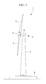
- FIG. 1 is a side view showing a wind-generating wind turbine having the wind turbine rotor blades according to a first embodiment of the present invention.
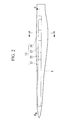
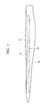
- Fig. 2 is a plan view of the wind turbine rotor blade according to the first embodiment of the invention.
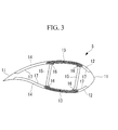
- Fig. 3 is a sectional view taken along the arrows A-A in Fig. 2 .
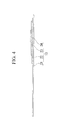
- Fig. 4 is a sectional view taken along the arrows B-B in Fig. 2 .
- a twist up from a blade root (root) to a blade end (tip end) of the wind turbine rotor blade is not taken into account (not shown).
- Fig. 4 shows only a super cap material located on a back side.
- the wind-generating wind turbine 1 includes a column (also called “tower") 2 standing on a foundation B, a nacelle 3 disposed on an upper end of the column 2, and a rotor head 4 provided on a nacelle 3 such that the rotor head 4 can rotate around a substantially horizontal axis.
- a plurality of (e.g., three) wind turbine rotor blades 5 are radially mounted on the rotor head 4 around its rotation axis. According to this, a force of wind which impinges on the wind turbine rotor blades 5 from the rotation axis of the rotor head 4 is converted into power which rotates the rotor head 4 around its rotation axis.
- the column 2 is formed by connecting a plurality of (e.g., three) units (not shown) in the vertical direction.
- the nacelle 3 is disposed on the uppermost one of the units which constitute the column 2.
- the nacelle 3 includes a nacelle bed plate (not shown) mounted on the upper end of the column 2, and a cover 6 covering the nacelle bed plate from above.
- each of the wind turbine rotor blades 5 is formed as a super cap structure which satisfies both lightweight requirement and strength requirement.
- the wind turbine rotor blade 5 includes outer skin materials 11, leading edge sandwich materials 12, super cap materials (main strength material) 13, trailing edge sandwich materials 14 and sheer webs (crossbeam materials) 15, and inner skin materials 17.
- the outer skin material 11, the super cap material 13 and an inner skin material 17 are made (formed) of fiber-reinforced plastic (FRP).
- the super cap material 13 is formed by laminating many reinforced fiber sheets on one another, and the super cap material 13 is provided on a back side of the wind turbine rotor blade 5 (upper side in Fig. 3 ) and a front side (lower side in Fig. 3 ) one each.
- the super cap materials 13 and the sheer webs 15 are connected (coupled) to each other through an adhesive 16 which is cured at room temperature.
- the leading edge sandwich material 12 and the trailing edge sandwich material 14 have a sandwich structure in which the outer skin material 11 and the inner skin material 17 form a skin material, and a resin foam body such as PVC and wood material such as balsa form a core material.
- the super cap structure the bending strength of the wind turbine rotor blade 5 in a flap direction is maintained mainly by the super cap material 13 which is a member obtained by laminating many reinforced fiber sheets on one another.
- the leading edge sandwich material 12 and the trailing edge sandwich material 14 are auxiliary used for maintaining the buckling strength of the wind turbine rotor blade 5.
- the wind turbine rotor blade 5 of the embodiment includes the super cap materials 13 as shown in Figs. 2 and 4 .
- each of the super cap materials 13 has a constant width (length in a cord direction (vertical direction in Fig. 2 )) from a root side to a tip end side of the blade and as shown in Fig. 4 , the super cap material 13 is formed by laminating, on one another, reinforced fiber sheets 21, 22, 23 and 24 having different lengths in a longitudinal direction of the blade (lateral direction in Fig. 2 ) as shown in Figs. 2 and 4 .
- the super cap material 13 when the super cap material 13 is in a certain position of the wind turbine rotor blade 5 in its longitudinal direction (generally, a radial position when the blade rotates in a range of 40 to 60%), all of the reinforced fiber sheets 21, 22, 23 and 24 are laminated on one another, and the number of the laminated reinforced fiber sheets 21, 22, 23 and 24 is gradually reduced from a position where the number of the laminated sheets is the maximum toward the root side and the tip end side of the blade.
- the number of the laminated reinforced fiber sheets 21, 22, 23 and 24 is selected in accordance with a strength required at a position in the rotation radial direction of the wind turbine rotor blade.
- the reinforced fiber sheets 21, 22, 23 and 24 have the same widths and the same thicknesses. While taking the width of the wind turbine rotor blade 5 into account, a distance between the sheer web 15 disposed on the leading edge side and the sheer web 15 disposed on the trailing edge side is proportional to a length of the blade in a cord direction which is varied from the root side to the tip end side of the blade. The blade is twisted in accordance with a predetermined twist up which is set from the blade root to the blade end.
- the super cap material 13 is formed (configured) by merely stacking, one on top of another, the reinforced fiber sheets which are supplied from a fiber maker and which have constant widths without cutting the reinforced fiber sheets in accordance with a shape of the wind turbine rotor blade 5 as viewed from above. Therefore, it is possible to eliminate the wastes of raw material when the super cap material 13 is produced, and to reduce the producing cost.
- the number of the laminated reinforced fiber sheets 21, 22, 23 and 24 constituting the super cap material 13 is selected in accordance with a strength required at a position in the rotation radial direction of the wind turbine rotor blade. According to this, since a strength required as the super cap material 13 is secured, it is possible to prevent brittle fracture, fatigue fracture and buckling against a load in a flap direction (longitudinal direction) of the super cap material 13.
- the producing method of the wind turbine rotor blade 5 of this embodiment includes: a step of stacking, one on top of another, reinforced fiber sheets 21, 22, 23 and 24 having constant widths in a longitudinal direction to prepare the super cap material 13; a step of placing the outer skin material 11 forming a back side surface on a first formwork (not shown) forming a back side half-cut blade, and placing, on the outer skin material 11, the super cap material 13 which is disposed on a back side of the sheer web 15; and a step of placing the outer skin material 11 forming a front side surface on a second formwork (not shown) forming a front side half-cut blade, and placing, on the outer skin material 11, the super cap material 13 which is disposed on a front side of the sheer web 15.
- the super cap material 13 is formed (configured) by cutting, to a desired length, the reinforced fiber sheets which are supplied from a fiber maker and which have constant widths without cutting the reinforced fiber sheets in accordance with a width of the wind turbine rotor blade 5, and by merely stacking the reinforced fiber sheets one on top of another. Therefore, it is possible to eliminate the wastes of raw material when the super cap material 13 is produced, and to reduce the producing cost.
- FIG. 5 is a plan view of the wind turbine rotor blade according to the second embodiment.
- a twist up from a blade root (root) to a blade end (tip end) of the wind turbine rotor blade is not taken into account (not shown).
- a wind turbine rotor blade 30 according to the second embodiment is different from that of the first embodiment in that the blade includes sheer webs 31 instead of the sheer webs 15. Since other constituent elements are the same as those of the first embodiment, description of these constituent elements is omitted. The same members as those of the first embodiment are designated with the same symbols.
- the sheer webs 31 are disposed such that a distance between the sheer webs 31 (a distance between the sheer web 31 disposed on a leading edge side and the sheer web 31 disposed on a trailing edge side) is maintained constantly from a root side to a tip end side of the blade.
- the sheer web 31 is twisted in accordance with a predetermined twist up which is set from the root side to the tip end side of the wind turbine rotor blade 30.
- the distance between the sheer web 31 disposed on the leading edge side and the sheer web 31 disposed on the trailing edge side is varied non-linearly from the root side to the tip end side of the blade while taking, into account, a width of the wind turbine rotor blade (which is varied in the longitudinal direction of the blade). According to the wind turbine rotor blade 30 and the producing method of the wind turbine rotor blade 30 of this embodiment, this distance between the sheer webs 31 can be maintained constantly.
- FIG. 6 is a plan view of the wind turbine rotor blade according to the third embodiment.
- a twist up from a blade root (root) to a blade end (tip end) of the wind turbine rotor blade is not taken into account (not shown).
- the wind turbine rotor blade 40 according to the third embodiment is different from that of the first embodiment in that the blade includes sheer webs 41 instead of the sheer webs 15. Since other constituent elements are the same as those of the first embodiment, description of these constituent elements is omitted. The same members as those of the first embodiment are designated with the same symbols.
- the sheer webs 41 are disposed such that a distance between the sheer webs 41 (a distance between the sheer web 41 disposed on a leading edge side and the sheer web 41 disposed on a trailing edge side) is gradually narrowed linearly from the root side to the tip end side of the blade, i.e., such that a shape of the sheer web 41 as viewed from above is tapered toward the tip end side of the blade from the root side.
- the sheer web 41 is twisted in accordance with a predetermined twist up which is set from the root side to the tip end side of the wind turbine rotor blade 40.
- the distance between the sheer web 41 disposed on the leading edge side and the sheer web 41 disposed on the trailing edge side is varied non-linearly from the root side to the tip end side of a blade while taking, into account, a width of the wind turbine rotor blade (which is varied in the longitudinal direction of the blade).
- this distance between the sheer webs 41 can be varied linearly.
- the sheer web 31, 41 is not twisted from the root side to the tip end side of the wind turbine rotor blade 30, 40 and is disposed (accommodated) in the outer skin material 11 while keeping its outer shape flatly.
- the sheer web 31, 41 is disposed in the outer skin material 11 while keeping its outer shape flatly, it is unnecessary to twist the sheer web 31, 41 from the root side to the tip end side of the blade while taking, into account, the twist down of the wind turbine rotor blade 30, 40 when the sheer web 31, 41 is produced. Therefore, it is possible to reduce the producing cost of a mold used when the crossbeam material is produced, and it is possible to more easily and swiftly produce the sheer web 31, 41.
Landscapes
- Engineering & Computer Science (AREA)
- Life Sciences & Earth Sciences (AREA)
- Sustainable Development (AREA)
- Sustainable Energy (AREA)
- Chemical & Material Sciences (AREA)
- Combustion & Propulsion (AREA)
- Mechanical Engineering (AREA)
- General Engineering & Computer Science (AREA)
- Wind Motors (AREA)
Abstract
Description
- The present invention relates to a wind turbine rotor blade constituting a wind-generating wind turbine, and to a producing method of the wind turbine rotor blade.
- As a wind turbine rotor blade, one disclosed in
patent document 1 is known for example. -
- {PTL 1} PCT International Publication No.
2008/086805 - In recent years, there has been proposed a wind
turbine rotor blade 100 having a super cap structure which satisfies both lightweight requirement and strength requirement as shown inFig. 7 . The windturbine rotor blade 100 includesouter skin materials 11, leadingedge sandwich materials 12, main strength materials (super cap materials) 101, trailingedge sandwich materials 14, sheer webs (crossbeam materials) 15, andinner skin materials 17. The leadingedge sandwich materials 12 and the trailingedge sandwich materials 14 have a sandwich structure in which theouter skin material 11 and theinner skin material 17 form a skin material, and a resin foam body such as PVC and wood material such as balsa form a core material.
InFig. 7 , asymbol 16 represents an adhesive which connects themain strength material 101 and thesheer web 15 to each other. - However, according to such a wind
turbine rotor blade 100, a shape of the wind turbine rotor blade 100 (outer shape and sizes of various members) as viewed from the above is varied in a longitudinal direction of the blade, and in accordance with this variation, a plurality of sheets whose widths are varied in the longitudinal direction are cut out from a reinforced fiber sheet (glass fiber cloth, glass fiber preimpregnation, carbon fiber cloth or carbon fiber preimpregnation for example) which is supplied from a fiber maker and which have a constant width, and the plurality of cut sheets are stacked one on top of another, thereby producingmain strength materials 101. Therefore, there is a problem that the cut raw material is discarded and wasted, and a producing cost is increased. - The present invention has been accomplished in view of the above circumstances, and it is an object of the invention to provide a wind turbine rotor blade and a producing method of the wind turbine rotor blade capable of eliminating wastes of raw material when a main strength material (super cap material) is produced, and capable of reducing a producing cost.
- To solve the above problem, the present invention employed the following means.
A wind turbine rotor blade according to a first aspect of the invention includes an outer skin material formed of fiber-reinforced plastic, main strength materials disposed on inner surfaces of a back side and a front side of the outer skin material, and crossbeam materials disposed between the main strength materials, wherein the main strength material is formed by stacking, one on top of another, reinforced fiber sheets having constant widths in a longitudinal direction. - According to the wind turbine rotor blade of the first aspect of the invention, since the main strength material is formed (configured) by merely stacking, one on top of another, the reinforced fiber sheets which are supplied from a fiber maker and which have constant widths, the wastes when the main strength material is produced can be eliminated, and the producing cost can be reduced.
- In the wind turbine rotor blade, it is further preferable if the number of stacked reinforced fiber sheets constituting the main strength material is selected in accordance with a strength required at a position in a rotation radial direction of the wind turbine rotor blade.
- According to such a wind turbine rotor blade, since a necessary strength as the main strength material can be secured, it is possible to prevent brittle fracture, fatigue fracture and buckling against a load in a flap direction (longitudinal direction).
- In the wind turbine rotor blade, it is preferable that the crossbeam materials are disposed such that a distance between the crossbeam material disposed on a leading edge side and the crossbeam material disposed on a trailing edge side that constitute the crossbeam materials is maintained constantly from a root side to a tip end side of the blade.
In the wind turbine rotor blade, it is preferable that the crossbeam materials are disposed such that a distance between the crossbeam material disposed on a leading edge side and the crossbeam material disposed on a trailing edge side that constitute the crossbeam materials is gradually narrowed linearly from a root side to a tip end side of the blade.
Here, the term "root side of a blade" means one end side of the blade mounted on the rotor head, and the term "tip end side of a blade" means the other end side of the blade which becomes a free end when the blade is mounted on the rotor head. - In the conventional technique, a distance between a crossbeam material disposed on a leading edge side and a crossbeam material disposed on a trailing edge side is varied non-linearly from the root side to the tip end side of a blade while taking, into account, a width of the wind turbine rotor blade (which is varied in the longitudinal direction of the blade). According to the wind turbine rotor blade of the present invention, this distance between the crossbeam materials can be maintained constantly or varied linearly, it is possible to easily and swiftly carry out a positioning operation when the crossbeam material is fixed to a special jig called gantry for mounting (adhering) the crossbeam material on the main strength material, time required for the producing operation can be shortened, and the productivity can be enhanced.
- In the wind turbine rotor blade, it is preferable that the crossbeam material is disposed without being twisted from the root side to the tip end side of the blade.
- In the conventional technique, for enhancing performance of the wind turbine rotor blade and for reducing noise, the crossbeam material is also twisted from the root side to the tip end side of the blade while taking, into account, a twist of a cross section of the blade around an axis in the longitudinal direction of the blade. According to the wind turbine rotor blade of the present invention, since the twist of the crossbeam material becomes unnecessary, it is possible to reduce a producing cost of a mold which is used when the crossbeam material is produced, and it is possible to produce the crossbeam material more easily and more swiftly as compared with the conventional technique.
Here, the term "twist" means "twist up" for gradually increasing an angle of attack of the wind turbine rotor blade toward a tip end (blade end) of a blade, or "twist down" for gradually reducing the angle of attack of the wind turbine rotor blade toward the tip end (blade end) of the blade.
It is possible to easily and swiftly carry out the positioning operation when the crossbeam material is fixed to the special jig called gantry for mounting (adhering) the crossbeam material on the main strength material, time required for the producing operation can further be shortened, and the productivity can further be enhanced. - The wind-generating wind turbine of the second aspect of the invention has a wind turbine rotor blade capable of eliminating the wastes of raw material when the main strength material is produced, and capable of reducing the producing cost.
- According to the wind-generating wind turbine of the second aspect of the invention, it is possible to contribute to a terrestrial environment problem, and to reduce the producing cost.
- According to a third aspect of the invention, there is provided a producing method of a wind turbine rotor blade which includes an outer skin material formed of fiber-reinforced plastic, main strength materials disposed on inner surfaces of a back side and a front side of the outer skin material, and crossbeam materials disposed between the main strength materials, wherein the producing methods includes: a step of stacking, one on top of another, reinforced fiber sheets having constant widths in a longitudinal direction to prepare the main strength material; a step of placing the outer skin material forming a back side surface on a first formwork forming a back side half-cut blade, and placing, on the outer skin material, the main strength material which is disposed on a back side of the crossbeam material; and a step of placing the outer skin material forming a front side surface on a second formwork forming a front side half-cut blade, and placing, on the outer skin material, the main strength material which is disposed on a front side of the crossbeam material.
- According to the producing method of the wind turbine rotor blade of the third aspect of the invention, the main strength material is formed (configured) by merely stacking, one on top of another, the reinforced fiber sheets which are supplied from a fiber maker and which have constant widths without cutting the reinforced fiber sheets in accordance with variation in a shape of the wind turbine rotor blade as viewed from above in the longitudinal direction of the blade. Therefore, it is possible to eliminate the wastes of raw material when the main strength material is produced, and to reduce the producing cost.
- In the producing method of the wind turbine rotor blade, it is preferable that the crossbeam materials are disposed such that a distance between the crossbeam material disposed on a leading edge side and the crossbeam material disposed on a trailing edge side that constitute the crossbeam materials is maintained constantly from a root side to a tip end side of the blade.
In the producing method of the wind turbine rotor blade, it is preferable that the crossbeam materials are disposed such that a distance between the crossbeam material disposed on a leading edge side and the crossbeam material disposed on a trailing edge side that constitute the crossbeam materials is gradually narrowed linearly from a root side to a tip end side of the blade. - According to the producing method of the wind turbine rotor blade, when the crossbeam material is produced, it is unnecessary to vary the distance between the crossbeam material disposed on the leading edge side and the crossbeam material disposed on the trailing edge side from the root side to the tip end side of the blade while taking the width of the wind turbine rotor blade into account. Therefore, it is possible to easily and swiftly carry out the positioning operation when the crossbeam material is fixed to the special jig called gantry for mounting (adhering) the crossbeam material on the main strength material, time required for the producing operation can be shortened, and the productivity can be enhanced.
- In the producing method of the wind turbine rotor blade, it is preferable that the crossbeam material is produced without being twisted from the root side to the tip end side of the blade.
- According to the producing method of the wind turbine rotor blade, when the crossbeam material is produced, it is unnecessary to twist the crossbeam material from the root side to the tip end side of the blade while taking the twist of the wind turbine rotor blade into account. Therefore, it is possible to reduce the producing cost of the mold which is used when the crossbeam material is produced, and it is possible to more easily and more swiftly produce the crossbeam material.
Further, since it is possible to more easily and more swiftly carry out the positioning operation when the crossbeam material is fixed to the special jig called gantry for mounting (adhering) the crossbeam material on the main strength material, time required for the producing operation can further be shortened, and the productivity can further be enhanced. - According to the wind turbine rotor blade and the producing method of the wind turbine rotor blade of the present invention, there is an effect that it is possible to eliminate the wastes of raw material when the main strength material is produced, and to reduce the producing cost.
-
-
Fig. 1 Fig. 1 is a side view showing a wind-generating wind turbine having wind turbine rotor blades according to a first embodiment of the present invention. -
Fig. 2 Fig. 2 is a plan view of the wind turbine rotor blade according to the first embodiment of the invention. -
Fig. 3 Fig. 3 is a sectional view taken along the arrows A-A inFig. 2 . -
Fig. 4 Fig. 4 is a sectional view taken along the arrows B-B inFig. 2 . -
Fig. 5 Fig. 5 is a plan view of a wind turbine rotor blade according to a second embodiment of the invention. -
Fig. 6 Fig. 6 is a plan view of a wind turbine rotor blade according to a third embodiment of the invention. -
Fig. 7 Fig. 7 is similar toFig. 3 , and is a sectional view showing a conventional wind turbine rotor blade. - A first embodiment of wind turbine rotor blades according to the present invention will be described with reference to
Figs. 1 to 4 .
Fig. 1 is a side view showing a wind-generating wind turbine having the wind turbine rotor blades according to a first embodiment of the present invention.Fig. 2 is a plan view of the wind turbine rotor blade according to the first embodiment of the invention.Fig. 3 is a sectional view taken along the arrows A-A inFig. 2 .Fig. 4 is a sectional view taken along the arrows B-B inFig. 2 .
To simplify the drawings, inFigs. 2 and4 , a twist up from a blade root (root) to a blade end (tip end) of the wind turbine rotor blade (twist of the blade in which an angle of attack gradually becomes large from the blade root to the blade end) is not taken into account (not shown).Fig. 4 shows only a super cap material located on a back side. - As shown in
Fig. 1 , the wind-generatingwind turbine 1 includes a column (also called "tower") 2 standing on a foundation B, a nacelle 3 disposed on an upper end of the column 2, and arotor head 4 provided on a nacelle 3 such that therotor head 4 can rotate around a substantially horizontal axis.
A plurality of (e.g., three) windturbine rotor blades 5 are radially mounted on therotor head 4 around its rotation axis. According to this, a force of wind which impinges on the windturbine rotor blades 5 from the rotation axis of therotor head 4 is converted into power which rotates therotor head 4 around its rotation axis. - The column 2 is formed by connecting a plurality of (e.g., three) units (not shown) in the vertical direction.
The nacelle 3 is disposed on the uppermost one of the units which constitute the column 2. The nacelle 3 includes a nacelle bed plate (not shown) mounted on the upper end of the column 2, and acover 6 covering the nacelle bed plate from above. - As shown in
Fig. 3 , each of the windturbine rotor blades 5 is formed as a super cap structure which satisfies both lightweight requirement and strength requirement. The windturbine rotor blade 5 includesouter skin materials 11, leadingedge sandwich materials 12, super cap materials (main strength material) 13, trailingedge sandwich materials 14 and sheer webs (crossbeam materials) 15, andinner skin materials 17. - The
outer skin material 11, thesuper cap material 13 and aninner skin material 17 are made (formed) of fiber-reinforced plastic (FRP). Thesuper cap material 13 is formed by laminating many reinforced fiber sheets on one another, and thesuper cap material 13 is provided on a back side of the wind turbine rotor blade 5 (upper side inFig. 3 ) and a front side (lower side inFig. 3 ) one each. Thesuper cap materials 13 and thesheer webs 15 are connected (coupled) to each other through an adhesive 16 which is cured at room temperature. - The leading
edge sandwich material 12 and the trailingedge sandwich material 14 have a sandwich structure in which theouter skin material 11 and theinner skin material 17 form a skin material, and a resin foam body such as PVC and wood material such as balsa form a core material.
According to the super cap structure, the bending strength of the windturbine rotor blade 5 in a flap direction is maintained mainly by thesuper cap material 13 which is a member obtained by laminating many reinforced fiber sheets on one another. The leadingedge sandwich material 12 and the trailingedge sandwich material 14 are auxiliary used for maintaining the buckling strength of the windturbine rotor blade 5. - The wind
turbine rotor blade 5 of the embodiment includes thesuper cap materials 13 as shown inFigs. 2 and4 .
As shown inFig. 2 , each of thesuper cap materials 13 has a constant width (length in a cord direction (vertical direction inFig. 2 )) from a root side to a tip end side of the blade and as shown inFig. 4 , thesuper cap material 13 is formed by laminating, on one another, reinforcedfiber sheets Fig. 2 ) as shown inFigs. 2 and4 . That is, when thesuper cap material 13 is in a certain position of the windturbine rotor blade 5 in its longitudinal direction (generally, a radial position when the blade rotates in a range of 40 to 60%), all of the reinforcedfiber sheets fiber sheets fiber sheets - In this embodiment, the reinforced
fiber sheets
While taking the width of the windturbine rotor blade 5 into account, a distance between thesheer web 15 disposed on the leading edge side and thesheer web 15 disposed on the trailing edge side is proportional to a length of the blade in a cord direction which is varied from the root side to the tip end side of the blade. The blade is twisted in accordance with a predetermined twist up which is set from the blade root to the blade end. - According to the wind
turbine rotor blade 5 of the embodiment, thesuper cap material 13 is formed (configured) by merely stacking, one on top of another, the reinforced fiber sheets which are supplied from a fiber maker and which have constant widths without cutting the reinforced fiber sheets in accordance with a shape of the windturbine rotor blade 5 as viewed from above. Therefore, it is possible to eliminate the wastes of raw material when thesuper cap material 13 is produced, and to reduce the producing cost. - The number of the laminated reinforced
fiber sheets super cap material 13 is selected in accordance with a strength required at a position in the rotation radial direction of the wind turbine rotor blade.
According to this, since a strength required as thesuper cap material 13 is secured, it is possible to prevent brittle fracture, fatigue fracture and buckling against a load in a flap direction (longitudinal direction) of thesuper cap material 13. - The producing method of the wind
turbine rotor blade 5 of this embodiment includes: a step of stacking, one on top of another, reinforcedfiber sheets super cap material 13; a step of placing theouter skin material 11 forming a back side surface on a first formwork (not shown) forming a back side half-cut blade, and placing, on theouter skin material 11, thesuper cap material 13 which is disposed on a back side of thesheer web 15; and a step of placing theouter skin material 11 forming a front side surface on a second formwork (not shown) forming a front side half-cut blade, and placing, on theouter skin material 11, thesuper cap material 13 which is disposed on a front side of thesheer web 15.
According to this, thesuper cap material 13 is formed (configured) by cutting, to a desired length, the reinforced fiber sheets which are supplied from a fiber maker and which have constant widths without cutting the reinforced fiber sheets in accordance with a width of the windturbine rotor blade 5, and by merely stacking the reinforced fiber sheets one on top of another. Therefore, it is possible to eliminate the wastes of raw material when thesuper cap material 13 is produced, and to reduce the producing cost. - A second embodiment of the wind turbine rotor blade according to the invention will be described with reference to
Fig. 5 .
Fig. 5 is a plan view of the wind turbine rotor blade according to the second embodiment.
To simplify the drawings, inFig. 5 , a twist up from a blade root (root) to a blade end (tip end) of the wind turbine rotor blade (twist of the blade in which an angle of attack gradually becomes large from the blade root to the blade end) is not taken into account (not shown). - A wind
turbine rotor blade 30 according to the second embodiment is different from that of the first embodiment in that the blade includessheer webs 31 instead of thesheer webs 15. Since other constituent elements are the same as those of the first embodiment, description of these constituent elements is omitted.
The same members as those of the first embodiment are designated with the same symbols. - As shown in
Fig. 5 , in the second embodiment, thesheer webs 31 are disposed such that a distance between the sheer webs 31 (a distance between thesheer web 31 disposed on a leading edge side and thesheer web 31 disposed on a trailing edge side) is maintained constantly from a root side to a tip end side of the blade.
Thesheer web 31 is twisted in accordance with a predetermined twist up which is set from the root side to the tip end side of the windturbine rotor blade 30. - In the conventional technique, the distance between the
sheer web 31 disposed on the leading edge side and thesheer web 31 disposed on the trailing edge side is varied non-linearly from the root side to the tip end side of the blade while taking, into account, a width of the wind turbine rotor blade (which is varied in the longitudinal direction of the blade). According to the windturbine rotor blade 30 and the producing method of the windturbine rotor blade 30 of this embodiment, this distance between thesheer webs 31 can be maintained constantly. Therefore, it is possible to easily and swiftly carry out a positioning operation when thesheer web 31 is fixed to a special jig (not shown) called gantry for mounting (adhering) thesheer web 31 on thesuper cap material 13, time required for the producing operation can be shortened, and the productivity can be enhanced.
Since other effect is the same as that of the first embodiment, description thereof is omitted. - A third embodiment of the wind turbine rotor blade according to the invention will be described with reference to
Fig. 6 .
Fig. 6 is a plan view of the wind turbine rotor blade according to the third embodiment.
To simplify the drawings, inFig. 6 , a twist up from a blade root (root) to a blade end (tip end) of the wind turbine rotor blade (twist of the blade in which an angle of attack gradually becomes large from the blade root to the blade end) is not taken into account (not shown). - The wind
turbine rotor blade 40 according to the third embodiment is different from that of the first embodiment in that the blade includessheer webs 41 instead of thesheer webs 15. Since other constituent elements are the same as those of the first embodiment, description of these constituent elements is omitted.
The same members as those of the first embodiment are designated with the same symbols. - As shown in
Fig. 6 , in the third embodiment, thesheer webs 41 are disposed such that a distance between the sheer webs 41 (a distance between thesheer web 41 disposed on a leading edge side and thesheer web 41 disposed on a trailing edge side) is gradually narrowed linearly from the root side to the tip end side of the blade, i.e., such that a shape of thesheer web 41 as viewed from above is tapered toward the tip end side of the blade from the root side.
Thesheer web 41 is twisted in accordance with a predetermined twist up which is set from the root side to the tip end side of the windturbine rotor blade 40. - In the conventional technique, the distance between the
sheer web 41 disposed on the leading edge side and thesheer web 41 disposed on the trailing edge side is varied non-linearly from the root side to the tip end side of a blade while taking, into account, a width of the wind turbine rotor blade (which is varied in the longitudinal direction of the blade). According to the windturbine rotor blade 40 and the producing method of the windturbine rotor blade 40 of this embodiment, this distance between thesheer webs 41 can be varied linearly. Therefore, it is possible to easily and swiftly carry out a positioning operation when thesheer web 41 is fixed to a special jig (not shown) called gantry for mounting (adhering) thesheer web 41 on thesuper cap material 13, time required for the producing operation can be shortened, and the productivity can be enhanced.
Since other effect is the same as that of the first embodiment, description thereof is omitted. - In the second and third embodiments, it is further preferable if the
sheer web turbine rotor blade outer skin material 11 while keeping its outer shape flatly. - If the
sheer web outer skin material 11 while keeping its outer shape flatly, it is unnecessary to twist thesheer web turbine rotor blade sheer web sheer web - Since it is possible to more easily and more swiftly carry out the positioning operation when the sheer web is fixed to a special jig called gantry for mounting (adhering) the
sheer web super cap material 13, time required for the producing operation can further be shortened, and the productivity can further be enhanced. - The present invention is not limited to the above-described embodiments, and the invention can variously be changed and modified within a range not departing from a subject matter of the invention.
-
- 1
- wind-generating wind turbine
- 2
- column (tower)
- 3
- nacelle
- 4
- rotor head
- 5
- wind turbine rotor blade
- 6
- nacelle cover
- 11
- outer skin material
- 12
- leading edge sandwich material
- 13
- super cap material (main strength material)
- 14
- trailing edge sandwich material
- 15
- sheer web (crossbeam material)
- 16
- adhesive
- 17
- inner skin material
- 21
- reinforced fiber sheet
- 22
- reinforced fiber sheet
- 23
- reinforced fiber sheet
- 24
- reinforced fiber sheet
- 30
- wind turbine rotor blade
- 31
- sheer web
- 40
- wind turbine rotor blade
- 41
- sheer web
- B
- foundation
Claims (10)
- A wind turbine rotor blade comprising an outer skin material formed of fiber-reinforced plastic, main strength materials disposed on inner surfaces of a back side and a front side of the outer skin material, and crossbeam materials disposed between the main strength materials, wherein
the main strength material is formed by stacking, one on top of another, reinforced fiber sheets having constant widths in a longitudinal direction. - The wind turbine rotor blade according to claim 1, wherein the number of stacked reinforced fiber sheets constituting the main strength material is selected in accordance with a strength required at a position in a rotation radial direction of the wind turbine rotor blade.
- The wind turbine rotor blade according to claim 1 to 2, wherein the crossbeam materials are disposed such that a distance between the crossbeam material disposed on a leading edge side and the crossbeam material disposed on a trailing edge side that constitute the crossbeam materials is maintained constantly from a blade root to a blade end.
- The wind turbine rotor blade according to claim 1 or 2, wherein the crossbeam materials are disposed such that a distance between the crossbeam material disposed on a leading edge side and the crossbeam material disposed on a trailing edge side that constitute the crossbeam materials is gradually narrowed linearly from a blade root to a blade end.
- The wind turbine rotor blade according to claim 3 or 4, wherein the crossbeam material is disposed without being twisted from the blade root to the blade end.
- A wind-generating wind turbine having the wind turbine rotor blade according to any one of claims 1 to 5.
- A producing method of a wind turbine rotor blade which comprises an outer skin material formed of fiber-reinforced plastic, main strength materials disposed on inner surfaces of a back side and a front side of the outer skin material, and crossbeam materials disposed between the main strength materials, wherein the producing methods comprises:a step of stacking, one on top of another, reinforced fiber sheets having constant widths in a longitudinal direction to prepare the main strength material;a step of placing the outer skin material forming a back side surface on a first formwork forming a back side half-cut blade, and placing, on the outer skin material, the main strength material which is disposed on a back side of the crossbeam material; anda step of placing the outer skin material forming a front side surface on a second formwork forming a front side half-cut blade, and placing, on the outer skin material, the main strength material which is disposed on a front side of the crossbeam material.
- The producing method of the wind turbine rotor blade according to claim 7, wherein the crossbeam materials are produced such that a distance between the crossbeam material disposed on a leading edge side and the crossbeam material disposed on a trailing edge side that constitute the crossbeam materials is maintained constantly from a blade root to a blade end.
- The producing method of the wind turbine rotor blade according to claim 7, wherein the crossbeam materials are produced such that a distance between the crossbeam material disposed on a leading edge side and the crossbeam material disposed on a trailing edge side that constitute the crossbeam materials is gradually narrowed linearly from a blade root to a blade end.
- The producing method of the wind turbine rotor blade according to claim 8 or 9, wherein the crossbeam material is produced without being twisted from the blade root to the blade end.
Applications Claiming Priority (2)
| Application Number | Priority Date | Filing Date | Title |
|---|---|---|---|
| JP2009296146A JP2011137386A (en) | 2009-12-25 | 2009-12-25 | Wind turbine rotor blade and method of manufacturing wind turbine rotor blade |
| PCT/JP2010/073349 WO2011078327A1 (en) | 2009-12-25 | 2010-12-24 | Rotary blade of windmill and method of manufacturing rotary blade of windmill |
Publications (3)
| Publication Number | Publication Date |
|---|---|
| EP2532891A1 true EP2532891A1 (en) | 2012-12-12 |
| EP2532891A4 EP2532891A4 (en) | 2014-05-28 |
| EP2532891B1 EP2532891B1 (en) | 2015-08-12 |
Family
ID=44195852
Family Applications (1)
| Application Number | Title | Priority Date | Filing Date |
|---|---|---|---|
| EP10839557.5A Revoked EP2532891B1 (en) | 2009-12-25 | 2010-12-24 | Rotary blade of windmill and method of manufacturing rotary blade of windmill |
Country Status (8)
| Country | Link |
|---|---|
| US (1) | US20110171038A1 (en) |
| EP (1) | EP2532891B1 (en) |
| JP (1) | JP2011137386A (en) |
| KR (1) | KR20120035194A (en) |
| CN (1) | CN102472255A (en) |
| AU (1) | AU2010336272A1 (en) |
| MX (1) | MX2012001185A (en) |
| WO (1) | WO2011078327A1 (en) |
Cited By (2)
| Publication number | Priority date | Publication date | Assignee | Title |
|---|---|---|---|---|
| WO2020144054A1 (en) * | 2019-01-08 | 2020-07-16 | Senvion Gmbh | Rotor blade having at least one belt comprising a plurality of pultrudates and a method for production thereof |
| CN111601966A (en) * | 2017-11-21 | 2020-08-28 | 通用电气公司 | Multiple material combinations for print enhancing structures of rotor blades |
Families Citing this family (18)
| Publication number | Priority date | Publication date | Assignee | Title |
|---|---|---|---|---|
| DE202011103238U1 (en) * | 2011-07-08 | 2012-10-11 | Rehau Ag + Co. | Rotor blades for wind power plants |
| KR101231632B1 (en) | 2011-08-25 | 2013-02-08 | 한국과학기술원 | A control device of blade deflection of wind turbine |
| JP5546624B2 (en) | 2011-12-09 | 2014-07-09 | 三菱重工業株式会社 | Windmill wing |
| GB2497578B (en) * | 2011-12-16 | 2015-01-14 | Vestas Wind Sys As | Wind turbine blades |
| KR101375265B1 (en) * | 2012-02-10 | 2014-03-19 | 삼성중공업 주식회사 | Blade for wind turbine and method for manufacturing the same |
| KR101391213B1 (en) * | 2013-09-04 | 2014-05-02 | 한국에너지기술연구원 | Producing method for girder of wind power turbine blade and girder of wind power turbine blade |
| KR101469569B1 (en) * | 2013-11-26 | 2014-12-05 | 한국에너지기술연구원 | Manufacturing method of module type composite girder of improved resin permeability for wind turbine blade |
| CA3011493C (en) | 2016-01-29 | 2020-07-21 | Wobben Properties Gmbh | Spar cap and production method |
| JP6420857B2 (en) | 2017-02-09 | 2018-11-07 | 三菱重工業株式会社 | Wind turbine generator, wind turbine blade and method for reinforcing wind turbine blade |
| US10828843B2 (en) | 2017-03-16 | 2020-11-10 | General Electric Company | Shear webs for wind turbine rotor blades and methods for manufacturing same |
| US10677216B2 (en) | 2017-10-24 | 2020-06-09 | General Electric Company | Wind turbine rotor blade components formed using pultruded rods |
| US11738530B2 (en) | 2018-03-22 | 2023-08-29 | General Electric Company | Methods for manufacturing wind turbine rotor blade components |
| DE102018009336A1 (en) * | 2018-11-28 | 2020-05-28 | Senvion Gmbh | Rotor blade shape and method for producing a rotor blade for a wind turbine and a wind turbine |
| US11623723B2 (en) * | 2020-09-16 | 2023-04-11 | Aerostar International, Llc | Propeller blade assembly |
| EP4301979B1 (en) * | 2021-03-04 | 2025-04-23 | LM Wind Power A/S | Fibre-reinforcement fabric for a wind turbine blade component |
| EP4363710A1 (en) * | 2021-06-30 | 2024-05-08 | Vestas Wind Systems A/S | A blade for a wind turbine |
| KR20240093481A (en) | 2021-10-29 | 2024-06-24 | 도레이 카부시키가이샤 | Hollow structures and propeller blades |
| JP7622709B2 (en) | 2022-07-19 | 2025-01-28 | トヨタ自動車株式会社 | Manufacturing method of composite molding |
Family Cites Families (23)
| Publication number | Priority date | Publication date | Assignee | Title |
|---|---|---|---|---|
| GB1268202A (en) * | 1968-08-01 | 1972-03-22 | Rolls Royce | Composite blade for an elastic fluid flow machine |
| US4976587A (en) * | 1988-07-20 | 1990-12-11 | Dwr Wind Technologies Inc. | Composite wind turbine rotor blade and method for making same |
| US5222297A (en) * | 1991-10-18 | 1993-06-29 | United Technologies Corporation | Composite blade manufacture |
| US6676080B2 (en) * | 2000-07-19 | 2004-01-13 | Aero Composites, Inc. | Composite airfoil assembly |
| ES2574779T5 (en) * | 2001-07-19 | 2022-02-17 | Vestas Wind Sys As | Blade for wind turbine |
| CA2426711C (en) * | 2002-05-02 | 2009-11-17 | General Electric Company | Wind power plant, control arrangement for a wind power plant, and method for operating a wind power plant |
| DE20206942U1 (en) * | 2002-05-02 | 2002-08-08 | REpower Systems AG, 22335 Hamburg | Rotor blade for wind turbines |
| DE10336461A1 (en) * | 2003-08-05 | 2005-03-03 | Aloys Wobben | Method for producing a rotor blade of a wind energy plant |
| DK176298B1 (en) * | 2003-09-15 | 2007-06-18 | Lm Glasfiber As | Method of lightning protection of a blade for a wind power plant, a lightning protection wing and a wind power plant with such a blade |
| DK200401225A (en) * | 2004-08-13 | 2006-02-14 | Lm Glasfiber As | Method for cutting laminate layers, for example a fiberglass or carbon fiber laminate layer in a wind turbine blade |
| DE102005014884B3 (en) * | 2005-04-01 | 2006-09-14 | Nordex Energy Gmbh | Rotor blade, for a wind turbine, is of a plastics material with fiber reinforcements of a different thermal expansion to alter the aerodynamic profile shape on a temperature change |
| EP1754589B1 (en) * | 2005-08-17 | 2015-10-14 | General Electric Company | Use of continuous laminates, in particular suitable as a spar cap or another part of a wind energy turbine rotor blade |
| US7360996B2 (en) * | 2005-12-07 | 2008-04-22 | General Electric Company | Wind blade assembly and method for damping load or strain |
| US7438533B2 (en) * | 2005-12-15 | 2008-10-21 | General Electric Company | Wind turbine rotor blade |
| JP4699255B2 (en) * | 2006-03-24 | 2011-06-08 | 三菱重工業株式会社 | Windmill wing |
| DE102006022279B4 (en) * | 2006-05-11 | 2016-05-12 | Aloys Wobben | Rotor blade for a wind energy plant |
| US8485786B2 (en) * | 2007-01-16 | 2013-07-16 | Bladena Aps | Reinforced blade for wind turbine |
| WO2009003476A1 (en) * | 2007-06-29 | 2009-01-08 | Lm Glasfiber A/S | Method of using a formable core block for a resin impregnation process |
| DE102008007304A1 (en) * | 2008-02-02 | 2009-08-06 | Nordex Energy Gmbh | Rotor blade for wind turbines |
| US20090196756A1 (en) | 2008-02-05 | 2009-08-06 | General Electric Company | Wind turbine blades and method for forming same |
| WO2009111468A1 (en) | 2008-03-03 | 2009-09-11 | Abe Karem | Wing and blade structure using pultruded composites |
| JP5063488B2 (en) | 2008-06-03 | 2012-10-31 | 日本電信電話株式会社 | Wireless communication apparatus and processing method thereof |
| US7942637B2 (en) | 2008-12-11 | 2011-05-17 | General Electric Company | Sparcap for wind turbine rotor blade and method of fabricating wind turbine rotor blade |
-
2009
- 2009-12-25 JP JP2009296146A patent/JP2011137386A/en active Pending
-
2010
- 2010-12-24 MX MX2012001185A patent/MX2012001185A/en unknown
- 2010-12-24 AU AU2010336272A patent/AU2010336272A1/en not_active Abandoned
- 2010-12-24 WO PCT/JP2010/073349 patent/WO2011078327A1/en not_active Ceased
- 2010-12-24 CN CN2010800330181A patent/CN102472255A/en active Pending
- 2010-12-24 KR KR1020127001810A patent/KR20120035194A/en not_active Ceased
- 2010-12-24 EP EP10839557.5A patent/EP2532891B1/en not_active Revoked
-
2011
- 2011-03-24 US US13/071,066 patent/US20110171038A1/en not_active Abandoned
Cited By (2)
| Publication number | Priority date | Publication date | Assignee | Title |
|---|---|---|---|---|
| CN111601966A (en) * | 2017-11-21 | 2020-08-28 | 通用电气公司 | Multiple material combinations for print enhancing structures of rotor blades |
| WO2020144054A1 (en) * | 2019-01-08 | 2020-07-16 | Senvion Gmbh | Rotor blade having at least one belt comprising a plurality of pultrudates and a method for production thereof |
Also Published As
| Publication number | Publication date |
|---|---|
| JP2011137386A (en) | 2011-07-14 |
| EP2532891A4 (en) | 2014-05-28 |
| MX2012001185A (en) | 2012-02-28 |
| AU2010336272A1 (en) | 2012-02-16 |
| US20110171038A1 (en) | 2011-07-14 |
| WO2011078327A1 (en) | 2011-06-30 |
| CN102472255A (en) | 2012-05-23 |
| KR20120035194A (en) | 2012-04-13 |
| EP2532891B1 (en) | 2015-08-12 |
Similar Documents
| Publication | Publication Date | Title |
|---|---|---|
| EP2532891B1 (en) | Rotary blade of windmill and method of manufacturing rotary blade of windmill | |
| JP2011137386A5 (en) | ||
| EP2518311A1 (en) | Windmill rotary vane | |
| CN109113924B (en) | Wind turbine blade assembled from inboard and outboard portions having different types of load bearing structures | |
| CN102996327B (en) | The rotor blade of blower fan and corresponding manufacturing method | |
| EP2518313A1 (en) | Windmill rotary vane and wind power generating windmill | |
| US20110211971A1 (en) | Rotor blade for a wind power plant, wind power plant and method for the production of a rotor blade | |
| EP2078852B1 (en) | Wind turbine rotor blade | |
| EP2732153B1 (en) | Chordwise lay-up of fibre sheet material for turbine blades | |
| EP3276162A3 (en) | Efficient wind turbine blades, wind turbine blade structures, and associated systems and methods of manufacture, assembly and use | |
| EP3071830B1 (en) | Wind turbine blade with wave shaped trailing edge | |
| US20140003956A1 (en) | Mechanical reinforcement for a part made of composite material, in particular for a wind turbine blade of large dimensions | |
| EP4161764B1 (en) | Reinforced structure, such as a spar cap | |
| CN102227557A (en) | Windmill wing and wind power generation device using the windmill wing | |
| EP2518314B1 (en) | Wind turbine rotor blade and wind turbine | |
| EP2728169A2 (en) | Structural members for a wind turbine rotor blade | |
| AU2011226066B2 (en) | Wind turbine rotor blade | |
| EP4363711B1 (en) | A wind turbine blade | |
| EP2927481B1 (en) | Rotor blade for a wind turbine | |
| KR102719754B1 (en) | A blade of wind power generator | |
| EP4363710A1 (en) | A blade for a wind turbine | |
| JP2013151927A (en) | Windmill blade | |
| JP2012202359A (en) | Wind turbine blade |
Legal Events
| Date | Code | Title | Description |
|---|---|---|---|
| PUAI | Public reference made under article 153(3) epc to a published international application that has entered the european phase |
Free format text: ORIGINAL CODE: 0009012 |
|
| 17P | Request for examination filed |
Effective date: 20120127 |
|
| AK | Designated contracting states |
Kind code of ref document: A1 Designated state(s): AL AT BE BG CH CY CZ DE DK EE ES FI FR GB GR HR HU IE IS IT LI LT LU LV MC MK MT NL NO PL PT RO RS SE SI SK SM TR |
|
| DAX | Request for extension of the european patent (deleted) | ||
| A4 | Supplementary search report drawn up and despatched |
Effective date: 20140428 |
|
| RIC1 | Information provided on ipc code assigned before grant |
Ipc: F03D 1/06 20060101ALI20140422BHEP Ipc: F03D 11/00 20060101AFI20140422BHEP |
|
| GRAP | Despatch of communication of intention to grant a patent |
Free format text: ORIGINAL CODE: EPIDOSNIGR1 |
|
| INTG | Intention to grant announced |
Effective date: 20150508 |
|
| GRAS | Grant fee paid |
Free format text: ORIGINAL CODE: EPIDOSNIGR3 |
|
| GRAA | (expected) grant |
Free format text: ORIGINAL CODE: 0009210 |
|
| AK | Designated contracting states |
Kind code of ref document: B1 Designated state(s): AL AT BE BG CH CY CZ DE DK EE ES FI FR GB GR HR HU IE IS IT LI LT LU LV MC MK MT NL NO PL PT RO RS SE SI SK SM TR |
|
| REG | Reference to a national code |
Ref country code: GB Ref legal event code: FG4D |
|
| REG | Reference to a national code |
Ref country code: CH Ref legal event code: EP |
|
| REG | Reference to a national code |
Ref country code: AT Ref legal event code: REF Ref document number: 742406 Country of ref document: AT Kind code of ref document: T Effective date: 20150815 |
|
| REG | Reference to a national code |
Ref country code: IE Ref legal event code: FG4D |
|
| REG | Reference to a national code |
Ref country code: DE Ref legal event code: R096 Ref document number: 602010026706 Country of ref document: DE |
|
| REG | Reference to a national code |
Ref country code: FR Ref legal event code: PLFP Year of fee payment: 6 |
|
| REG | Reference to a national code |
Ref country code: LT Ref legal event code: MG4D |
|
| REG | Reference to a national code |
Ref country code: AT Ref legal event code: MK05 Ref document number: 742406 Country of ref document: AT Kind code of ref document: T Effective date: 20150812 |
|
| REG | Reference to a national code |
Ref country code: NL Ref legal event code: MP Effective date: 20150812 |
|
| PG25 | Lapsed in a contracting state [announced via postgrant information from national office to epo] |
Ref country code: GR Free format text: LAPSE BECAUSE OF FAILURE TO SUBMIT A TRANSLATION OF THE DESCRIPTION OR TO PAY THE FEE WITHIN THE PRESCRIBED TIME-LIMIT Effective date: 20151113 Ref country code: LV Free format text: LAPSE BECAUSE OF FAILURE TO SUBMIT A TRANSLATION OF THE DESCRIPTION OR TO PAY THE FEE WITHIN THE PRESCRIBED TIME-LIMIT Effective date: 20150812 Ref country code: LT Free format text: LAPSE BECAUSE OF FAILURE TO SUBMIT A TRANSLATION OF THE DESCRIPTION OR TO PAY THE FEE WITHIN THE PRESCRIBED TIME-LIMIT Effective date: 20150812 Ref country code: NO Free format text: LAPSE BECAUSE OF FAILURE TO SUBMIT A TRANSLATION OF THE DESCRIPTION OR TO PAY THE FEE WITHIN THE PRESCRIBED TIME-LIMIT Effective date: 20151112 Ref country code: FI Free format text: LAPSE BECAUSE OF FAILURE TO SUBMIT A TRANSLATION OF THE DESCRIPTION OR TO PAY THE FEE WITHIN THE PRESCRIBED TIME-LIMIT Effective date: 20150812 |
|
| PG25 | Lapsed in a contracting state [announced via postgrant information from national office to epo] |
Ref country code: AT Free format text: LAPSE BECAUSE OF FAILURE TO SUBMIT A TRANSLATION OF THE DESCRIPTION OR TO PAY THE FEE WITHIN THE PRESCRIBED TIME-LIMIT Effective date: 20150812 Ref country code: PL Free format text: LAPSE BECAUSE OF FAILURE TO SUBMIT A TRANSLATION OF THE DESCRIPTION OR TO PAY THE FEE WITHIN THE PRESCRIBED TIME-LIMIT Effective date: 20150812 Ref country code: RS Free format text: LAPSE BECAUSE OF FAILURE TO SUBMIT A TRANSLATION OF THE DESCRIPTION OR TO PAY THE FEE WITHIN THE PRESCRIBED TIME-LIMIT Effective date: 20150812 Ref country code: ES Free format text: LAPSE BECAUSE OF FAILURE TO SUBMIT A TRANSLATION OF THE DESCRIPTION OR TO PAY THE FEE WITHIN THE PRESCRIBED TIME-LIMIT Effective date: 20150812 Ref country code: SE Free format text: LAPSE BECAUSE OF FAILURE TO SUBMIT A TRANSLATION OF THE DESCRIPTION OR TO PAY THE FEE WITHIN THE PRESCRIBED TIME-LIMIT Effective date: 20150812 Ref country code: IS Free format text: LAPSE BECAUSE OF FAILURE TO SUBMIT A TRANSLATION OF THE DESCRIPTION OR TO PAY THE FEE WITHIN THE PRESCRIBED TIME-LIMIT Effective date: 20151212 Ref country code: HR Free format text: LAPSE BECAUSE OF FAILURE TO SUBMIT A TRANSLATION OF THE DESCRIPTION OR TO PAY THE FEE WITHIN THE PRESCRIBED TIME-LIMIT Effective date: 20150812 Ref country code: PT Free format text: LAPSE BECAUSE OF FAILURE TO SUBMIT A TRANSLATION OF THE DESCRIPTION OR TO PAY THE FEE WITHIN THE PRESCRIBED TIME-LIMIT Effective date: 20151214 |
|
| PG25 | Lapsed in a contracting state [announced via postgrant information from national office to epo] |
Ref country code: NL Free format text: LAPSE BECAUSE OF FAILURE TO SUBMIT A TRANSLATION OF THE DESCRIPTION OR TO PAY THE FEE WITHIN THE PRESCRIBED TIME-LIMIT Effective date: 20150812 |
|
| PG25 | Lapsed in a contracting state [announced via postgrant information from national office to epo] |
Ref country code: SK Free format text: LAPSE BECAUSE OF FAILURE TO SUBMIT A TRANSLATION OF THE DESCRIPTION OR TO PAY THE FEE WITHIN THE PRESCRIBED TIME-LIMIT Effective date: 20150812 Ref country code: CZ Free format text: LAPSE BECAUSE OF FAILURE TO SUBMIT A TRANSLATION OF THE DESCRIPTION OR TO PAY THE FEE WITHIN THE PRESCRIBED TIME-LIMIT Effective date: 20150812 Ref country code: DK Free format text: LAPSE BECAUSE OF FAILURE TO SUBMIT A TRANSLATION OF THE DESCRIPTION OR TO PAY THE FEE WITHIN THE PRESCRIBED TIME-LIMIT Effective date: 20150812 Ref country code: IT Free format text: LAPSE BECAUSE OF FAILURE TO SUBMIT A TRANSLATION OF THE DESCRIPTION OR TO PAY THE FEE WITHIN THE PRESCRIBED TIME-LIMIT Effective date: 20150812 Ref country code: EE Free format text: LAPSE BECAUSE OF FAILURE TO SUBMIT A TRANSLATION OF THE DESCRIPTION OR TO PAY THE FEE WITHIN THE PRESCRIBED TIME-LIMIT Effective date: 20150812 |
|
| REG | Reference to a national code |
Ref country code: DE Ref legal event code: R026 Ref document number: 602010026706 Country of ref document: DE |
|
| PLBI | Opposition filed |
Free format text: ORIGINAL CODE: 0009260 |
|
| PG25 | Lapsed in a contracting state [announced via postgrant information from national office to epo] |
Ref country code: RO Free format text: LAPSE BECAUSE OF FAILURE TO SUBMIT A TRANSLATION OF THE DESCRIPTION OR TO PAY THE FEE WITHIN THE PRESCRIBED TIME-LIMIT Effective date: 20150812 Ref country code: BE Free format text: LAPSE BECAUSE OF NON-PAYMENT OF DUE FEES Effective date: 20151231 |
|
| PLAX | Notice of opposition and request to file observation + time limit sent |
Free format text: ORIGINAL CODE: EPIDOSNOBS2 |
|
| 26 | Opposition filed |
Opponent name: GE WIND ENERGY GMBH Effective date: 20160512 |
|
| PG25 | Lapsed in a contracting state [announced via postgrant information from national office to epo] |
Ref country code: MC Free format text: LAPSE BECAUSE OF FAILURE TO SUBMIT A TRANSLATION OF THE DESCRIPTION OR TO PAY THE FEE WITHIN THE PRESCRIBED TIME-LIMIT Effective date: 20150812 Ref country code: LU Free format text: LAPSE BECAUSE OF FAILURE TO SUBMIT A TRANSLATION OF THE DESCRIPTION OR TO PAY THE FEE WITHIN THE PRESCRIBED TIME-LIMIT Effective date: 20151224 |
|
| REG | Reference to a national code |
Ref country code: CH Ref legal event code: PL |
|
| PG25 | Lapsed in a contracting state [announced via postgrant information from national office to epo] |
Ref country code: SI Free format text: LAPSE BECAUSE OF FAILURE TO SUBMIT A TRANSLATION OF THE DESCRIPTION OR TO PAY THE FEE WITHIN THE PRESCRIBED TIME-LIMIT Effective date: 20150812 |
|
| REG | Reference to a national code |
Ref country code: IE Ref legal event code: MM4A |
|
| PLBB | Reply of patent proprietor to notice(s) of opposition received |
Free format text: ORIGINAL CODE: EPIDOSNOBS3 |
|
| PG25 | Lapsed in a contracting state [announced via postgrant information from national office to epo] |
Ref country code: IE Free format text: LAPSE BECAUSE OF NON-PAYMENT OF DUE FEES Effective date: 20151224 Ref country code: CH Free format text: LAPSE BECAUSE OF NON-PAYMENT OF DUE FEES Effective date: 20151231 Ref country code: LI Free format text: LAPSE BECAUSE OF NON-PAYMENT OF DUE FEES Effective date: 20151231 |
|
| REG | Reference to a national code |
Ref country code: FR Ref legal event code: PLFP Year of fee payment: 7 |
|
| PG25 | Lapsed in a contracting state [announced via postgrant information from national office to epo] |
Ref country code: BE Free format text: LAPSE BECAUSE OF FAILURE TO SUBMIT A TRANSLATION OF THE DESCRIPTION OR TO PAY THE FEE WITHIN THE PRESCRIBED TIME-LIMIT Effective date: 20150812 |
|
| PG25 | Lapsed in a contracting state [announced via postgrant information from national office to epo] |
Ref country code: HU Free format text: LAPSE BECAUSE OF FAILURE TO SUBMIT A TRANSLATION OF THE DESCRIPTION OR TO PAY THE FEE WITHIN THE PRESCRIBED TIME-LIMIT; INVALID AB INITIO Effective date: 20101224 Ref country code: SM Free format text: LAPSE BECAUSE OF FAILURE TO SUBMIT A TRANSLATION OF THE DESCRIPTION OR TO PAY THE FEE WITHIN THE PRESCRIBED TIME-LIMIT Effective date: 20150812 Ref country code: BG Free format text: LAPSE BECAUSE OF FAILURE TO SUBMIT A TRANSLATION OF THE DESCRIPTION OR TO PAY THE FEE WITHIN THE PRESCRIBED TIME-LIMIT Effective date: 20150812 |
|
| PG25 | Lapsed in a contracting state [announced via postgrant information from national office to epo] |
Ref country code: CY Free format text: LAPSE BECAUSE OF FAILURE TO SUBMIT A TRANSLATION OF THE DESCRIPTION OR TO PAY THE FEE WITHIN THE PRESCRIBED TIME-LIMIT Effective date: 20150812 |
|
| PG25 | Lapsed in a contracting state [announced via postgrant information from national office to epo] |
Ref country code: MT Free format text: LAPSE BECAUSE OF FAILURE TO SUBMIT A TRANSLATION OF THE DESCRIPTION OR TO PAY THE FEE WITHIN THE PRESCRIBED TIME-LIMIT Effective date: 20150812 |
|
| REG | Reference to a national code |
Ref country code: FR Ref legal event code: PLFP Year of fee payment: 8 |
|
| APAH | Appeal reference modified |
Free format text: ORIGINAL CODE: EPIDOSCREFNO |
|
| APBM | Appeal reference recorded |
Free format text: ORIGINAL CODE: EPIDOSNREFNO |
|
| APBP | Date of receipt of notice of appeal recorded |
Free format text: ORIGINAL CODE: EPIDOSNNOA2O |
|
| APBQ | Date of receipt of statement of grounds of appeal recorded |
Free format text: ORIGINAL CODE: EPIDOSNNOA3O |
|
| PG25 | Lapsed in a contracting state [announced via postgrant information from national office to epo] |
Ref country code: TR Free format text: LAPSE BECAUSE OF FAILURE TO SUBMIT A TRANSLATION OF THE DESCRIPTION OR TO PAY THE FEE WITHIN THE PRESCRIBED TIME-LIMIT Effective date: 20150812 Ref country code: MK Free format text: LAPSE BECAUSE OF FAILURE TO SUBMIT A TRANSLATION OF THE DESCRIPTION OR TO PAY THE FEE WITHIN THE PRESCRIBED TIME-LIMIT Effective date: 20150812 |
|
| PG25 | Lapsed in a contracting state [announced via postgrant information from national office to epo] |
Ref country code: AL Free format text: LAPSE BECAUSE OF FAILURE TO SUBMIT A TRANSLATION OF THE DESCRIPTION OR TO PAY THE FEE WITHIN THE PRESCRIBED TIME-LIMIT Effective date: 20150812 |
|
| PGFP | Annual fee paid to national office [announced via postgrant information from national office to epo] |
Ref country code: DE Payment date: 20191210 Year of fee payment: 10 |
|
| PGFP | Annual fee paid to national office [announced via postgrant information from national office to epo] |
Ref country code: FR Payment date: 20191115 Year of fee payment: 10 |
|
| PGFP | Annual fee paid to national office [announced via postgrant information from national office to epo] |
Ref country code: GB Payment date: 20191219 Year of fee payment: 10 |
|
| REG | Reference to a national code |
Ref country code: DE Ref legal event code: R064 Ref document number: 602010026706 Country of ref document: DE Ref country code: DE Ref legal event code: R103 Ref document number: 602010026706 Country of ref document: DE |
|
| APBU | Appeal procedure closed |
Free format text: ORIGINAL CODE: EPIDOSNNOA9O |
|
| RDAF | Communication despatched that patent is revoked |
Free format text: ORIGINAL CODE: EPIDOSNREV1 |
|
| STAA | Information on the status of an ep patent application or granted ep patent |
Free format text: STATUS: PATENT REVOKED |
|
| RDAG | Patent revoked |
Free format text: ORIGINAL CODE: 0009271 |
|
| REG | Reference to a national code |
Ref country code: FI Ref legal event code: MGE |
|
| 27W | Patent revoked |
Effective date: 20200710 |
|
| GBPR | Gb: patent revoked under art. 102 of the ep convention designating the uk as contracting state |
Effective date: 20200710 |