EP2532586A2 - Mitigating transonic shock wave with plasma heating elements - Google Patents
Mitigating transonic shock wave with plasma heating elements Download PDFInfo
- Publication number
- EP2532586A2 EP2532586A2 EP12003730A EP12003730A EP2532586A2 EP 2532586 A2 EP2532586 A2 EP 2532586A2 EP 12003730 A EP12003730 A EP 12003730A EP 12003730 A EP12003730 A EP 12003730A EP 2532586 A2 EP2532586 A2 EP 2532586A2
- Authority
- EP
- European Patent Office
- Prior art keywords
- plasma generator
- transonic
- controller
- shock wave
- aircraft
- Prior art date
- Legal status (The legal status is an assumption and is not a legal conclusion. Google has not performed a legal analysis and makes no representation as to the accuracy of the status listed.)
- Granted
Links
- 230000035939 shock Effects 0.000 title claims abstract description 47
- 230000000116 mitigating effect Effects 0.000 title claims description 9
- 238000010438 heat treatment Methods 0.000 title abstract description 7
- 238000000034 method Methods 0.000 claims abstract description 22
- 230000002708 enhancing effect Effects 0.000 claims abstract description 10
- 230000004044 response Effects 0.000 claims abstract description 9
- 230000004913 activation Effects 0.000 claims description 17
- 239000000446 fuel Substances 0.000 claims description 10
- 230000003213 activating effect Effects 0.000 claims 4
- 238000005516 engineering process Methods 0.000 description 21
- 230000015572 biosynthetic process Effects 0.000 description 7
- 238000005755 formation reaction Methods 0.000 description 7
- 230000008569 process Effects 0.000 description 6
- 230000006870 function Effects 0.000 description 5
- 230000008901 benefit Effects 0.000 description 4
- 238000010586 diagram Methods 0.000 description 3
- 230000003287 optical effect Effects 0.000 description 3
- 230000009467 reduction Effects 0.000 description 3
- 230000003044 adaptive effect Effects 0.000 description 2
- 238000013459 approach Methods 0.000 description 2
- 230000008859 change Effects 0.000 description 2
- 238000013461 design Methods 0.000 description 2
- 230000007246 mechanism Effects 0.000 description 2
- 238000012986 modification Methods 0.000 description 2
- 230000004048 modification Effects 0.000 description 2
- 235000015842 Hesperis Nutrition 0.000 description 1
- 235000012633 Iberis amara Nutrition 0.000 description 1
- 230000006978 adaptation Effects 0.000 description 1
- 230000002411 adverse Effects 0.000 description 1
- 230000000703 anti-shock Effects 0.000 description 1
- 230000004888 barrier function Effects 0.000 description 1
- 230000005540 biological transmission Effects 0.000 description 1
- 238000004891 communication Methods 0.000 description 1
- 238000012937 correction Methods 0.000 description 1
- 230000001419 dependent effect Effects 0.000 description 1
- 238000011161 development Methods 0.000 description 1
- 230000000694 effects Effects 0.000 description 1
- 230000001939 inductive effect Effects 0.000 description 1
- 230000005055 memory storage Effects 0.000 description 1
- 238000005457 optimization Methods 0.000 description 1
- 238000012545 processing Methods 0.000 description 1
- 238000011160 research Methods 0.000 description 1
- 238000000926 separation method Methods 0.000 description 1
- 230000003068 static effect Effects 0.000 description 1
- 230000007704 transition Effects 0.000 description 1
Images


Classifications
-
- B—PERFORMING OPERATIONS; TRANSPORTING
- B64—AIRCRAFT; AVIATION; COSMONAUTICS
- B64C—AEROPLANES; HELICOPTERS
- B64C23/00—Influencing air flow over aircraft surfaces, not otherwise provided for
- B64C23/005—Influencing air flow over aircraft surfaces, not otherwise provided for by other means not covered by groups B64C23/02 - B64C23/08, e.g. by electric charges, magnetic panels, piezoelectric elements, static charges or ultrasounds
-
- B—PERFORMING OPERATIONS; TRANSPORTING
- B64—AIRCRAFT; AVIATION; COSMONAUTICS
- B64C—AEROPLANES; HELICOPTERS
- B64C2230/00—Boundary layer controls
- B64C2230/12—Boundary layer controls by using electromagnetic tiles, fluid ionizers, static charges or plasma
-
- Y—GENERAL TAGGING OF NEW TECHNOLOGICAL DEVELOPMENTS; GENERAL TAGGING OF CROSS-SECTIONAL TECHNOLOGIES SPANNING OVER SEVERAL SECTIONS OF THE IPC; TECHNICAL SUBJECTS COVERED BY FORMER USPC CROSS-REFERENCE ART COLLECTIONS [XRACs] AND DIGESTS
- Y02—TECHNOLOGIES OR APPLICATIONS FOR MITIGATION OR ADAPTATION AGAINST CLIMATE CHANGE
- Y02T—CLIMATE CHANGE MITIGATION TECHNOLOGIES RELATED TO TRANSPORTATION
- Y02T50/00—Aeronautics or air transport
- Y02T50/10—Drag reduction
Definitions
- the present invention generally relates to transonic shock wave mitigation and, in particular, relates to the use of plasma generators to mitigate the formation of transonic shock wave in an aircraft.
- Drag rise is associated with these localized transonic shock formations.
- the drag rise results from the transonic shock induced boundary layer separation and increased pressure drag.
- drag divergence Mach number is beyond the drag rise Mach number.
- the present disclosure provides systems and methods for enhancing operations of an aircraft.
- the system may include a plasma generator, a sensor, and a controller.
- the plasma generator may be positioned on an exterior of the aircraft such that it can provide localized heating thereon.
- the sensor may be configured to sense and transmit a variety of information regarding a transonic flight condition such as speed to the controller.
- the controller may be configured to activate the plasma generator in response to information from the sensor, so as to mitigate a transonic shock wave through localized heating.
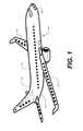
- Figure 1 is a perspective of an aircraft having a transonic shock wave mitigating system in accordance with one aspect of the present disclosure.
- Figure 2A illustrates a side view of a plasma generator in accordance with one aspect of the present disclosure.
- Figure 2B illustrates a side view a plasma generator in accordance with another aspect of the present disclosure.
- Figure 2C illustrates a side view of a plasma generator in accordance with yet another aspect of the present disclosure.
- Figure 3 illustrates a schematic diagram of a transonic shock wave mitigating system in accordance with one aspect of the present disclosure.
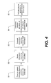
- Figure 4 illustrates a method of mitigating transonic shock in accordance with one aspect of the present disclosure.
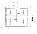
- Figure 5 illustrates a block diagram of a controller in accordance with one aspect of the present disclosure.
- Transonic shock formation may be dependent on local temperature, pressure, and velocity.
- a mechanism that can alter the flow conditions locally may cause flow to remain locally subsonic, significantly reducing adverse effects of transonic shock on vehicle performance.
- lightweight plasma heating elements integrated onto the surface of an aircraft near known transonic shock formation sites may eliminate or delay transonic shock formation.
- a system for enhancing operations of an aircraft 100 may include a plasma generator 102, a sensor 104, a controller 106 (shown in Figure 3 ), and a power source 108 (shown in Figure 3 ).
- the sensor 104 may sense information regarding a transonic flight condition and transmit the information regarding the transonic flight condition to the controller 106.
- the information sensed by the sensor 104 may include any number of variables, such as speed, altitude, temperature, angle of attack, attitude, or any other indicator that the aircraft 100 is approaching transonic or supersonic flight.
- the controller 106 may activate the plasma generator 102 in response to the information transmitted from the sensor 104 regarding the transonic flight condition.
- the activation of the plasma generator 102 may reduce the intensity of, modify the location of, or otherwise mitigate a transonic shock wave.
- activation of the plasma generator 102 may include providing power from a power source 108 to the plasma generator 102.
- Activation of the plasma generator 102 may include a binary function, such as turning the plasma generator 102 on or off.
- activation of the plasma generator 102 may include a variable function, such as adjusting the intensity of the energy provided by the plasma generator 102.
- the plasma generator 102 may be any of a number of different types of units for generating heat via plasma and/or providing a layer of weakly ionized plasma 103.
- the local speed of sound may be locally altered at the plasma generator 102, allowing for changes in strength, and location of a transonic shock wave under particular flight conditions.
- the plasma generator 102 may be any source of plasma 103, such as a set of electrodes 105 (illustrated in Figure 2a ) that receive power from the power source 108 and ignite or arc when the voltage reaches a threshold value.
- One of the set of electrodes 105 may communicate with a ground connection 107.
- Plasma generator examples may use a single electrode 109 (illustrated in Figure 2b ), or may include, but are not limited to inductively coupled radio frequency discharge, and capacitively coupled radio frequency discharge.
- the electric current flowing through the plasma may result in Joule dissipation inducing a local heating to the surrounding air, changing the local temperature and pressure conditions.
- Such flowfield change may increase the local sonic speed, effectively reducing the local Mach number to a subsonic regime and eliminating the transonic shock at a particular transonic condition.
- the plasma generator 102 may thus mitigate transonic shock or shocks, while being electronically controlled and driven, without moving parts.
- the plasma generator 102 may be on an exterior 110 of the aircraft 100.
- the plasma generator 102 may be flush with an exterior surface 112 of the aircraft 100 (as illustrated in Figures 2a and 2b ). Alternatively, the plasma generator 102 may be recessed in the exterior surface 112 of the aircraft 100 (as illustrated in Figure 2c ). Referring back to Figure 1 , depending on the particular aircraft 100, the particular expected flight conditions, and other variables, the plasma generator 102 may sit on a wing 114 of the aircraft 100, on the fuselage 116 of the aircraft 100, or elsewhere. The plasma generator 102 may be adaptive, requiring use only when transonic shock wave formation conditions are present, conserving power and reducing life cycle cost of the plasma generator 102. In some aspects, one or more additional plasma generators may be used in conjunction with the plasma generator 102.
- the use of multiple switchable plasma generators may enable adaptation of the individual plasma generators to different flight conditions, thus making the system tunable within a broad range of flight conditions.
- the additional plasma generators may be similar or even identical to the plasma generator 102.
- the various plasma generators may be grouped in clusters, and may be activated either individually, or the plasma generators in a given cluster may be activated together. Thus, any number of plasma generators may be used in any of a variety of configurations to mitigate a transonic shock wave or otherwise enhance operations of the aircraft 100.
- the sensor 104 may be configured to sense and transmit information regarding at least one transonic flight condition, such as speed, altitude, temperature, angle of attack, attitude, etc. In some aspects, the sensor 104 may be configured to sense multiple transonic flight conditions, either simultaneously, or in turn. In other aspects, the sensor 104 may sense only a single unique transonic flight condition.
- the sensor 104 may be part of preexisting systems of the aircraft 100, or the sensor 104 may be used primarily in conjunction with the plasma generator 102. The sensor 104 may be inside the aircraft 100, outside or on the exterior 110 of the aircraft 100, or elsewhere. In some aspects, one or more additional sensors may be used in conjunction with the sensor 104.
- the additional sensors may be similar or even identical to the sensor 104, and may thusly be configured to sense and transmit information regarding one or more transonic flight conditions. Thus, any number of sensors may be used to sense and transmit any of a number of flight variables useful in enhancing operations of the aircraft 100.
- the controller 106 may be configured to activate the plasma generator 102 in response to information transmitted from the sensor 104 regarding the transonic flight condition.
- the controller 106 may be configured to process information from the sensor 104 to determine whether activation of the plasma generator 102 would mitigate a transonic shock wave or otherwise enhance operations of the aircraft 100. If the controller 106 determines that activation of the plasma generator 102 would mitigate a transonic shock wave, the controller 106 may transmit a signal to the power source 108 to provide power to the plasma generator 102.
- the controller 106 may be configured to process the information from the different sensors 104, to determine the flowfield conditions around the aircraft 100.
- the controller 106 may be configured to determine the optimal plasma generation condition that will provide the following: mitigated transonic shock wave, improved aerodynamic efficiency, reduced noise, allowance for overspeed operations.
- the benefits to the aircraft 100 may include improved fuel efficiency, improved range, a larger payload capacity and improved lift to drag ratio.
- the enhanced condition may include a configuration that focuses on a particular optimal plasma generation condition to achieve a single benefit with little or even no emphasis on the others.
- the controller 106 may be configured to determine whether each plasma generator would be activated in the optimal configuration, and may activate only those plasma generators that would be activated in the optimal configuration, while de-activating those plasma generators that would be de-activated in the optimal configuration. Depending on the number and configuration of plasma generators, the controller 106 may be configured to activate the plasma generators independently of one another and/or in groups or clusters. Such clusters may be associated with different portions of the aircraft 100, such as various portions of the wing 114, or fuselage 116. Further, the controller 106 may have error correction functionality, allowing the controller 106 to filter information from multiple sensors to determine whether some sensors are unreliable. The controller 106 may also include a feedback loop to analyze which transonic flight conditions are most closely associated with enhancing flight operations.
- the power source 108 may be energy source configured to provide power to the plasma generator 102.
- the power source 108 may be either an alternating current (AC) or a direct current (DC) source.
- the power source 108 may be an auxiliary power source of the aircraft 100.
- the power source 108 may be the primary power source of the aircraft 100.
- the power source 108 may provide power in a binary manner, to turn the plasma generator 102 "on” or "off.”
- the power source may provide variable or adjustable voltage or current, to allow the plasma generator 102 to have a variable output. Wiring may run through the interior of the wing 114 and may connect the power source 108 to the plasma generator 102.
- the aircraft 100 may be any kind of aircraft, including, but not limited to transport vehicles, unmanned aircraft, rockets, helicopters, and the like.
- a system including various elements may be provided.
- the system may include the plasma generator 102 on an exterior 110 of the aircraft 100, the sensor 104 configured to sense and transmit information regarding a transonic flight condition, and the controller 106 configured to activate the plasma generator 102 in response to information transmitted from the sensor 104 regarding the transonic flight condition.
- the system may also include the power source 108 configured to provide power to the plasma generator 102.
- the sensor 104 may sense the information regarding the transonic flight condition, such as speed, altitude, temperature, angle of attack, attitude, etc.
- the sensor 104 may transmit the information regarding the transonic flight information to the controller 106.
- the controller 106 may determine, based on the information regarding the transonic flight condition, whether activation of the plasma generator 102 will mitigate a transonic shock wave.
- the controller 106 activates the plasma generator 102, to mitigate the transonic shock wave.
- Activation of the plasma generator 102 may involve transmitting a signal from the controller 106 to the power source 108 to provide power to the plasma generator 102. The process may be repeated dynamically, allowing for in-flight adjustment, as conditions change. Because the system can be electrically controlled and adaptively switched in real-time, operations of the aircraft 100 may be enhanced by quickly tuning the adaptive system in response to current flight conditions to modify wing incidence, reduce fuel burn, or otherwise enhance operations.
- the controller 106 may simultaneously or serially communicate with each.
- the steps of sensing and transmitting may include sensing with any, some, or all sensors, transmitting with any, some, or all sensors, and transmitting to any, some, or all plasma generators.
- the information transmitted may vary depending on the components used and the variables measured.
- methods for enhancing operations of the aircraft 100 also involve a determination by the controller 106 of an optimal configuration.
- the optimal configuration may be a transonic shock wave mitigating configuration, optimizing the mitigation of a transonic shock wave.
- a balanced condition may be desirable that simultaneously mitigates a transonic shock wave, while also enhancing flight operations in other ways.
- it may be desirable to mitigate, but not eliminate, a transonic shock wave while improving aircraft 100 lift to drag ratio (i.e., a fuel efficiency optimizing configuration).
- the optimal configuration may set a minimum threshold for transonic shock wave mitigation and improve lift to drag ratio, or vice versa.
- the controller 106 may calculate the optimal configuration, based on variables or other information relating to the optimization. Once the controller 106 determines that the plasma generator 102 is activated in the optimal configuration, the controller 106 may activate the plasma generator 102 such that the operation approaches the optimal condition.
- FIG. 5 is a block diagram illustrating components of the controller 106, in accordance with various aspects of the subject disclosure.
- the controller 106 may comprise a processor module 118, a storage module 120, an input/output (I/O) module 122, a memory module 124, and a bus 126.
- the bus 126 may be any suitable communication mechanism for communicating information.
- the processor module 118, storage module 120, I/O module 122, and memory module 124 may be coupled with bus 126 for communicating information between any of the modules of the controller 106 and/or information between any module of the controller 106 and a device external to the controller 106.
- information communicated between any of the modules of the controller 106 may include instructions and/or data.
- the bus 126 may be a universal serial bus.
- the processor module 118 may comprise one or more processors, where each processor may perform different functions or execute different instructions and/or processes. For example, one or more processors may execute instructions for calculating an optimized condition, and one or more processors may execute instructions for input/output functions.
- the memory module 124 may be random access memory ("RAM") or other dynamic storage devices for storing information and instructions to be executed by the processor module 118.
- the memory module 124 may also be used for storing temporary variables or other intermediate information during execution of instructions by the processor 118.
- the memory module 124 may comprise battery-powered static RAM, which stores information without requiring power to maintain the stored information.
- the storage module 120 may be a magnetic disk or optical disk and may also store information and instructions.
- the storage module 120 may comprise hard disk storage or electronic memory storage (e.g., flash memory).
- the memory module 124 and the storage module 120 are both a machine-readable medium.
- the controller 106 may be coupled via the I/O module 122 to a user interface.
- the user interface may include, for example, a keyboard or a mouse coupled to the controller 106 via the I/O module 122 for communicating information and command selections to the processor module 118.
- the controller 106 may be just an on and off switch to turn on or off the plasma generation system, giving the crew of the aircraft 100 the flexibility to employ the plasma generation system.
- the processor module 118 may execute one or more sequences of instructions contained in the memory module 124 and/or the storage module 120.
- instructions may be read into the memory module 124 from another machine-readable medium, such as the storage module 120.
- instructions may be read directly into the memory module 124 from the I/O module 122.
- Execution of the sequences of instructions contained in the memory module 124 and/or the storage module 120 may be stored in the memory module 124 and/or the storage module 120 as one or more sequences of instructions.
- Information may be communicated from the processor module 118 to the memory module 124 and/or the storage module 120 via the bus 126 for storage. In some aspects, the information may be communicated from the processor module 118, the memory module 124, and/or the storage module 120 to the I/O module 122 via the bus 126. The information may then be communicated from the I/O module 122.
- processors in a multi-processing arrangement may also be employed to execute the sequences of instructions contained in the memory module 124 and/or the storage module 120.
- hard-wired circuitry may be used in place of or in combination with software instructions to implement various aspects of the subject disclosure.
- aspects of the subject disclosure are not limited to any specific combination of hardware circuitry and software.
- machine-readable medium refers to any medium that participates in providing instructions to the processor module 118 for execution. Such a medium may take many forms, including, but not limited to, non-volatile media, volatile media, and transmission media.
- Non-volatile media include, for example, optical or magnetic disks, such as the storage module 120.
- Volatile media include dynamic memory, such as the memory module 124.
- Machine-readable media or computer-readable media include, for example, floppy disk, a flexible disk, hard disk, magnetic tape, any other magnetic medium, a CD-ROM, DVD, any other optical medium, punch cards, paper tape, any other physical mediums with patterns of holes, a RAM, a PROM, an EPROM, a FLASH EPROM, any other memory chip or cartridge, or any other medium from which a processor can read.
- the use of the plasma generator 102 may allow an incidence line of a transonic shock wave to be moved, allowing for more optimal for flight operations. Simultaneously, the plasma generator 102 may allow for a reduction in intensity of the transonic shock wave. The combination of intensity reduction and movement of the incidence line of the transonic shock wave may improve aerodynamic characteristics. Thus, it is believed that the use of the plasma generator 102 may improve the lift to drag ratio in a variety either by improving the lift, reducing the drag, or both.
- the systems described herein may be integrally formed in the aircraft 100, or may be retrofitted into existing transport platforms and become cost effective over a very short interval of operation. Power requirements may be low, on the magnitude of a few kilowatts, such that the systems described herein are lightweight, fast responding, tunable, highly adaptable to flight conditions, with a low drag profile.
- a phrase such as an "aspect” does not imply that such aspect is essential to the subject technology or that such aspect applies to all configurations of the subject technology.
- a disclosure relating to an aspect may apply to all configurations, or one or more configurations.
- a phrase such as an aspect may refer to one or more aspects and vice versa.
- a phrase such as an "embodiment” does not imply that such embodiment is essential to the subject technology or that such embodiment applies to all configurations of the subject technology.
- a disclosure relating to an embodiment may apply to all embodiments, or one or more embodiments.
- a phrase such an embodiment may refer to one or more embodiments and vice versa.
Landscapes
- Engineering & Computer Science (AREA)
- Aviation & Aerospace Engineering (AREA)
- Plasma Technology (AREA)
Abstract
Description
- Not Applicable.
- The present invention generally relates to transonic shock wave mitigation and, in particular, relates to the use of plasma generators to mitigate the formation of transonic shock wave in an aircraft.
- Aerodynamicists are keenly aware of the dramatic drag rise associated with transonic flight. A limitation in transonic flight operations is the localized transonic shock formation due to surface flows approaching sonic speeds. Typically, a dramatic drag increase, termed "drag rise" is associated with these localized transonic shock formations. The drag rise results from the transonic shock induced boundary layer separation and increased pressure drag. For high-speed aircraft, such as transport aircraft, this dramatic drag rise may become a limiting barrier for optimal cruise performance. This is especially true if the engine's optimal fuel bum rate is beyond the drag rise Mach number, termed "drag divergence Mach number." Some attempts to resolve this limitation have involved either oversizing the aircraft to carry extra fuel to compensate for the drag, or oversizing the engines to counter the increased drag. However, engine technology may not be adequate to provide the thrust to counter the associated drag rise in a cost-effective manner, and resulting vehicles are either non-optimal, or costly to operate. Other attempts to mitigate drag have included providing area ruling and anti-shock bodies. The principle of drag reduction via a smooth cross-sectional area transition from the vehicle nose to tail may be complex and/or costly in terms of weight impact and off-design skin friction drag increases.
- The following presents a simplified summary of one or more embodiments in order to provide a basic understanding of such embodiments. This summary is not an extensive overview of all contemplated embodiments, and is intended to neither identify key or critical elements of all embodiments nor delineate the scope of any or all embodiments. Its sole purpose is to present some concepts of one or more embodiments in a simplified form as a prelude to the more detailed description that is presented later.
- The present disclosure provides systems and methods for enhancing operations of an aircraft. The system may include a plasma generator, a sensor, and a controller. The plasma generator may be positioned on an exterior of the aircraft such that it can provide localized heating thereon. The sensor may be configured to sense and transmit a variety of information regarding a transonic flight condition such as speed to the controller. The controller may be configured to activate the plasma generator in response to information from the sensor, so as to mitigate a transonic shock wave through localized heating.
- Additional features and advantages of the subject technology will be set forth in the description below, and in part will be apparent from the description, or may be learned by practice of the subject technology. The advantages of the subject technology will be realized and attained by the structure particularly pointed out in the written description and claims hereof as well as the appended drawings.
- It is to be understood that both the foregoing general description and the following detailed description are exemplary and explanatory and are intended to provide further explanation of the invention as claimed.
- The accompanying drawings, which are included to provide further understanding of the subject technology and are incorporated in and constitute a part of this specification, illustrate aspects of the subject technology and together with the description serve to explain the principles of the subject technology.
-
Figure 1 is a perspective of an aircraft having a transonic shock wave mitigating system in accordance with one aspect of the present disclosure. -
Figure 2A illustrates a side view of a plasma generator in accordance with one aspect of the present disclosure. -
Figure 2B illustrates a side view a plasma generator in accordance with another aspect of the present disclosure. -
Figure 2C illustrates a side view of a plasma generator in accordance with yet another aspect of the present disclosure. -
Figure 3 illustrates a schematic diagram of a transonic shock wave mitigating system in accordance with one aspect of the present disclosure. -
Figure 4 illustrates a method of mitigating transonic shock in accordance with one aspect of the present disclosure. -
Figure 5 illustrates a block diagram of a controller in accordance with one aspect of the present disclosure. - In the following detailed description, numerous specific details are set forth to provide a full understanding of the subject technology. It will be apparent, however, to one ordinarily skilled in the art that the subject technology may be practiced without some of these specific details. In other instances, well-known structures and techniques have not been shown in detail so as not to obscure the subject technology.
- Transonic shock formation may be dependent on local temperature, pressure, and velocity. Thus, a mechanism that can alter the flow conditions locally may cause flow to remain locally subsonic, significantly reducing adverse effects of transonic shock on vehicle performance. More particularly, lightweight plasma heating elements integrated onto the surface of an aircraft near known transonic shock formation sites may eliminate or delay transonic shock formation.
- Referring to
Figure 1 , a system for enhancing operations of anaircraft 100 may include aplasma generator 102, asensor 104, a controller 106 (shown inFigure 3 ), and a power source 108 (shown inFigure 3 ). Thesensor 104 may sense information regarding a transonic flight condition and transmit the information regarding the transonic flight condition to thecontroller 106. The information sensed by thesensor 104 may include any number of variables, such as speed, altitude, temperature, angle of attack, attitude, or any other indicator that theaircraft 100 is approaching transonic or supersonic flight. Upon determination that a transonic flight condition is present, thecontroller 106 may activate theplasma generator 102 in response to the information transmitted from thesensor 104 regarding the transonic flight condition. The activation of theplasma generator 102 may reduce the intensity of, modify the location of, or otherwise mitigate a transonic shock wave. In some aspects, activation of theplasma generator 102 may include providing power from apower source 108 to theplasma generator 102. Activation of theplasma generator 102 may include a binary function, such as turning theplasma generator 102 on or off. Alternatively, or additionally, activation of theplasma generator 102 may include a variable function, such as adjusting the intensity of the energy provided by theplasma generator 102. - Referring to
Figures 2a, 2b, and 2c , theplasma generator 102 may be any of a number of different types of units for generating heat via plasma and/or providing a layer of weakly ionizedplasma 103. Thus, the local speed of sound may be locally altered at theplasma generator 102, allowing for changes in strength, and location of a transonic shock wave under particular flight conditions. Theplasma generator 102 may be any source ofplasma 103, such as a set of electrodes 105 (illustrated inFigure 2a ) that receive power from thepower source 108 and ignite or arc when the voltage reaches a threshold value. One of the set ofelectrodes 105 may communicate with aground connection 107. Other plasma generator examples may use a single electrode 109 (illustrated inFigure 2b ), or may include, but are not limited to inductively coupled radio frequency discharge, and capacitively coupled radio frequency discharge. When powered, the electric current flowing through the plasma may result in Joule dissipation inducing a local heating to the surrounding air, changing the local temperature and pressure conditions. Such flowfield change may increase the local sonic speed, effectively reducing the local Mach number to a subsonic regime and eliminating the transonic shock at a particular transonic condition. Theplasma generator 102 may thus mitigate transonic shock or shocks, while being electronically controlled and driven, without moving parts. Theplasma generator 102 may be on anexterior 110 of theaircraft 100. In some aspects, theplasma generator 102 may be flush with anexterior surface 112 of the aircraft 100 (as illustrated inFigures 2a and 2b ). Alternatively, theplasma generator 102 may be recessed in theexterior surface 112 of the aircraft 100 (as illustrated inFigure 2c ). Referring back toFigure 1 , depending on theparticular aircraft 100, the particular expected flight conditions, and other variables, theplasma generator 102 may sit on awing 114 of theaircraft 100, on thefuselage 116 of theaircraft 100, or elsewhere. Theplasma generator 102 may be adaptive, requiring use only when transonic shock wave formation conditions are present, conserving power and reducing life cycle cost of theplasma generator 102. In some aspects, one or more additional plasma generators may be used in conjunction with theplasma generator 102. The use of multiple switchable plasma generators may enable adaptation of the individual plasma generators to different flight conditions, thus making the system tunable within a broad range of flight conditions. The additional plasma generators may be similar or even identical to theplasma generator 102. The various plasma generators may be grouped in clusters, and may be activated either individually, or the plasma generators in a given cluster may be activated together. Thus, any number of plasma generators may be used in any of a variety of configurations to mitigate a transonic shock wave or otherwise enhance operations of theaircraft 100. - The
sensor 104 may be configured to sense and transmit information regarding at least one transonic flight condition, such as speed, altitude, temperature, angle of attack, attitude, etc. In some aspects, thesensor 104 may be configured to sense multiple transonic flight conditions, either simultaneously, or in turn. In other aspects, thesensor 104 may sense only a single unique transonic flight condition. Thesensor 104 may be part of preexisting systems of theaircraft 100, or thesensor 104 may be used primarily in conjunction with theplasma generator 102. Thesensor 104 may be inside theaircraft 100, outside or on theexterior 110 of theaircraft 100, or elsewhere. In some aspects, one or more additional sensors may be used in conjunction with thesensor 104. The additional sensors may be similar or even identical to thesensor 104, and may thusly be configured to sense and transmit information regarding one or more transonic flight conditions. Thus, any number of sensors may be used to sense and transmit any of a number of flight variables useful in enhancing operations of theaircraft 100. - Referring now to
Figure 3 , thecontroller 106 may be configured to activate theplasma generator 102 in response to information transmitted from thesensor 104 regarding the transonic flight condition. In some aspects, thecontroller 106 may be configured to process information from thesensor 104 to determine whether activation of theplasma generator 102 would mitigate a transonic shock wave or otherwise enhance operations of theaircraft 100. If thecontroller 106 determines that activation of theplasma generator 102 would mitigate a transonic shock wave, thecontroller 106 may transmit a signal to thepower source 108 to provide power to theplasma generator 102. In some aspects, thecontroller 106 may be configured to process the information from thedifferent sensors 104, to determine the flowfield conditions around theaircraft 100. Thecontroller 106 may be configured to determine the optimal plasma generation condition that will provide the following: mitigated transonic shock wave, improved aerodynamic efficiency, reduced noise, allowance for overspeed operations. The benefits to theaircraft 100 may include improved fuel efficiency, improved range, a larger payload capacity and improved lift to drag ratio. Alternatively, the enhanced condition may include a configuration that focuses on a particular optimal plasma generation condition to achieve a single benefit with little or even no emphasis on the others. After thecontroller 106 determines whether theplasma generator 102 would be activated in the optimal condition, it may activate theplasma generator 102 to provide the optimal condition. When multiple plasma generators are present, thecontroller 106 may be configured to determine whether each plasma generator would be activated in the optimal configuration, and may activate only those plasma generators that would be activated in the optimal configuration, while de-activating those plasma generators that would be de-activated in the optimal configuration. Depending on the number and configuration of plasma generators, thecontroller 106 may be configured to activate the plasma generators independently of one another and/or in groups or clusters. Such clusters may be associated with different portions of theaircraft 100, such as various portions of thewing 114, orfuselage 116. Further, thecontroller 106 may have error correction functionality, allowing thecontroller 106 to filter information from multiple sensors to determine whether some sensors are unreliable. Thecontroller 106 may also include a feedback loop to analyze which transonic flight conditions are most closely associated with enhancing flight operations. - The
power source 108 may be energy source configured to provide power to theplasma generator 102. For example, thepower source 108 may be either an alternating current (AC) or a direct current (DC) source. In some aspects, thepower source 108 may be an auxiliary power source of theaircraft 100. In other aspects, thepower source 108 may be the primary power source of theaircraft 100. Thepower source 108 may provide power in a binary manner, to turn theplasma generator 102 "on" or "off." Alternatively, or additionally, the power source may provide variable or adjustable voltage or current, to allow theplasma generator 102 to have a variable output. Wiring may run through the interior of thewing 114 and may connect thepower source 108 to theplasma generator 102. - While shown and generally described as a winged transport vehicle, the
aircraft 100 may be any kind of aircraft, including, but not limited to transport vehicles, unmanned aircraft, rockets, helicopters, and the like. - Some methods for enhancing operations of the
aircraft 100 are illustrated inFigure 4 . At step S1, a system including various elements may be provided. The system may include theplasma generator 102 on anexterior 110 of theaircraft 100, thesensor 104 configured to sense and transmit information regarding a transonic flight condition, and thecontroller 106 configured to activate theplasma generator 102 in response to information transmitted from thesensor 104 regarding the transonic flight condition. The system may also include thepower source 108 configured to provide power to theplasma generator 102. At step S2, thesensor 104 may sense the information regarding the transonic flight condition, such as speed, altitude, temperature, angle of attack, attitude, etc. At step S3, thesensor 104 may transmit the information regarding the transonic flight information to thecontroller 106. At step S4, thecontroller 106 may determine, based on the information regarding the transonic flight condition, whether activation of theplasma generator 102 will mitigate a transonic shock wave. At step S5, upon determination that activation of theplasma generator 102 will mitigate a transonic shock wave, thecontroller 106 activates theplasma generator 102, to mitigate the transonic shock wave. Activation of theplasma generator 102 may involve transmitting a signal from thecontroller 106 to thepower source 108 to provide power to theplasma generator 102. The process may be repeated dynamically, allowing for in-flight adjustment, as conditions change. Because the system can be electrically controlled and adaptively switched in real-time, operations of theaircraft 100 may be enhanced by quickly tuning the adaptive system in response to current flight conditions to modify wing incidence, reduce fuel burn, or otherwise enhance operations. - When multiple sensors or plasma generators are utilized, the
controller 106 may simultaneously or serially communicate with each. Thus, the steps of sensing and transmitting may include sensing with any, some, or all sensors, transmitting with any, some, or all sensors, and transmitting to any, some, or all plasma generators. Likewise, the information transmitted may vary depending on the components used and the variables measured. - In some aspects, methods for enhancing operations of the
aircraft 100 also involve a determination by thecontroller 106 of an optimal configuration. The optimal configuration may be a transonic shock wave mitigating configuration, optimizing the mitigation of a transonic shock wave. However, a balanced condition may be desirable that simultaneously mitigates a transonic shock wave, while also enhancing flight operations in other ways. For example, it may be desirable to mitigate, but not eliminate, a transonic shock wave while improvingaircraft 100 lift to drag ratio (i.e., a fuel efficiency optimizing configuration). Depending on the parameters of the flight, the optimal configuration may set a minimum threshold for transonic shock wave mitigation and improve lift to drag ratio, or vice versa. Thecontroller 106 may calculate the optimal configuration, based on variables or other information relating to the optimization. Once thecontroller 106 determines that theplasma generator 102 is activated in the optimal configuration, thecontroller 106 may activate theplasma generator 102 such that the operation approaches the optimal condition. -
Figure 5 is a block diagram illustrating components of thecontroller 106, in accordance with various aspects of the subject disclosure. Thecontroller 106 may comprise aprocessor module 118, astorage module 120, an input/output (I/O)module 122, amemory module 124, and abus 126. Thebus 126 may be any suitable communication mechanism for communicating information. Theprocessor module 118,storage module 120, I/O module 122, andmemory module 124 may be coupled withbus 126 for communicating information between any of the modules of thecontroller 106 and/or information between any module of thecontroller 106 and a device external to thecontroller 106. For example, information communicated between any of the modules of thecontroller 106 may include instructions and/or data. In some aspects, thebus 126 may be a universal serial bus. - In some aspects, the
processor module 118 may comprise one or more processors, where each processor may perform different functions or execute different instructions and/or processes. For example, one or more processors may execute instructions for calculating an optimized condition, and one or more processors may execute instructions for input/output functions. - The
memory module 124 may be random access memory ("RAM") or other dynamic storage devices for storing information and instructions to be executed by theprocessor module 118. Thememory module 124 may also be used for storing temporary variables or other intermediate information during execution of instructions by theprocessor 118. In some aspects, thememory module 124 may comprise battery-powered static RAM, which stores information without requiring power to maintain the stored information. Thestorage module 120 may be a magnetic disk or optical disk and may also store information and instructions. In some aspects, thestorage module 120 may comprise hard disk storage or electronic memory storage (e.g., flash memory). In some aspects, thememory module 124 and thestorage module 120 are both a machine-readable medium. - The
controller 106 may be coupled via the I/O module 122 to a user interface. For example, the user interface may include, for example, a keyboard or a mouse coupled to thecontroller 106 via the I/O module 122 for communicating information and command selections to theprocessor module 118. In addition, in its simplest form, thecontroller 106 may be just an on and off switch to turn on or off the plasma generation system, giving the crew of theaircraft 100 the flexibility to employ the plasma generation system. - According to various aspects of the subject disclosure, methods described herein are executed by the
controller 106. Specifically, theprocessor module 118 may execute one or more sequences of instructions contained in thememory module 124 and/or thestorage module 120. In one example, instructions may be read into thememory module 124 from another machine-readable medium, such as thestorage module 120. In another example, instructions may be read directly into thememory module 124 from the I/O module 122. Execution of the sequences of instructions contained in thememory module 124 and/or thestorage module 120 may be stored in thememory module 124 and/or thestorage module 120 as one or more sequences of instructions. Information may be communicated from theprocessor module 118 to thememory module 124 and/or thestorage module 120 via thebus 126 for storage. In some aspects, the information may be communicated from theprocessor module 118, thememory module 124, and/or thestorage module 120 to the I/O module 122 via thebus 126. The information may then be communicated from the I/O module 122. - One or more processors in a multi-processing arrangement may also be employed to execute the sequences of instructions contained in the
memory module 124 and/or thestorage module 120. In some aspects, hard-wired circuitry may be used in place of or in combination with software instructions to implement various aspects of the subject disclosure. Thus, aspects of the subject disclosure are not limited to any specific combination of hardware circuitry and software. - The term "machine-readable medium," or "computer-readable medium," as used herein, refers to any medium that participates in providing instructions to the
processor module 118 for execution. Such a medium may take many forms, including, but not limited to, non-volatile media, volatile media, and transmission media. Non-volatile media include, for example, optical or magnetic disks, such as thestorage module 120. Volatile media include dynamic memory, such as thememory module 124. Common forms of machine-readable media or computer-readable media include, for example, floppy disk, a flexible disk, hard disk, magnetic tape, any other magnetic medium, a CD-ROM, DVD, any other optical medium, punch cards, paper tape, any other physical mediums with patterns of holes, a RAM, a PROM, an EPROM, a FLASH EPROM, any other memory chip or cartridge, or any other medium from which a processor can read. - Using the systems and methods described herein, the use of the
plasma generator 102 may allow an incidence line of a transonic shock wave to be moved, allowing for more optimal for flight operations. Simultaneously, theplasma generator 102 may allow for a reduction in intensity of the transonic shock wave. The combination of intensity reduction and movement of the incidence line of the transonic shock wave may improve aerodynamic characteristics. Thus, it is believed that the use of theplasma generator 102 may improve the lift to drag ratio in a variety either by improving the lift, reducing the drag, or both. - The systems described herein may be integrally formed in the
aircraft 100, or may be retrofitted into existing transport platforms and become cost effective over a very short interval of operation. Power requirements may be low, on the magnitude of a few kilowatts, such that the systems described herein are lightweight, fast responding, tunable, highly adaptable to flight conditions, with a low drag profile. - The foregoing description is provided to enable a person skilled in the art to practice the various configurations described herein. While the subject technology has been particularly described with reference to the various figures and configurations, it should be understood that these are for illustration purposes only and should not be taken as limiting the scope of the subject technology.
- There may be many other ways to implement the subject technology. Various functions and elements described herein may be partitioned differently from those shown without departing from the scope of the subject technology. Various modifications to these configurations will be readily apparent to those skilled in the art, and generic principles defined herein may be applied to other configurations. Thus, many changes and modifications may be made to the subject technology, by one having ordinary skill in the art, without departing from the scope of the subject technology.
- It is understood that the specific order or hierarchy of steps in the processes disclosed is an illustration of exemplary approaches. Based upon design preferences, it is understood that the specific order or hierarchy of steps in the processes may be rearranged. Some of the steps may be performed simultaneously. The accompanying method claims present elements of the various steps in a sample order, and are not meant to be limited to the specific order or hierarchy presented.
- A phrase such as an "aspect" does not imply that such aspect is essential to the subject technology or that such aspect applies to all configurations of the subject technology. A disclosure relating to an aspect may apply to all configurations, or one or more configurations. A phrase such as an aspect may refer to one or more aspects and vice versa. A phrase such as an "embodiment" does not imply that such embodiment is essential to the subject technology or that such embodiment applies to all configurations of the subject technology. A disclosure relating to an embodiment may apply to all embodiments, or one or more embodiments. A phrase such an embodiment may refer to one or more embodiments and vice versa.
- Furthermore, to the extent that the term "include," "have," or the like is used in the description or the claims, such term is intended to be inclusive in a manner similar to the term "comprise" as "comprise" is interpreted when employed as a transitional word in a claim.
- The word "exemplary" is used herein to mean "serving as an example, instance, or illustration." Any embodiment described herein as "exemplary" is not necessarily to be construed as preferred or advantageous over other embodiments.
- A reference to an element in the singular is not intended to mean "one and only one" unless specifically stated, but rather "one or more." All structural and functional equivalents to the elements of the various configurations described throughout this disclosure that are known or later come to be known to those of ordinary skill in the art are expressly incorporated herein by reference and intended to be encompassed by the subject technology. Moreover, nothing disclosed herein is intended to be dedicated to the public regardless of whether such disclosure is explicitly recited in the above description.
Claims (14)
- A system for enhancing operations of an aircraft, comprising:a plasma generator on an exterior of the aircraft;a sensor configured to sense and transmit information regarding a transonic flight condition; anda controller configured to activate the plasma generator in response to information transmitted from the sensor regarding the transonic flight condition, so as to mitigate a transonic shock wave.
- The system of claim 1, wherein the information regarding the transonic flight condition comprises information regarding at least one of speed, altitude, and temperature.
- The system of claim 1 or 2, wherein the plasma generator comprises a set of electrodes.
- The system of any of claims 1 to 3, comprising:a power source configured to provide power to the plasma generator;wherein the plasma generator is flush with an exterior surface of the aircraft; andwherein the controller is configured to transmit a signal to the power source to provide power to the plasma generator, only after determining, based on information transmitted from the sensor, that activation of the plasma generator would mitigate a transonic shock wave.
- The system of any of claims 1 to 4, comprising:an at least one additional plasma generator on an exterior of the aircraft;wherein the controller is configured to activate the plasma generators independently of one another; andwherein the controller is configured to activate the at least one additional plasma generator only after determining, based on information transmitted from the sensor, that activation of the at least one additional plasma generator would mitigate a transonic shock wave.
- The system of claim 5:wherein the controller is configured to determine, based on the information transmitted from the sensors, whether each plasma generator would be activated in an optimal configuration,wherein the controller is configured to activate only those plasma generators that would be activated in the optimal configuration, andwherein the optimal configuration comprises a transonic shock wave mitigating configuration and/ora fuel efficiency optimizing configuration.
- The system of any of claims 1 to 6, wherein the plasma generator is positioned on a wing of the aircraft.
- A method for enhancing operations of an aircraft, comprising:providing a system comprising:a plasma generator on an exterior of the aircraft;a sensor configured to sense and transmit information regarding a transonic flight condition; anda controller configured to activate the plasma generator in response to information transmitted from the sensor regarding the transonic flight condition;sensing, with the sensor, the information regarding the transonic flight condition;transmitting the information regarding the transonic flight condition from the sensor to the controller;determining, with the controller and based on the information regarding the transonic flight condition, whether activation of the plasma generator will mitigate a transonic shock wave; andupon determining that activation of the plasma generator will mitigate a transonic shock wave, activating the plasma generator, so as to mitigate a transonic shock wave.
- The method of claim 8, wherein the system comprises a power source configured to provide power to the plasma generator, and wherein activating the plasma generator comprises transmitting a signal from the controller to the power source to provide power to the plasma generator, upon determining that activation of the plasma generator will mitigate a transonic shock wave.
- The method of claim 8 or 9, wherein the information regarding the transonic flight condition comprises information regarding one of speed, altitude, and temperature.
- The method of any of claims 8 to 10, wherein the system comprises at least one additional plasma generator on the exterior of the aircraft, and wherein the controller is further configured to activate the at least one additional plasma generator in response to information transmitted from the sensor regarding the transonic flight condition.
- The method of claim 11, further comprising:determining, with the controller and based on the information regarding thetransonic flight condition, whether activation of the at least one additional plasma generator will mitigate a transonic shock wave; andupon determining that activation of the at least one additional plasma generator will mitigate a transonic shock wave, activating the at least one additional plasma generator, so as to mitigate a transonic shock wave.
- The method of claim 11 or 12:wherein the controller is configured to activate the plasma generators independently from one another;wherein the system comprises a power source configured to provide power to each plasma generator; andwherein activating each plasma generator comprises transmitting a signal from the controller to the power source to provide power to that plasma generator.
- The method of any of claims 11 to 13:wherein the controller is configured to determine, based on the information regarding the transonic flight condition, whether activation of each plasma generator will enhance operations in an optimal configuration;wherein the optimal configuration preferably comprises a fuel efficiency optimizing configuration;wherein information relating to the transonic flight condition comprises information relating to fuel efficiency;further preferably comprising:calculating, with the controller and using the information relating to fuel efficiency, a fuel efficiency optimizing configuration.
Applications Claiming Priority (1)
| Application Number | Priority Date | Filing Date | Title |
|---|---|---|---|
| US13/156,317 US20120312923A1 (en) | 2011-06-08 | 2011-06-08 | Mitigating transonic shock wave with plasma heating elements |
Publications (3)
| Publication Number | Publication Date |
|---|---|
| EP2532586A2 true EP2532586A2 (en) | 2012-12-12 |
| EP2532586A3 EP2532586A3 (en) | 2013-01-23 |
| EP2532586B1 EP2532586B1 (en) | 2017-11-01 |
Family
ID=46177206
Family Applications (1)
| Application Number | Title | Priority Date | Filing Date |
|---|---|---|---|
| EP12003730.4A Not-in-force EP2532586B1 (en) | 2011-06-08 | 2012-05-10 | Mitigating transonic shock wave with plasma heating elements |
Country Status (2)
| Country | Link |
|---|---|
| US (2) | US20120312923A1 (en) |
| EP (1) | EP2532586B1 (en) |
Cited By (3)
| Publication number | Priority date | Publication date | Assignee | Title |
|---|---|---|---|---|
| CN104760683A (en) * | 2015-05-04 | 2015-07-08 | 厦门大学 | Method for reducing wing shock wave resistance through zero-mass-flux jet |
| EP3170745A1 (en) * | 2015-11-10 | 2017-05-24 | The Boeing Company | Mitigating shock using plasma |
| CN108243549A (en) * | 2018-03-15 | 2018-07-03 | 哈尔滨工业大学 | Plasma Actuator with fluting ventilation device |
Families Citing this family (6)
| Publication number | Priority date | Publication date | Assignee | Title |
|---|---|---|---|---|
| US11014651B1 (en) * | 2016-06-30 | 2021-05-25 | Electric Sky Holdings, Inc. | Enhanced high-speed airfoil performance, including increased lift/drag ratio, from localized high-temperature speed of sound increases, and associated systems and methods |
| US10527074B2 (en) * | 2016-07-27 | 2020-01-07 | University Of Notre Dame Du Lac | Method and apparatus of plasma flow control for drag reduction |
| CN108665884B (en) * | 2018-04-24 | 2021-04-20 | 厦门大学 | Concave cavity noise suppression method based on rotary slotted cylinder |
| WO2021194572A2 (en) | 2019-12-09 | 2021-09-30 | Electric Sky Holdings, Inc. | Plasma propulsion systems and associated systems and methods |
| ES3054896T3 (en) * | 2023-05-23 | 2026-02-06 | Airbus Operations Slu | Aircraft lifting surface and aircraft comprising such lifting surface |
| US20240391584A1 (en) * | 2023-05-24 | 2024-11-28 | University Of Florida Research Foundation, Inc. | Counter-flow point embedded electrode for dynamic stall control |
Family Cites Families (32)
| Publication number | Priority date | Publication date | Assignee | Title |
|---|---|---|---|---|
| DE2949133C2 (en) * | 1979-12-06 | 1984-11-15 | Messerschmitt-Bölkow-Blohm GmbH, 8012 Ottobrunn | Airfoil with supercritical profiling |
| US4867396A (en) * | 1983-05-18 | 1989-09-19 | Lockheed Corporation | Micro flap trailing edge device for an aircraft wing |
| US6134959A (en) | 1998-08-17 | 2000-10-24 | Tao Of Systems Integration, Inc. | Method for detecting flow bifurcation during sonic flow conditions |
| US7121511B2 (en) | 2000-05-31 | 2006-10-17 | Kevin Kremeyer | Shock wave modification method and system |
| US6484971B2 (en) | 2000-07-24 | 2002-11-26 | Thombi Layukallo | Control of flow separation and related phenomena on aerodynamic surfaces |
| US6513754B1 (en) | 2001-09-26 | 2003-02-04 | The United States Of America As Represented By The Secretary Of The Navy | Transonic flow shockwave position stabilizer |
| US6682301B2 (en) | 2001-10-05 | 2004-01-27 | General Electric Company | Reduced shock transonic airfoil |
| US6570333B1 (en) * | 2002-01-31 | 2003-05-27 | Sandia Corporation | Method for generating surface plasma |
| US20030233931A1 (en) | 2002-06-14 | 2003-12-25 | Nemtsev Igor Z. | Synchronized photo-pulse detonation (SPD) |
| US20040011917A1 (en) | 2002-07-18 | 2004-01-22 | Saeks Richard E. | Shock wave modification via shock induced ion doping |
| US7140499B2 (en) | 2002-12-23 | 2006-11-28 | Burke Display Systems, Inc. | Forward feeding modular display rack for rounded articles |
| US6805325B1 (en) * | 2003-04-03 | 2004-10-19 | Rockwell Scientific Licensing, Llc. | Surface plasma discharge for controlling leading edge contamination and crossflow instabilities for laminar flow |
| US6905091B2 (en) | 2003-07-14 | 2005-06-14 | Supersonic Aerospace International, Llc | System and method for controlling the acoustic signature of a device |
| US7386395B1 (en) * | 2005-01-18 | 2008-06-10 | Honeywell International Inc. | Systems and methods for shock compensation utilizing an adaptive control technique algorithm |
| US7363809B2 (en) * | 2005-07-29 | 2008-04-29 | Honeywell International Inc. | Methods and systems for providing air data parameters using mass flow and pressure sensors |
| US7407131B1 (en) | 2005-11-14 | 2008-08-05 | The United States Of America As Represented By The Administrator Of The National Aeronautics And Space Administration | Method for creating an aeronautic sound shield having gas distributors arranged on the engines, wings, and nose of an aircraft |
| US7641153B2 (en) | 2005-11-21 | 2010-01-05 | The Boeing Company | Directed energy off-body heating for supersonic vehicle shockwave and sonic boom control |
| US7744039B2 (en) * | 2006-01-03 | 2010-06-29 | The Boeing Company | Systems and methods for controlling flows with electrical pulses |
| DE102006008864B4 (en) * | 2006-02-25 | 2013-08-22 | Deutsches Zentrum für Luft- und Raumfahrt e.V. | Flow surface element |
| WO2007106863A2 (en) | 2006-03-14 | 2007-09-20 | University Of Notre Dame Du Lac | Methods and apparatus for reducing noise via a plasma fairing |
| DE102006028614B4 (en) * | 2006-06-22 | 2014-02-13 | Deutsches Zentrum für Luft- und Raumfahrt e.V. | Method for operating a flow area element with plasma generation devices |
| DE102006031594A1 (en) * | 2006-07-08 | 2008-01-10 | Schaeffler Kg | Device for the variable adjustment of the timing of gas exchange valves of an internal combustion engine |
| US8006939B2 (en) * | 2006-11-22 | 2011-08-30 | Lockheed Martin Corporation | Over-wing traveling-wave axial flow plasma accelerator |
| US7988101B2 (en) * | 2007-05-25 | 2011-08-02 | The Boeing Company | Airfoil trailing edge plasma flow control apparatus and method |
| US8016247B2 (en) * | 2007-05-25 | 2011-09-13 | The Boeing Company | Plasma flow control actuator system and method |
| EP2215330B1 (en) * | 2007-10-26 | 2014-04-16 | Technion - Research & Development Foundation Ltd | Aerodynamic performance enhancement of fans using discharge plasma actuators |
| US8220753B2 (en) * | 2008-01-04 | 2012-07-17 | The Boeing Company | Systems and methods for controlling flows with pulsed discharges |
| US9446840B2 (en) * | 2008-07-01 | 2016-09-20 | The Boeing Company | Systems and methods for alleviating aircraft loads with plasma actuators |
| US8251318B2 (en) * | 2008-11-19 | 2012-08-28 | The Boeing Company | Disbanded cascaded array for generating and moving plasma clusters for active airflow control |
| US8196871B2 (en) * | 2008-11-26 | 2012-06-12 | General Electric Company | Control of shockwave-boundarylayer-interaction using MEMS plasma devices |
| US8453457B2 (en) * | 2009-08-26 | 2013-06-04 | Lockheed Martin Corporation | Nozzle plasma flow control utilizing dielectric barrier discharge plasma actuators |
| US8523115B2 (en) * | 2011-01-28 | 2013-09-03 | Lockheed Martin Corporation | System, apparatus, program product, and related methods for providing boundary layer flow control |
-
2011
- 2011-06-08 US US13/156,317 patent/US20120312923A1/en not_active Abandoned
-
2012
- 2012-05-10 EP EP12003730.4A patent/EP2532586B1/en not_active Not-in-force
-
2019
- 2019-04-11 US US16/381,825 patent/US11352126B2/en active Active
Non-Patent Citations (1)
| Title |
|---|
| None |
Cited By (6)
| Publication number | Priority date | Publication date | Assignee | Title |
|---|---|---|---|---|
| CN104760683A (en) * | 2015-05-04 | 2015-07-08 | 厦门大学 | Method for reducing wing shock wave resistance through zero-mass-flux jet |
| EP3170745A1 (en) * | 2015-11-10 | 2017-05-24 | The Boeing Company | Mitigating shock using plasma |
| US9725159B2 (en) | 2015-11-10 | 2017-08-08 | The Boeing Company | Mitigating shock using plasma |
| RU2721032C2 (en) * | 2015-11-10 | 2020-05-15 | Зе Боинг Компани | Mitigation of compression shock using plasma |
| CN108243549A (en) * | 2018-03-15 | 2018-07-03 | 哈尔滨工业大学 | Plasma Actuator with fluting ventilation device |
| CN108243549B (en) * | 2018-03-15 | 2018-10-30 | 哈尔滨工业大学 | Plasma Actuator with fluting ventilation device |
Also Published As
| Publication number | Publication date |
|---|---|
| US11352126B2 (en) | 2022-06-07 |
| US20120312923A1 (en) | 2012-12-13 |
| EP2532586A3 (en) | 2013-01-23 |
| EP2532586B1 (en) | 2017-11-01 |
| US20190241254A1 (en) | 2019-08-08 |
Similar Documents
| Publication | Publication Date | Title |
|---|---|---|
| US11352126B2 (en) | Mitigating transonic shock wave with plasma heating elements | |
| JP5483830B2 (en) | Method and system for controlling airflow over a cavity | |
| US7988101B2 (en) | Airfoil trailing edge plasma flow control apparatus and method | |
| EP2307273B1 (en) | Systems and methods for alleviating aircraft loads with plasma actuators | |
| Gad-el-Hak et al. | Flow control: fundamentals and practices | |
| US9541106B1 (en) | Plasma optimized aerostructures for efficient flow control | |
| US10358208B2 (en) | Hybrid flow control method for simple hinged flap high-lift system | |
| US20080308683A1 (en) | Controllable winglets | |
| Coder et al. | Design of a slotted, natural-laminar-flow airfoil for commercial transport applications | |
| Lorber et al. | Rotorcraft retreating blade stall control | |
| CN105143039B (en) | System and method for controlling sonic boom amplitude | |
| EP2347637A1 (en) | Disbanded cascaded array for generating and moving plasma clusters for active airflow control | |
| US20150028160A1 (en) | Wingtip for a general aviation aircraft | |
| US9725159B2 (en) | Mitigating shock using plasma | |
| Keller et al. | Numerical investigation of engine effects on a transport aircraft with circulation control | |
| CN108001669A (en) | A kind of leading edge slat noise suppressing method based on zero-net-mass-flux jet control | |
| US6854687B1 (en) | Nacelle integration with reflexed wing for sonic boom reduction | |
| CN106828933B (en) | Aerodynamic layout of a high-altitude long-endurance tandem-wing aircraft using the upper and lower dihedral angle difference | |
| CN109436293A (en) | A kind of shock wave control device | |
| CN103821800A (en) | Active vortex generator based on electromagnetic excitation | |
| US7416155B2 (en) | Canard position and dihedral for boom reduction and pitch/directional control | |
| US10204192B2 (en) | System and method for drag reduction | |
| US5458304A (en) | Disk spoiler system | |
| WO2019216990A1 (en) | Finlets for aircraft aft-body drag reduction | |
| EP3960631B1 (en) | Aircraft equipped with a distributed propulsion system having suction and pressure fans |
Legal Events
| Date | Code | Title | Description |
|---|---|---|---|
| PUAI | Public reference made under article 153(3) epc to a published international application that has entered the european phase |
Free format text: ORIGINAL CODE: 0009012 |
|
| AK | Designated contracting states |
Kind code of ref document: A2 Designated state(s): AL AT BE BG CH CY CZ DE DK EE ES FI FR GB GR HR HU IE IS IT LI LT LU LV MC MK MT NL NO PL PT RO RS SE SI SK SM TR |
|
| AX | Request for extension of the european patent |
Extension state: BA ME |
|
| PUAL | Search report despatched |
Free format text: ORIGINAL CODE: 0009013 |
|
| AK | Designated contracting states |
Kind code of ref document: A3 Designated state(s): AL AT BE BG CH CY CZ DE DK EE ES FI FR GB GR HR HU IE IS IT LI LT LU LV MC MK MT NL NO PL PT RO RS SE SI SK SM TR |
|
| AX | Request for extension of the european patent |
Extension state: BA ME |
|
| RIC1 | Information provided on ipc code assigned before grant |
Ipc: B64C 23/00 20060101AFI20121214BHEP |
|
| 17P | Request for examination filed |
Effective date: 20130723 |
|
| RBV | Designated contracting states (corrected) |
Designated state(s): AL AT BE BG CH CY CZ DE DK EE ES FI FR GB GR HR HU IE IS IT LI LT LU LV MC MK MT NL NO PL PT RO RS SE SI SK SM TR |
|
| 17Q | First examination report despatched |
Effective date: 20160713 |
|
| GRAP | Despatch of communication of intention to grant a patent |
Free format text: ORIGINAL CODE: EPIDOSNIGR1 |
|
| INTG | Intention to grant announced |
Effective date: 20170517 |
|
| GRAS | Grant fee paid |
Free format text: ORIGINAL CODE: EPIDOSNIGR3 |
|
| GRAA | (expected) grant |
Free format text: ORIGINAL CODE: 0009210 |
|
| AK | Designated contracting states |
Kind code of ref document: B1 Designated state(s): AL AT BE BG CH CY CZ DE DK EE ES FI FR GB GR HR HU IE IS IT LI LT LU LV MC MK MT NL NO PL PT RO RS SE SI SK SM TR |
|
| REG | Reference to a national code |
Ref country code: GB Ref legal event code: FG4D |
|
| REG | Reference to a national code |
Ref country code: CH Ref legal event code: EP Ref country code: AT Ref legal event code: REF Ref document number: 941755 Country of ref document: AT Kind code of ref document: T Effective date: 20171115 |
|
| REG | Reference to a national code |
Ref country code: IE Ref legal event code: FG4D |
|
| REG | Reference to a national code |
Ref country code: DE Ref legal event code: R096 Ref document number: 602012039103 Country of ref document: DE |
|
| REG | Reference to a national code |
Ref country code: NL Ref legal event code: MP Effective date: 20171101 |
|
| REG | Reference to a national code |
Ref country code: LT Ref legal event code: MG4D |
|
| REG | Reference to a national code |
Ref country code: AT Ref legal event code: MK05 Ref document number: 941755 Country of ref document: AT Kind code of ref document: T Effective date: 20171101 |
|
| PG25 | Lapsed in a contracting state [announced via postgrant information from national office to epo] |
Ref country code: LT Free format text: LAPSE BECAUSE OF FAILURE TO SUBMIT A TRANSLATION OF THE DESCRIPTION OR TO PAY THE FEE WITHIN THE PRESCRIBED TIME-LIMIT Effective date: 20171101 Ref country code: FI Free format text: LAPSE BECAUSE OF FAILURE TO SUBMIT A TRANSLATION OF THE DESCRIPTION OR TO PAY THE FEE WITHIN THE PRESCRIBED TIME-LIMIT Effective date: 20171101 Ref country code: NL Free format text: LAPSE BECAUSE OF FAILURE TO SUBMIT A TRANSLATION OF THE DESCRIPTION OR TO PAY THE FEE WITHIN THE PRESCRIBED TIME-LIMIT Effective date: 20171101 Ref country code: NO Free format text: LAPSE BECAUSE OF FAILURE TO SUBMIT A TRANSLATION OF THE DESCRIPTION OR TO PAY THE FEE WITHIN THE PRESCRIBED TIME-LIMIT Effective date: 20180201 Ref country code: SE Free format text: LAPSE BECAUSE OF FAILURE TO SUBMIT A TRANSLATION OF THE DESCRIPTION OR TO PAY THE FEE WITHIN THE PRESCRIBED TIME-LIMIT Effective date: 20171101 Ref country code: ES Free format text: LAPSE BECAUSE OF FAILURE TO SUBMIT A TRANSLATION OF THE DESCRIPTION OR TO PAY THE FEE WITHIN THE PRESCRIBED TIME-LIMIT Effective date: 20171101 |
|
| REG | Reference to a national code |
Ref country code: FR Ref legal event code: PLFP Year of fee payment: 7 |
|
| PG25 | Lapsed in a contracting state [announced via postgrant information from national office to epo] |
Ref country code: IS Free format text: LAPSE BECAUSE OF FAILURE TO SUBMIT A TRANSLATION OF THE DESCRIPTION OR TO PAY THE FEE WITHIN THE PRESCRIBED TIME-LIMIT Effective date: 20180301 Ref country code: HR Free format text: LAPSE BECAUSE OF FAILURE TO SUBMIT A TRANSLATION OF THE DESCRIPTION OR TO PAY THE FEE WITHIN THE PRESCRIBED TIME-LIMIT Effective date: 20171101 Ref country code: AT Free format text: LAPSE BECAUSE OF FAILURE TO SUBMIT A TRANSLATION OF THE DESCRIPTION OR TO PAY THE FEE WITHIN THE PRESCRIBED TIME-LIMIT Effective date: 20171101 Ref country code: RS Free format text: LAPSE BECAUSE OF FAILURE TO SUBMIT A TRANSLATION OF THE DESCRIPTION OR TO PAY THE FEE WITHIN THE PRESCRIBED TIME-LIMIT Effective date: 20171101 Ref country code: GR Free format text: LAPSE BECAUSE OF FAILURE TO SUBMIT A TRANSLATION OF THE DESCRIPTION OR TO PAY THE FEE WITHIN THE PRESCRIBED TIME-LIMIT Effective date: 20180202 Ref country code: BG Free format text: LAPSE BECAUSE OF FAILURE TO SUBMIT A TRANSLATION OF THE DESCRIPTION OR TO PAY THE FEE WITHIN THE PRESCRIBED TIME-LIMIT Effective date: 20180201 Ref country code: LV Free format text: LAPSE BECAUSE OF FAILURE TO SUBMIT A TRANSLATION OF THE DESCRIPTION OR TO PAY THE FEE WITHIN THE PRESCRIBED TIME-LIMIT Effective date: 20171101 |
|
| PG25 | Lapsed in a contracting state [announced via postgrant information from national office to epo] |
Ref country code: SK Free format text: LAPSE BECAUSE OF FAILURE TO SUBMIT A TRANSLATION OF THE DESCRIPTION OR TO PAY THE FEE WITHIN THE PRESCRIBED TIME-LIMIT Effective date: 20171101 Ref country code: DK Free format text: LAPSE BECAUSE OF FAILURE TO SUBMIT A TRANSLATION OF THE DESCRIPTION OR TO PAY THE FEE WITHIN THE PRESCRIBED TIME-LIMIT Effective date: 20171101 Ref country code: CZ Free format text: LAPSE BECAUSE OF FAILURE TO SUBMIT A TRANSLATION OF THE DESCRIPTION OR TO PAY THE FEE WITHIN THE PRESCRIBED TIME-LIMIT Effective date: 20171101 Ref country code: EE Free format text: LAPSE BECAUSE OF FAILURE TO SUBMIT A TRANSLATION OF THE DESCRIPTION OR TO PAY THE FEE WITHIN THE PRESCRIBED TIME-LIMIT Effective date: 20171101 Ref country code: CY Free format text: LAPSE BECAUSE OF FAILURE TO SUBMIT A TRANSLATION OF THE DESCRIPTION OR TO PAY THE FEE WITHIN THE PRESCRIBED TIME-LIMIT Effective date: 20171101 |
|
| PGFP | Annual fee paid to national office [announced via postgrant information from national office to epo] |
Ref country code: DE Payment date: 20180529 Year of fee payment: 7 |
|
| REG | Reference to a national code |
Ref country code: DE Ref legal event code: R097 Ref document number: 602012039103 Country of ref document: DE |
|
| PG25 | Lapsed in a contracting state [announced via postgrant information from national office to epo] |
Ref country code: PL Free format text: LAPSE BECAUSE OF FAILURE TO SUBMIT A TRANSLATION OF THE DESCRIPTION OR TO PAY THE FEE WITHIN THE PRESCRIBED TIME-LIMIT Effective date: 20171101 Ref country code: SM Free format text: LAPSE BECAUSE OF FAILURE TO SUBMIT A TRANSLATION OF THE DESCRIPTION OR TO PAY THE FEE WITHIN THE PRESCRIBED TIME-LIMIT Effective date: 20171101 Ref country code: RO Free format text: LAPSE BECAUSE OF FAILURE TO SUBMIT A TRANSLATION OF THE DESCRIPTION OR TO PAY THE FEE WITHIN THE PRESCRIBED TIME-LIMIT Effective date: 20171101 |
|
| PGFP | Annual fee paid to national office [announced via postgrant information from national office to epo] |
Ref country code: IT Payment date: 20180522 Year of fee payment: 7 Ref country code: FR Payment date: 20180525 Year of fee payment: 7 |
|
| PLBE | No opposition filed within time limit |
Free format text: ORIGINAL CODE: 0009261 |
|
| STAA | Information on the status of an ep patent application or granted ep patent |
Free format text: STATUS: NO OPPOSITION FILED WITHIN TIME LIMIT |
|
| 26N | No opposition filed |
Effective date: 20180802 |
|
| PGFP | Annual fee paid to national office [announced via postgrant information from national office to epo] |
Ref country code: GB Payment date: 20180529 Year of fee payment: 7 |
|
| PG25 | Lapsed in a contracting state [announced via postgrant information from national office to epo] |
Ref country code: SI Free format text: LAPSE BECAUSE OF FAILURE TO SUBMIT A TRANSLATION OF THE DESCRIPTION OR TO PAY THE FEE WITHIN THE PRESCRIBED TIME-LIMIT Effective date: 20171101 |
|
| REG | Reference to a national code |
Ref country code: CH Ref legal event code: PL |
|
| REG | Reference to a national code |
Ref country code: BE Ref legal event code: MM Effective date: 20180531 |
|
| PG25 | Lapsed in a contracting state [announced via postgrant information from national office to epo] |
Ref country code: MC Free format text: LAPSE BECAUSE OF FAILURE TO SUBMIT A TRANSLATION OF THE DESCRIPTION OR TO PAY THE FEE WITHIN THE PRESCRIBED TIME-LIMIT Effective date: 20171101 |
|
| REG | Reference to a national code |
Ref country code: IE Ref legal event code: MM4A |
|
| PG25 | Lapsed in a contracting state [announced via postgrant information from national office to epo] |
Ref country code: LI Free format text: LAPSE BECAUSE OF NON-PAYMENT OF DUE FEES Effective date: 20180531 Ref country code: CH Free format text: LAPSE BECAUSE OF NON-PAYMENT OF DUE FEES Effective date: 20180531 |
|
| PG25 | Lapsed in a contracting state [announced via postgrant information from national office to epo] |
Ref country code: LU Free format text: LAPSE BECAUSE OF NON-PAYMENT OF DUE FEES Effective date: 20180510 |
|
| PG25 | Lapsed in a contracting state [announced via postgrant information from national office to epo] |
Ref country code: IE Free format text: LAPSE BECAUSE OF NON-PAYMENT OF DUE FEES Effective date: 20180510 |
|
| PG25 | Lapsed in a contracting state [announced via postgrant information from national office to epo] |
Ref country code: BE Free format text: LAPSE BECAUSE OF NON-PAYMENT OF DUE FEES Effective date: 20180531 |
|
| REG | Reference to a national code |
Ref country code: DE Ref legal event code: R119 Ref document number: 602012039103 Country of ref document: DE |
|
| GBPC | Gb: european patent ceased through non-payment of renewal fee |
Effective date: 20190510 |
|
| PG25 | Lapsed in a contracting state [announced via postgrant information from national office to epo] |
Ref country code: MT Free format text: LAPSE BECAUSE OF NON-PAYMENT OF DUE FEES Effective date: 20180510 |
|
| PG25 | Lapsed in a contracting state [announced via postgrant information from national office to epo] |
Ref country code: TR Free format text: LAPSE BECAUSE OF FAILURE TO SUBMIT A TRANSLATION OF THE DESCRIPTION OR TO PAY THE FEE WITHIN THE PRESCRIBED TIME-LIMIT Effective date: 20171101 |
|
| PG25 | Lapsed in a contracting state [announced via postgrant information from national office to epo] |
Ref country code: GB Free format text: LAPSE BECAUSE OF NON-PAYMENT OF DUE FEES Effective date: 20190510 Ref country code: DE Free format text: LAPSE BECAUSE OF NON-PAYMENT OF DUE FEES Effective date: 20191203 Ref country code: IT Free format text: LAPSE BECAUSE OF NON-PAYMENT OF DUE FEES Effective date: 20190510 |
|
| PG25 | Lapsed in a contracting state [announced via postgrant information from national office to epo] |
Ref country code: PT Free format text: LAPSE BECAUSE OF FAILURE TO SUBMIT A TRANSLATION OF THE DESCRIPTION OR TO PAY THE FEE WITHIN THE PRESCRIBED TIME-LIMIT Effective date: 20171101 Ref country code: HU Free format text: LAPSE BECAUSE OF FAILURE TO SUBMIT A TRANSLATION OF THE DESCRIPTION OR TO PAY THE FEE WITHIN THE PRESCRIBED TIME-LIMIT; INVALID AB INITIO Effective date: 20120510 |
|
| PG25 | Lapsed in a contracting state [announced via postgrant information from national office to epo] |
Ref country code: FR Free format text: LAPSE BECAUSE OF NON-PAYMENT OF DUE FEES Effective date: 20190531 Ref country code: MK Free format text: LAPSE BECAUSE OF NON-PAYMENT OF DUE FEES Effective date: 20171101 |
|
| PG25 | Lapsed in a contracting state [announced via postgrant information from national office to epo] |
Ref country code: AL Free format text: LAPSE BECAUSE OF FAILURE TO SUBMIT A TRANSLATION OF THE DESCRIPTION OR TO PAY THE FEE WITHIN THE PRESCRIBED TIME-LIMIT Effective date: 20171101 |