EP2532552A2 - System for controlling beam pattern of vehicle headlamp and method thereof - Google Patents
System for controlling beam pattern of vehicle headlamp and method thereof Download PDFInfo
- Publication number
- EP2532552A2 EP2532552A2 EP11179339A EP11179339A EP2532552A2 EP 2532552 A2 EP2532552 A2 EP 2532552A2 EP 11179339 A EP11179339 A EP 11179339A EP 11179339 A EP11179339 A EP 11179339A EP 2532552 A2 EP2532552 A2 EP 2532552A2
- Authority
- EP
- European Patent Office
- Prior art keywords
- mode
- vehicle
- information
- beam pattern
- determining
- Prior art date
- Legal status (The legal status is an assumption and is not a legal conclusion. Google has not performed a legal analysis and makes no representation as to the accuracy of the status listed.)
- Withdrawn
Links
- 238000000034 method Methods 0.000 title claims abstract description 17
- 230000002093 peripheral effect Effects 0.000 claims abstract description 13
- 230000001678 irradiating effect Effects 0.000 claims description 4
- 230000005540 biological transmission Effects 0.000 description 3
- 230000003044 adaptive effect Effects 0.000 description 2
- 238000013500 data storage Methods 0.000 description 2
- 238000010586 diagram Methods 0.000 description 2
- 238000005516 engineering process Methods 0.000 description 2
- 230000003287 optical effect Effects 0.000 description 2
- 238000004891 communication Methods 0.000 description 1
- 230000000694 effects Effects 0.000 description 1
- 239000000446 fuel Substances 0.000 description 1
- 230000006870 function Effects 0.000 description 1
- 238000012986 modification Methods 0.000 description 1
- 230000004048 modification Effects 0.000 description 1
Images


Classifications
-
- B—PERFORMING OPERATIONS; TRANSPORTING
- B60—VEHICLES IN GENERAL
- B60Q—ARRANGEMENT OF SIGNALLING OR LIGHTING DEVICES, THE MOUNTING OR SUPPORTING THEREOF OR CIRCUITS THEREFOR, FOR VEHICLES IN GENERAL
- B60Q1/00—Arrangement of optical signalling or lighting devices, the mounting or supporting thereof or circuits therefor
- B60Q1/02—Arrangement of optical signalling or lighting devices, the mounting or supporting thereof or circuits therefor the devices being primarily intended to illuminate the way ahead or to illuminate other areas of way or environments
- B60Q1/04—Arrangement of optical signalling or lighting devices, the mounting or supporting thereof or circuits therefor the devices being primarily intended to illuminate the way ahead or to illuminate other areas of way or environments the devices being headlights
- B60Q1/14—Arrangement of optical signalling or lighting devices, the mounting or supporting thereof or circuits therefor the devices being primarily intended to illuminate the way ahead or to illuminate other areas of way or environments the devices being headlights having dimming means
-
- B—PERFORMING OPERATIONS; TRANSPORTING
- B60—VEHICLES IN GENERAL
- B60Q—ARRANGEMENT OF SIGNALLING OR LIGHTING DEVICES, THE MOUNTING OR SUPPORTING THEREOF OR CIRCUITS THEREFOR, FOR VEHICLES IN GENERAL
- B60Q1/00—Arrangement of optical signalling or lighting devices, the mounting or supporting thereof or circuits therefor
- B60Q1/02—Arrangement of optical signalling or lighting devices, the mounting or supporting thereof or circuits therefor the devices being primarily intended to illuminate the way ahead or to illuminate other areas of way or environments
- B60Q1/04—Arrangement of optical signalling or lighting devices, the mounting or supporting thereof or circuits therefor the devices being primarily intended to illuminate the way ahead or to illuminate other areas of way or environments the devices being headlights
- B60Q1/06—Arrangement of optical signalling or lighting devices, the mounting or supporting thereof or circuits therefor the devices being primarily intended to illuminate the way ahead or to illuminate other areas of way or environments the devices being headlights adjustable, e.g. remotely-controlled from inside vehicle
- B60Q1/08—Arrangement of optical signalling or lighting devices, the mounting or supporting thereof or circuits therefor the devices being primarily intended to illuminate the way ahead or to illuminate other areas of way or environments the devices being headlights adjustable, e.g. remotely-controlled from inside vehicle automatically
- B60Q1/085—Arrangement of optical signalling or lighting devices, the mounting or supporting thereof or circuits therefor the devices being primarily intended to illuminate the way ahead or to illuminate other areas of way or environments the devices being headlights adjustable, e.g. remotely-controlled from inside vehicle automatically due to special conditions, e.g. adverse weather, type of road, badly illuminated road signs or potential dangers
-
- B—PERFORMING OPERATIONS; TRANSPORTING
- B60—VEHICLES IN GENERAL
- B60Q—ARRANGEMENT OF SIGNALLING OR LIGHTING DEVICES, THE MOUNTING OR SUPPORTING THEREOF OR CIRCUITS THEREFOR, FOR VEHICLES IN GENERAL
- B60Q11/00—Arrangement of monitoring devices for devices provided for in groups B60Q1/00 - B60Q9/00
-
- B—PERFORMING OPERATIONS; TRANSPORTING
- B60—VEHICLES IN GENERAL
- B60Q—ARRANGEMENT OF SIGNALLING OR LIGHTING DEVICES, THE MOUNTING OR SUPPORTING THEREOF OR CIRCUITS THEREFOR, FOR VEHICLES IN GENERAL
- B60Q2300/00—Indexing codes for automatically adjustable headlamps or automatically dimmable headlamps
- B60Q2300/10—Indexing codes relating to particular vehicle conditions
- B60Q2300/11—Linear movements of the vehicle
- B60Q2300/112—Vehicle speed
-
- B—PERFORMING OPERATIONS; TRANSPORTING
- B60—VEHICLES IN GENERAL
- B60Q—ARRANGEMENT OF SIGNALLING OR LIGHTING DEVICES, THE MOUNTING OR SUPPORTING THEREOF OR CIRCUITS THEREFOR, FOR VEHICLES IN GENERAL
- B60Q2300/00—Indexing codes for automatically adjustable headlamps or automatically dimmable headlamps
- B60Q2300/10—Indexing codes relating to particular vehicle conditions
- B60Q2300/12—Steering parameters
- B60Q2300/122—Steering angle
-
- B—PERFORMING OPERATIONS; TRANSPORTING
- B60—VEHICLES IN GENERAL
- B60Q—ARRANGEMENT OF SIGNALLING OR LIGHTING DEVICES, THE MOUNTING OR SUPPORTING THEREOF OR CIRCUITS THEREFOR, FOR VEHICLES IN GENERAL
- B60Q2300/00—Indexing codes for automatically adjustable headlamps or automatically dimmable headlamps
- B60Q2300/30—Indexing codes relating to the vehicle environment
- B60Q2300/31—Atmospheric conditions
- B60Q2300/312—Adverse weather
-
- B—PERFORMING OPERATIONS; TRANSPORTING
- B60—VEHICLES IN GENERAL
- B60Q—ARRANGEMENT OF SIGNALLING OR LIGHTING DEVICES, THE MOUNTING OR SUPPORTING THEREOF OR CIRCUITS THEREFOR, FOR VEHICLES IN GENERAL
- B60Q2300/00—Indexing codes for automatically adjustable headlamps or automatically dimmable headlamps
- B60Q2300/30—Indexing codes relating to the vehicle environment
- B60Q2300/33—Driving situation
- B60Q2300/331—Driving situation characterised by the driving side, e.g. on the left or right hand side
-
- B—PERFORMING OPERATIONS; TRANSPORTING
- B60—VEHICLES IN GENERAL
- B60Q—ARRANGEMENT OF SIGNALLING OR LIGHTING DEVICES, THE MOUNTING OR SUPPORTING THEREOF OR CIRCUITS THEREFOR, FOR VEHICLES IN GENERAL
- B60Q2300/00—Indexing codes for automatically adjustable headlamps or automatically dimmable headlamps
- B60Q2300/30—Indexing codes relating to the vehicle environment
- B60Q2300/33—Driving situation
- B60Q2300/332—Driving situation on city roads
-
- B—PERFORMING OPERATIONS; TRANSPORTING
- B60—VEHICLES IN GENERAL
- B60Q—ARRANGEMENT OF SIGNALLING OR LIGHTING DEVICES, THE MOUNTING OR SUPPORTING THEREOF OR CIRCUITS THEREFOR, FOR VEHICLES IN GENERAL
- B60Q2300/00—Indexing codes for automatically adjustable headlamps or automatically dimmable headlamps
- B60Q2300/30—Indexing codes relating to the vehicle environment
- B60Q2300/33—Driving situation
- B60Q2300/333—Driving situation on suburban or country roads
-
- B—PERFORMING OPERATIONS; TRANSPORTING
- B60—VEHICLES IN GENERAL
- B60Q—ARRANGEMENT OF SIGNALLING OR LIGHTING DEVICES, THE MOUNTING OR SUPPORTING THEREOF OR CIRCUITS THEREFOR, FOR VEHICLES IN GENERAL
- B60Q2300/00—Indexing codes for automatically adjustable headlamps or automatically dimmable headlamps
- B60Q2300/30—Indexing codes relating to the vehicle environment
- B60Q2300/33—Driving situation
- B60Q2300/334—Driving situation on motorways
-
- B—PERFORMING OPERATIONS; TRANSPORTING
- B60—VEHICLES IN GENERAL
- B60Q—ARRANGEMENT OF SIGNALLING OR LIGHTING DEVICES, THE MOUNTING OR SUPPORTING THEREOF OR CIRCUITS THEREFOR, FOR VEHICLES IN GENERAL
- B60Q2300/00—Indexing codes for automatically adjustable headlamps or automatically dimmable headlamps
- B60Q2300/30—Indexing codes relating to the vehicle environment
- B60Q2300/33—Driving situation
- B60Q2300/336—Crossings
Definitions
- the present invention relates to a method for controlling a beam pattern of a vehicle headlamp and a method thereof, and more particularly, to a technology controlling and providing a beam pattern of a vehicle headlamp.
- a headlamp for a vehicle is widely used during raining or at night.
- An angle of the headlamp should be controlled such that light of the headlamp is prevented from being directly transferred to a vehicle coming from an opposite lane and a peripheral pedestrian side not to cause dazzling in a driver.
- the present invention has been made in view of the above problems, and provides a system for controlling a beam pattern of a headlamp for a vehicle using vehicle location information and a method thereof.
- a system for controlling a beam pattern of a vehicle headlamp includes: a headlamp outputting light according to a preset beam pattern; and a control module receiving vehicle information and traveling state information of a vehicle from a peripheral device in a vehicle, determining a traveling zone mode and a passage system mode according to the vehicle information and traveling state information of a vehicle, and setting the beam pattern corresponding to the determined result.
- the traveling zone mode includes at least one of a national road mode, a highway mode, a city mode, a corner mode, a crossroads mode, and a rain mode.
- the control module controls a beam pattern suited to a curved angle and a direction using the location information and steering information when the traveling zone mode is the corner mode.
- the passage system mode includes at least one of a left hand drive (LHD) mode and a right hand drive (RHD) mode.
- the control module sets beams pattern at a left side or a right side in the LHD mode and in the RHD mode to be opposite to each other.
- the control module includes a mode determining a traveling zone mode and a passage system mode according the location information and the traveling state information; a controller setting the beam pattern determined by at least one of an irradiating direction, irradiating brightness, and an irradiation output distance of the headlamp according to the determining result of the mode determining unit; and a vehicle information collecting information collecting the location information and the traveling state information.
- the control module includes a memory storing presetting of the beam pattern corresponding to the location information and the traveling state information, and the controller selects at least of presetting of the beam pattern.
- the traveling state information includes at least one of vehicle speed information, steering information, and weather information.
- the peripheral device in a vehicle includes a navigation terminal.
- a method for controlling a beam pattern of a vehicle headlamp includes: collecting traveling state information and vehicle location information by a control module; determining a traveling zone mode using the traveling state information and the vehicle location information by the control module; determining a passage system mode using the vehicle location information by the control module; and setting a beam pattern corresponding to the determining results by the control module.
- Determining a traveling zone mode includes determining at least one of a national road mode, a highway mode, a city mode, a corner mode, a crossroads mode, and a rain mode. Determining at least one includes controlling a beam pattern suited to a curved angle and a direction using the location information and steering information when the traveling zone mode is the corner mode. Traveling state information includes at least one of vehicle speed information, steering information, and weather information. Determining a passage system mode includes determining least one of a left hand drive (LHD) mode and a right hand drive (RHD) mode. A beams pattern in the LHD mode and a beam pattern in the RHD mode are located at a left side or a right side of a vehicle to be opposite to each other.
- LHD left hand drive
- RHD right hand drive
- the present invention has following effects. First, the present invention checks a traveling zone mode of a vehicle more exactly using location information of the vehicle to improve control efficiencies of beam patterns by traveling zone modes. Second, because the present invention may control a beam pattern of a vehicle headlamp using navigation information according to a passage system mode, accident danger may be minimized when the vehicle moves to a zone having a different passage system.
- the term "traffic means” refers to Sport Utility Vehicles (SUVs), buses, trucks, passenger cars including various commercial vehicles, motor vehicles such as watercrafts including various boats and ships or aircrafts, hybrid vehicles, electric vehicles, plug-in hybrid electric vehicles, hydrogen-powered vehicles, and vehicles using fuels other than gasoline.
- SUVs Sport Utility Vehicles
- hybrid vehicles such as watercrafts including various boats and ships or aircrafts
- electric vehicles plug-in hybrid electric vehicles
- hydrogen-powered vehicles and vehicles using fuels other than gasoline.
- the foregoing hybrid vehicle uses at least two resources (e.g., both gasoline and electric energy).
- An adaptive vehicle headlamp system checks a traveling mode (highway mode or national road) of a vehicle using vehicle speed and a change value in steering wheel angle and provides different beam patterns of a headlamp by traveling modes to provide optimal traveling conditions.
- a traveling mode of a vehicle using only the vehicle speed and a change value in a steering wheel speed
- a check success rate of a traveling mode is low.
- a beam pattern of the vehicle headlamp system should be changed according to a traffic system. A technology providing a changed beam pattern according to change in a current traffic system has not been provided.
- the traffic system is divided into a left hand drive (LHD) system and a right hand drive (RHD) according to a location of a driver's seat in a vehicle. Since a driver' seat is located at a left side in a vehicle in the LHD system, a traffic system is set such that the vehicle travels through a right lane based on a divided road.
- LHD left hand drive
- RHD right hand drive
- a traffic system is set such that the vehicle travels through a right lane based on a divided road.
- Korea, USA, Ghana, Italy, Argentina, and Germany as examples of nations using the LHD system, whereas there are United Kingdom, New Zealand, and Japan using the RHD system.
- a left angle of the headlamp is set to be lower than a right angel of the headlamp to reduce dazzling in a driver of a vehicle approaching from an opposite lane.
- the present invention control a beam pattern of a vehicle headlamp according to a travel zone mode (highway mode, city centre mode, nation road mode, crossroads mode, corner mode, and the like) and a passage system mode (LHD mode and RHD mode) using a navigation system.
- a travel zone mode highway mode, city centre mode, nation road mode, crossroads mode, corner mode, and the like
- LHD mode and RHD mode passage system mode
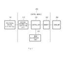
- FIG. 1 is a block diagram illustrating a configuration of a system for controlling a beam pattern of a vehicle headlamp according to an exemplary embodiment of the present invention.
- a system for controlling a beam pattern of a vehicle headlamp includes a peripheral device 100 in a vehicle, a control module 200, and a headlamp 300.
- the peripheral device 100 in a vehicle provides location information of a vehicle to the control module 200 through Controller Area Network (CAN) communication based on map data.
- the peripheral device 100 in a vehicle includes a navigation terminal.
- CAN Controller Area Network
- the headlamp irradiates light according to a beam pattern controlled by the control module 200.
- the beam pattern is determined according to at least one of change in brightness of light, change in an output distance, or change in a direction.
- the control module 200 controls a beam pattern of a vehicle headlamp 300 according to a mode (highway mode, city centre mode, national mode, crossroads mode, corner mode) travel zone where a vehicle is located and a passage system mode (LHD mode or RHD mode) using location information of the vehicle received from the peripheral device in a vehicle.
- a mode highway mode, city centre mode, national mode, crossroads mode, corner mode
- LHD mode or RHD mode passage system mode
- the LHD mode refers to a mode in which a driver' seat is located at a left side in a vehicle and the vehicle travels through a right lane based on a divided road.
- the RHD mode refers to a mode in which a driver' seat is located at a right side in the vehicle and the vehicle travels through a left lane based on a divided road.
- control module 200 includes a vehicle information collecting unit 210, a mode determining unit 220, a controller 230, and a memory 240.
- the vehicle information collecting unit 210 collects vehicle location information from the peripheral device 100, vehicle speed information from a transmission or an engine control unit (ECU)(not shown), a change value in a steering wheel angle form a steering wheel angle sensor (not shown), or weather information from a rain sensor (not shown) or a wiper sensor (not shown).
- ECU engine control unit
- the mode determining unit 220 determines a vehicle location zone mode using vehicle speed, a change value in a steering wheel angle, weather information and location information, and determines a passage system mode using vehicle location information and passage system information stored in the memory 240.
- Mode Weather information Vehicle information Change value in steering wheel angle Location information Downtown X 0 ⁇ 55KPH More than 3 times for 5 minutes Downtown General road(Natio nal road) X 55 ⁇ 85KPH Rotating angle greater than 20° General road Highway X Average greater than 85KPH Rotating angle less than 15° Highway Rain mode 0 X X X Corner mode X 5KPH Greater than 40° Slope road Crossroad s mode X 5KPH X Crossroads
- the table 1 lists reference information of vehicle information by vehicle location traveling zone modes. As illustrated in table 1, when vehicle speed is greater than an average 85KPH, a rotating angle is less than 15°, and location information is a highway, the mode determining unit 220 determines a current mode as a highway mode. The mode determining unit 220 determines a travel zone mode based on vehicle speed information, a change value in a steering wheel angle and location information, thereby increasing accuracy in determining a traveling zone mode.
- the mode determining unit 220 fetches passage system information stored in the memory 250 to check passage system information of a current vehicle location, and recognizes and determines an LHD mode and an RHD mode.
- the mode determining unit 220 recognizes a passage system information mode using passage system information previously stored in the memory 250.
- the mode determining unit 220 may fetch and use passage system information from the peripheral device 100.
- the controller 230 previously stores beam pattern information by modes in the memory 240, and then controls the headlamp 300 according to the beam pattern information by modes stored in the memory 240 according to mode information determined by the mode determining unit 220.
- the memory 240 may include an ROM, a RAM, a CD-ROM, a magnetic tape, a floppy disc, and an optical data storage device, and be implemented by carrier wave (e.g., transmission through Internet).
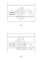
- FIG. 3a to FIG. 4f illustrate examples of beam patterns of a vehicle headlamp by modes when a vehicle travels through a right lane, respectively.
- FIG. 4a to FIG. 4f illustrate examples of beam pattern of a vehicle headlamp by modes when a vehicle travels to through a left lane, respectively.
- FIG. 3a illustrates a case where a vehicle travels to a right lane at low speed using a beam pattern corresponding to a city traveling mode in an LHD mode.
- a right side of the beam pattern in FIG. 3a is formed to be wider than a left side of the beam pattern such that a driver easily sees pedestrians along the road.
- FIG. 4a illustrates a case where a vehicle travels to a left lane at low speed. Since the road is located at a left side of the vehicle, a left side of the beam pattern in FIG. 4a is formed to be wider than a right side of the beam pattern. Accordingly, the beam pattern in FIG. 4a is formed at a left or right side of that in an LHD mode of FIG. 3a .
- FIG. 3b illustrates a beam pattern in a case of a general national travel mode in an LHD mode, and a right beam pattern is formed to be longer than a left beam pattern.
- FIG. 4b illustrates a beam pattern corresponding to a general national traveling mode in an RHD mode, which is formed at a left or right side opposite to that of FIG. 3b .
- FIG. 3c illustrates a beam pattern corresponding to a highway traveling mode in an LHD mode.
- a right side of the beam pattern in FIG. 3c is formed to be wider than a left side thereof.
- FIG. 4c illustrates a beam pattern corresponding to a highway traveling mode in an RHD mode, which is formed at a left or right side opposite to that of FIG. 3c .
- FIG. 3d illustrates a beam pattern corresponding to a rain traveling mode in an LHD mode.
- a left side of the beam pattern in FIG. 3d is formed shorter and a right side thereof is formed longer.
- FIG. 4d illustrates a beam pattern corresponding to a rain traveling mode in an RHD mode, which is formed at a left or right side of that in FIG. 3d .
- FIG. 3e illustrates a beam pattern corresponding to a corner traveling mode in an LHD mode.
- a right side of the beam pattern in FIG. 3e is formed to be longer than a left side thereof.
- FIG. 4e illustrates a beam pattern corresponding to a rain traveling mode in an RHD mode, which is formed at a left or right side opposite to that in FIG. 3e .
- FIG. 3f illustrates a beam pattern corresponding to a crossroads traveling mode in an LHD mode.
- a right side of the beam pattern is formed to be longer than a left side thereof, and an assistant lamp is turned-on at the right side thereof to be widely formed.
- FIG. 4f illustrates a beam pattern corresponding to a crossroads traveling mode in an RHD mode, which is formed at a left or right side opposite to that in FIG. 3f .
- the beam pattern is controlled suited to a curved angle and direction using vehicle location information and a change value in a steering wheel angle.
- beam patterns of a vehicle headlamp by modes when a vehicle goes to a left lane are located at a left or right side opposite to those when the vehicle goes to a left lane (LHD mode).
- the memory 240 stores collected vehicle information, passage system information by location information of a vehicle, and beam pattern information by modes of a headlamp.
- a vehicle information collecting unit 210 collects vehicle speed information, a change value in a steering wheel angle, location information of a vehicle, and weather information (S101).
- a mode determining unit 220 determines a traveling zone mode using the collected vehicle speed information, a change value in a steering wheel angle, location information of a vehicle, and weather information (S102), and determines a passage system mode using the collected location information of a vehicle (S103).
- the traveling zone mode refers to a city traveling mode, a highway mode, a general nation mode, a rain mode, a corner mode, or a crossroads mode
- the passage system mode refers to an LHD mode or an RHD mode.
- the controller 230 controls a headlamp 300 to irradiate light according to a beam pattern according to the determined traveling zone mode and passage system mode (S104).
- the present invention may determine a traveling zone mode of a vehicle for providing a beam pattern of a vehicle headlamp using vehicle speed information, weather information, a change value in a steering wheel angle, and location information to increase accuracy in determining the traveling zone mode.
- the present invention may determine a passage system mode of a traveling zone in a vehicle to provide a beam pattern rapidly corresponding to change in a passage system mode any time, thereby reduce accident danger.
- a method according to an embodiment of the present invention may be implemented as a code readable by a processor of a medium recording a program.
- a processor of a medium recording a program There are ROM, RAM, CD-ROM, magnetic tape, floppy disc, and optical data storage device as examples of a program readable medium.
- the program readable medium includes an objected implemented by a form of a carrier wave (e.g., transmission through Internet).
Landscapes
- Engineering & Computer Science (AREA)
- Mechanical Engineering (AREA)
- Lighting Device Outwards From Vehicle And Optical Signal (AREA)
Abstract
Description
- Priority to Korean patent application number
10-2011-0055829, filed on June 9, 2011 - The present invention relates to a method for controlling a beam pattern of a vehicle headlamp and a method thereof, and more particularly, to a technology controlling and providing a beam pattern of a vehicle headlamp.
- A headlamp for a vehicle is widely used during raining or at night. An angle of the headlamp should be controlled such that light of the headlamp is prevented from being directly transferred to a vehicle coming from an opposite lane and a peripheral pedestrian side not to cause dazzling in a driver.
- The present invention has been made in view of the above problems, and provides a system for controlling a beam pattern of a headlamp for a vehicle using vehicle location information and a method thereof.
- In accordance with an aspect of the present invention, a system for controlling a beam pattern of a vehicle headlamp includes: a headlamp outputting light according to a preset beam pattern; and a control module receiving vehicle information and traveling state information of a vehicle from a peripheral device in a vehicle, determining a traveling zone mode and a passage system mode according to the vehicle information and traveling state information of a vehicle, and setting the beam pattern corresponding to the determined result.
- The traveling zone mode includes at least one of a national road mode, a highway mode, a city mode, a corner mode, a crossroads mode, and a rain mode. The control module controls a beam pattern suited to a curved angle and a direction using the location information and steering information when the traveling zone mode is the corner mode. The passage system mode includes at least one of a left hand drive (LHD) mode and a right hand drive (RHD) mode. The control module sets beams pattern at a left side or a right side in the LHD mode and in the RHD mode to be opposite to each other. The control module includes a mode determining a traveling zone mode and a passage system mode according the location information and the traveling state information; a controller setting the beam pattern determined by at least one of an irradiating direction, irradiating brightness, and an irradiation output distance of the headlamp according to the determining result of the mode determining unit; and a vehicle information collecting information collecting the location information and the traveling state information. The control module includes a memory storing presetting of the beam pattern corresponding to the location information and the traveling state information, and the controller selects at least of presetting of the beam pattern. The traveling state information includes at least one of vehicle speed information, steering information, and weather information. The peripheral device in a vehicle includes a navigation terminal.
- In accordance with an aspect of the present invention, a method for controlling a beam pattern of a vehicle headlamp includes: collecting traveling state information and vehicle location information by a control module; determining a traveling zone mode using the traveling state information and the vehicle location information by the control module; determining a passage system mode using the vehicle location information by the control module; and setting a beam pattern corresponding to the determining results by the control module.
- Determining a traveling zone mode includes determining at least one of a national road mode, a highway mode, a city mode, a corner mode, a crossroads mode, and a rain mode. Determining at least one includes controlling a beam pattern suited to a curved angle and a direction using the location information and steering information when the traveling zone mode is the corner mode. Traveling state information includes at least one of vehicle speed information, steering information, and weather information. Determining a passage system mode includes determining least one of a left hand drive (LHD) mode and a right hand drive (RHD) mode. A beams pattern in the LHD mode and a beam pattern in the RHD mode are located at a left side or a right side of a vehicle to be opposite to each other.
- The present invention has following effects. First, the present invention checks a traveling zone mode of a vehicle more exactly using location information of the vehicle to improve control efficiencies of beam patterns by traveling zone modes. Second, because the present invention may control a beam pattern of a vehicle headlamp using navigation information according to a passage system mode, accident danger may be minimized when the vehicle moves to a zone having a different passage system.
- The objects, features and advantages of the present invention will be more apparent from the following detailed description in conjunction with the accompanying drawings, in which:
-
FIG. 1 is a block diagram illustrating a configuration of a system for controlling a beam pattern of a vehicle headlamp according to an exemplary embodiment of the present invention; -
FIG. 2 is a flowchart illustrating a method for controlling a beam pattern of a vehicle headlamp according to an exemplary embodiment of the present invention; -
FIG. 3a to FIG. 3f are views illustrating beam patterns of a vehicle headlamp by traveling zone modes, respectively; and -
FIG. 4a to FIG. 4f are views illustrating beam patterns of a vehicle headlamp by passage system modes, respectively. - Exemplary embodiments of the present invention are described with reference to the accompanying drawings in detail. The same reference numbers are used throughout the drawings to refer to the same or like parts. Detailed descriptions of well-known functions and structures incorporated herein may be omitted to avoid obscuring the subject matter of the present invention.
- As used herein, the term "traffic means" refers to Sport Utility Vehicles (SUVs), buses, trucks, passenger cars including various commercial vehicles, motor vehicles such as watercrafts including various boats and ships or aircrafts, hybrid vehicles, electric vehicles, plug-in hybrid electric vehicles, hydrogen-powered vehicles, and vehicles using fuels other than gasoline. In particular, the foregoing hybrid vehicle uses at least two resources (e.g., both gasoline and electric energy).
- An adaptive vehicle headlamp system checks a traveling mode (highway mode or national road) of a vehicle using vehicle speed and a change value in steering wheel angle and provides different beam patterns of a headlamp by traveling modes to provide optimal traveling conditions. However, since the adaptive vehicle headlamp system checks a traveling mode of a vehicle using only the vehicle speed and a change value in a steering wheel speed, a check success rate of a traveling mode is low. Further, a beam pattern of the vehicle headlamp system should be changed according to a traffic system. A technology providing a changed beam pattern according to change in a current traffic system has not been provided.
- That is, the traffic system is divided into a left hand drive (LHD) system and a right hand drive (RHD) according to a location of a driver's seat in a vehicle. Since a driver' seat is located at a left side in a vehicle in the LHD system, a traffic system is set such that the vehicle travels through a right lane based on a divided road.
- Since a driver' seat is located at a left side in a vehicle in the RHD system, a traffic system is set such that the vehicle travels through a right lane based on a divided road. There are Korea, USA, Ghana, Italy, Argentina, and Germany as examples of nations using the LHD system, whereas there are United Kingdom, New Zealand, and Japan using the RHD system.
- In a general, the LHD system is used, a left angle of the headlamp is set to be lower than a right angel of the headlamp to reduce dazzling in a driver of a vehicle approaching from an opposite lane.
- However, when a vehicle moves from a nation using the LHD system to a nation using the RHD system (moves from France to United Kingdom through strait of Dover), it travels a right lane and then converts the lane from the right lane to a left lane. When a beam pattern applied to the LHD system is used unchanged, dazzling may be applied to a driver of a vehicle approaching from an opposite line to cause accident danger.
- The present invention control a beam pattern of a vehicle headlamp according to a travel zone mode (highway mode, city centre mode, nation road mode, crossroads mode, corner mode, and the like) and a passage system mode (LHD mode and RHD mode) using a navigation system.
- Hereinafter, a system and a method for controlling a beam pattern of a vehicle headlamp according to an embodiment of the present invention will be described with reference to
FIG. 1 to FIG. 4f in detail.FIG. 1 is a block diagram illustrating a configuration of a system for controlling a beam pattern of a vehicle headlamp according to an exemplary embodiment of the present invention. - A system for controlling a beam pattern of a vehicle headlamp according to an embodiment of the present invention includes a
peripheral device 100 in a vehicle, acontrol module 200, and aheadlamp 300. - The
peripheral device 100 in a vehicle provides location information of a vehicle to thecontrol module 200 through Controller Area Network (CAN) communication based on map data. Theperipheral device 100 in a vehicle includes a navigation terminal. - The headlamp irradiates light according to a beam pattern controlled by the
control module 200. At this time, the beam pattern is determined according to at least one of change in brightness of light, change in an output distance, or change in a direction. - The
control module 200 controls a beam pattern of avehicle headlamp 300 according to a mode (highway mode, city centre mode, national mode, crossroads mode, corner mode) travel zone where a vehicle is located and a passage system mode (LHD mode or RHD mode) using location information of the vehicle received from the peripheral device in a vehicle. - Here, the LHD mode refers to a mode in which a driver' seat is located at a left side in a vehicle and the vehicle travels through a right lane based on a divided road. The RHD mode refers to a mode in which a driver' seat is located at a right side in the vehicle and the vehicle travels through a left lane based on a divided road.
- To do this, the
control module 200 includes a vehicleinformation collecting unit 210, amode determining unit 220, acontroller 230, and amemory 240. - The vehicle
information collecting unit 210 collects vehicle location information from theperipheral device 100, vehicle speed information from a transmission or an engine control unit (ECU)(not shown), a change value in a steering wheel angle form a steering wheel angle sensor (not shown), or weather information from a rain sensor (not shown) or a wiper sensor (not shown). - The
mode determining unit 220 determines a vehicle location zone mode using vehicle speed, a change value in a steering wheel angle, weather information and location information, and determines a passage system mode using vehicle location information and passage system information stored in thememory 240.[Table1] Mode Weather information Vehicle information Change value in steering wheel angle Location information Downtown X 0∼55KPH More than 3 times for 5 minutes Downtown General road(Natio nal road) X 55∼85KPH Rotating angle greater than 20° General road Highway X Average greater than 85KPH Rotating angle less than 15° Highway Rain mode 0 X X X Corner mode X 5KPH Greater than 40° Slope road Crossroad s mode X 5KPH X Crossroads - The table 1 lists reference information of vehicle information by vehicle location traveling zone modes. As illustrated in table 1, when vehicle speed is greater than an average 85KPH, a rotating angle is less than 15°, and location information is a highway, the
mode determining unit 220 determines a current mode as a highway mode. Themode determining unit 220 determines a travel zone mode based on vehicle speed information, a change value in a steering wheel angle and location information, thereby increasing accuracy in determining a traveling zone mode. - Further, the
mode determining unit 220 fetches passage system information stored in the memory 250 to check passage system information of a current vehicle location, and recognizes and determines an LHD mode and an RHD mode. Here, the foregoing embodiment has illustrated that themode determining unit 220 recognizes a passage system information mode using passage system information previously stored in the memory 250. However, themode determining unit 220 may fetch and use passage system information from theperipheral device 100. - The
controller 230 previously stores beam pattern information by modes in thememory 240, and then controls theheadlamp 300 according to the beam pattern information by modes stored in thememory 240 according to mode information determined by themode determining unit 220. At this time, thememory 240 may include an ROM, a RAM, a CD-ROM, a magnetic tape, a floppy disc, and an optical data storage device, and be implemented by carrier wave (e.g., transmission through Internet). - In this case, beam patterns by modes are illustrated in
FIG. 3a to FIG. 4f .FIG. 3a to FIG. 3f illustrate examples of a beam pattern of a vehicle headlamp by modes when a vehicle travels through a right lane, respectively.FIG. 4a to FIG. 4f illustrate examples of beam pattern of a vehicle headlamp by modes when a vehicle travels to through a left lane, respectively. -
FIG. 3a illustrates a case where a vehicle travels to a right lane at low speed using a beam pattern corresponding to a city traveling mode in an LHD mode. A right side of the beam pattern inFIG. 3a is formed to be wider than a left side of the beam pattern such that a driver easily sees pedestrians along the road. -
FIG. 4a illustrates a case where a vehicle travels to a left lane at low speed. Since the road is located at a left side of the vehicle, a left side of the beam pattern inFIG. 4a is formed to be wider than a right side of the beam pattern. Accordingly, the beam pattern inFIG. 4a is formed at a left or right side of that in an LHD mode ofFIG. 3a . -
FIG. 3b illustrates a beam pattern in a case of a general national travel mode in an LHD mode, and a right beam pattern is formed to be longer than a left beam pattern.FIG. 4b illustrates a beam pattern corresponding to a general national traveling mode in an RHD mode, which is formed at a left or right side opposite to that ofFIG. 3b . -
FIG. 3c illustrates a beam pattern corresponding to a highway traveling mode in an LHD mode. A right side of the beam pattern inFIG. 3c is formed to be wider than a left side thereof. -
FIG. 4c illustrates a beam pattern corresponding to a highway traveling mode in an RHD mode, which is formed at a left or right side opposite to that ofFIG. 3c . -
FIG. 3d illustrates a beam pattern corresponding to a rain traveling mode in an LHD mode. A left side of the beam pattern inFIG. 3d is formed shorter and a right side thereof is formed longer.FIG. 4d illustrates a beam pattern corresponding to a rain traveling mode in an RHD mode, which is formed at a left or right side of that inFIG. 3d . -
FIG. 3e illustrates a beam pattern corresponding to a corner traveling mode in an LHD mode. A right side of the beam pattern inFIG. 3e is formed to be longer than a left side thereof.FIG. 4e illustrates a beam pattern corresponding to a rain traveling mode in an RHD mode, which is formed at a left or right side opposite to that inFIG. 3e . -
FIG. 3f illustrates a beam pattern corresponding to a crossroads traveling mode in an LHD mode. A right side of the beam pattern is formed to be longer than a left side thereof, and an assistant lamp is turned-on at the right side thereof to be widely formed.FIG. 4f illustrates a beam pattern corresponding to a crossroads traveling mode in an RHD mode, which is formed at a left or right side opposite to that inFIG. 3f . In particular, in a case of a corner mode, the beam pattern is controlled suited to a curved angle and direction using vehicle location information and a change value in a steering wheel angle. - As illustrated previously, beam patterns of a vehicle headlamp by modes when a vehicle goes to a left lane (RHD mode) are located at a left or right side opposite to those when the vehicle goes to a left lane (LHD mode).
- At this time, although the foregoing embodiment is limited to beam patterns shown in
FIG. 3a to FIG. 3f in an LHD system, they may be variously implemented according types of vehicle. - The
memory 240 stores collected vehicle information, passage system information by location information of a vehicle, and beam pattern information by modes of a headlamp. - Hereinafter, a method for controlling a beam pattern of a vehicle headlamp will be described with reference to
FIG. 2 . - First, a vehicle
information collecting unit 210 collects vehicle speed information, a change value in a steering wheel angle, location information of a vehicle, and weather information (S101). - Next, a
mode determining unit 220 determines a traveling zone mode using the collected vehicle speed information, a change value in a steering wheel angle, location information of a vehicle, and weather information (S102), and determines a passage system mode using the collected location information of a vehicle (S103). At this time, the traveling zone mode refers to a city traveling mode, a highway mode, a general nation mode, a rain mode, a corner mode, or a crossroads mode, and the passage system mode refers to an LHD mode or an RHD mode. - Subsequently, the
controller 230 controls aheadlamp 300 to irradiate light according to a beam pattern according to the determined traveling zone mode and passage system mode (S104). - As illustrated above, the present invention may determine a traveling zone mode of a vehicle for providing a beam pattern of a vehicle headlamp using vehicle speed information, weather information, a change value in a steering wheel angle, and location information to increase accuracy in determining the traveling zone mode. Simultaneously, the present invention may determine a passage system mode of a traveling zone in a vehicle to provide a beam pattern rapidly corresponding to change in a passage system mode any time, thereby reduce accident danger.
- Further, a method according to an embodiment of the present invention may be implemented as a code readable by a processor of a medium recording a program. There are ROM, RAM, CD-ROM, magnetic tape, floppy disc, and optical data storage device as examples of a program readable medium. The program readable medium includes an objected implemented by a form of a carrier wave (e.g., transmission through Internet).
- Although exemplary embodiments of the present invention have been described in detail hereinabove, it should be clearly understood that many variations and modifications of the basic inventive concepts herein taught which may appear to those skilled in the present art will still fall within the spirit and scope of the present invention, as defined in the appended claims.
-
- 100: Peripheral device in a vehicle
- 200: Control module
- 210: Vehicle information collecting unit
- 220: Mode determining unit
- 230: Controller
- 240: Memory
- 300: Headlamp
Claims (15)
- A system for controlling a beam pattern of a vehicle headlamp, the system comprising:a headlamp outputting light according to a preset beam pattern; anda control module receiving vehicle information and traveling state information of a vehicle from a peripheral device in a vehicle, determining a traveling zone mode and a passage system mode according to the vehicle information and traveling state information of a vehicle, and setting the beam pattern corresponding to the determined result.
- The system of claim 1, wherein the traveling zone mode comprises at least one of a national road mode, a highway mode, a city mode, a corner mode, a crossroads mode, and a rain mode.
- The system of claim 2, wherein the control module controls a beam pattern suited to a curved angle and a direction using the location information and steering information when the traveling zone mode is the corner mode.
- The system of claim 1, wherein the passage system mode comprises at least one of a left hand drive (LHD) mode and a right hand drive (RHD) mode.
- The system of claim 4, wherein the control module sets beams pattern at a left side or a right side in the LHD mode and in the RHD mode to be opposite to each other.
- The system of claim 1, wherein the control module comprises:a mode determining a traveling zone mode and a passage system mode according the location information and the traveling state information;a controller setting the beam pattern determined by at least one of an irradiating direction, irradiating brightness, and an irradiation output distance of the headlamp according to the determining result of the mode determining unit; anda vehicle information collecting information collecting the location information and the traveling state information.
- The system of claim 6, wherein the control module comprises a memory storing presetting of the beam pattern corresponding to the location information and the traveling state information, and the controller selects at least of presetting of the beam pattern.
- The system of claim 6, wherein the traveling state information comprises at least one of vehicle speed information, steering information, and weather information.
- The system of claim 1, wherein the peripheral device in a vehicle comprises a navigation terminal.
- A method for controlling a beam pattern of a vehicle headlamp, the method comprising:collecting traveling state information and vehicle location information by a control module;determining a traveling zone mode using the traveling state information and the vehicle location information by the control module;determining a passage system mode using the vehicle location information by the control module; andsetting a beam pattern corresponding to the determining results by the control module.
- The method of claim 10, wherein determining a traveling zone mode comprises determining at least one of a national road mode, a highway mode, a city mode, a corner mode, a crossroads mode, and a rain mode.
- The method of claim 11, wherein determining at least one comprise controlling a beam pattern suited to a curved angle and a direction using the location information and steering information when the traveling zone mode is the corner mode.
- The method of claim 10, wherein the traveling state information comprises at least one of vehicle speed information, steering information, and weather information.
- The method of claim 10, wherein determining a passage system mode comprises determining least one of a left hand drive (LHD) mode and a right hand drive (RHD) mode.
- The method of claim 14, wherein a beams pattern in the LHD mode and a beam pattern in the RHD mode are located at a left side or a right side of a vehicle to be opposite to each other.
Applications Claiming Priority (1)
| Application Number | Priority Date | Filing Date | Title |
|---|---|---|---|
| KR1020110055829A KR20120136720A (en) | 2011-06-09 | 2011-06-09 | System for controlling beam pattern of headlamp and thereof method |
Publications (2)
| Publication Number | Publication Date |
|---|---|
| EP2532552A2 true EP2532552A2 (en) | 2012-12-12 |
| EP2532552A3 EP2532552A3 (en) | 2014-03-05 |
Family
ID=44509055
Family Applications (1)
| Application Number | Title | Priority Date | Filing Date |
|---|---|---|---|
| EP11179339.4A Withdrawn EP2532552A3 (en) | 2011-06-09 | 2011-08-30 | System for controlling beam pattern of vehicle headlamp and method thereof |
Country Status (2)
| Country | Link |
|---|---|
| EP (1) | EP2532552A3 (en) |
| KR (1) | KR20120136720A (en) |
Cited By (3)
| Publication number | Priority date | Publication date | Assignee | Title |
|---|---|---|---|---|
| WO2015086104A1 (en) * | 2013-12-11 | 2015-06-18 | Audi Ag | Method for operating a headlight for a motor vehicle |
| CN108082032A (en) * | 2018-01-30 | 2018-05-29 | 上海晨阑光电器件有限公司 | Front truck lamp control device |
| FR3104087A1 (en) * | 2019-12-09 | 2021-06-11 | Renault S.A.S | Method and control system of a motor vehicle lighting system capable of controlling the high beam according to driving conditions |
Families Citing this family (2)
| Publication number | Priority date | Publication date | Assignee | Title |
|---|---|---|---|---|
| KR102217597B1 (en) * | 2014-08-12 | 2021-02-22 | 현대모비스 주식회사 | Control apparatus and method for adaptive front lighting system |
| CN110203127A (en) * | 2019-06-18 | 2019-09-06 | 李良杰 | Intelligent automotive light |
Citations (1)
| Publication number | Priority date | Publication date | Assignee | Title |
|---|---|---|---|---|
| KR20110055829A (en) | 2009-11-20 | 2011-05-26 | (주)더페이스샵 | Cosmetic composition for acne improvement containing phytantriol and hexamidine diethionate |
Family Cites Families (6)
| Publication number | Priority date | Publication date | Assignee | Title |
|---|---|---|---|---|
| US6861809B2 (en) * | 1998-09-18 | 2005-03-01 | Gentex Corporation | Headlamp control to prevent glare |
| EP1283127A3 (en) * | 2001-08-08 | 2009-11-18 | Volkswagen Aktiengesellschaft | Method for actuating a headlight-system to generate adapted light functions |
| FR2846609B1 (en) * | 2002-10-30 | 2005-08-19 | Valeo Vision | METHOD FOR CONTROLLING THE LIGHT BEAMS EMITTED BY A LIGHTING DEVICE OF A VEHICLE AND SYSTEM FOR IMPLEMENTING SAID METHOD |
| JP2005353477A (en) * | 2004-06-11 | 2005-12-22 | Koito Mfg Co Ltd | Vehicle lighting system |
| JP5362460B2 (en) * | 2009-06-26 | 2013-12-11 | 株式会社小糸製作所 | Vehicle headlamp device |
| JP5438405B2 (en) * | 2009-07-10 | 2014-03-12 | 株式会社小糸製作所 | Vehicle headlamp device |
-
2011
- 2011-06-09 KR KR1020110055829A patent/KR20120136720A/en not_active Ceased
- 2011-08-30 EP EP11179339.4A patent/EP2532552A3/en not_active Withdrawn
Patent Citations (1)
| Publication number | Priority date | Publication date | Assignee | Title |
|---|---|---|---|---|
| KR20110055829A (en) | 2009-11-20 | 2011-05-26 | (주)더페이스샵 | Cosmetic composition for acne improvement containing phytantriol and hexamidine diethionate |
Cited By (6)
| Publication number | Priority date | Publication date | Assignee | Title |
|---|---|---|---|---|
| WO2015086104A1 (en) * | 2013-12-11 | 2015-06-18 | Audi Ag | Method for operating a headlight for a motor vehicle |
| US20160332559A1 (en) * | 2013-12-11 | 2016-11-17 | Audi Ag | Method for operating a headlight for a motor vehicle |
| US9809154B2 (en) | 2013-12-11 | 2017-11-07 | Audi Ag | Method for operating a headlight for a motor vehicle |
| CN108082032A (en) * | 2018-01-30 | 2018-05-29 | 上海晨阑光电器件有限公司 | Front truck lamp control device |
| CN108082032B (en) * | 2018-01-30 | 2023-07-21 | 上海晨阑光电器件有限公司 | Front car light control device |
| FR3104087A1 (en) * | 2019-12-09 | 2021-06-11 | Renault S.A.S | Method and control system of a motor vehicle lighting system capable of controlling the high beam according to driving conditions |
Also Published As
| Publication number | Publication date |
|---|---|
| KR20120136720A (en) | 2012-12-20 |
| EP2532552A3 (en) | 2014-03-05 |
Similar Documents
| Publication | Publication Date | Title |
|---|---|---|
| CN110614994B (en) | Control method and control system for lane changing during automatic driving of vehicle and vehicle | |
| CN112277939B (en) | Offset control system and method for avoiding front line-pressing vehicle | |
| US10655819B2 (en) | Lamp for vehicle and method for controlling the same | |
| EP3343095B1 (en) | Lamp for vehicle and method for controlling the same | |
| EP3343096A1 (en) | Lamp for vehicle and method for controlling the same | |
| EP2532552A2 (en) | System for controlling beam pattern of vehicle headlamp and method thereof | |
| CN111204340B (en) | System and method for controlling an autonomous vehicle | |
| CN104228665B (en) | A kind of control method of self-adapted car headlamp | |
| CN112406687A (en) | 'man-vehicle-road' cooperative programmable matrix headlamp system and method | |
| US11417112B2 (en) | Object sensing apparatus | |
| US11747815B2 (en) | Limiting function of a vehicle control device related to defective image | |
| CN102592442A (en) | Glare control system based on Internet of vehicles and control method of glare control system | |
| CN106530833A (en) | Automatic driving automobile intelligent lane changing system based on automobile networking and control method thereof | |
| US20180229740A1 (en) | Vehicle system, vehicle control method, and vehicle control program | |
| JP2019043378A (en) | Vehicle control system, vehicle control device and program | |
| JP7324600B2 (en) | VEHICLE CONTROL DEVICE, VEHICLE CONTROL METHOD, AND PROGRAM | |
| US20140246975A1 (en) | Vehicle headlamp control system | |
| CN112721930A (en) | Vehicle cornering deceleration planning method, system, vehicle and storage medium | |
| JP7044000B2 (en) | Vehicle control device and vehicle control method | |
| US9227659B2 (en) | Vehicle lane control using differential torque | |
| CN204136860U (en) | A kind of self-adapted car head lamp | |
| JP2017056765A (en) | Vehicle driving support device | |
| WO2024183216A1 (en) | High and low beam automatic control method and control system and vehicle having the system | |
| CN106274644A (en) | A kind of automobiles indicator lamp control method and device | |
| JP2022147742A (en) | Control device and control method for mobile body, and vehicle |
Legal Events
| Date | Code | Title | Description |
|---|---|---|---|
| PUAI | Public reference made under article 153(3) epc to a published international application that has entered the european phase |
Free format text: ORIGINAL CODE: 0009012 |
|
| AK | Designated contracting states |
Kind code of ref document: A2 Designated state(s): AL AT BE BG CH CY CZ DE DK EE ES FI FR GB GR HR HU IE IS IT LI LT LU LV MC MK MT NL NO PL PT RO RS SE SI SK SM TR |
|
| AX | Request for extension of the european patent |
Extension state: BA ME |
|
| PUAL | Search report despatched |
Free format text: ORIGINAL CODE: 0009013 |
|
| AK | Designated contracting states |
Kind code of ref document: A3 Designated state(s): AL AT BE BG CH CY CZ DE DK EE ES FI FR GB GR HR HU IE IS IT LI LT LU LV MC MK MT NL NO PL PT RO RS SE SI SK SM TR |
|
| AX | Request for extension of the european patent |
Extension state: BA ME |
|
| RIC1 | Information provided on ipc code assigned before grant |
Ipc: B60Q 1/08 20060101AFI20140130BHEP |
|
| STAA | Information on the status of an ep patent application or granted ep patent |
Free format text: STATUS: THE APPLICATION IS DEEMED TO BE WITHDRAWN |
|
| 18D | Application deemed to be withdrawn |
Effective date: 20140906 |