EP2532551A1 - Filing port structure for fuel tank - Google Patents
Filing port structure for fuel tank Download PDFInfo
- Publication number
- EP2532551A1 EP2532551A1 EP12171046A EP12171046A EP2532551A1 EP 2532551 A1 EP2532551 A1 EP 2532551A1 EP 12171046 A EP12171046 A EP 12171046A EP 12171046 A EP12171046 A EP 12171046A EP 2532551 A1 EP2532551 A1 EP 2532551A1
- Authority
- EP
- European Patent Office
- Prior art keywords
- filling port
- open
- unlocking
- close valve
- fuel
- Prior art date
- Legal status (The legal status is an assumption and is not a legal conclusion. Google has not performed a legal analysis and makes no representation as to the accuracy of the status listed.)
- Granted
Links
- 239000002828 fuel tank Substances 0.000 title claims abstract description 33
- 239000000446 fuel Substances 0.000 claims abstract description 99
- 230000014759 maintenance of location Effects 0.000 claims abstract description 40
- 230000007423 decrease Effects 0.000 claims description 2
- 230000037431 insertion Effects 0.000 description 12
- 238000003780 insertion Methods 0.000 description 12
- 230000002452 interceptive effect Effects 0.000 description 3
- 230000002093 peripheral effect Effects 0.000 description 2
- 238000006073 displacement reaction Methods 0.000 description 1
- 230000000694 effects Effects 0.000 description 1
- 239000003502 gasoline Substances 0.000 description 1
Images


Classifications
-
- B—PERFORMING OPERATIONS; TRANSPORTING
- B60—VEHICLES IN GENERAL
- B60K—ARRANGEMENT OR MOUNTING OF PROPULSION UNITS OR OF TRANSMISSIONS IN VEHICLES; ARRANGEMENT OR MOUNTING OF PLURAL DIVERSE PRIME-MOVERS IN VEHICLES; AUXILIARY DRIVES FOR VEHICLES; INSTRUMENTATION OR DASHBOARDS FOR VEHICLES; ARRANGEMENTS IN CONNECTION WITH COOLING, AIR INTAKE, GAS EXHAUST OR FUEL SUPPLY OF PROPULSION UNITS IN VEHICLES
- B60K15/00—Arrangement in connection with fuel supply of combustion engines or other fuel consuming energy converters, e.g. fuel cells; Mounting or construction of fuel tanks
- B60K15/03—Fuel tanks
-
- B—PERFORMING OPERATIONS; TRANSPORTING
- B60—VEHICLES IN GENERAL
- B60K—ARRANGEMENT OR MOUNTING OF PROPULSION UNITS OR OF TRANSMISSIONS IN VEHICLES; ARRANGEMENT OR MOUNTING OF PLURAL DIVERSE PRIME-MOVERS IN VEHICLES; AUXILIARY DRIVES FOR VEHICLES; INSTRUMENTATION OR DASHBOARDS FOR VEHICLES; ARRANGEMENTS IN CONNECTION WITH COOLING, AIR INTAKE, GAS EXHAUST OR FUEL SUPPLY OF PROPULSION UNITS IN VEHICLES
- B60K15/00—Arrangement in connection with fuel supply of combustion engines or other fuel consuming energy converters, e.g. fuel cells; Mounting or construction of fuel tanks
- B60K15/03—Fuel tanks
- B60K15/04—Tank inlets
-
- B—PERFORMING OPERATIONS; TRANSPORTING
- B60—VEHICLES IN GENERAL
- B60K—ARRANGEMENT OR MOUNTING OF PROPULSION UNITS OR OF TRANSMISSIONS IN VEHICLES; ARRANGEMENT OR MOUNTING OF PLURAL DIVERSE PRIME-MOVERS IN VEHICLES; AUXILIARY DRIVES FOR VEHICLES; INSTRUMENTATION OR DASHBOARDS FOR VEHICLES; ARRANGEMENTS IN CONNECTION WITH COOLING, AIR INTAKE, GAS EXHAUST OR FUEL SUPPLY OF PROPULSION UNITS IN VEHICLES
- B60K15/00—Arrangement in connection with fuel supply of combustion engines or other fuel consuming energy converters, e.g. fuel cells; Mounting or construction of fuel tanks
- B60K15/03—Fuel tanks
- B60K15/04—Tank inlets
- B60K2015/0458—Details of the tank inlet
- B60K2015/0483—Means to inhibit the introduction of too small or too big filler nozzles
Definitions
- the present invention relates to a filling port structure for a fuel tank.
- JP 2008-49952 A discloses a structure which includes an opening/closing member (flap valve) that is provided with a lock member which is unlocked when a lock releasing part is pressed by a fuel nozzle with a specific diameter.
- a part of the lock member protrudes into a fuel gun insertion region (inside the filling port) and may interfere with a fuel gun that is inserted into or removed from the filling port unless the lock member is held in an unlocked state.
- the present invention provides a filling port structure for a fuel tank that prevents an open/close valve from being unlocked due to pressing by a fuel gun with a diameter outside a specific range and prevents interference between a fuel gun that is inserted into or removed from the filling port and a locking member.
- the filling port structure includes a filling port member that defines a filling port into which a fuel gun for supplying fuel to a fuel tank is inserted; an open/close valve that opens and closes the filling port; a rotary member that attaches the open/close valve to the filling port member in a manner such that the open/close valve is rotatable between an open position to open the filling port and a closed position to close the filling port; a locking member that is provided in the filling port member and is movable between a locking position to lock the open/close valve in the closed position to prevent rotation of the open/close valve, and an unlocking position to unlock the open/close valve to allow the rotation of the open/close valve, wherein the locking member is located farther from a center line of the filling port member when in the unlocking position than when in the locking position; an unlocking member that moves the locking member from the locking position to the unlocking position when pressed by the fuel gun
- the open/close valve is rotatably attached to the filling port member by the rotary member. In a normal state, the filling port is closed by the open/close valve and the open/close valve is locked in the closed position by the locking member.
- the locking member is movable between the locking position to lock the open/close valve in the closed position to prevent rotation of the open/close valve and the unlocking position to unlock the open/close valve to allow rotation of the open/close valve.
- the unlocking member moves the locking member to the unlocking position when pressed by the fuel gun with the diameter in the specific range.
- the locking member unlocks the open/close valve to allow the open/close valve to rotate when in the unlocking position.
- the open/close valve is pressed by the fuel gun in this state, the open/close valve is rotated and the filling port is opened.
- the unlocking member is pressed by a fuel gun with a diameter outside the specific range, the locking member does not unlock the open/close valve and the open/close valve is not rotated. In other words, insertion of a fuel gun with a diameter outside the specific range can be prevented.
- the filling port structure for a fuel tank also includes the retention means.
- the retention means holds the locking member in the unlocking position at least when the open/close valve is in the open position.
- the locking member according to the above aspect of the present invention is located farther from the center line of the filling port member when in the unlocking position than when in the locking position. Thus, the fuel gun is prevented from interfering with the locking member when inserted into or removed from the filling port.
- the retention means may include a guide member which is located in a guiding position to guide the fuel gun toward the open/close valve when the fuel gun is inserted into the filling port and moves to a retracted position in accordance with movement of the open/close valve to the open position, and a retention member which is provided on the guide member and holds the locking member in the unlocking position by using movement of the guide member to the retracted position; and the guide member may be located farther from the fuel gun that is inserted into the filling port when in the retracted position than when in the guiding position.
- the guide member when the fuel gun is inserted into the filling port, the guide member is in the guiding position and guides the fuel gun toward the open/close valve.
- the guide member is configured to move to the retracted position as the open/close valve is moved to the open position.
- the guide member is located farther from the fuel gun that is inserted into the filling port when in the retracted position than when in the guiding position. In other words, when in the retracted position, the guide member is far from the fuel gun that is inserted into the filling port. Thus, the fuel gun is prevented from interfering with the guide member when inserted into or removed from the filling port.
- the retention member is provided on the guide member.
- the retention member holds the locking member in the unlocking position by using the movement of the guide member to the retracted position. In other words, the movement of the guide member to the retracted position can be effectively used to hold the locking member in the unlocking position.
- the locking member may include paired lock levers, and each of the paired lock levers may include an engaging portion that is provided at one end of the lock lever and that is engageable with the open/close valve to lock the open/close valve, a contacted piece that is provided at another end of the lock lever, and a rotary support part that is provided at an intermediate portion of the lock lever and that is rotatably supported on the filling port member; and the retention members may extend from the guide member and may be in contact with the respective contacted pieces to hold the lock levers in the unlocking position when the guide member is located in the retracted position.
- the lock levers are rotatable about rotary support parts that are provided at intermediate portions of the lock levers, between the locking position and the unlocking position.
- the engaging portions at the one ends of the lock levers are engaged with the open/close valve to lock the movement of the open/close valve.
- the retention members are in contact with the respective contacted pieces at the other ends of the lock levers to hold the lock levers in the unlocking position.
- the open/close valve can be held in the locked state more securely compared to the configuration in which only one lock lever is provided.
- the retention members may include retaining faces that are contactable with the respective contacted pieces to hold the lock levers in the unlocking position, and tilted faces that are continuous with the retaining faces and are tilted to guide the respective contacted pieces onto the retaining faces in accordance with movement of the guide member to the retracted position.
- the retaining faces are brought into contact with the contacted pieces to hold the lock levers in the unlocking position. Because the contacted pieces are guided onto the retaining faces by the tilted faces as the guide member is moved to the retracted position, the contacted pieces can be smoothly guided onto the retaining faces.
- the open/close valve is prevented from being unlocked due to pressing by a fuel gun with a diameter outside a specific range, and the interference between a fuel gun that is inserted into or removed from the filling port and the locking member is prevented.
- FIG 1 illustrates the external appearance of a filling port structure 12 for a fuel tank (which is hereinafter referred to simply as "filling port structure 12") according to a first embodiment of the present invention.
- a structure which does not require a cap that closes the filling port is adopted in this embodiment.
- the lower end of an inlet pipe (not shown) is connected to a fuel tank (not shown).
- the filling port structure 12 is provided at an upper part of the inlet pipe.
- the fuel tank contains gasoline in this embodiment.
- a filling port member 16 with a generally cylindrical shape is provided at an upper part of the inlet pipe. As shown also in FIG 2B and so on, a filling port 26 is defined in the filling port member 16, and a fuel gun 28 can be inserted into the filling port 26 through an opening 18 at the upper end thereof to refill the fuel tank.
- far side refers to the side in the filling port member 16, which is close to the fuel tank (right side in FIG 2B ), and when the term “near side” is simply used, it refers to the opposite side, that is, the side from which the fuel gun 28 is inserted (left side in FIG. 2B ).
- radial direction refers to a radial direction of the generally cylindrical filling port member 16.
- a flap valve 20 is provided at an upper part of the filling port member 16, in other words, at the opening 18 of the filling port 26.
- the flap valve 20 is rotatably attached to the filling port member 16 by a hinge 22 provided at an upper part of the flap valve 20.
- the flap valve 20 is rotatable between a closed position TP to close the filling port 26 (position indicated by solid lines) and an open position HP to open the filling port 26 (the position indicated by double-dot and dash lines).
- a lower part of the flap valve 20 in other words, the side opposite the side on which the hinge 22 is located, has been largely moved to the far side (right side in FIG. 2B ).
- a stopper (not shown) is provided on an interior surface of the filling port member 16 to limit the rotatable range (open position) of the flap valve 20 within a predetermined range.
- the flap valve 20 has a diameter which is larger than that of the opening 18 as a whole.
- an annular gasket 24 (not shown in FIGs. 2A and 2B and so on) is attached to an outer periphery of the flap valve 20 so that the flap valve 20 can be held in tight contact with the peripheral edge of the opening 18.
- the gasket 24 is in close contact with the peripheral edge of the opening 18 from inside of the filling port member 16 to close the opening 18 tightly.
- a flap valve spring 36 (refer to FIG. 2B ) is wound around the hinge 22.
- the flap valve spring 36 presses the flap valve 20 toward the closed position TP so that the filling port 26 cannot be opened accidentally.
- the flap valve 20 is pressed by the fuel gun 28 and moves (rotates) to the open position HP against the pressing force of the flap valve spring 36.
- paired lock levers 30 are attached to the filling port member 16.
- the lock levers 30 are curved to surround the opening 18 when the filling port member 16 is viewed from the front.
- the two lock levers 30 are located bilaterally symmetrically when the filling port member 16 is viewed from the front.
- a pivot shaft 30S is provided on a longitudinal middle portion of each lock lever 30.
- the pivot shaft 30S is one example of the rotary support part in the present invention, and the lock levers 30 are rotatably supported by the pivot shafts 30S relative to the filling port member 16 between a locking position LP that is shown in FIG. 1 and FIG. 2A and an unlocking position UP that is shown in FIG. 5 and FIG. 6A .
- a lock lever spring 32 is attached to the filling port member 16. The lock lever spring 32 presses each of the lock levers 30 toward the locking position LP.
- Each lock lever 30 has an engaging portion 30K that extends from its lower end toward the center line CL1 of the filling port member 16 when the filling port member 16 is viewed from the front thereof.
- the engaging portions 30K are located close to the center line CL1 when the lock levers 30 are in the locking position LP.
- the engaging portions 30K are engaged respectively with engaged parts 20K that are provided on the flap valve 20 when the flap valve 20 is in the closed position TP.
- This engagement rotatably locks the flap valve 20 in the closed position TP.
- the engaging portions 30K are located apart from the hinge 22.
- the flap valve 20 can be tightly held in a locked state compared to the configuration in which the engaging portions 30K are located close to the hinge 22.
- the engaging portions 30K are located relatively farther from the center line CL1 when the lock levers 30 are in the unlocking position UP (than when the lock levers 30 are in the locking position LP).
- Each lock lever 30 has a contacted portion (contacted piece) 30Q that extends upward and toward the near side from its upper end.
- the contacted portions 30Q are located apart from each other when the lock levers 30 are in the locking position LP, and are located close to each other when the lock levers 30 are in the unlocking position UP.
- the contacted portions 30Q are respectively held in contact with retaining faces 48H of retention members 48 to hold the lock levers 30 in the unlocking position UP as described later.
- Paired unlocking pieces 38 are provided in the flap valve 20.
- the paired unlocking pieces 38 are opposed to the engaging portions 30K of the lock levers 30 in a lateral direction of FIG. 2A .
- Each unlocking piece 38 is supported by a support member (not shown) in a manner such that the unlocking piece 38 is movable to the right and left in FIG. 2A .
- the unlocking pieces 38 press the engaging portions 30K of the lock levers 30 to rotate the lock levers 30 from the locking position LP to the unlocking position UP.
- each unlocking piece 38 has a tapered face 38T on its near side.
- the distance between the two tapered faces 38T is suited for a fuel gun for a fuel that should be supplied to the fuel tank (appropriate fuel).
- the unlocking pieces 38 are moved in the direction of arrows M1 (refer to FIG. 3 ).
- the lock levers 30 are moved from the locking position LP to the unlocking position UP.
- a fuel gun for a fuel that should not be supplied to the fuel tank does not contact the tapered faces 38T (a fuel gun for an inappropriate fuel may contact one of the tapered faces 38T but does not contact both the tapered faces 38T simultaneously), and at least one of the lock levers 30 are held in the locking position LP.
- a guide member 40 is provided above an insertion region SE through which the fuel gun 28 for an appropriate fuel is brought into contact with the flap valve 20.
- Guide pieces 42 are provided on right and left sides of the guide member 40.
- Each of the guide member 40 and the guide pieces 42 has a tilted guide face 40G on its near side, which guides the fuel gun 28 into the insertion region SE when the fuel gun 28 is not inserted properly into the insertion region SE toward the filling port 26.
- the guide member 40 is bent at an obtuse angle at a point between its one end 40A and another end 40C to form a bent portion 40B.
- the part of the guide member 40 on the one end 40A side from the bent portion 40B has the tilted guide face 40G, which guides the fuel gun 28 toward the flap valve 20.
- the part of the guide member 40 on the other end 40C side has a movement restricting face 40L that restricts the movement of the fuel gun 28 in a vertical direction (direction perpendicular to the arrow Al in FIG. 2B ) after the fuel gun 28 has been placed against the flap valve 20.
- a pivot shaft 52 that extends parallel to the hinge 22 is provided at a location above and on the near side of the guide member 40.
- the guide member 40 is rotatably attached at a part near the one end 40A (the near side end) to the filling port member 16 using the pivot shaft 52.
- a guide member spring 54 is attached to the pivot shaft 52.
- the guide member spring 54 presses the guide member 40 to urge the other end 40C upward.
- the other end 40C of the guide member 40 is always held in contact with the flap valve 20 by the pressing force of the guide member spring 54.
- the position where the other end 40C contacts the flap valve 20 moves (slides) upward (toward the hinge 22) as the flap valve 20 rotates from the closed position TP to the open position HP.
- the guide member 40 is rotated from a guiding position GP that is shown in FIG. 2B to a retracted position EP that is shown in FIG 6B by the pressing force of the guide member spring 54 as the flap valve 20 rotates from the closed position TP to the open position HP.
- the tilted guide face 40G of the guide member 40 is tilted toward the center of the filling port 26.
- the tilted guide face 40G guides the fuel gun 28 toward the flap valve 20, which closes the filling port 26, when the fuel gun 28 is inserted into the filling port 26 and the end of the fuel gun 28 contacts the tilted guide face 40G.
- the guide member 40 when the guide member 40 is in the retracted position EP, the entire guide member 40 is in a retraction region AE which is retracted from the insertion region SE for the fuel gun 28 as can be understood from FIG. 6B .
- the fuel gun 28 when the fuel gun 28 is inserted into the filling port 26, the fuel gun 28 and the guide member 40 do not interfere with each other.
- paired retention members 48 are provided on the reverse face of the guide member 40 (the face on the far side when the guide member 40 is in the guiding position GP).
- the retention members 48 are symmetrical with respect to the center line CL1.
- a retaining face 48H, a tilted face 48T and an introducing face 48G are formed, in this order from the bottom (the side close to the guide member 40), on each of opposing faces of the retention members 48.
- each contacted portion 30Q is in contact with the corresponding introducing face 48G or opposed to the corresponding introducing face 48G with a small gap therebetween.
- the introducing faces 48G are positioned so as to have such a positional relationship with the contacted portions 30Q.
- the retention members 48 are positioned such that the retaining faces 48H are in contact with the contacted portions 30Q to hold the contacted portions 30Q close to each other in order to hold the lock levers 30 in the unlocking position when the guide member 40 is in the retracted position EP as shown in FIG. 6B (refer to FIG. 8D ).
- the tilted faces 48T are brought into contact with the contacted portions 30Q and guide the contacted portions 30Q onto the retaining faces 48H (refer to FIGs. 8B to 8D ).
- the distance between the tilted faces 48T gradually decreases in the direction from the introducing faces 48G to the retaining faces 48H.
- the guide member 40 and the retention members 48 constitute the retention means of the present invention.
- the lock levers 30 are in the locking position.
- the contacted portions 30Q at the upper ends of the lock levers 30 are apart from each other and are in contact with the corresponding introducing faces 48G or opposed to the corresponding introducing faces 48G with a small gap therebetween.
- the fuel gun for an inappropriate fuel does not contact the tapered faces 38T of the two unlocking pieces 38 simultaneously.
- the unlocking pieces 38 are not moved to the unlocking position, and the lock levers 30 are also held in the locking position LP. Because the flap valve 20 is held in the locked state, the flap valve 20 cannot be rotated from the closed position. In other words, the fuel gun for an inappropriate fuel cannot be inserted into the filling port 26, and so-called misfueling is prevented.
- the flap valve 20 can be moved to the open position HP by further inserting the fuel gun 28 into the filling port 26. Then, the fuel gun 28 can be inserted to a prescribed position in the filling port 26 to refill the fuel tank.
- the guide member 40 is moved to the retracted position EP as shown in FIG. 6B by the pressing force of the guide member spring 54.
- the retention members 48 move upwards along with the movement of the guide member 40.
- the contacted portions 30Q may temporarily tend to move away from each other, but the tilted faces 48T of the retention members 48, which are moving upward, are brought into contact with the contacted portions 30Q.
- the tilted faces 48T further move upward, the contacted portions 30Q are guided in a direction toward each other by the tilted faces 48T (refer to FIG. 8C ).
- the engaging portions 30K of the lock levers 30 are located in the retraction region AE, in other words, outside the region through which the fuel gun 28 is insert into the filling port 26.
- the fuel gun 28 can be smoothly inserted without interference with the lock levers 30.
- the flap valve 20 When the fuel gun 28 is removed from the filling port 26, the flap valve 20 is in the open position HP, or the flap valve 20 is somewhere between the open position HP and the closed position TP, and the guide member 40 is in the retracted position EP as can be understood from FIG. 6B .
- the retaining faces 48H of the retention members 48 are in contact with the contacted portions 30Q of the lock levers 30 and the lock levers 30 are held in the unlocking position UP (refer to FIG. 6A ). Because the engaging portions 30K of the lock levers 30 do not interfere with the fuel gun 28, the fuel gun 28 can be smoothly removed from the filling port 26.
- the flap valve 20 When the fuel gun 28 is completely removed from the filling port 26, the flap valve 20 has returned to the closed position TP and the guide member 40 has returned to the guiding position GP as shown in FIG. 2B .
- the contacted portions 30Q of the lock levers 30 are opposed to (or in contact with) the introducing faces 48G of the retention members 48 (refer to FIG. 2A and FIG. 8A ).
- the lock levers 30 have been returned to the locking position LP by the pressing force of the lock lever spring 32 and the flap valve 20 has been locked again in the closed position TP.
- the lock levers 30 (locking members) are retracted from the insertion region SE for the fuel gun 28 and located in the retraction region AE when the fuel gun 28 is inserted into or removed from the filling port 26, the lock levers 30 and the fuel gun 28 do not interfere with each other, allowing smooth insertion and removal of the fuel gun 28.
- a fuel gun which includes a coil-shaped fuel gun spring 28S wound around an outer periphery of the end thereof as shown in FIG. 6B
- the spring may be caught by the lock lever 30 and interfere with insertion and removal of the fuel gun 28 if the lock levers 30 are partially located in the insertion region SE for the fuel gun.
- the filling port structure 12 of this embodiment allows smooth insertion and removal of the fuel gun 28 because the lock levers 30 are held in the unlocking position UP and there is a low possibility of the engaging portions 30K interfering with the spring of the fuel gun when the fuel gun 28 is inserted into or removed from the filling port 26.
- the guide member 40 which has a function of guiding the fuel gun 28 toward the flap valve 20 is shown in the above embodiment as a “guide member” of the present invention
- the "guide member” is not limited to the guide member 40 in view of the principle of the present invention.
- any member that moves into the retraction region AE as the flap valve 20 is moved from the closed position TP to the open position HP does not interfere with the insertion and removal of the fuel gun 28, and the retention members can hold the lock levers 30 in the unlocking position by using the movement of the member.
- the locking member has only to be attached to the filling port member 16 and movable between a locking position to lock the flap valve 20 in the closed position and an unlocking position to unlock the flap valve 20.
- a slidable lock member which is slidable between a locking position and an unlocking position may be used.
- the unlocking member has only to be able to move the lock lever 30 (locking member) from the locking position LP to the unlocking position UP when pressed by the fuel gun 28 with a diameter in a specific range.
- the unlocking member may be constituted by tapered faces that are formed at ends of the engaging portions 30K of the lock levers 30 and can rotate the lock levers 30 to the unlocking position UP when pressed by the fuel gun 28.
- the unlocking pieces 38 of the flap valve 20 may be omitted to reduce the number of parts.
- the unlocking member is provided separately from the locking member as in the above embodiment, the limitation on the shape of the tapered faces 38T and the displacement of the unlocking pieces 38 can be reduced and operability in unlocking can be improved.
- the retention means of the present invention is constituted by the guide member 40 and the retention members 48
- a movable member which moves as the flap valve 20 is moved from the closed position TP to the open position HP (and which does not have the function of guiding the fuel gun 28) may be provided instead of the guide member 40 and the retention members 48 may be attached to the movable member.
Landscapes
- Engineering & Computer Science (AREA)
- Life Sciences & Earth Sciences (AREA)
- Sustainable Development (AREA)
- Sustainable Energy (AREA)
- Chemical & Material Sciences (AREA)
- Combustion & Propulsion (AREA)
- Transportation (AREA)
- Mechanical Engineering (AREA)
- Cooling, Air Intake And Gas Exhaust, And Fuel Tank Arrangements In Propulsion Units (AREA)
Abstract
Description
- The present invention relates to a filling port structure for a fuel tank.
- A filling port structure for a fuel tank of an automobile that includes an open/close valve, such as a flap valve, which can open and close the filling port into which a fuel nozzle is inserted is known. For example, Japanese Patent Application Publication No.
2008-49952 JP 2008-49952 A - However, in the structure that is disclosed in
JP 2008-49952 A - The present invention provides a filling port structure for a fuel tank that prevents an open/close valve from being unlocked due to pressing by a fuel gun with a diameter outside a specific range and prevents interference between a fuel gun that is inserted into or removed from the filling port and a locking member.
- An aspect of the invention relates to a filling port structure for a fuel tank. The filling port structure includes a filling port member that defines a filling port into which a fuel gun for supplying fuel to a fuel tank is inserted; an open/close valve that opens and closes the filling port; a rotary member that attaches the open/close valve to the filling port member in a manner such that the open/close valve is rotatable between an open position to open the filling port and a closed position to close the filling port; a locking member that is provided in the filling port member and is movable between a locking position to lock the open/close valve in the closed position to prevent rotation of the open/close valve, and an unlocking position to unlock the open/close valve to allow the rotation of the open/close valve, wherein the locking member is located farther from a center line of the filling port member when in the unlocking position than when in the locking position; an unlocking member that moves the locking member from the locking position to the unlocking position when pressed by the fuel gun with a diameter in a specific range; and retention means for holding the locking member in the unlocking position at least when the open/close valve is in the open position.
- In the filling port structure for a fuel tank, the open/close valve is rotatably attached to the filling port member by the rotary member. In a normal state, the filling port is closed by the open/close valve and the open/close valve is locked in the closed position by the locking member.
- The locking member is movable between the locking position to lock the open/close valve in the closed position to prevent rotation of the open/close valve and the unlocking position to unlock the open/close valve to allow rotation of the open/close valve. The unlocking member moves the locking member to the unlocking position when pressed by the fuel gun with the diameter in the specific range. The locking member unlocks the open/close valve to allow the open/close valve to rotate when in the unlocking position. Thus, when the open/close valve is pressed by the fuel gun in this state, the open/close valve is rotated and the filling port is opened. When the unlocking member is pressed by a fuel gun with a diameter outside the specific range, the locking member does not unlock the open/close valve and the open/close valve is not rotated. In other words, insertion of a fuel gun with a diameter outside the specific range can be prevented.
- The filling port structure for a fuel tank also includes the retention means. The retention means holds the locking member in the unlocking position at least when the open/close valve is in the open position. The locking member according to the above aspect of the present invention is located farther from the center line of the filling port member when in the unlocking position than when in the locking position. Thus, the fuel gun is prevented from interfering with the locking member when inserted into or removed from the filling port.
- In the above-described aspect of the invention, the retention means may include a guide member which is located in a guiding position to guide the fuel gun toward the open/close valve when the fuel gun is inserted into the filling port and moves to a retracted position in accordance with movement of the open/close valve to the open position, and a retention member which is provided on the guide member and holds the locking member in the unlocking position by using movement of the guide member to the retracted position; and the guide member may be located farther from the fuel gun that is inserted into the filling port when in the retracted position than when in the guiding position.
- In this configuration, when the fuel gun is inserted into the filling port, the guide member is in the guiding position and guides the fuel gun toward the open/close valve.
- The guide member is configured to move to the retracted position as the open/close valve is moved to the open position. The guide member is located farther from the fuel gun that is inserted into the filling port when in the retracted position than when in the guiding position. In other words, when in the retracted position, the guide member is far from the fuel gun that is inserted into the filling port. Thus, the fuel gun is prevented from interfering with the guide member when inserted into or removed from the filling port.
- The retention member is provided on the guide member. The retention member holds the locking member in the unlocking position by using the movement of the guide member to the retracted position. In other words, the movement of the guide member to the retracted position can be effectively used to hold the locking member in the unlocking position.
- In the above-described aspect of the invention, the locking member may include paired lock levers, and each of the paired lock levers may include an engaging portion that is provided at one end of the lock lever and that is engageable with the open/close valve to lock the open/close valve, a contacted piece that is provided at another end of the lock lever, and a rotary support part that is provided at an intermediate portion of the lock lever and that is rotatably supported on the filling port member; and the retention members may extend from the guide member and may be in contact with the respective contacted pieces to hold the lock levers in the unlocking position when the guide member is located in the retracted position.
- In this configuration, the lock levers are rotatable about rotary support parts that are provided at intermediate portions of the lock levers, between the locking position and the unlocking position. When the lock levers are in the locking position, the engaging portions at the one ends of the lock levers are engaged with the open/close valve to lock the movement of the open/close valve. When the guide member is in the retracted position, the retention members are in contact with the respective contacted pieces at the other ends of the lock levers to hold the lock levers in the unlocking position.
- Because the paired lock levers are provided, the open/close valve can be held in the locked state more securely compared to the configuration in which only one lock lever is provided.
- The retention members may include retaining faces that are contactable with the respective contacted pieces to hold the lock levers in the unlocking position, and tilted faces that are continuous with the retaining faces and are tilted to guide the respective contacted pieces onto the retaining faces in accordance with movement of the guide member to the retracted position.
- In this configuration, the retaining faces are brought into contact with the contacted pieces to hold the lock levers in the unlocking position. Because the contacted pieces are guided onto the retaining faces by the tilted faces as the guide member is moved to the retracted position, the contacted pieces can be smoothly guided onto the retaining faces.
- In the above aspect of the present invention, the open/close valve is prevented from being unlocked due to pressing by a fuel gun with a diameter outside a specific range, and the interference between a fuel gun that is inserted into or removed from the filling port and the locking member is prevented.
- Features, advantages, and technical and industrial significance of exemplary embodiments of the invention will be described below with reference to the accompanying drawings, in which like numerals denote like elements, and wherein:
-
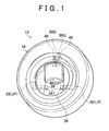
FIG. 1 is a perspective view that illustrates a filling port structure for a fuel tank according to a first embodiment of the present invention with a flap valve in a closed position as viewed from outside; -
FIGs. 2A and 2B illustrate the filling port structure for a fuel tank according to the first embodiment of the present invention with the flap valve in the closed position,FIG. 2A being a front view andFIG 2B being a sectional view that is taken along the line IIB-IIB ofFIG 2A ; -
FIG. 3 is a sectional view that is taken along the line III-III ofFIG. 2A and illustrates the filling port structure for a fuel tank according to the first embodiment of the present invention with the flap valve in a locked state; -
FIG. 4 is an enlarged perspective view that illustrates retention members and portions near the retention members in the filling port structure for a fuel tank according to the first embodiment of the present invention with lock levers in a locking position; -
FIG. 5 is a perspective view that illustrates the filling port structure for a fuel tank according to the first embodiment of the present invention with the flap valve in an open position as viewed from outside; -
FIGs. 6A and 6B illustrate the filling port structure for a fuel tank according to the first embodiment of the present invention with the flap valve during rotation from the closed position to the open position,FIG 6A being a front view andFIG. 6B being a sectional view that is taken along the line VIB-VIB ofFIG 6A ; -
FIG 7 is an enlarged perspective view that illustrates the retention members and portions near the retention members in the filling port structure for a fuel tank according to the first embodiment of the present invention with the lock levers in an unlocking position; and -
FIGs. 8A to 8D are explanatory views that illustrate the change in relative positional relationship between contacted portions and the retention members in the filling port structure for a fuel tank according to the first embodiment of the present invention. -
FIG 1 illustrates the external appearance of afilling port structure 12 for a fuel tank (which is hereinafter referred to simply as "filling port structure 12") according to a first embodiment of the present invention. As can be understood fromFIG 1 , a structure which does not require a cap that closes the filling port (so-called a capless structure) is adopted in this embodiment. - The lower end of an inlet pipe (not shown) is connected to a fuel tank (not shown). The
filling port structure 12 is provided at an upper part of the inlet pipe. The fuel tank contains gasoline in this embodiment. - A
filling port member 16 with a generally cylindrical shape is provided at an upper part of the inlet pipe. As shown also inFIG 2B and so on, a fillingport 26 is defined in the fillingport member 16, and afuel gun 28 can be inserted into the fillingport 26 through anopening 18 at the upper end thereof to refill the fuel tank. - In the following, when the term "far side" is simply used, it refers to the side in the filling
port member 16, which is close to the fuel tank (right side inFIG 2B ), and when the term "near side" is simply used, it refers to the opposite side, that is, the side from which thefuel gun 28 is inserted (left side inFIG. 2B ). The term "radial direction" refers to a radial direction of the generally cylindrical fillingport member 16. - A
flap valve 20 is provided at an upper part of the fillingport member 16, in other words, at theopening 18 of the fillingport 26. - The
flap valve 20 is rotatably attached to the fillingport member 16 by ahinge 22 provided at an upper part of theflap valve 20. Theflap valve 20 is rotatable between a closed position TP to close the filling port 26 (position indicated by solid lines) and an open position HP to open the filling port 26 (the position indicated by double-dot and dash lines). When theflap valve 20 is in the open position HP, a lower part of theflap valve 20, in other words, the side opposite the side on which thehinge 22 is located, has been largely moved to the far side (right side inFIG. 2B ). A stopper (not shown) is provided on an interior surface of the fillingport member 16 to limit the rotatable range (open position) of theflap valve 20 within a predetermined range. - The
flap valve 20 has a diameter which is larger than that of theopening 18 as a whole. As shown inFIG 3 , an annular gasket 24 (not shown inFIGs. 2A and 2B and so on) is attached to an outer periphery of theflap valve 20 so that theflap valve 20 can be held in tight contact with the peripheral edge of theopening 18. When theflap valve 20 is in the closed position TP, thegasket 24 is in close contact with the peripheral edge of the opening 18 from inside of the fillingport member 16 to close theopening 18 tightly. - A flap valve spring 36 (refer to
FIG. 2B ) is wound around thehinge 22. Theflap valve spring 36 presses theflap valve 20 toward the closed position TP so that the fillingport 26 cannot be opened accidentally. When thefuel gun 28 is inserted into theopening 18, theflap valve 20 is pressed by thefuel gun 28 and moves (rotates) to the open position HP against the pressing force of theflap valve spring 36. - As shown in
FIG. 1 andFIG 2A , paired lock levers 30 are attached to the fillingport member 16. The lock levers 30 are curved to surround theopening 18 when the fillingport member 16 is viewed from the front. The twolock levers 30 are located bilaterally symmetrically when the fillingport member 16 is viewed from the front. - A
pivot shaft 30S is provided on a longitudinal middle portion of eachlock lever 30. Thepivot shaft 30S is one example of the rotary support part in the present invention, and the lock levers 30 are rotatably supported by thepivot shafts 30S relative to the fillingport member 16 between a locking position LP that is shown inFIG. 1 andFIG. 2A and an unlocking position UP that is shown inFIG. 5 andFIG. 6A . Alock lever spring 32 is attached to the fillingport member 16. Thelock lever spring 32 presses each of the lock levers 30 toward the locking position LP. - Each
lock lever 30 has an engagingportion 30K that extends from its lower end toward the center line CL1 of the fillingport member 16 when the fillingport member 16 is viewed from the front thereof. The engagingportions 30K are located close to the center line CL1 when the lock levers 30 are in the locking position LP. The engagingportions 30K are engaged respectively with engagedparts 20K that are provided on theflap valve 20 when theflap valve 20 is in the closed position TP. This engagement rotatably locks theflap valve 20 in the closed position TP. In particular, in this embodiment, the engagingportions 30K are located apart from thehinge 22. Thus, theflap valve 20 can be tightly held in a locked state compared to the configuration in which the engagingportions 30K are located close to thehinge 22. - On the other hand, the engaging
portions 30K are located relatively farther from the center line CL1 when the lock levers 30 are in the unlocking position UP (than when the lock levers 30 are in the locking position LP). - Each
lock lever 30 has a contacted portion (contacted piece) 30Q that extends upward and toward the near side from its upper end. The contactedportions 30Q are located apart from each other when the lock levers 30 are in the locking position LP, and are located close to each other when the lock levers 30 are in the unlocking position UP. The contactedportions 30Q are respectively held in contact with retainingfaces 48H ofretention members 48 to hold the lock levers 30 in the unlocking position UP as described later. - Paired unlocking
pieces 38 are provided in theflap valve 20. The paired unlockingpieces 38 are opposed to the engagingportions 30K of the lock levers 30 in a lateral direction ofFIG. 2A . Each unlockingpiece 38 is supported by a support member (not shown) in a manner such that the unlockingpiece 38 is movable to the right and left inFIG. 2A . In particular, when the unlockingpieces 38 are moved in the direction of arrows M1 inFIG. 3 (away from each other), the unlockingpieces 38 press the engagingportions 30K of the lock levers 30 to rotate the lock levers 30 from the locking position LP to the unlocking position UP. - As shown also in
FIG. 1 , each unlockingpiece 38 has a taperedface 38T on its near side. The distance between the twotapered faces 38T is suited for a fuel gun for a fuel that should be supplied to the fuel tank (appropriate fuel). Thus, when a fuel gun for an appropriate fuel is pressed toward the inside of the fillingport 26 with its end in contact with the tapered faces 38T, the unlockingpieces 38 are moved in the direction of arrows M1 (refer toFIG. 3 ). As a result, the lock levers 30 are moved from the locking position LP to the unlocking position UP. On the contrary, a fuel gun for a fuel that should not be supplied to the fuel tank (inappropriate fuel) does not contact the tapered faces 38T (a fuel gun for an inappropriate fuel may contact one of thetapered faces 38T but does not contact both the tapered faces 38T simultaneously), and at least one of the lock levers 30 are held in the locking position LP. - As shown also in
FIG. 2B , in the fillingport member 16, aguide member 40 is provided above an insertion region SE through which thefuel gun 28 for an appropriate fuel is brought into contact with theflap valve 20.Guide pieces 42 are provided on right and left sides of theguide member 40. Each of theguide member 40 and theguide pieces 42 has a tiltedguide face 40G on its near side, which guides thefuel gun 28 into the insertion region SE when thefuel gun 28 is not inserted properly into the insertion region SE toward the fillingport 26. - In particular, the
guide member 40 is bent at an obtuse angle at a point between its oneend 40A and anotherend 40C to form abent portion 40B. The part of theguide member 40 on the oneend 40A side from thebent portion 40B has the tiltedguide face 40G, which guides thefuel gun 28 toward theflap valve 20. The part of theguide member 40 on theother end 40C side has amovement restricting face 40L that restricts the movement of thefuel gun 28 in a vertical direction (direction perpendicular to the arrow Al inFIG. 2B ) after thefuel gun 28 has been placed against theflap valve 20. - In the filling
port member 16, apivot shaft 52 that extends parallel to thehinge 22 is provided at a location above and on the near side of theguide member 40. Theguide member 40 is rotatably attached at a part near the oneend 40A (the near side end) to the fillingport member 16 using thepivot shaft 52. - A
guide member spring 54 is attached to thepivot shaft 52. Theguide member spring 54 presses theguide member 40 to urge theother end 40C upward. Theother end 40C of theguide member 40 is always held in contact with theflap valve 20 by the pressing force of theguide member spring 54. At this time, as can be understood from comparison betweenFIG 2B andFIG. 6B , the position where theother end 40C contacts theflap valve 20 moves (slides) upward (toward the hinge 22) as theflap valve 20 rotates from the closed position TP to the open position HP. - The
guide member 40 is rotated from a guiding position GP that is shown inFIG. 2B to a retracted position EP that is shown inFIG 6B by the pressing force of theguide member spring 54 as theflap valve 20 rotates from the closed position TP to the open position HP. - When the
guide member 40 is in the guiding position GP, the tiltedguide face 40G of theguide member 40 is tilted toward the center of the fillingport 26. The tilted guide face 40G guides thefuel gun 28 toward theflap valve 20, which closes the fillingport 26, when thefuel gun 28 is inserted into the fillingport 26 and the end of thefuel gun 28 contacts the tiltedguide face 40G. - On the other hand, when the
guide member 40 is in the retracted position EP, theentire guide member 40 is in a retraction region AE which is retracted from the insertion region SE for thefuel gun 28 as can be understood fromFIG. 6B . Thus, when thefuel gun 28 is inserted into the fillingport 26, thefuel gun 28 and theguide member 40 do not interfere with each other. - As shown in detail also in
FIG. 1 andFIG 5 , pairedretention members 48 are provided on the reverse face of the guide member 40 (the face on the far side when theguide member 40 is in the guiding position GP). Theretention members 48 are symmetrical with respect to the center line CL1. As shown in detail also inFIGs. 8A to 8D , a retainingface 48H, a tiltedface 48T and an introducingface 48G are formed, in this order from the bottom (the side close to the guide member 40), on each of opposing faces of theretention members 48. - When the
flap valve 20 is in the closed position TP, theguide member 40 is also in the guiding position GP. When thefuel gun 28 has not reached the tapered faces 38T of the unlockingpieces 38, the lock levers 30 are in the locking position LP as shown inFIG. 2A , and the contactedportions 30Q at the upper ends of the lock levers 30 are apart from each other. As shown also inFIG. 8A , each contactedportion 30Q is in contact with the corresponding introducingface 48G or opposed to the corresponding introducingface 48G with a small gap therebetween. In other words, the introducing faces 48G are positioned so as to have such a positional relationship with the contactedportions 30Q. - The
retention members 48 are positioned such that the retaining faces 48H are in contact with the contactedportions 30Q to hold the contactedportions 30Q close to each other in order to hold the lock levers 30 in the unlocking position when theguide member 40 is in the retracted position EP as shown inFIG. 6B (refer toFIG. 8D ). When theretention members 48 are relatively moved upward as theguide member 40 is moved from the guiding position GP toward the retracted position EP, the tilted faces 48T are brought into contact with the contactedportions 30Q and guide the contactedportions 30Q onto the retaining faces 48H (refer toFIGs. 8B to 8D ). The distance between the tilted faces 48T gradually decreases in the direction from the introducing faces 48G to the retaining faces 48H. - The
guide member 40 and theretention members 48 constitute the retention means of the present invention. - The advantageous effect of the filling
port structure 12 of this embodiment is next described below. - In a normal state, the engaging
portions 30K are engaged with the engagedparts 20K of the flap valve as shown inFIG 2A because the lock levers 30 are held in the locking position LP by the pressing force of thelock lever spring 32. Thus, theflap valve 20 is locked in the closed position TP and cannot be rotated accidentally. - At this time, the lock levers 30 are in the locking position. As shown in
FIG 4 andFIG. 8A , the contactedportions 30Q at the upper ends of the lock levers 30 are apart from each other and are in contact with the corresponding introducing faces 48G or opposed to the corresponding introducing faces 48G with a small gap therebetween. - If fuel is about to be supplied from a fuel gun for an inappropriate fuel, the fuel gun for an inappropriate fuel does not contact the tapered faces 38T of the two unlocking
pieces 38 simultaneously. The unlockingpieces 38 are not moved to the unlocking position, and the lock levers 30 are also held in the locking position LP. Because theflap valve 20 is held in the locked state, theflap valve 20 cannot be rotated from the closed position. In other words, the fuel gun for an inappropriate fuel cannot be inserted into the fillingport 26, and so-called misfueling is prevented. - In contrast, when fuel is supplied from a fuel gun for an appropriate fuel, the end of the
fuel gun 28 contacts the tapered faces 38T of the unlockingpieces 38 simultaneously, and the unlockingpieces 38 are moved away from each other (the directions of arrows M1 inFIG 3 ) by further moving thefuel gun 28 to the far side. As a result, the lock levers 30 are moved to the unlocking position UP. The contactedportions 30Q of the lock levers 30 are moved toward each other (refer toFIG. 8B ). - Because the movement of the lock levers 30 to the unlocking position UP unlocks the
flap valve 20, theflap valve 20 can be moved to the open position HP by further inserting thefuel gun 28 into the fillingport 26. Then, thefuel gun 28 can be inserted to a prescribed position in the fillingport 26 to refill the fuel tank. - As the
flap valve 20 is moved to the open position HP, theguide member 40 is moved to the retracted position EP as shown inFIG. 6B by the pressing force of theguide member spring 54. Theretention members 48 move upwards along with the movement of theguide member 40. - At this time, the contacted
portions 30Q may temporarily tend to move away from each other, but the tilted faces 48T of theretention members 48, which are moving upward, are brought into contact with the contactedportions 30Q. When the tilted faces 48T further move upward, the contactedportions 30Q are guided in a direction toward each other by the tilted faces 48T (refer toFIG. 8C ). - Then, when the
guide member 40 reaches the retracted position EP, the contactedportions 30Q of the lock levers 30 are brought into contact with the retaining faces 48H and held close to each other (refer toFIG. 8D ). As a result, the paired lock levers 30 are both held in the unlocking position UP. - When the lock levers 30 are in the unlocking position UP, the engaging
portions 30K of the lock levers 30 are located in the retraction region AE, in other words, outside the region through which thefuel gun 28 is insert into the fillingport 26. Thus, when thefuel gun 28 is inserted into the fillingport 26, thefuel gun 28 can be smoothly inserted without interference with the lock levers 30. - When the
fuel gun 28 is removed from the fillingport 26, theflap valve 20 is in the open position HP, or theflap valve 20 is somewhere between the open position HP and the closed position TP, and theguide member 40 is in the retracted position EP as can be understood fromFIG. 6B . Thus, the retaining faces 48H of theretention members 48 are in contact with the contactedportions 30Q of the lock levers 30 and the lock levers 30 are held in the unlocking position UP (refer toFIG. 6A ). Because the engagingportions 30K of the lock levers 30 do not interfere with thefuel gun 28, thefuel gun 28 can be smoothly removed from the fillingport 26. - When the
fuel gun 28 is completely removed from the fillingport 26, theflap valve 20 has returned to the closed position TP and theguide member 40 has returned to the guiding position GP as shown inFIG. 2B . The contactedportions 30Q of the lock levers 30 are opposed to (or in contact with) the introducing faces 48G of the retention members 48 (refer toFIG. 2A andFIG. 8A ). In other words, the lock levers 30 have been returned to the locking position LP by the pressing force of thelock lever spring 32 and theflap valve 20 has been locked again in the closed position TP. - As can be understood from the above description, in the filling
port structure 12 of this embodiment, because the lock levers 30 (locking members) are retracted from the insertion region SE for thefuel gun 28 and located in the retraction region AE when thefuel gun 28 is inserted into or removed from the fillingport 26, the lock levers 30 and thefuel gun 28 do not interfere with each other, allowing smooth insertion and removal of thefuel gun 28. - In particular, when a fuel gun, which includes a coil-shaped
fuel gun spring 28S wound around an outer periphery of the end thereof as shown inFIG. 6B , is used as thefuel gun 28, and thefuel gun 28 is inserted into or removed from the fillingport 26, the spring may be caught by thelock lever 30 and interfere with insertion and removal of thefuel gun 28 if the lock levers 30 are partially located in the insertion region SE for the fuel gun. The fillingport structure 12 of this embodiment allows smooth insertion and removal of thefuel gun 28 because the lock levers 30 are held in the unlocking position UP and there is a low possibility of the engagingportions 30K interfering with the spring of the fuel gun when thefuel gun 28 is inserted into or removed from the fillingport 26. - While the
guide member 40 which has a function of guiding thefuel gun 28 toward theflap valve 20 is shown in the above embodiment as a "guide member" of the present invention, the "guide member" is not limited to theguide member 40 in view of the principle of the present invention. In other words, any member that moves into the retraction region AE as theflap valve 20 is moved from the closed position TP to the open position HP does not interfere with the insertion and removal of thefuel gun 28, and the retention members can hold the lock levers 30 in the unlocking position by using the movement of the member. - While the members (lock levers 30) that are rotatably attached at their intermediate portions to the filling
port member 16 by thepivot shafts 30S are shown in the above embodiment as the locking member of the present invention, the locking member has only to be attached to the fillingport member 16 and movable between a locking position to lock theflap valve 20 in the closed position and an unlocking position to unlock theflap valve 20. For example, a slidable lock member which is slidable between a locking position and an unlocking position may be used. - While the unlocking
pieces 38 that are provided on theflap valve 20 are shown in the above embodiment as the unlocking member of the present invention, the unlocking member has only to be able to move the lock lever 30 (locking member) from the locking position LP to the unlocking position UP when pressed by thefuel gun 28 with a diameter in a specific range. For example, the unlocking member may be constituted by tapered faces that are formed at ends of the engagingportions 30K of the lock levers 30 and can rotate the lock levers 30 to the unlocking position UP when pressed by thefuel gun 28. In this case, the unlockingpieces 38 of theflap valve 20 may be omitted to reduce the number of parts. - When the unlocking member is provided separately from the locking member as in the above embodiment, the limitation on the shape of the tapered faces 38T and the displacement of the unlocking
pieces 38 can be reduced and operability in unlocking can be improved. - While an example in which the retention means of the present invention is constituted by the
guide member 40 and theretention members 48 is shown in the above embodiment, a movable member which moves as theflap valve 20 is moved from the closed position TP to the open position HP (and which does not have the function of guiding the fuel gun 28) may be provided instead of theguide member 40 and theretention members 48 may be attached to the movable member.
Claims (7)
- A filling port structure for a fuel tank, characterized by comprising:a filling port member (16) that defines a filling port into which a fuel gun for supplying fuel to a fuel tank is inserted;an open/close valve (20) that opens and closes the filling port;a rotary member (22) that attaches the open/close valve (20) to the filling port member (16) in a manner such that the open/close valve (20) is rotatable between an open position to open the filling port and a closed position to close the filling port;a locking member that is provided in the filling port member (16) and is movable between a locking position to lock the open/close valve (20) in the closed position to prevent rotation of the open/close valve (20), and an unlocking position to unlock the open/close valve (20) to allow the rotation of the open/close valve (20), wherein the locking member is located farther from a center line of the filling port member (16) when in the unlocking position than when in the locking position;an unlocking member that moves the locking member from the locking position to the unlocking position when pressed by the fuel gun with a diameter in a specific range; andretention means for holding the locking member in the unlocking position at least when the open/close valve (20) is in the open position.
- The filling port structure for a fuel tank according to claim 1, wherein: the retention means includes a guide member (40) which is located in a guiding position to guide the fuel gun toward the open/close valve (20) when the fuel gun is inserted into the filling port and moves to a retracted position in accordance with movement of the open/close valve (20) to the open position, and a retention member (48) which is provided on the guide member (40) and holds the locking member in the unlocking position by using movement of the guide member (40) to the retracted position; and
wherein the guide member (40) is located farther from the fuel gun that is inserted into the filling port when in the retracted position than when in the guiding position. - The filling port structure for a fuel tank according to claim 2, wherein: the locking member includes paired lock levers (30), and each of the paired lock levers (30) includes an engaging portion that is provided at one end of the lock lever (30) and that is engageable with the open/close valve (20) to lock the open/close valve (20), a contacted piece that is provided at another end of the lock lever (30), and a rotary support part that is provided at an intermediate portion of the lock lever (30) and that is rotatably supported on the filling port member (16); and
wherein the retention members (48) extend from the guide member (40) and are in contact with the respective contacted pieces to hold the lock levers (30) in the unlocking position when the guide member (40) is located in the retracted position. - The filling port structure for a fuel tank according to claim 3, wherein the unlocking member includes paired unlocking pieces (38), and when the paired unlocking pieces (38) are pressed by the fuel gun with the diameter within the specific range, the paired unlocking pieces (38) move away from each other and press the engaging portions of the lock levers (30) to move the lock levers (30) from the locking position to the unlocking position.
- The filling port structure for a fuel tank according to claim 3, wherein the retention members (48) include retaining faces that are contactable with the respective contacted pieces to hold the lock levers (30) in the unlocking position, and tilted faces that are continuous with the retaining faces and are tilted to guide the respective contacted pieces onto the retaining faces in accordance with movement of the guide member (40) to the retracted position.
- The filling port structure for a fuel tank according to claim 5, wherein: the retention members (48) are symmetrical with respect to the center line, and the retention members (48) further include introducing faces which are opposed to the respective contacted pieces when the lock levers (30) are in the locking position; and
wherein a distance between the tilted faces gradually decreases in a direction from the introducing faces to the retaining faces. - The filling port structure for a fuel tank according to claim 5, wherein the retention members (48) move upward and the tilted faces are brought into contact with the contacted pieces to guide the contacted pieces onto the retaining faces as the guide member (40) moves toward the retracted position.
Applications Claiming Priority (1)
| Application Number | Priority Date | Filing Date | Title |
|---|---|---|---|
| JP2011130273A JP5370420B2 (en) | 2011-06-10 | 2011-06-10 | Fuel tank fueling part structure |
Publications (2)
| Publication Number | Publication Date |
|---|---|
| EP2532551A1 true EP2532551A1 (en) | 2012-12-12 |
| EP2532551B1 EP2532551B1 (en) | 2014-03-26 |
Family
ID=46197163
Family Applications (1)
| Application Number | Title | Priority Date | Filing Date |
|---|---|---|---|
| EP12171046.1A Not-in-force EP2532551B1 (en) | 2011-06-10 | 2012-06-06 | Filing port structure for fuel tank |
Country Status (5)
| Country | Link |
|---|---|
| US (1) | US8863792B2 (en) |
| EP (1) | EP2532551B1 (en) |
| JP (1) | JP5370420B2 (en) |
| KR (1) | KR101363439B1 (en) |
| CN (1) | CN102815204B (en) |
Families Citing this family (13)
| Publication number | Priority date | Publication date | Assignee | Title |
|---|---|---|---|---|
| EP2406095B1 (en) * | 2009-03-12 | 2013-11-06 | Illinois Tool Works Inc. | Mis-fuel inhibitor |
| US10000117B2 (en) | 2012-02-17 | 2018-06-19 | Stant Usa Corp. | Filler neck closure assembly |
| EP2636555B1 (en) * | 2012-03-08 | 2014-04-30 | Magna Steyr Fuel Systems GmbH | Fill support for a diesel fuel container with a blocking device |
| JP5720850B2 (en) * | 2012-04-12 | 2015-05-20 | トヨタ自動車株式会社 | Fuel tank fueling part structure |
| KR101755751B1 (en) * | 2013-05-28 | 2017-07-07 | 현대자동차주식회사 | Fuel mixing prevention device |
| KR101481272B1 (en) * | 2013-05-28 | 2015-01-09 | 현대자동차주식회사 | Filler neck device for preventing fuel from mixing |
| JP6231843B2 (en) * | 2013-10-11 | 2017-11-15 | 株式会社アステア | Misfueling prevention device |
| US9487080B2 (en) | 2014-07-29 | 2016-11-08 | Caterpillar Inc. | Draining system for fuel tank |
| US10081241B2 (en) | 2015-12-10 | 2018-09-25 | Curtis Alan Roys | Diesel fuel guard |
| JP6520778B2 (en) * | 2016-03-17 | 2019-05-29 | 豊田合成株式会社 | Fuel port closing device |
| US9987922B2 (en) | 2016-08-16 | 2018-06-05 | Ford Global Technologies, Llc | Capless refueling mechanism |
| US10118481B1 (en) * | 2017-06-14 | 2018-11-06 | Toyota Motor Engineering & Manufacturing North America, Inc. | Fuel housing assemblies having fuel nozzle boot deflector assemblies |
| US11937673B2 (en) * | 2021-04-05 | 2024-03-26 | Aaron BRYANT | Modular wallet assembly |
Citations (6)
| Publication number | Priority date | Publication date | Assignee | Title |
|---|---|---|---|---|
| EP1690727A2 (en) * | 2005-02-10 | 2006-08-16 | Stant Manufacturing Inc. | Fuel-dispensing nozzle inhibitor |
| JP2008049952A (en) | 2006-08-28 | 2008-03-06 | Toyoda Gosei Co Ltd | Opening and closing device for tank |
| WO2008032347A1 (en) * | 2006-09-14 | 2008-03-20 | Franco Candelise | A socket for avoiding an erroneous introduction of substances in any reservoir or container |
| AT9945U1 (en) * | 2007-03-27 | 2008-06-15 | Magna Steyr Fuel Systems Gesmb | FILLING IN A FUEL TANK WITH PROTECTION BEFORE FAILING |
| DE102009009998A1 (en) * | 2009-02-23 | 2010-08-26 | Kt Projektentwicklungs Gmbh | Safety element for a diesel fuel tank to prevent misfuelling |
| US20100218849A1 (en) * | 2009-02-27 | 2010-09-02 | Toyoda Gosei Co., Ltd. | Fuel tank opening-closing device |
Family Cites Families (24)
| Publication number | Priority date | Publication date | Assignee | Title |
|---|---|---|---|---|
| US3730216A (en) * | 1972-04-06 | 1973-05-01 | Ford Motor Co | Fuel tank insert for admitting preselected pump nozzles |
| US4034784A (en) * | 1974-08-14 | 1977-07-12 | General Motors Corporation | Filler neck to inhibit use of leaded fuel |
| FR2861382B1 (en) * | 2003-10-22 | 2005-12-30 | Staubli Sa Ets | FILLING DEVICE FOR LIQUID FUEL VEHICLE TANK |
| US7077178B2 (en) * | 2004-08-11 | 2006-07-18 | Stant Manufacturing Inc. | Fuel-dispensing nozzle inhibitor |
| US7182111B2 (en) * | 2004-08-11 | 2007-02-27 | Stant Manufacturing Inc. | Fuel-dispensing nozzle inhibitor |
| US7302977B2 (en) * | 2004-09-30 | 2007-12-04 | Stant Manufacturing Inc. | Fuel-dispensing nozzle inhibitor |
| US7293586B2 (en) * | 2005-06-22 | 2007-11-13 | Stant Manufacturing Inc. | Fuel-dispensing nozzle inhibitor |
| JP4692360B2 (en) * | 2005-12-02 | 2011-06-01 | 豊田合成株式会社 | Tank opening and closing device |
| JP4892398B2 (en) * | 2007-04-23 | 2012-03-07 | 本田技研工業株式会社 | Filler pipe filler port structure |
| US7967041B2 (en) * | 2007-07-19 | 2011-06-28 | Stant Usa Corp. | Fuel-dispensing nozzle inhibitor |
| JP4379518B2 (en) * | 2007-11-29 | 2009-12-09 | トヨタ自動車株式会社 | Fuel tank fueling part structure |
| JP4403192B2 (en) * | 2007-12-25 | 2010-01-20 | 本田技研工業株式会社 | Gas cylinder holding structure of working machine equipped with gas engine |
| CA2654820C (en) * | 2008-02-21 | 2012-09-11 | Stant Manufacturing Inc. | Fuel-dispensing nozzle inhibitor |
| BRPI0908852A2 (en) * | 2008-02-22 | 2019-03-06 | Honda Motor Co Ltd | cap structure for opening the vehicle fuel filler tube |
| JP5125856B2 (en) * | 2008-07-31 | 2013-01-23 | 豊田合成株式会社 | Fuel tank opening and closing device |
| DE112009001823T5 (en) * | 2008-08-20 | 2011-06-01 | Illinois Tool Works Inc., Glenview | Mis-fuel inhibitor |
| JP5206370B2 (en) * | 2008-11-28 | 2013-06-12 | 豊田合成株式会社 | Fuel tank opening and closing device |
| JP4924644B2 (en) * | 2009-03-31 | 2012-04-25 | 豊田合成株式会社 | Fuel tank opening and closing device |
| EP2406095B1 (en) * | 2009-03-12 | 2013-11-06 | Illinois Tool Works Inc. | Mis-fuel inhibitor |
| JP5235185B2 (en) * | 2009-10-19 | 2013-07-10 | 本田技研工業株式会社 | Cassette gas cylinder loading mechanism |
| US8539993B2 (en) * | 2010-03-31 | 2013-09-24 | Toyoda Gosei Co., Ltd. | Fuel tank opening and closing device |
| JP5406158B2 (en) * | 2010-10-14 | 2014-02-05 | 豊田合成株式会社 | Fuel tank opening and closing device |
| JP5666330B2 (en) * | 2011-02-07 | 2015-02-12 | 株式会社ニフコ | Oil filler opening and closing device |
| KR101413622B1 (en) * | 2011-02-23 | 2014-07-01 | 도요타 지도샤(주) | Fuel tank fuel filler structure |
-
2011
- 2011-06-10 JP JP2011130273A patent/JP5370420B2/en not_active Expired - Fee Related
-
2012
- 2012-05-31 US US13/485,263 patent/US8863792B2/en active Active
- 2012-06-06 EP EP12171046.1A patent/EP2532551B1/en not_active Not-in-force
- 2012-06-08 KR KR1020120061423A patent/KR101363439B1/en not_active Expired - Fee Related
- 2012-06-08 CN CN201210189703.4A patent/CN102815204B/en not_active Expired - Fee Related
Patent Citations (6)
| Publication number | Priority date | Publication date | Assignee | Title |
|---|---|---|---|---|
| EP1690727A2 (en) * | 2005-02-10 | 2006-08-16 | Stant Manufacturing Inc. | Fuel-dispensing nozzle inhibitor |
| JP2008049952A (en) | 2006-08-28 | 2008-03-06 | Toyoda Gosei Co Ltd | Opening and closing device for tank |
| WO2008032347A1 (en) * | 2006-09-14 | 2008-03-20 | Franco Candelise | A socket for avoiding an erroneous introduction of substances in any reservoir or container |
| AT9945U1 (en) * | 2007-03-27 | 2008-06-15 | Magna Steyr Fuel Systems Gesmb | FILLING IN A FUEL TANK WITH PROTECTION BEFORE FAILING |
| DE102009009998A1 (en) * | 2009-02-23 | 2010-08-26 | Kt Projektentwicklungs Gmbh | Safety element for a diesel fuel tank to prevent misfuelling |
| US20100218849A1 (en) * | 2009-02-27 | 2010-09-02 | Toyoda Gosei Co., Ltd. | Fuel tank opening-closing device |
Also Published As
| Publication number | Publication date |
|---|---|
| JP2012254766A (en) | 2012-12-27 |
| JP5370420B2 (en) | 2013-12-18 |
| US20120312420A1 (en) | 2012-12-13 |
| KR101363439B1 (en) | 2014-02-14 |
| CN102815204A (en) | 2012-12-12 |
| CN102815204B (en) | 2015-04-01 |
| US8863792B2 (en) | 2014-10-21 |
| EP2532551B1 (en) | 2014-03-26 |
| KR20120137283A (en) | 2012-12-20 |
Similar Documents
| Publication | Publication Date | Title |
|---|---|---|
| EP2532551B1 (en) | Filing port structure for fuel tank | |
| US10919382B2 (en) | Rotary type extension/retraction device | |
| EP2623351B1 (en) | Arrangement structure for charging port cover | |
| US9963919B2 (en) | Locking device | |
| EP2623352B1 (en) | Arrangement structure for charging port cover | |
| EP2674317B1 (en) | Fuel-filler aperture opening/closing device | |
| US8899285B2 (en) | Fuel tank opening and closing device | |
| KR101554972B1 (en) | Fueling portion structure of fuel tank | |
| EP2130715A1 (en) | Locking device | |
| US20150048087A1 (en) | Fuel tank opening and closing device | |
| JP6682364B2 (en) | Locking device for housing unit and opening / closing body | |
| CN104937199A (en) | Lock section structure | |
| CA2898913A1 (en) | Motor vehicle door latch | |
| JP2024049256A (en) | Lid device for vehicle | |
| US9033391B2 (en) | Flap assembly for a motor vehicle | |
| KR20100095624A (en) | Capless refueling system cover with locking mechanism | |
| JP6334971B2 (en) | Open / close lock and release structure of the oil filler lid | |
| JP5741237B2 (en) | Fuel tank fueling part structure | |
| JP5347944B2 (en) | Vehicle charging port structure | |
| EP2119856B1 (en) | Lid opening operation device | |
| JP5965727B2 (en) | Lock mechanism | |
| EP2368774B1 (en) | Steering lock device | |
| JP5339189B2 (en) | Shutter mechanism and image forming apparatus | |
| JP7718369B2 (en) | Lid device for vehicle | |
| WO2012049749A1 (en) | Structure for fuel filling section of fuel tank |
Legal Events
| Date | Code | Title | Description |
|---|---|---|---|
| PUAI | Public reference made under article 153(3) epc to a published international application that has entered the european phase |
Free format text: ORIGINAL CODE: 0009012 |
|
| 17P | Request for examination filed |
Effective date: 20120606 |
|
| AK | Designated contracting states |
Kind code of ref document: A1 Designated state(s): AL AT BE BG CH CY CZ DE DK EE ES FI FR GB GR HR HU IE IS IT LI LT LU LV MC MK MT NL NO PL PT RO RS SE SI SK SM TR |
|
| AX | Request for extension of the european patent |
Extension state: BA ME |
|
| RAP1 | Party data changed (applicant data changed or rights of an application transferred) |
Owner name: TOYOTA JIDOSHA KABUSHIKI KAISHA |
|
| RIN1 | Information on inventor provided before grant (corrected) |
Inventor name: YAMAMOTO, SATOSHI Inventor name: AKAGI, MASAKI Inventor name: KATAOKA, CHIAKI |
|
| GRAP | Despatch of communication of intention to grant a patent |
Free format text: ORIGINAL CODE: EPIDOSNIGR1 |
|
| RIC1 | Information provided on ipc code assigned before grant |
Ipc: B60K 15/04 20060101AFI20130927BHEP |
|
| INTG | Intention to grant announced |
Effective date: 20131024 |
|
| RIN1 | Information on inventor provided before grant (corrected) |
Inventor name: YAMAMOTO, SATOSHI C/O TOYOTA JIDOSHA KABUSHIKI KAI Inventor name: AKAGI, MASAKI C/O TOYOTA JIDOSHA KABUSHIKI KAISHA Inventor name: KATAOKA, CHIAKI C/O TOYOTA JIDOSHA KABUSHIKI KAISH |
|
| GRAS | Grant fee paid |
Free format text: ORIGINAL CODE: EPIDOSNIGR3 |
|
| GRAA | (expected) grant |
Free format text: ORIGINAL CODE: 0009210 |
|
| RIN1 | Information on inventor provided before grant (corrected) |
Inventor name: KATAOKA, CHIAKI C/O TOYOTA JIDOSHA KABUSHIKI KAISH Inventor name: YAMAMOTO, SATOSHI C/O TOYOTA JIDOSHA KABUSHIKI KAI Inventor name: AKAGI, MASAKI C/O TOYOTA JIDOSHA KABUSHIKI KAISHA |
|
| AK | Designated contracting states |
Kind code of ref document: B1 Designated state(s): AL AT BE BG CH CY CZ DE DK EE ES FI FR GB GR HR HU IE IS IT LI LT LU LV MC MK MT NL NO PL PT RO RS SE SI SK SM TR |
|
| REG | Reference to a national code |
Ref country code: GB Ref legal event code: FG4D |
|
| REG | Reference to a national code |
Ref country code: CH Ref legal event code: EP |
|
| REG | Reference to a national code |
Ref country code: AT Ref legal event code: REF Ref document number: 658785 Country of ref document: AT Kind code of ref document: T Effective date: 20140415 |
|
| REG | Reference to a national code |
Ref country code: IE Ref legal event code: FG4D |
|
| REG | Reference to a national code |
Ref country code: DE Ref legal event code: R096 Ref document number: 602012001190 Country of ref document: DE Effective date: 20140508 |
|
| RIN2 | Information on inventor provided after grant (corrected) |
Inventor name: THE INVENTORS HAVE AGREED TO WAIVE THEIR ENTITLEME |
|
| RIN2 | Information on inventor provided after grant (corrected) |
Inventor name: THE INVENTORS HAVE AGREED TO WAIVE THEIR ENTITLEME |
|
| PG25 | Lapsed in a contracting state [announced via postgrant information from national office to epo] |
Ref country code: LT Free format text: LAPSE BECAUSE OF FAILURE TO SUBMIT A TRANSLATION OF THE DESCRIPTION OR TO PAY THE FEE WITHIN THE PRESCRIBED TIME-LIMIT Effective date: 20140326 Ref country code: NO Free format text: LAPSE BECAUSE OF FAILURE TO SUBMIT A TRANSLATION OF THE DESCRIPTION OR TO PAY THE FEE WITHIN THE PRESCRIBED TIME-LIMIT Effective date: 20140626 |
|
| REG | Reference to a national code |
Ref country code: AT Ref legal event code: MK05 Ref document number: 658785 Country of ref document: AT Kind code of ref document: T Effective date: 20140326 |
|
| REG | Reference to a national code |
Ref country code: NL Ref legal event code: VDEP Effective date: 20140326 |
|
| REG | Reference to a national code |
Ref country code: LT Ref legal event code: MG4D |
|
| PG25 | Lapsed in a contracting state [announced via postgrant information from national office to epo] |
Ref country code: SE Free format text: LAPSE BECAUSE OF FAILURE TO SUBMIT A TRANSLATION OF THE DESCRIPTION OR TO PAY THE FEE WITHIN THE PRESCRIBED TIME-LIMIT Effective date: 20140326 Ref country code: FI Free format text: LAPSE BECAUSE OF FAILURE TO SUBMIT A TRANSLATION OF THE DESCRIPTION OR TO PAY THE FEE WITHIN THE PRESCRIBED TIME-LIMIT Effective date: 20140326 |
|
| PG25 | Lapsed in a contracting state [announced via postgrant information from national office to epo] |
Ref country code: LV Free format text: LAPSE BECAUSE OF FAILURE TO SUBMIT A TRANSLATION OF THE DESCRIPTION OR TO PAY THE FEE WITHIN THE PRESCRIBED TIME-LIMIT Effective date: 20140326 Ref country code: RS Free format text: LAPSE BECAUSE OF FAILURE TO SUBMIT A TRANSLATION OF THE DESCRIPTION OR TO PAY THE FEE WITHIN THE PRESCRIBED TIME-LIMIT Effective date: 20140326 Ref country code: HR Free format text: LAPSE BECAUSE OF FAILURE TO SUBMIT A TRANSLATION OF THE DESCRIPTION OR TO PAY THE FEE WITHIN THE PRESCRIBED TIME-LIMIT Effective date: 20140326 |
|
| PG25 | Lapsed in a contracting state [announced via postgrant information from national office to epo] |
Ref country code: BG Free format text: LAPSE BECAUSE OF FAILURE TO SUBMIT A TRANSLATION OF THE DESCRIPTION OR TO PAY THE FEE WITHIN THE PRESCRIBED TIME-LIMIT Effective date: 20140626 Ref country code: BE Free format text: LAPSE BECAUSE OF FAILURE TO SUBMIT A TRANSLATION OF THE DESCRIPTION OR TO PAY THE FEE WITHIN THE PRESCRIBED TIME-LIMIT Effective date: 20140326 Ref country code: CY Free format text: LAPSE BECAUSE OF FAILURE TO SUBMIT A TRANSLATION OF THE DESCRIPTION OR TO PAY THE FEE WITHIN THE PRESCRIBED TIME-LIMIT Effective date: 20140326 Ref country code: CZ Free format text: LAPSE BECAUSE OF FAILURE TO SUBMIT A TRANSLATION OF THE DESCRIPTION OR TO PAY THE FEE WITHIN THE PRESCRIBED TIME-LIMIT Effective date: 20140326 Ref country code: RO Free format text: LAPSE BECAUSE OF FAILURE TO SUBMIT A TRANSLATION OF THE DESCRIPTION OR TO PAY THE FEE WITHIN THE PRESCRIBED TIME-LIMIT Effective date: 20140326 Ref country code: EE Free format text: LAPSE BECAUSE OF FAILURE TO SUBMIT A TRANSLATION OF THE DESCRIPTION OR TO PAY THE FEE WITHIN THE PRESCRIBED TIME-LIMIT Effective date: 20140326 Ref country code: IS Free format text: LAPSE BECAUSE OF FAILURE TO SUBMIT A TRANSLATION OF THE DESCRIPTION OR TO PAY THE FEE WITHIN THE PRESCRIBED TIME-LIMIT Effective date: 20140726 Ref country code: NL Free format text: LAPSE BECAUSE OF FAILURE TO SUBMIT A TRANSLATION OF THE DESCRIPTION OR TO PAY THE FEE WITHIN THE PRESCRIBED TIME-LIMIT Effective date: 20140326 |
|
| PG25 | Lapsed in a contracting state [announced via postgrant information from national office to epo] |
Ref country code: ES Free format text: LAPSE BECAUSE OF FAILURE TO SUBMIT A TRANSLATION OF THE DESCRIPTION OR TO PAY THE FEE WITHIN THE PRESCRIBED TIME-LIMIT Effective date: 20140326 Ref country code: AT Free format text: LAPSE BECAUSE OF FAILURE TO SUBMIT A TRANSLATION OF THE DESCRIPTION OR TO PAY THE FEE WITHIN THE PRESCRIBED TIME-LIMIT Effective date: 20140326 Ref country code: SK Free format text: LAPSE BECAUSE OF FAILURE TO SUBMIT A TRANSLATION OF THE DESCRIPTION OR TO PAY THE FEE WITHIN THE PRESCRIBED TIME-LIMIT Effective date: 20140326 Ref country code: PL Free format text: LAPSE BECAUSE OF FAILURE TO SUBMIT A TRANSLATION OF THE DESCRIPTION OR TO PAY THE FEE WITHIN THE PRESCRIBED TIME-LIMIT Effective date: 20140326 |
|
| PG25 | Lapsed in a contracting state [announced via postgrant information from national office to epo] |
Ref country code: PT Free format text: LAPSE BECAUSE OF FAILURE TO SUBMIT A TRANSLATION OF THE DESCRIPTION OR TO PAY THE FEE WITHIN THE PRESCRIBED TIME-LIMIT Effective date: 20140728 |
|
| REG | Reference to a national code |
Ref country code: DE Ref legal event code: R097 Ref document number: 602012001190 Country of ref document: DE |
|
| PG25 | Lapsed in a contracting state [announced via postgrant information from national office to epo] |
Ref country code: DK Free format text: LAPSE BECAUSE OF FAILURE TO SUBMIT A TRANSLATION OF THE DESCRIPTION OR TO PAY THE FEE WITHIN THE PRESCRIBED TIME-LIMIT Effective date: 20140326 Ref country code: MC Free format text: LAPSE BECAUSE OF FAILURE TO SUBMIT A TRANSLATION OF THE DESCRIPTION OR TO PAY THE FEE WITHIN THE PRESCRIBED TIME-LIMIT Effective date: 20140326 Ref country code: LU Free format text: LAPSE BECAUSE OF FAILURE TO SUBMIT A TRANSLATION OF THE DESCRIPTION OR TO PAY THE FEE WITHIN THE PRESCRIBED TIME-LIMIT Effective date: 20140606 |
|
| PLBE | No opposition filed within time limit |
Free format text: ORIGINAL CODE: 0009261 |
|
| STAA | Information on the status of an ep patent application or granted ep patent |
Free format text: STATUS: NO OPPOSITION FILED WITHIN TIME LIMIT |
|
| 26N | No opposition filed |
Effective date: 20150106 |
|
| REG | Reference to a national code |
Ref country code: IE Ref legal event code: MM4A |
|
| REG | Reference to a national code |
Ref country code: DE Ref legal event code: R084 Ref document number: 602012001190 Country of ref document: DE |
|
| REG | Reference to a national code |
Ref country code: FR Ref legal event code: ST Effective date: 20150227 |
|
| PG25 | Lapsed in a contracting state [announced via postgrant information from national office to epo] |
Ref country code: IT Free format text: LAPSE BECAUSE OF FAILURE TO SUBMIT A TRANSLATION OF THE DESCRIPTION OR TO PAY THE FEE WITHIN THE PRESCRIBED TIME-LIMIT Effective date: 20140326 |
|
| REG | Reference to a national code |
Ref country code: DE Ref legal event code: R097 Ref document number: 602012001190 Country of ref document: DE Effective date: 20150106 |
|
| PG25 | Lapsed in a contracting state [announced via postgrant information from national office to epo] |
Ref country code: IE Free format text: LAPSE BECAUSE OF NON-PAYMENT OF DUE FEES Effective date: 20140606 |
|
| REG | Reference to a national code |
Ref country code: DE Ref legal event code: R084 Ref document number: 602012001190 Country of ref document: DE Effective date: 20150326 |
|
| PG25 | Lapsed in a contracting state [announced via postgrant information from national office to epo] |
Ref country code: FR Free format text: LAPSE BECAUSE OF NON-PAYMENT OF DUE FEES Effective date: 20140630 |
|
| PG25 | Lapsed in a contracting state [announced via postgrant information from national office to epo] |
Ref country code: SI Free format text: LAPSE BECAUSE OF FAILURE TO SUBMIT A TRANSLATION OF THE DESCRIPTION OR TO PAY THE FEE WITHIN THE PRESCRIBED TIME-LIMIT Effective date: 20140326 |
|
| REG | Reference to a national code |
Ref country code: CH Ref legal event code: PL |
|
| PG25 | Lapsed in a contracting state [announced via postgrant information from national office to epo] |
Ref country code: MT Free format text: LAPSE BECAUSE OF FAILURE TO SUBMIT A TRANSLATION OF THE DESCRIPTION OR TO PAY THE FEE WITHIN THE PRESCRIBED TIME-LIMIT Effective date: 20140326 |
|
| PG25 | Lapsed in a contracting state [announced via postgrant information from national office to epo] |
Ref country code: SM Free format text: LAPSE BECAUSE OF FAILURE TO SUBMIT A TRANSLATION OF THE DESCRIPTION OR TO PAY THE FEE WITHIN THE PRESCRIBED TIME-LIMIT Effective date: 20140326 Ref country code: LI Free format text: LAPSE BECAUSE OF NON-PAYMENT OF DUE FEES Effective date: 20150630 Ref country code: CH Free format text: LAPSE BECAUSE OF NON-PAYMENT OF DUE FEES Effective date: 20150630 |
|
| PG25 | Lapsed in a contracting state [announced via postgrant information from national office to epo] |
Ref country code: GR Free format text: LAPSE BECAUSE OF FAILURE TO SUBMIT A TRANSLATION OF THE DESCRIPTION OR TO PAY THE FEE WITHIN THE PRESCRIBED TIME-LIMIT Effective date: 20140627 |
|
| PG25 | Lapsed in a contracting state [announced via postgrant information from national office to epo] |
Ref country code: TR Free format text: LAPSE BECAUSE OF FAILURE TO SUBMIT A TRANSLATION OF THE DESCRIPTION OR TO PAY THE FEE WITHIN THE PRESCRIBED TIME-LIMIT Effective date: 20140326 Ref country code: HU Free format text: LAPSE BECAUSE OF FAILURE TO SUBMIT A TRANSLATION OF THE DESCRIPTION OR TO PAY THE FEE WITHIN THE PRESCRIBED TIME-LIMIT; INVALID AB INITIO Effective date: 20120606 |
|
| GBPC | Gb: european patent ceased through non-payment of renewal fee |
Effective date: 20160606 |
|
| PG25 | Lapsed in a contracting state [announced via postgrant information from national office to epo] |
Ref country code: GB Free format text: LAPSE BECAUSE OF NON-PAYMENT OF DUE FEES Effective date: 20160606 |
|
| PG25 | Lapsed in a contracting state [announced via postgrant information from national office to epo] |
Ref country code: MK Free format text: LAPSE BECAUSE OF FAILURE TO SUBMIT A TRANSLATION OF THE DESCRIPTION OR TO PAY THE FEE WITHIN THE PRESCRIBED TIME-LIMIT Effective date: 20140326 |
|
| PG25 | Lapsed in a contracting state [announced via postgrant information from national office to epo] |
Ref country code: AL Free format text: LAPSE BECAUSE OF FAILURE TO SUBMIT A TRANSLATION OF THE DESCRIPTION OR TO PAY THE FEE WITHIN THE PRESCRIBED TIME-LIMIT Effective date: 20140326 |
|
| PGFP | Annual fee paid to national office [announced via postgrant information from national office to epo] |
Ref country code: DE Payment date: 20220414 Year of fee payment: 11 |
|
| P01 | Opt-out of the competence of the unified patent court (upc) registered |
Effective date: 20230427 |
|
| REG | Reference to a national code |
Ref country code: DE Ref legal event code: R119 Ref document number: 602012001190 Country of ref document: DE |
|
| PG25 | Lapsed in a contracting state [announced via postgrant information from national office to epo] |
Ref country code: DE Free format text: LAPSE BECAUSE OF NON-PAYMENT OF DUE FEES Effective date: 20240103 |