EP2531324B1 - Ring gear based welding system - Google Patents
Ring gear based welding system Download PDFInfo
- Publication number
- EP2531324B1 EP2531324B1 EP11740212.3A EP11740212A EP2531324B1 EP 2531324 B1 EP2531324 B1 EP 2531324B1 EP 11740212 A EP11740212 A EP 11740212A EP 2531324 B1 EP2531324 B1 EP 2531324B1
- Authority
- EP
- European Patent Office
- Prior art keywords
- ring gear
- welding
- pipe
- weld head
- sections
- Prior art date
- Legal status (The legal status is an assumption and is not a legal conclusion. Google has not performed a legal analysis and makes no representation as to the accuracy of the status listed.)
- Active
Links
Images




Classifications
-
- B—PERFORMING OPERATIONS; TRANSPORTING
- B23—MACHINE TOOLS; METAL-WORKING NOT OTHERWISE PROVIDED FOR
- B23K—SOLDERING OR UNSOLDERING; WELDING; CLADDING OR PLATING BY SOLDERING OR WELDING; CUTTING BY APPLYING HEAT LOCALLY, e.g. FLAME CUTTING; WORKING BY LASER BEAM
- B23K9/00—Arc welding or cutting
- B23K9/02—Seam welding; Backing means; Inserts
- B23K9/028—Seam welding; Backing means; Inserts for curved planar seams
- B23K9/0282—Seam welding; Backing means; Inserts for curved planar seams for welding tube sections
- B23K9/0286—Seam welding; Backing means; Inserts for curved planar seams for welding tube sections with an electrode moving around the fixed tube during the welding operation
-
- B—PERFORMING OPERATIONS; TRANSPORTING
- B23—MACHINE TOOLS; METAL-WORKING NOT OTHERWISE PROVIDED FOR
- B23K—SOLDERING OR UNSOLDERING; WELDING; CLADDING OR PLATING BY SOLDERING OR WELDING; CUTTING BY APPLYING HEAT LOCALLY, e.g. FLAME CUTTING; WORKING BY LASER BEAM
- B23K9/00—Arc welding or cutting
- B23K9/12—Automatic feeding or moving of electrodes or work for spot or seam welding or cutting
- B23K9/121—Devices for the automatic supply of at least two electrodes one after the other
Definitions
- the present invention relates, in general, to the welding of pipe joints and, in particular, to automated methods for welding pipe joints.
- One conventional method of welding two pipes together involves beveling the ends of the pipes such that when the pipes are arranged coaxially with respect to each other immediately before the welding process commences, an exterior circumferential groove is defined between the two pipes.
- a carriage is mounted on one of the pipes for movement around the circumference of the pipes to be joined, e.g., a conventional "bug & band" system.
- a welding torch is mounted on the carriage and the apparatus is so arranged that the end of the metal electrode of the torch is opposite and relatively close to the circumferential groove.
- the carriage is moved around the circumference of the pipe and the torch is operated so that an arc is directed into the groove.
- the arc is guided manually and/or by various mechanical sensors to guide the arc as accurately as possible along the length of the groove.
- the welding process generally takes several passes and often the passes are performed by a series of sequentially positioned welding stations on a lay-barge.
- a welding system with the features of the preamble of claim 1 is disclosed in document US-A-4 373 125 .
- FIG. 1 illustrates one embodiment of automated welding system 1.
- This embodiment generally comprises a traveling base carriage 2, a ring gear assembly 10, and one or more weld head assemblies 12 mounted on ring gear assembly 10.
- the principle components of traveling base carriage 2 consist generally of two side compartments 7A and 7B and front plate 8 fixed onto traveling platform 3.
- a floor plate 5 is positioned on a surface of a welding area or welding station. In one embodiment, this surface is the deck of a pipe laying barge or other maritime vessel. However, floor plate 5 could also be positioned at any land-based location. When floor plate 5 is positioned on a pipe laying barge, floor plate 5 will normally be located at a designated "weld station" or location on the barge where the pipe is intended to be welded.
- traveling platform 3 is able to move along floor plate 5 via rail carriage 42 riding on guide rails 43.
- guide rail 43 takes on a conventional dove-tail shape to ensure secure engagement with rail carriage 42.
- Carriage positioning mechanism 45 imparts lateral movement between the fixed floor plate 5 and traveling platform 3.
- the carriage positioning mechanism 45 consists of splined track 46 being engaged by gear 48, which is in turn powered by motor 47.
- Figure 6B shows only one motor 47, it will be understood a second one is hidden from view and corresponds with the second gear 48 seen in the Figures.
- traveling platform 3 is able to ride on the two guide rails 43 with the engagement of gear 48 and splined track 46 providing the motive force necessary for controllably positioning traveling base carriage 2, and thus ring gear assembly 10, at any lateral position along floor plate 5.
- this embodiment of ring gear assembly 10 is formed by two half ring sections 16A and 16B and ring gear mounting assemblies 75 for connecting the half ring sections 16 to front plate 8 of base carriage 3.
- each of half ring sections 16A and 16B include upper extension arm 78A and lower extension arm 78B.
- the extension arms 78A and 78B will engage horizontal guide rails 76 which are in turn fixed to mounting plates 79.
- a rail carriage 77 is bolted onto each extension arm 78 such that rail carriages 77 may slidingly engaging tracks 76, thereby allowing half ring sections 16A and 16B to move between the open and closed positions seen in Figures 3 and 2 , respectively.
- guide rails 76 and rail carriages 77 will have a mating dove tail configuration similar to guide rails 43 and rail carriages 42 described above.
- This embodiment of ring gear mounting assemblies 75 further provides a means for adjusting the vertical height of ring gear assembly 10 through the sliding connection of mounting plates 79 to front plate 8 via vertical guide rails 81.
- vertical guide rails 81 (which are oriented substantially perpendicular to guide rails 76) will be engaged by the rail carriages 77 bolted to mounting plats 79.
- a pin, catch, or other locking mechanism will engage the guide rails and rail carriages to prevent relative movement between these elements once they are in the desired position, e.g., ring gear assembly 10 is set at the desired height on vertical guide rails 81.
- Figures 2 and 3 illustrate how half ring sections 16A and 16B will move between an open and closed position. While the embodiment of Figure 2 shows the "closed position" with half ring sections 16A and 16B in actual contact, this may not be necessary for all embodiments of the invention. For example, a "closed position" with a some gap between the half ring sections is possible if the travel of weld head assemblies 12 is limited to their respective half ring sections. However, in more typical embodiments, the closed position will bring the half ring sections into mating engagement.
- the illustrated half ring sections 16 generally include mating surfaces 85 where the two half ring sections engage one another. In Figure 3 , the mating surface will include guide members formed of pin extensions 87 which engage apertures 88 (see Detail E of Figure 5 ).
- engaging engagement is not limited to any particular structure and mating engagement simply means the two half ring sections come together within sufficient tolerance to allow the weld head assemblies to transverse the connection point of the two half ring sections.
- many embodiments will include a latch or other mechanism which locks half ring sections 16A and 16B when in the closed position and is releasable to allow the half ring sections to move into the open position.
- guide rails 76 and rail carriages 77 are merely one form of mounting assembly 75 and those skilled in the art will recognize many obvious variations which are intended to come within the scope of the present invention.
- ring gear assembly 10 The general function of ring gear assembly 10 is to provide an orbital path for one or more weld head assemblies 12.
- the particular structure which the illustrated embodiments of ring gear assembly 10 employ to carry out this function is best seen in Detail E of Figure 5 .
- the open face of ring gear assembly 10 will include ring gear 22, guide track 21, and outer/inner shoulders 23A and 23B of ring gear assembly 10, all of which are circular structures set at different radial distances from the center of ring gear assembly 10.
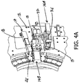
- Figures 4A and 4B illustrate how the weld head assemblies 12 will include the arcuate mounting plate 26 with a width and radius of curvature which allows mounting plate 26 to slide in an orbital path around ring gear assembly 10 between shoulders 23A and 23B.
- mounting plate 26 has a series of rollers engaging guide track 21.
- Detail C of Figure 2 shows mounting plate 26 removed but illustrates how rollers 27 would engage guide track 21.
- Detail D of Figure 2 shows a side sectional view of rollers 27 engaging guide track 21.
- Detail D also suggests how the bead track 29 formed on each side of guide track 21 and which is engaged by a center groove formed in rollers 27 will help maintain mounting plate 26 securely coupled to guide track 21.
- mounting plate 26 forms the attachment point for the other components of weld head assembly 12 to ring gear assembly 10.
- a weld head assembly positioner 17, which in the illustrated embodiment is positioning motor 18, will engage mounting plate 26.
- Positioning motor 18 will have a shaft which extends through mounting plate 26 and drives a gear 19 (see detail C in Figure 2 ) which engages ring gear 22.
- the splines of gear 19 will engage the cogs on ring gear 22 such that torque applied by positioning motor 18 to gear 19 will cause mounting plate 26 (and thus weld head assembly 12) to move in an orbital path along guide track 21.
- positioning motor 18 is a model no. BM200 available from Aerotech, Inc. of Pittsburgh, PA.
- ring gear assembly 10 gear and guide track structure
- ring gear 22 could alternatively be on the inner perimeter of guide track 21.
- a single ring gear 22 could be provided with two guide tracks 21 (e.g., a guide track on both the inner and outer perimeter of the ring gear).
- welding torch 13 other components of weld head assembly 12 directly or indirectly positioned on mounting plate 26 include a welding torch 13, a two torch positioners 14A and 14B, and a torch position sensor 15.
- welding torch 13 illustrated in Figure 4A is a dual torch configuration, the use of "welding torch” in the singular will refer to any of a single torch, dual torch, or other torch configuration.
- the torch positioners 14A and 14B (as best seen in Figure 4B ) include a mounting rail 36 (also sometimes referred to as a "linear stage") and a sliding bracket 37 which moves along mounting rail 36.
- torch positioners 14A and 14B are PRO-115 series linear actuators manufactured by Aerotech, Inc. of Pittsburgh, PA.
- mounting rail 36 of torch positioner 14B is bolted to mounting plate 26.
- a worm gear within mounting rail 36 engages sliding bracket 37 and is rotated by motor 38, causing sliding bracket 37 to moved along the length of mounting rail 36.
- a side mounting bracket 34 is attached to sliding bracket 37. Attached to side mounting bracket 34 is the torch positioner 14A.
- torch positioner 14A also has a mounting rail 36 and a sliding bracket 37 to which torch 13 is attached.
- the mounting rail 36 for torch position 14A is somewhat shorter than that for torch position 14B since torch positioner 14A can function with a lesser range of movement.
- the torch With torch 13 attached to sliding bracket 37 of positioner 14A, the torch can move in the "x" direction (i.e., parallel to a pipe section being welded) defined by the co-ordinate reference seen in Figures 4B and 5 .
- positioner 14A itself is attached to the sliding bracket 37 of the positioner 14B, thereby allowing positioner 14A (and thus torch 13) to move back and forth in the "y" direction shown in Figures 4B and 5 (i.e., moving torch 13 radially toward and away from the pipe section).
- torch positioner 14B is fixed to mounting plate 26, it can be seen that the orbital path of mounting plate 26 (the "z" direction shown in Figure 4B ) will move torch 13 around the circumference of a pipe positioned through center opening 11 of ring gear assembly 10.
- a position sensor 15 is positioned adjacent to torch 13 on torch positioner 14A.
- position sensor 15 is mounted directly on torch positioner 14A and therefore moves with the torch 13.
- position sensor 15 could be mounted independently of either torch positioner (e.g., on any open area of mounting plate 26) and not move in either the "y" or "x" directions.
- position sensor 15 is a combination laser/CCD device which can identify surface features on the pipe (e.g., the joint between two pipes which are being welded). Such laser/CCD devices are described in US Patent No. 6,430,472 which is incorporated by reference herein in its entirety.
- Position sensor 15 provides data on the position of torch 13 relative to the pipe joint being welded and allows a controller (described below) to move the torch 13, via positioners 14A and 14B, in the necessary pattern to properly weld the pipe joint.
- the embodiment showing in Figure 1 mounts the AUTO-TRAC® control components 68 on side compartment 7.
- the position sensor could be any suitable conventional or future developed position sensing technique, including thru-the-arc sensing which detects a change in arc voltage based on torch distance from the pipe joint, or mechanical sensing which uses a physical wand or probe in contact with the pipe joint.
- Example welding technologies include gas metal arc welding (GMAW), gas tungsten arc welding (GTAW), flux cord arc welding (FCAW), or laser beam welding (LBW), but other conventional and future developed welding methods should be considered within the scope of the present invention.
- GMAW gas metal arc welding
- GTAW gas tungsten arc welding
- FCAW flux cord arc welding
- LBW laser beam welding
- the number of weld head assemblies positioned on ring gear assembly 10 may vary based upon factors such as the welding technology employed and the size of the pipe being welded.
- GMAW one embodiment employs two weld head assemblies 12, while other embodiment could employ just one weld head assembly 12 or possibly 3, 4, or more weld head assemblies 12.
- LBW or plasma arc welding systems preferred embodiments may employ a single weld head assembly (but could also employ multiple weld head assemblies).
- FIG 1 illustrates weld-head flexible supply conduits (or hoses) 40 extending between the torches 13 and wire feed assemblies 30 which are positioned on the walls of side compartments 7.
- the torch is the type using a consumable wire in the welding process (e.g., gas metal arc welding)
- wire is fed through hoses 40 to torches 13 by feed assemblies 30 as is known in the art.
- a supply of wire is typically stored on a spool or reel (not shown) and is usually drawn off the reel by a feed motor in order to feed torches 13 in a controlled manner.
- Hose 40 may also enclose power cables for the torch and positioner motors along with electrical control lines to the positioner motors and position sensors on weld head assemblies 12.
- hoses 40 are flexible and of sufficient length to accommodate a weld head assembly 12's intended orbital path around ring gear assembly 10. For example, if two weld head assemblies 12 are employed, the hoses 40 may only need to be long enough to accommodate a half-orbit path, whereas if one weld head assembly 12 is employed, the hoses may need to be long enough to accommodate a full orbit of travel by the weld head assembly.
- FIGS 7 and 8 illustrate an alternate embodiment of the inventive welding system.
- welding system 100 includes a unitary ring gear assembly 110, i.e., a ring gear assembly which is a continuous ring of material (or at least multiple segments fixed together in a semi-permanent manner) as opposed to the readily separable segments as in the previous embodiment.
- a pair of vertically adjustable ring gear assembly brackets 106 will mount ring gear assembly 110 on ring gear assembly stand 104. Ring gear assembly brackets 106 will allow the height of ring gear assembly 110's center aperture 111 to be adjusted to approximately match the height of the pipe sections being welded, as is explained in more detail below.
- weld head assemblies 112 are substantially the same as weld head assemblies 12 described above. However weld head assemblies 112 are of a single torch configuration. As suggested in Figure 7 , welding system 100 will have a travel base carriage 102 mounted on a traveling platform 103 which moves on floor plate 105 in a manner similar to that described above in reference to traveling base carriage 2.
- Figure 8 illustrates weld-head flexible supply conduits (or hoses) 140 extending between the torches 113 and wire feed assemblies 130 which are positioned on a sidewalls of ring gear assembly stand 104.
- hoses 140 are flexible and of sufficient length to accommodate a weld head assembly 112's intended orbital path around ring gear assembly 110.
- certain embodiments of the welding system will include the floor plate 105 positioned on the deck 50 of a pipe-laying barge.
- this pipe-laying barge example is described in relation to welding system 100, it will be understood that the description is equally applicable to welding system 1.
- the pipe-laying barge will have a series of support rollers 70 which support the individual pipe sections (before welding) and then the continuous pipeline portion (after welding).
- support rollers 70 are shown in Figure 9 , it will be understood that other support rollers to the right and left of those shown allow the pipe sections to lie level with the ends abutting at joint 56.
- an internal clamp (not shown) will bridge the pipe joint within the two pipe sections and hold the ends of the pipe sections securely together.
- the welding system is barge based, it can be envisioned that as individual pipe sections 55 (entering the welding area or weld station from the left) are welded together, a continuous pipe line of welded sections is formed and exits the weld station to the right.
- other equipment on the barge deck such as pipe tensioners (not seen in the figures) are typically holding the pipe sections in tension while letting the weight of the overboard pipeline and the barge's forward movement slowly move the pipe sections in a continuous process through one or more weld stations along the deck of the pipe laying barge. In this manner, the completed pipeline is continuously exiting the barge and being positioned on the sea-bed even as the length of the pipeline is being extended by the welding of new pipe sections to the pipeline.
- the ring gear assembly 110 (and thus base carriage 2) is not connected to the pipe sections and may move independently of pipe sections.
- This may be distinguished from prior art "bug & band" systems where a band connects circumferentially around the pipe adjacent to the pipe joint and the weld head assembly is attached to and travels along the band.
- bug & band systems where a band connects circumferentially around the pipe adjacent to the pipe joint and the weld head assembly is attached to and travels along the band.
- One significant disadvantage with conventional bug and band systems occurs when tensioner failure releases a pipe section allowing the pipe section to move through the weld stations at a high and uncontrolled speed. In this very dangerous situation, the bug & band structure along with the attached weld head assembly is carried with the pipe causing significant damage or injury to any equipment or personnel in the path of the bug and band structure.
- welding systems 1 or 100 when employing the above described welding systems 1 or 100, a rapid and uncontrolled movement of the pipe sections does not drag extraneous equipment along with the pipe and is
- FIG. 10 shows schematically one embodiment of system controller 60.
- system controller 60 is divided into two control racks, primary control rack 61A and secondary control rack 61B, which control (among other functions) the weld head assemblies 12A and 12B, respectively.
- Each of the control racks 61 will further comprise a series of conventional PC based controllers 62-65, each of which will typically comprise a control card for driving one or more servo motors, input/output cards, and a microprocessor.
- One example of such a controller is the Ensemble CP provided by Aerotech, Inc. of Pittsburgh, PA.
- controllers 62 control the respective positioning motors 18 and the thus the orbital or "z" position (see Figure 4B ) of the weld head assemblies.
- Controllers 63 control the respective positioners 14A and thus the longitudinal or "y” direction movement the welding torches 13.
- Controllers 64 control the respective positioners 14B and thus the radial or "x” direction movement the welding torches 13.
- Controllers 65 control the carriage motors 47 ( Figure 6B ) and thus the position of traveling base carriage 2.
- Each of the controllers 62 act as the master controller for their respective control racks.
- controller 62A acts as the master for controller 62B via communications link 66.
- the control racks 61 may be mounted within side compartments 7.
- system controller 60 is just one example of a suitable control system and in alternate embodiments, the system controller 60 could be devices such as programmable logic controllers or possibly even hard-wired circuitry.
- a user interface 40 ( Figure 1 ) will allow users to input information and instructions to system controller 60.
- the user interface is a conventional human machine interface (HMI) 41 providing touch screen input features.
- HMI human machine interface
- One suitable HMI is a Silver Series 5121-X provided by Maple Systems, Inc. of Everett, WA.
- user interface 40 could be another interface system such as a conventional keyboard, monitor, and mouse device.
- FIG. 11 Viewing Figure 11 in conjunction with Figure 9 illustrates one example of a welding cycle which could be implemented by system controller 60.
- the operator initiates starting movement of the traveling base carriage 102 toward the direction of the approaching pipe joint 56.
- the laser/camera components of position sensor 15 will determine when pipe joint 56 passes under the camera.
- base carriage 102 changes velocity (speed and direction) as necessary to begin tracking pipe joint 56.
- the loop between steps 203 and 204 will allow base carriage 102 position itself such that the welding torches 13 on weld head assemblies 12 are centered over (or approximately centered over) pipe joint 56.
- Steps 205 to 207 allow the operator to visually confirm the centering of torches 13 over pipe joint 56 and make any necessary manual adjustments if an acceptable alignment is not visually confirmed.
- the operator manually initiates the weld cycle.
- Steps 209 to 212 will perform a welding loop where the position of the welding torch 13 is continuously corrected (if required) as the torches proceed in their orbital path while welding the circumference of pipe joint 56.
- the control software continuously adjusts the torch position based upon an x-y positioning feed back from the AUTO-TRAC® controller in order to maintain the welding torch at a predetermined height above the welding surface.
- the weld head assemblies 12 may also be controlled by a memory mapping mode which records the x-y coordinates from the preceding weld path and repeats this path based on the coordinates.
- the weld head assemblies will return to a pre-designated start position.
- base carriage 102 will move back to a pre-designated start position. It will be understood that base carriage 102 is maintaining a velocity (both speed and direction) approximate to that of pipe joint 56 during the embodiment the welding steps of this process.
- Alternative control systems could use other feedback parameters to control the weld path.
- one alternative control system could make comparisons of welding feedback parameters (e.g., arc voltage and current, torch oscillation speed and width, and travel speed of arc) with a database of such parameters which has been empirically determined to provide optimal welds.
- welding feedback parameters e.g., arc voltage and current, torch oscillation speed and width, and travel speed of arc
- another alternative control system would be a manual controller an operator may use to adjust the x-y position of the welding torach.
- Figure 11 represent just one possible control sequence and any number of variations are within the scope of the invention.
- the system could be completely automated with no inputs from a human operator.
- the base carriage 102's pre-designated start position could be close to the boarder where the pipe joint 56 will enter the welding station.
- the base carriage could begin tracking pipe joint 56 and initiate the other steps described above.
- FIG. 9 illustrates a joint sensor 164 positioned on the front of traveling platform 103.
- joint sensor 164 would be a laser/camera distance finder 165.
- a roller sensor 66 such as an encoder which counts the turns of roller 70A and would use this information on roller turns to calculate details regarding the pipe velocity and distanced travel in a given time period.
- the weld head assembly will make a full orbit around pipe joint 56 to weld the entire circumference of the joint.
- the most time efficient embodiment of the single weld head assembly system will make a full orbit weld in one continuous 360° trip of weld head assembly 12 (i.e., the weld head assembly does not back-track over a previous welded arc of the pipe joint).
- a full orbit weld may be accomplished by a single weld head assembly 12 welding the circumference of the pipe in broken segments.
- weld head assembly 12 could weld (clockwise) from the 12 o'clock position to the 6 o'clock position, cease welding and move back to the 12 o'clock position, and then begin welding again (counter-clockwise) toward the 6 o'clock position.
- a single weld head assembly 12 is considered to make a full orbit weld as long substantially the entire circumference of the joint is welded, regardless of how continuous or discontinuous the weld path is.
- the first weld head assembly 12A may begin welding clock-wise from the 12 o'clock position while the weld head assembly 12B stands by at the 9 o'clock position. As weld head assembly 12A reaches the 3 o'clock position, weld head assembly 12B would move to the 12 o'clock position and begin welding in the counter-clockwise position.
- weld head assembly 12A When weld head assembly 12A finishes its weld path at the 6 o'clock position, it will retreat to its starting position before weld head assembly 12B terminates it weld path at the 6 o'clock position.
- the sensor 15 on the weld head assemblies scan the weld.
- the scanning of the weld allows the computer system to determine the height of the weld bead in the groove of the pipe joint.
- the computer system can record the profile of the weld bead as detected by the camera and compare the actual weld bead profile to a database of joint geometry tolerance profiles. If the weld bead is determined to be noncompliant, the system can generate an alert signal for the operator or take other corrective action.
- Another aspect of the present invention is a method of centering a pipe section within the welding system described herein. More precisely, this involves repositioning the ring gear assembly such that its center point corresponds to the center point of the pipe section.
- centering the pipe section within the ring gear assembly is not critical for all embodiments, it is often advantageous to center the pipe section so that the weld joint will be equal distant from weld head assemblies along the entire circumference of the ring gear assembly.
- this method will begin with positioning the pipe section within the ring gear assembly (i.e., with the pipe section supported by rollers on each side of the ring gear assembly as suggested in Figure 9 ). Next, at least one reading of the distance from the outer surface of the pipe section to the position sensor is obtained. Finally, the ring gear assembly is repositioned in order to move the center point of the ring gear assembly closer to the center point of pipe section.
- the position sensor used in determining the distance to the pipe section's outer surface is simply the position sensor 15 ( Figure 4B ) mounted on the weld head assemblies as described above.
- the method may still be practiced with greater margins of error between the pipe section center point and the ring gear assembly center point (e.g., an error of less than 5 cm, or less than 4 cm, or less than 3 cm, or less than 2 cm).
- the system controller will use this information to move the ring gear assembly up/down or left/right (i.e., from the perspective seen in Figure 2 ).
- the ring gear assembly 10 may be moved left or right by mounting assemblies 75 traveling on horizontal guide rails 76 and up/down by traveling on vertical guide rails 81.
- motor and gear assemblies would be adapted to move the rail carriages 77 ( Figure 1 ) in a controlled manner along guide rails 76 and 81.
- These motor/gear assemblies would likewise be controlled by the system controller, thereby allowing the up/down, left/right position of ring gear assembly (and thus the center point of the ring gear assembly) to be precisely controlled.
- the required direction and magnitude of ring gear assembly movement may be calculated in order to match the ring gear center point with the pipe section center point. For example, if the pipe section diameter has been input into the welding system, then possibly a single reading of the distance between the position sensor and the outer surface of the pipe section will provide sufficient information to approximately align the two center points. However, more typically, at least two distance measurements along the circumference of the pipe joint allow a more accurate alignment of the center points. As an alternative to employing a known pipe diameter in the positioning calculation, the position sensor could take several distance measurements around the circumference of the ring gear.
- the controller would compute the magnitude and direction of mounting assemblies 75's movement such that the out surface of the pipe section would be equal distant from the inner diameter of the ring gear at all circumferential points of measurement (thus aligning the center points of the pipe section and ring gear assembly).
- the controller would compute the magnitude and direction of mounting assemblies 75's movement such that the out surface of the pipe section would be equal distant from the inner diameter of the ring gear at all circumferential points of measurement (thus aligning the center points of the pipe section and ring gear assembly).
- Figure 12 illustrates a still further embodiment of the present invention, ring gear assembly 310.
- This ring gear assembly includes an open throat 350 formed by a gap in the ring gear body where the gap has an arc length represented by theta in Figure 12 .
- theta is between about 60° and about 120° degrees and in one preferred embodiment, is about 80° degrees.
- throat 350 will be somewhat wider than the largest diameter pipe expected to be welded by ring gear assembly 310, preferably with approximately one half inch clearance on each side of throat 350.
- Ring gear assembly 310 has one or more weld head assemblies 312 which will include a welding torch, a torch positioner, and a position sensor such as described in the previous embodiments.
- mounting plate 326 differs somewhat from previous embodiments in that mounting plate 326 has a greater arcuate length and in the illustrated embodiment, will have sufficient length to position the welding torch across at least half of open throat 350 when weld head assembly 312 is in its lower most (i.e., closest to throat 350) position. It can be visualized that this allows the weld head assemblies 312 to extend into the open area of throat 350 and weld the underside of pipe section 360.
- positioning motors 318 must be located at a distance sufficiently far from weld head assemblies 312 such that the weld head assemblies may extend into throat 350 while positioning motors 318 remain engaged with guide track 321 and ring gear 322.
- the embodiment of Figure 12 shows two ring gear assemblies 310 where the mounting plates 326 have sufficient length to allow the weld head assemblies 312 to extend about half way across the throat gap.
- ring gear assembly 310 Another feature of ring gear assembly 310 is the saddle brace 330 which forms a bracing and guide mechanism for the pipe section 360 onto which ring gear assembly 310 is positioned.
- Figure 12 also shows two securing clamps 331 which, together with saddle brace 330, secure pipe section 360 within ring gear assembly 310.
- securing clamps 331 are hydraulic (or pneumatic) ram and cylinder assemblies (only the rams are visible in Figure 12 with the cylinder assemblies hidden behind the body of the ring gear assembly).
- the securing clamps are not limited ram and cylinder assemblies and could be any other linear actuator device (e.g., power screws) or some type of non-linear (e.g., pivoting) clamping mechanism.
- saddle brace 330 has a face section for engaging pipe section 330 which is generally curved to correspond to the expected pipe curvature and has an arc length of between about 20° and about 60° and more preferably about 40° for engaging a pipe section.
- the ring gear assembly 310 may be mounted on a traveling base carriage such as seen in Figures 1 and 7 .
- ring gear assembly 310 includes a hanging bracket positioned generally opposite the open throat 350, thereby allowing ring gear assembly 310 to suspend by some type of overhead assembly (e.g., crane, overhead gantry system, etc.).
- hanging bracket 340 is a lifting eye having an ear section with an aperture formed through the ear sections.
- hanging bracket 340 could be any conventional or future developed structure allowing ring gear assembly to be suspended from a structure above the ring gear assembly.
- One alternate embodiment includes a method of welding a pipe joint comprising the steps of: (a) positioning at least two sections of pipe extending through a weld system ring gear assembly mounted on a base carriage, the sections of pipe being mounted independently of the base carriage; (b) positioning the base carriage to detect a pipe joint along a line of the pipe sections; (c) setting a velocity of the base carriage to approximately the velocity of the pipe joint's lateral movement in order to maintain the position of the weld-head approximately at the pipe joint; (d) scanning the pipe joint with a position sensor mounted on the ring gear assembly; (e) welding of the pipe joint with a welding torch mounted on the ring gear assembly; and (f) re-scanning a weld for defects with the position sensor as the weld head assembly returns to a start position.
- Another embodiment is a welding system comprising: (a) a traveling base carriage; (b) carriage positioning mechanism engaging the base carriage; (c) a ring gear assembly mounted on the base carriage; and (d) a weld head assembly mounted on the ring gear assembly.
- the weld head assembly includes (i) a welding torch; (ii) a torch positioner; and (iii) a position sensor.
- a line of pipe sections extend through the ring gear and are positioned independent of the traveling carriage.
- a joint sensor is spaced apart from the weld-heads and a system controller is programmed to control the carriage and the weld-head to perform the steps of: (i) detecting a pipe joint along a line of pipe sections; (ii) setting a velocity of the base carriage to approximate the pipe joint's lateral movement in order to maintain the position of the weld head assembly approximately at the pipe joint; (iii) simultaneously scanning of the pipe joint with the position sensor and welding of the pipe joint with the welding torch; and (iv) adjusting a path of the welding torch to accommodate a geometry of the pipe joint as detected by the position sensor.
- This embodiment could further perform the step of re-scanning a completed weld for defects with the position sensor as the weld-head returns to a start position.
- the weld head assembly may comprise a first torch positioner moving the welding torch in a radial direction and a second torch positioner moving the welding torch in a lateral direction. Additionally, a third positioner may engage a gear on the ring gear assembly and move the weld head assembly in an angular direction.
- the positioning sensor may comprise a camera having a filter for filtering light wavelengths produced by welding with the welding torch.
- the base carriage moves independently of the pipe sections.
- a still further embodiment is a welding system comprising a ring gear assembly having an open throat and at least one weld-head assembly mounted on the ring gear assembly.
- the weld-head assembly including a mounting plate comprising: i) a welding torch, ii) a torch positioner, and iii) a position sensor.
- the mounting plate has sufficient length to position the welding torch across at least about one half of the open throat.
- a system controller is programmed to control the weld-head assembly to adjust a path of the welding torch to accommodate a geometry of the pipe joint as detected by the position sensor.
- the open throat comprises an arcuate gap of between about 60 and about 120 degrees.
- the ring gear assembly further comprises a saddle brace and at least one movable positioning arm opposing the saddle brace.
- there are at least two movable positioning arms wherein the movable positioning arms comprise piston and cylinder assemblies.
- the saddle brace may have an arcuate surface between about 20 and about 60 degrees for engaging a pipe section.
- This ring gear assembly may also have a hanging bracket positioned generally opposite the open throat.
Landscapes
- Engineering & Computer Science (AREA)
- Physics & Mathematics (AREA)
- Plasma & Fusion (AREA)
- Mechanical Engineering (AREA)
- Butt Welding And Welding Of Specific Article (AREA)
Description
- The present invention relates, in general, to the welding of pipe joints and, in particular, to automated methods for welding pipe joints.
- When laying a pipeline at sea it is customary to weld, on a lay-barge, individual pipe sections into a pipe string (with the pipe string leading towards the seabed). The pipe-string is under great tension while being laid and weld joints must be sufficiently strong to withstand the high forces imposed on the weld joints. Each time a pipe is welded to another pipe, extensive tests are made to ensure that the quality of the weld joint formed is sufficient. The strength of a weld joint depends upon various factors, one being the geometry of the path traced by the point of contact of the arc in relation to the surfaces of the pipes to be joined. If the point of contact of the arc is not closely controlled, the quality of the weld may be insufficient.
- One conventional method of welding two pipes together involves beveling the ends of the pipes such that when the pipes are arranged coaxially with respect to each other immediately before the welding process commences, an exterior circumferential groove is defined between the two pipes. A carriage is mounted on one of the pipes for movement around the circumference of the pipes to be joined, e.g., a conventional "bug & band" system. A welding torch is mounted on the carriage and the apparatus is so arranged that the end of the metal electrode of the torch is opposite and relatively close to the circumferential groove. The carriage is moved around the circumference of the pipe and the torch is operated so that an arc is directed into the groove. The arc is guided manually and/or by various mechanical sensors to guide the arc as accurately as possible along the length of the groove. The welding process generally takes several passes and often the passes are performed by a series of sequentially positioned welding stations on a lay-barge.
- In pipe laying, the welding process is highly repetitive requiring the welding of hundreds of pipe joints per day with multiple passes on each pipe joint. Therefore, even small increases in the speed of the individual welding cycle for each pipe joint can result in significant operational
- A welding system with the features of the preamble of
claim 1 is disclosed in documentUS-A-4 373 125 . -
-
Figure 1 is an isometric view of one embodiment of the automated welding system of the present invention. -
Figure 2 is a front view of the welding system seen inFigure 1 . -
Figure 3 illustrates a ring gear assembly in the separated position. -
Figures 4A and4B are enlarged views of one embodiment of the weld head assembly.Figure 5 illustrates a sectional view of the ring gear assembly. -
Figure 6 illustrates one embodiment of the carriage positioning mechanism. -
Figure 7 is an isometric view of an alternative embodiment of the present invention.Figure 8 is a rear view of the embodiment ofFigure 7 . -
Figure 9 illustrates theFigure 7 embodiment welding the joint of two pipe sections. -
Figure 10 is a component diagram of one control mechanism for the illustrated embodiments. -
Figure 11 is flow chart illustrating an example operational sequence of certain embodiments of the present invention. -
Figure 12 illustrates a third embodiment of the ring gear assembly of the present invention. -
Figure 1 illustrates one embodiment ofautomated welding system 1. This embodiment generally comprises atraveling base carriage 2, aring gear assembly 10, and one or moreweld head assemblies 12 mounted onring gear assembly 10. InFigure 1 , the principle components oftraveling base carriage 2 consist generally of twoside compartments 7A and 7B and front plate 8 fixed ontotraveling platform 3. Typically, afloor plate 5 is positioned on a surface of a welding area or welding station. In one embodiment, this surface is the deck of a pipe laying barge or other maritime vessel. However,floor plate 5 could also be positioned at any land-based location. Whenfloor plate 5 is positioned on a pipe laying barge,floor plate 5 will normally be located at a designated "weld station" or location on the barge where the pipe is intended to be welded. Often there will be multiple weld stations on a barge and awelding system 1 could be positioned at each weld station. As seen inFigures 1 and2 , travelingplatform 3 is able to move alongfloor plate 5 via rail carriage 42 riding onguide rails 43. As suggested by the end view ofFigure 2 , the cross-section of this example ofguide rail 43 takes on a conventional dove-tail shape to ensure secure engagement with rail carriage 42. - Many embodiments of the welding system will include a carriage positioning mechanism, one example of which is seen in
Figure 6B . Carriage positioning mechanism 45 imparts lateral movement between thefixed floor plate 5 andtraveling platform 3. In the embodiment shown in Detail F ofFigure 6B , the carriage positioning mechanism 45 consists ofsplined track 46 being engaged bygear 48, which is in turn powered bymotor 47. AlthoughFigure 6B shows only onemotor 47, it will be understood a second one is hidden from view and corresponds with thesecond gear 48 seen in the Figures. ViewingFigure 2 , it will be apparent how travelingplatform 3 is able to ride on the twoguide rails 43 with the engagement ofgear 48 andsplined track 46 providing the motive force necessary for controllably positioningtraveling base carriage 2, and thusring gear assembly 10, at any lateral position alongfloor plate 5. - As seen in
Figures 2 and3 , this embodiment ofring gear assembly 10 is formed by twohalf ring sections gear mounting assemblies 75 for connecting the half ring sections 16 to front plate 8 ofbase carriage 3. As part of this embodiment ofmounting assemblies 75, each ofhalf ring sections upper extension arm 78A andlower extension arm 78B. Theextension arms horizontal guide rails 76 which are in turn fixed to mountingplates 79. As suggested in detail A ofFigure 1 , arail carriage 77 is bolted onto eachextension arm 78 such thatrail carriages 77 may slidingly engagingtracks 76, thereby allowinghalf ring sections Figures 3 and2 , respectively. In this embodiment,guide rails 76 andrail carriages 77 will have a mating dove tail configuration similar toguide rails 43 and rail carriages 42 described above. This embodiment of ringgear mounting assemblies 75 further provides a means for adjusting the vertical height ofring gear assembly 10 through the sliding connection ofmounting plates 79 to front plate 8 viavertical guide rails 81. As suggested in detail B ofFigure 1 , vertical guide rails 81 (which are oriented substantially perpendicular to guide rails 76) will be engaged by therail carriages 77 bolted to mountingplats 79. In many embodiments, a pin, catch, or other locking mechanism will engage the guide rails and rail carriages to prevent relative movement between these elements once they are in the desired position, e.g.,ring gear assembly 10 is set at the desired height onvertical guide rails 81. -
Figures 2 and3 illustrate howhalf ring sections Figure 2 shows the "closed position" withhalf ring sections mating surfaces 85 where the two half ring sections engage one another. InFigure 3 , the mating surface will include guide members formed ofpin extensions 87 which engage apertures 88 (see Detail E ofFigure 5 ). However, those skilled in the art will recognize many other techniques for guiding thehalf ring sections 12 into a well aligned engagement. "Mating engagement" is not limited to any particular structure and mating engagement simply means the two half ring sections come together within sufficient tolerance to allow the weld head assemblies to transverse the connection point of the two half ring sections. Although not specifically illustrated, many embodiments will include a latch or other mechanism which lockshalf ring sections - Although the embodiment seen in the figures contemplates manual positioning of the
half ring sections guide rails 76, other embodiments could automate this positioning function using worm gears, piston and cylinder assemblies, or other conventional or future developed positioning mechanisms. Likewise,guide rails 76 andrail carriages 77 are merely one form of mountingassembly 75 and those skilled in the art will recognize many obvious variations which are intended to come within the scope of the present invention. - The general function of
ring gear assembly 10 is to provide an orbital path for one or moreweld head assemblies 12. The particular structure which the illustrated embodiments ofring gear assembly 10 employ to carry out this function is best seen in Detail E ofFigure 5 . The open face ofring gear assembly 10 will includering gear 22,guide track 21, and outer/inner shoulders ring gear assembly 10, all of which are circular structures set at different radial distances from the center ofring gear assembly 10.Figures 4A and4B illustrate how theweld head assemblies 12 will include the arcuate mountingplate 26 with a width and radius of curvature which allows mountingplate 26 to slide in an orbital path aroundring gear assembly 10 betweenshoulders plate 26 has a series of rollers engagingguide track 21. Detail C ofFigure 2 shows mounting plate 26 removed but illustrates howrollers 27 would engageguide track 21. Detail D ofFigure 2 shows a side sectional view ofrollers 27 engagingguide track 21. Detail D also suggests how the bead track 29 formed on each side ofguide track 21 and which is engaged by a center groove formed inrollers 27 will help maintain mountingplate 26 securely coupled to guidetrack 21. - It will also be apparent from the figures that mounting
plate 26 forms the attachment point for the other components ofweld head assembly 12 to ringgear assembly 10. A weldhead assembly positioner 17, which in the illustrated embodiment is positioningmotor 18, will engage mountingplate 26. Positioningmotor 18 will have a shaft which extends through mountingplate 26 and drives a gear 19 (see detail C inFigure 2 ) which engagesring gear 22. The splines of gear 19 will engage the cogs onring gear 22 such that torque applied by positioningmotor 18 to gear 19 will cause mounting plate 26 (and thus weld head assembly 12) to move in an orbital path alongguide track 21. In one embodiment, positioningmotor 18 is a model no. BM200 available from Aerotech, Inc. of Pittsburgh, PA. - Although detail E in
Figure 5 illustrates one embodiment ofring gear assembly 10's gear and guide track structure, those skilled in the art will see that many modifications are possible. For example, rather than being on the outer perimeter ofguide track 21,ring gear 22 could alternatively be on the inner perimeter ofguide track 21. Alternatively, there could be tworings 22, e.g., a ring gear on each side ofguide track 21. As a still further alternative, asingle ring gear 22 could be provided with two guide tracks 21 (e.g., a guide track on both the inner and outer perimeter of the ring gear). These and other modifications to ringgear assembly 10 should be considered within the scope of the present invention. - Returning to
Figure 4A , other components ofweld head assembly 12 directly or indirectly positioned on mountingplate 26 include awelding torch 13, a twotorch positioners torch position sensor 15. Although theparticular welding torch 13 illustrated inFigure 4A is a dual torch configuration, the use of "welding torch" in the singular will refer to any of a single torch, dual torch, or other torch configuration. - The
torch positioners Figure 4B ) include a mounting rail 36 (also sometimes referred to as a "linear stage") and a slidingbracket 37 which moves along mountingrail 36. In one embodiment,torch positioners rail 36 oftorch positioner 14B is bolted to mountingplate 26. Although hidden from view in the figures, a worm gear within mountingrail 36 engages slidingbracket 37 and is rotated bymotor 38, causing slidingbracket 37 to moved along the length of mountingrail 36. It can be seen inFigure 4B that aside mounting bracket 34 is attached to slidingbracket 37. Attached to side mountingbracket 34 is thetorch positioner 14A. ViewingFigure 4A ,torch positioner 14A also has a mountingrail 36 and a slidingbracket 37 to whichtorch 13 is attached. However, it can be seen that the mountingrail 36 fortorch position 14A is somewhat shorter than that fortorch position 14B sincetorch positioner 14A can function with a lesser range of movement. - With
torch 13 attached to slidingbracket 37 ofpositioner 14A, the torch can move in the "x" direction (i.e., parallel to a pipe section being welded) defined by the co-ordinate reference seen inFigures 4B and5 . Likewise,positioner 14A itself is attached to the slidingbracket 37 of thepositioner 14B, thereby allowingpositioner 14A (and thus torch 13) to move back and forth in the "y" direction shown inFigures 4B and5 (i.e., movingtorch 13 radially toward and away from the pipe section). Becausetorch positioner 14B is fixed to mountingplate 26, it can be seen that the orbital path of mounting plate 26 (the "z" direction shown inFigure 4B ) will movetorch 13 around the circumference of a pipe positioned through center opening 11 ofring gear assembly 10. - As also shown in
Figure 4A , aposition sensor 15 is positioned adjacent to torch 13 ontorch positioner 14A. In this embodiment,position sensor 15 is mounted directly ontorch positioner 14A and therefore moves with thetorch 13. However, in other embodiments,position sensor 15 could be mounted independently of either torch positioner (e.g., on any open area of mounting plate 26) and not move in either the "y" or "x" directions. In the embodiment shown,position sensor 15 is a combination laser/CCD device which can identify surface features on the pipe (e.g., the joint between two pipes which are being welded). Such laser/CCD devices are described inUS Patent No. 6,430,472 which is incorporated by reference herein in its entirety. A commercial embodiment of such a sensor is the AUTO-TRAC® laser vision system provided by Servo-Robot, Inc. of St-Bruno, Canada.Position sensor 15 provides data on the position oftorch 13 relative to the pipe joint being welded and allows a controller (described below) to move thetorch 13, viapositioners Figure 1 mounts the AUTO-TRAC® control components 68 onside compartment 7. In alternative embodiments, the position sensor could be any suitable conventional or future developed position sensing technique, including thru-the-arc sensing which detects a change in arc voltage based on torch distance from the pipe joint, or mechanical sensing which uses a physical wand or probe in contact with the pipe joint. - Different types of
torches 13 may be used with the present positioning system. Example welding technologies include gas metal arc welding (GMAW), gas tungsten arc welding (GTAW), flux cord arc welding (FCAW), or laser beam welding (LBW), but other conventional and future developed welding methods should be considered within the scope of the present invention. The number of weld head assemblies positioned onring gear assembly 10 may vary based upon factors such as the welding technology employed and the size of the pipe being welded. For GMAW, one embodiment employs twoweld head assemblies 12, while other embodiment could employ just oneweld head assembly 12 or possibly 3, 4, or moreweld head assemblies 12. When using LBW or plasma arc welding systems, preferred embodiments may employ a single weld head assembly (but could also employ multiple weld head assemblies). -
Figure 1 illustrates weld-head flexible supply conduits (or hoses) 40 extending between thetorches 13 andwire feed assemblies 30 which are positioned on the walls of side compartments 7. Where the torch is the type using a consumable wire in the welding process (e.g., gas metal arc welding), wire is fed throughhoses 40 totorches 13 byfeed assemblies 30 as is known in the art. A supply of wire is typically stored on a spool or reel (not shown) and is usually drawn off the reel by a feed motor in order to feedtorches 13 in a controlled manner.Hose 40 may also enclose power cables for the torch and positioner motors along with electrical control lines to the positioner motors and position sensors onweld head assemblies 12. Although not shown, the control lines will run to a controller, which in certain embodiments is a computer system positioned withinside compartment 7. In this embodiment,hoses 40 are flexible and of sufficient length to accommodate aweld head assembly 12's intended orbital path aroundring gear assembly 10. For example, if twoweld head assemblies 12 are employed, thehoses 40 may only need to be long enough to accommodate a half-orbit path, whereas if oneweld head assembly 12 is employed, the hoses may need to be long enough to accommodate a full orbit of travel by the weld head assembly. -
Figures 7 and8 illustrate an alternate embodiment of the inventive welding system. In this embodiment,welding system 100 includes a unitaryring gear assembly 110, i.e., a ring gear assembly which is a continuous ring of material (or at least multiple segments fixed together in a semi-permanent manner) as opposed to the readily separable segments as in the previous embodiment. ViewingFigure 8 , a pair of vertically adjustable ring gear assembly brackets 106 will mountring gear assembly 110 on ringgear assembly stand 104. Ring gear assembly brackets 106 will allow the height ofring gear assembly 110's center aperture 111 to be adjusted to approximately match the height of the pipe sections being welded, as is explained in more detail below. Theweld head assemblies 112 are substantially the same asweld head assemblies 12 described above. Howeverweld head assemblies 112 are of a single torch configuration. As suggested inFigure 7 ,welding system 100 will have atravel base carriage 102 mounted on a travelingplatform 103 which moves onfloor plate 105 in a manner similar to that described above in reference to travelingbase carriage 2. - Similar to the embodiment described in
Figure 1 ,Figure 8 illustrates weld-head flexible supply conduits (or hoses) 140 extending between thetorches 113 and wire feed assemblies 130 which are positioned on a sidewalls of ringgear assembly stand 104. As with the earlier embodiment,hoses 140 are flexible and of sufficient length to accommodate aweld head assembly 112's intended orbital path aroundring gear assembly 110. - As suggested in
Figure 9 , certain embodiments of the welding system will include thefloor plate 105 positioned on thedeck 50 of a pipe-laying barge. Although this pipe-laying barge example is described in relation towelding system 100, it will be understood that the description is equally applicable towelding system 1. Typically the pipe-laying barge will have a series of support rollers 70 which support the individual pipe sections (before welding) and then the continuous pipeline portion (after welding). Although only two support rollers 70 are shown inFigure 9 , it will be understood that other support rollers to the right and left of those shown allow the pipe sections to lie level with the ends abutting at joint 56. In many situations, an internal clamp (not shown) will bridge the pipe joint within the two pipe sections and hold the ends of the pipe sections securely together. If the welding system is barge based, it can be envisioned that as individual pipe sections 55 (entering the welding area or weld station from the left) are welded together, a continuous pipe line of welded sections is formed and exits the weld station to the right. It will be understood that other equipment on the barge deck such as pipe tensioners (not seen in the figures) are typically holding the pipe sections in tension while letting the weight of the overboard pipeline and the barge's forward movement slowly move the pipe sections in a continuous process through one or more weld stations along the deck of the pipe laying barge. In this manner, the completed pipeline is continuously exiting the barge and being positioned on the sea-bed even as the length of the pipeline is being extended by the welding of new pipe sections to the pipeline. It will be apparent from the embodiment ofFigure 9 that the ring gear assembly 110 (and thus base carriage 2) is not connected to the pipe sections and may move independently of pipe sections. This may be distinguished from prior art "bug & band" systems where a band connects circumferentially around the pipe adjacent to the pipe joint and the weld head assembly is attached to and travels along the band. One significant disadvantage with conventional bug and band systems occurs when tensioner failure releases a pipe section allowing the pipe section to move through the weld stations at a high and uncontrolled speed. In this very dangerous situation, the bug & band structure along with the attached weld head assembly is carried with the pipe causing significant damage or injury to any equipment or personnel in the path of the bug and band structure. On the other hand, when employing the above describedwelding systems - The illustrated embodiments of the
welding systems Figure 10 shows schematically one embodiment of system controller 60. In this example, system controller 60 is divided into two control racks,primary control rack 61A and secondary control rack 61B, which control (among other functions) theweld head assemblies 12A and 12B, respectively. Each of the control racks 61 will further comprise a series of conventional PC based controllers 62-65, each of which will typically comprise a control card for driving one or more servo motors, input/output cards, and a microprocessor. One example of such a controller is the Ensemble CP provided by Aerotech, Inc. of Pittsburgh, PA. InFigure 10 , controllers 62 (i.e., 62A and 62B) control therespective positioning motors 18 and the thus the orbital or "z" position (seeFigure 4B ) of the weld head assemblies. Controllers 63 control therespective positioners 14A and thus the longitudinal or "y" direction movement the welding torches 13. Controllers 64 control therespective positioners 14B and thus the radial or "x" direction movement the welding torches 13. Controllers 65 control the carriage motors 47 (Figure 6B ) and thus the position of travelingbase carriage 2. Each of the controllers 62 act as the master controller for their respective control racks. For certain limited functions such as determining the relative orbital positions of the two weld head assemblies,controller 62A acts as the master for controller 62B via communications link 66. As seen in the embodiment ofFigure 1 , the control racks 61 may be mounted within side compartments 7. - However, system controller 60 is just one example of a suitable control system and in alternate embodiments, the system controller 60 could be devices such as programmable logic controllers or possibly even hard-wired circuitry. In addition to the components discussed above, a user interface 40 (
Figure 1 ) will allow users to input information and instructions to system controller 60. In the embodiment ofFigure 1 , the user interface is a conventional human machine interface (HMI) 41 providing touch screen input features. One suitable HMI is a Silver Series 5121-X provided by Maple Systems, Inc. of Everett, WA. Alternatively,user interface 40 could be another interface system such as a conventional keyboard, monitor, and mouse device. - Viewing
Figure 11 in conjunction withFigure 9 illustrates one example of a welding cycle which could be implemented by system controller 60. Instep 201, the operator initiates starting movement of the travelingbase carriage 102 toward the direction of the approaching pipe joint 56. Instep 202, the laser/camera components ofposition sensor 15 will determine when pipe joint 56 passes under the camera. Instep 203,base carriage 102 changes velocity (speed and direction) as necessary to begin tracking pipe joint 56. The loop betweensteps base carriage 102 position itself such that the welding torches 13 onweld head assemblies 12 are centered over (or approximately centered over)pipe joint 56. Steps 205 to 207 allow the operator to visually confirm the centering oftorches 13 over pipe joint 56 and make any necessary manual adjustments if an acceptable alignment is not visually confirmed. Instep 208, the operator manually initiates the weld cycle.Steps 209 to 212 will perform a welding loop where the position of thewelding torch 13 is continuously corrected (if required) as the torches proceed in their orbital path while welding the circumference of pipe joint 56. In the illustrated embodiment, the control software continuously adjusts the torch position based upon an x-y positioning feed back from the AUTO-TRAC® controller in order to maintain the welding torch at a predetermined height above the welding surface. In a preferred embodiment, theweld head assemblies 12 may also be controlled by a memory mapping mode which records the x-y coordinates from the preceding weld path and repeats this path based on the coordinates. Once the weld torch has reached its stop position (e.g., completion of its 180° circuit in a system having two weld head assemblies 12), the weld head assemblies will return to a pre-designated start position. Instep 214,base carriage 102 will move back to a pre-designated start position. It will be understood thatbase carriage 102 is maintaining a velocity (both speed and direction) approximate to that of pipe joint 56 during the embodiment the welding steps of this process. Alternative control systems could use other feedback parameters to control the weld path. For example one alternative control system could make comparisons of welding feedback parameters (e.g., arc voltage and current, torch oscillation speed and width, and travel speed of arc) with a database of such parameters which has been empirically determined to provide optimal welds. In addition to the memory mapping mode described above, another alternative control system would be a manual controller an operator may use to adjust the x-y position of the welding torach. - Of course,
Figure 11 represent just one possible control sequence and any number of variations are within the scope of the invention. For example, the system could be completely automated with no inputs from a human operator. In one embodiment of such a completely automated system, thebase carriage 102's pre-designated start position could be close to the boarder where the pipe joint 56 will enter the welding station. When the pipe joint 56 is detected passing underposition sensor 15, the base carriage could begin tracking pipe joint 56 and initiate the other steps described above. - A still further alternative system could employ a separate joint sensor position within the weld station.
Figure 9 illustrates a joint sensor 164 positioned on the front of travelingplatform 103. One example of joint sensor 164 would be a laser/camera distance finder 165. In another alterative, aroller sensor 66 such as an encoder which counts the turns ofroller 70A and would use this information on roller turns to calculate details regarding the pipe velocity and distanced travel in a given time period. - In the embodiment where there is only one
weld head assembly 12, the weld head assembly will make a full orbit around pipe joint 56 to weld the entire circumference of the joint. The most time efficient embodiment of the single weld head assembly system will make a full orbit weld in one continuous 360° trip of weld head assembly 12 (i.e., the weld head assembly does not back-track over a previous welded arc of the pipe joint). However, a full orbit weld may be accomplished by a singleweld head assembly 12 welding the circumference of the pipe in broken segments. For example, theweld head assembly 12 could weld (clockwise) from the 12 o'clock position to the 6 o'clock position, cease welding and move back to the 12 o'clock position, and then begin welding again (counter-clockwise) toward the 6 o'clock position. Thus, a singleweld head assembly 12 is considered to make a full orbit weld as long substantially the entire circumference of the joint is welded, regardless of how continuous or discontinuous the weld path is. - As suggested by the above description, there will be many embodiments providing two or more
weld head assemblies 12 positioned on thering gear assembly 10. In such embodiments, it may be advantageous to stagger the start times and positions of the various weld head assemblies so that they do not interfere with one another. Using the two weld head assemblies seen inFigure 2 as an example, the firstweld head assembly 12A may begin welding clock-wise from the 12 o'clock position while the weld head assembly 12B stands by at the 9 o'clock position. Asweld head assembly 12A reaches the 3 o'clock position, weld head assembly 12B would move to the 12 o'clock position and begin welding in the counter-clockwise position. Whenweld head assembly 12A finishes its weld path at the 6 o'clock position, it will retreat to its starting position before weld head assembly 12B terminates it weld path at the 6 o'clock position. In certain embodiments, as theweld head assemblies 12 returns to their start or "home" positions, thesensor 15 on the weld head assemblies scan the weld. The scanning of the weld allows the computer system to determine the height of the weld bead in the groove of the pipe joint. The computer system can record the profile of the weld bead as detected by the camera and compare the actual weld bead profile to a database of joint geometry tolerance profiles. If the weld bead is determined to be noncompliant, the system can generate an alert signal for the operator or take other corrective action. - Another aspect of the present invention is a method of centering a pipe section within the welding system described herein. More precisely, this involves repositioning the ring gear assembly such that its center point corresponds to the center point of the pipe section. Although centering the pipe section within the ring gear assembly is not critical for all embodiments, it is often advantageous to center the pipe section so that the weld joint will be equal distant from weld head assemblies along the entire circumference of the ring gear assembly. Typically, this method will begin with positioning the pipe section within the ring gear assembly (i.e., with the pipe section supported by rollers on each side of the ring gear assembly as suggested in
Figure 9 ). Next, at least one reading of the distance from the outer surface of the pipe section to the position sensor is obtained. Finally, the ring gear assembly is repositioned in order to move the center point of the ring gear assembly closer to the center point of pipe section. - In many embodiments, the position sensor used in determining the distance to the pipe section's outer surface is simply the position sensor 15 (
Figure 4B ) mounted on the weld head assemblies as described above. However, in alternate embodiments, a separate position sensor separate from the weld head assemblies to could be used to measure the distance to the pipe for centering purposes. It is not necessary to move the center point of the pipe section to the exact center point of the ring gear, but it is preferred to have the pipe section center point within 1 cm of the ring gear assembly's center point. However, the method may still be practiced with greater margins of error between the pipe section center point and the ring gear assembly center point (e.g., an error of less than 5 cm, or less than 4 cm, or less than 3 cm, or less than 2 cm). - Normally, once the position sensor has determined the distance to outer surface of the pipe section, the system controller will use this information to move the ring gear assembly up/down or left/right (i.e., from the perspective seen in
Figure 2 ). Using the embodiment ofFigure 2 as an example, thering gear assembly 10 may be moved left or right by mountingassemblies 75 traveling onhorizontal guide rails 76 and up/down by traveling on vertical guide rails 81. While not explicitly showing in the drawings, motor and gear assemblies would be adapted to move the rail carriages 77 (Figure 1 ) in a controlled manner alongguide rails - There are numerous ways in which the required direction and magnitude of ring gear assembly movement may be calculated in order to match the ring gear center point with the pipe section center point. For example, if the pipe section diameter has been input into the welding system, then possibly a single reading of the distance between the position sensor and the outer surface of the pipe section will provide sufficient information to approximately align the two center points. However, more typically, at least two distance measurements along the circumference of the pipe joint allow a more accurate alignment of the center points. As an alternative to employing a known pipe diameter in the positioning calculation, the position sensor could take several distance measurements around the circumference of the ring gear. Thereafter, the controller would compute the magnitude and direction of mounting
assemblies 75's movement such that the out surface of the pipe section would be equal distant from the inner diameter of the ring gear at all circumferential points of measurement (thus aligning the center points of the pipe section and ring gear assembly). Those skilled in the art will recognize that there are many alternative methods to compute the magnitude and direction of the ring gear assembly movement in order to obtain center point alignment and all such methods should be considered within the scope of the present invention. -
Figure 12 illustrates a still further embodiment of the present invention,ring gear assembly 310. This ring gear assembly includes anopen throat 350 formed by a gap in the ring gear body where the gap has an arc length represented by theta inFigure 12 . In certain embodiments, theta is between about 60° and about 120° degrees and in one preferred embodiment, is about 80° degrees. Typicallythroat 350 will be somewhat wider than the largest diameter pipe expected to be welded byring gear assembly 310, preferably with approximately one half inch clearance on each side ofthroat 350. -
Ring gear assembly 310 has one or moreweld head assemblies 312 which will include a welding torch, a torch positioner, and a position sensor such as described in the previous embodiments. However, mountingplate 326 differs somewhat from previous embodiments in that mountingplate 326 has a greater arcuate length and in the illustrated embodiment, will have sufficient length to position the welding torch across at least half ofopen throat 350 whenweld head assembly 312 is in its lower most (i.e., closest to throat 350) position. It can be visualized that this allows theweld head assemblies 312 to extend into the open area ofthroat 350 and weld the underside ofpipe section 360. Naturally,positioning motors 318 must be located at a distance sufficiently far fromweld head assemblies 312 such that the weld head assemblies may extend intothroat 350 while positioningmotors 318 remain engaged withguide track 321 andring gear 322. The embodiment ofFigure 12 shows tworing gear assemblies 310 where the mountingplates 326 have sufficient length to allow theweld head assemblies 312 to extend about half way across the throat gap. - Another feature of
ring gear assembly 310 is thesaddle brace 330 which forms a bracing and guide mechanism for thepipe section 360 onto whichring gear assembly 310 is positioned.Figure 12 also shows two securingclamps 331 which, together withsaddle brace 330,secure pipe section 360 withinring gear assembly 310. In the embodiment shown, securingclamps 331 are hydraulic (or pneumatic) ram and cylinder assemblies (only the rams are visible inFigure 12 with the cylinder assemblies hidden behind the body of the ring gear assembly). However, the securing clamps are not limited ram and cylinder assemblies and could be any other linear actuator device (e.g., power screws) or some type of non-linear (e.g., pivoting) clamping mechanism. In the example ofFigure 12 ,saddle brace 330 has a face section for engagingpipe section 330 which is generally curved to correspond to the expected pipe curvature and has an arc length of between about 20° and about 60° and more preferably about 40° for engaging a pipe section. - In certain embodiments, the
ring gear assembly 310 may be mounted on a traveling base carriage such as seen inFigures 1 and7 . However, in the embodiment ofFigure 12 ,ring gear assembly 310 includes a hanging bracket positioned generally opposite theopen throat 350, thereby allowingring gear assembly 310 to suspend by some type of overhead assembly (e.g., crane, overhead gantry system, etc.). In one example, hangingbracket 340 is a lifting eye having an ear section with an aperture formed through the ear sections. However, hangingbracket 340 could be any conventional or future developed structure allowing ring gear assembly to be suspended from a structure above the ring gear assembly. - One alternate embodiment includes a method of welding a pipe joint comprising the steps of: (a) positioning at least two sections of pipe extending through a weld system ring gear assembly mounted on a base carriage, the sections of pipe being mounted independently of the base carriage; (b) positioning the base carriage to detect a pipe joint along a line of the pipe sections; (c) setting a velocity of the base carriage to approximately the velocity of the pipe joint's lateral movement in order to maintain the position of the weld-head approximately at the pipe joint; (d) scanning the pipe joint with a position sensor mounted on the ring gear assembly; (e) welding of the pipe joint with a welding torch mounted on the ring gear assembly; and (f) re-scanning a weld for defects with the position sensor as the weld head assembly returns to a start position.
- Another embodiment is a welding system comprising: (a) a traveling base carriage; (b) carriage positioning mechanism engaging the base carriage; (c) a ring gear assembly mounted on the base carriage; and (d) a weld head assembly mounted on the ring gear assembly. The weld head assembly includes (i) a welding torch; (ii) a torch positioner; and (iii) a position sensor. A line of pipe sections extend through the ring gear and are positioned independent of the traveling carriage. A joint sensor is spaced apart from the weld-heads and a system controller is programmed to control the carriage and the weld-head to perform the steps of: (i) detecting a pipe joint along a line of pipe sections; (ii) setting a velocity of the base carriage to approximate the pipe joint's lateral movement in order to maintain the position of the weld head assembly approximately at the pipe joint; (iii) simultaneously scanning of the pipe joint with the position sensor and welding of the pipe joint with the welding torch; and (iv) adjusting a path of the welding torch to accommodate a geometry of the pipe joint as detected by the position sensor. This embodiment could further perform the step of re-scanning a completed weld for defects with the position sensor as the weld-head returns to a start position.
- In the above embodiment, the weld head assembly may comprise a first torch positioner moving the welding torch in a radial direction and a second torch positioner moving the welding torch in a lateral direction. Additionally, a third positioner may engage a gear on the ring gear assembly and move the weld head assembly in an angular direction. The positioning sensor may comprise a camera having a filter for filtering light wavelengths produced by welding with the welding torch. In a modification of this embodiment, the base carriage moves independently of the pipe sections.
- A still further embodiment is a welding system comprising a ring gear assembly having an open throat and at least one weld-head assembly mounted on the ring gear assembly. The weld-head assembly including a mounting plate comprising: i) a welding torch, ii) a torch positioner, and iii) a position sensor. The mounting plate has sufficient length to position the welding torch across at least about one half of the open throat. A system controller is programmed to control the weld-head assembly to adjust a path of the welding torch to accommodate a geometry of the pipe joint as detected by the position sensor. In this embodiment, the open throat comprises an arcuate gap of between about 60 and about 120 degrees. Alternatively, the ring gear assembly further comprises a saddle brace and at least one movable positioning arm opposing the saddle brace. In one embodiment, there are at least two movable positioning arms wherein the movable positioning arms comprise piston and cylinder assemblies. Additionally, the saddle brace may have an arcuate surface between about 20 and about 60 degrees for engaging a pipe section. This ring gear assembly may also have a hanging bracket positioned generally opposite the open throat.
- Although the present invention has been described in terms of specific embodiments, those skilled in the art will see many obvious variations and modifications. For example, the illustrated embodiments show the welding system mounted on generally horizontal surfaces (e.g., the deck of a pipe laying barge). However, a variation of the traveling base carriage could also be mounted "sideways" on a vertical surface. All such variations and modifications are intended to come within the scope of the following claims.
Claims (12)
- A welding system (1) comprising:a. a traveling base carriage (2):b. a carriage positioning mechanism (45) engaging the base carriage (2);c. a ring gear assembly (10) mounted on the base carriage (2);d. at least one weld head assembly (12) mounted on the ring gear assembly (10), the weld head assembly (12) including: i) a welding torch (13); ii) a torch positioner (14A, 14B), and iii) a position sensor (15);e. a line of pipe sections extending through the ring gear assembly (10) and not being connected to the ring gear assembly (10) such that the pipe sections may move independently of the ring gear assembly (10);characterised by:f. a system controller programmed to control at least the carriage positioning mechanism (45) and the weld head assembly (12) to perform the following steps:i. detecting a pipe joint along the line of pipe sections;ii. setting a velocity of the base carriage (2) to approximate the pipe joint's lateral movement in order to maintain the position of the weld head assembly (12) approximately at the pipe joint;iii. simultaneously scanning the pipe joint with the position sensor (15) and welding the pipe joint with the welding torch (13); andiv. adjusting a path of the welding torch (13) to accommodate a geometry of the pipe joint as detected by the position sensor (15).
- The welding system (1) according to claim 1, wherein the ring gear assembly (10) comprises:i. two half ring sections (16A, 16B), each including at least one gear track;ii. a ring gear mount attaching each of the half ring sections (16A, 16B) to the base carriage (2), the ring gear mounts allowing the half ring sections (16A, 16B) to separate and guiding the half ring sections (16A, 16B) into mating engagement.
- The welding system (1) according to claim 2, wherein the ring gear mounts comprise tracks positioned on the base carriage (2) and guide rails positioned on the half ring sections.
- The welding system (1) according to claim 3, wherein the half ring sections (16A, 16B) each include upper and lower extension arms to which the guide rails are attached.
- The welding system (1) according to claim 3, wherein the ring gear mounts comprising a first track positioned between said base carriage (2) and a mounting plate, and a second track positioned on the mounting plate and being substantially perpendicular to the first track.
- The welding system (1) according to claim 5, wherein the second track is positioned horizontally such that extension arms of the half ring sections (16A, 16B) may travel along the second track.
- The welding system (1) according to claim 2, wherein the half ring sections (16A, 16B) have mating surfaces and guide members in order to align the gear tracks on the half ring sections (16A, 16B).
- The welding system (1) according to claim 1, the controller further performing the step of moving the base carriage (2) along a pipe section until a pipe joint is detected and then tracking the pipe joint with the weld head assembly (12) positioned approximately at the pipe joint.
- The welding system (1) according to claim 1, further comprising two weld head assemblies having electric arc welding torches.
- The welding system (1) according to claim 1, wherein the weld head assembly (12) comprises a laser welding torch (13).
- The welding system (1) according to claim 10, wherein the weld head assembly (12) has a single laser welding torch (13).
- The welding system (1) according to claim 11, wherein the weld head assembly (12) traverses a substantially full orbit around the ring gear assembly (10).
Applications Claiming Priority (2)
| Application Number | Priority Date | Filing Date | Title |
|---|---|---|---|
| US12/698,815 US8916791B2 (en) | 2010-02-02 | 2010-02-02 | Ring gear based welding system |
| PCT/US2011/022968 WO2011097131A1 (en) | 2010-02-02 | 2011-01-28 | Ring gear based welding system |
Publications (3)
| Publication Number | Publication Date |
|---|---|
| EP2531324A1 EP2531324A1 (en) | 2012-12-12 |
| EP2531324A4 EP2531324A4 (en) | 2017-07-12 |
| EP2531324B1 true EP2531324B1 (en) | 2018-08-01 |
Family
ID=44340745
Family Applications (1)
| Application Number | Title | Priority Date | Filing Date |
|---|---|---|---|
| EP11740212.3A Active EP2531324B1 (en) | 2010-02-02 | 2011-01-28 | Ring gear based welding system |
Country Status (8)
| Country | Link |
|---|---|
| US (1) | US8916791B2 (en) |
| EP (1) | EP2531324B1 (en) |
| AU (1) | AU2011213158B8 (en) |
| BR (1) | BR112012019300A2 (en) |
| CA (1) | CA2788564C (en) |
| MX (1) | MX2012008990A (en) |
| MY (1) | MY157240A (en) |
| WO (1) | WO2011097131A1 (en) |
Families Citing this family (31)
| Publication number | Priority date | Publication date | Assignee | Title |
|---|---|---|---|---|
| US8502866B2 (en) * | 2008-03-14 | 2013-08-06 | Illinois Tool Works Inc. | Video recording device for a welder's helmet |
| US8099184B2 (en) * | 2009-04-13 | 2012-01-17 | Rimrock Automation, Inc. | Load compensation for robotic applications |
| US9475155B2 (en) | 2010-02-02 | 2016-10-25 | Technip Usa, Inc. | Ring gear based welding system |
| US20130008881A1 (en) * | 2011-07-06 | 2013-01-10 | Paul John Berbakov | Orbital Welding Apparatus |
| US9573215B2 (en) * | 2012-02-10 | 2017-02-21 | Illinois Tool Works Inc. | Sound-based weld travel speed sensing system and method |
| JP5843683B2 (en) * | 2012-03-28 | 2016-01-13 | 株式会社神戸製鋼所 | Tandem welding torch |
| LV14659B (en) * | 2012-08-07 | 2013-06-20 | Toms Torims | Apparatus and method for repair and renovation of crankshaft journal surfaces in-situ by means of laser build-up |
| ITTO20130248A1 (en) * | 2013-03-26 | 2014-09-27 | Illinois Tool Works | ORBITAL WELDING DEVICE WITH QUICK POSITION |
| US11090753B2 (en) | 2013-06-21 | 2021-08-17 | Illinois Tool Works Inc. | System and method for determining weld travel speed |
| US20150129581A1 (en) * | 2013-11-12 | 2015-05-14 | Lincoln Global, Inc. | System and method for pendant component for a welding system |
| CN104625362A (en) * | 2013-11-15 | 2015-05-20 | 中国石油天然气集团公司 | Pipeline welding double-machine-head rotating device and technological method |
| US10166621B2 (en) * | 2014-03-14 | 2019-01-01 | Kawasaki Jukogyo Kabushiki Kaisha | Welding device and welding system |
| US9922460B2 (en) | 2014-11-04 | 2018-03-20 | Illinois Tool Works Inc. | Stereoscopic helmet display |
| US10032388B2 (en) | 2014-12-05 | 2018-07-24 | Illinois Tool Works Inc. | Augmented and mediated reality welding helmet systems |
| CN107020476A (en) * | 2017-05-21 | 2017-08-08 | 无锡市翱宇特新科技发展有限公司 | A kind of big rack welding device |
| CN108453447B (en) * | 2018-05-07 | 2020-06-09 | 嘉应学院 | A pipe fitting welding robot |
| CN108857203B (en) * | 2018-08-20 | 2023-05-23 | 安徽科技学院 | A surrounding welding device for heat-insulating pipe heads |
| GB2591544B (en) * | 2019-10-09 | 2023-07-26 | Dril Quip Inc | Subsea well intervention cap and method of deployment of subsea well intervention cap |
| CN110802310B (en) * | 2019-10-25 | 2024-04-30 | 安徽麦克威链传动制造有限公司 | Automatic welding machine for chain wheels |
| CN111702379B (en) * | 2020-05-11 | 2021-10-01 | 芜湖懒人智能科技有限公司 | An internal and external welding device for a trash can shell integrating internal welding and external welding functions |
| CN112122731A (en) * | 2020-08-27 | 2020-12-25 | 耒阳市亚湘电子科技有限公司 | Novel soldering gun that accuracy is high |
| CN112643264A (en) * | 2020-09-04 | 2021-04-13 | 重庆三禾汽车部件有限公司 | Positioning tool for welding automobile parts |
| CN116194260A (en) * | 2020-09-29 | 2023-05-30 | 发那科株式会社 | Control device and control method |
| CN112355551B (en) * | 2020-11-27 | 2024-11-08 | 无锡恒和环保科技有限公司 | A welding tool for SCR catalyst of diesel engine |
| CN113857738A (en) * | 2021-09-26 | 2021-12-31 | 蒙阴县鹏程万里车辆有限公司 | Semitrailer middle shaft assembly welding positioning device |
| CN114131260B (en) * | 2021-12-17 | 2023-05-26 | 长春市众诚智能科技有限公司 | Intelligent welding equipment for automobile fender |
| CN115008090A (en) * | 2022-04-22 | 2022-09-06 | 安徽圣方机械制造有限公司 | Welding device for producing gas drainage pipe and machining process thereof |
| CN116175037B (en) * | 2023-04-13 | 2024-04-05 | 泰州市瑞驰动力机械有限公司 | Blind tooth welding device and method for gear machining |
| CN117283182B (en) * | 2023-11-23 | 2024-02-13 | 山东锐光电子工程科技有限公司 | A photovoltaic bracket welding device and its use method |
| CN117754097A (en) * | 2024-01-31 | 2024-03-26 | 昆明格勒木机械有限公司 | A composite gear and its plasma welding device |
| CN118635731B (en) * | 2024-08-14 | 2025-01-24 | 磐瑟自动化科技(江苏)有限公司 | Automatic welding device for automobile parts |
Family Cites Families (16)
| Publication number | Priority date | Publication date | Assignee | Title |
|---|---|---|---|---|
| US3102187A (en) * | 1960-11-14 | 1963-08-27 | George A Coscia | Apparatus for welding pipes |
| JPS5240624B2 (en) * | 1974-02-21 | 1977-10-13 | ||
| US4145593A (en) * | 1976-02-03 | 1979-03-20 | Merrick Welding International, Inc. | Automatic pipe welding system |
| JPS5841986B2 (en) * | 1977-03-01 | 1983-09-16 | 株式会社日立製作所 | Tube clamp device |
| US4373125A (en) * | 1977-07-22 | 1983-02-08 | Astro-Arc Company | Apparatus for welding pipes |
| US4328416A (en) * | 1979-11-01 | 1982-05-04 | J. Ray Mcdermott & Co., Inc. | Seam tracker for automatic welder |
| FR2656555B1 (en) * | 1989-12-29 | 1994-10-28 | Serimer | MECHANICAL SYSTEM FOR AUTOMATIC GUIDANCE OF ONE OR MORE TORCHES OF AN ARC WELDING UNIT. |
| US5347101A (en) * | 1994-02-07 | 1994-09-13 | Mcdermott International, Inc. | Automatic tracking system for pipeline welding |
| US5593605A (en) * | 1994-10-11 | 1997-01-14 | Crc-Evans Pipeline International, Inc. | Internal laser welder for pipeline |
| US5910258A (en) * | 1996-03-25 | 1999-06-08 | General Electric Company | Weld head assembly |
| NL1011223C2 (en) * | 1999-02-05 | 2000-08-10 | Allseas Group Sa | Method and device for welding two pipes together. |
| US6430472B1 (en) * | 1999-12-20 | 2002-08-06 | Servo-Robot Inc. | Robot feature tracking devices and methods |
| FI117005B (en) * | 2000-08-29 | 2006-05-15 | Aker Finnyards Oy | Welding arrangement and method |
| US7476080B2 (en) * | 2004-07-26 | 2009-01-13 | Yutaka Giken Co., Ltd. | Impeller for fluid transmitting device and method of manufacturing the same |
| US20070040911A1 (en) * | 2005-01-31 | 2007-02-22 | Riley Larry E | Under vehicle inspection system |
| FR2899141B1 (en) | 2006-03-28 | 2009-04-24 | Serimer Dasa Soc Par Actions S | ORBITAL DIT SUPPORT FOR A WELDING WELDING DEVICE FOR END-TO-END WELDING TO FORM A PIPELINE-TYPE PIPELINE. |
-
2010
- 2010-02-02 US US12/698,815 patent/US8916791B2/en not_active Expired - Fee Related
-
2011
- 2011-01-28 MY MYPI2012003458A patent/MY157240A/en unknown
- 2011-01-28 CA CA2788564A patent/CA2788564C/en not_active Expired - Fee Related
- 2011-01-28 EP EP11740212.3A patent/EP2531324B1/en active Active
- 2011-01-28 WO PCT/US2011/022968 patent/WO2011097131A1/en not_active Ceased
- 2011-01-28 BR BR112012019300-7A patent/BR112012019300A2/en not_active IP Right Cessation
- 2011-01-28 AU AU2011213158A patent/AU2011213158B8/en not_active Ceased
- 2011-01-28 MX MX2012008990A patent/MX2012008990A/en active IP Right Grant
Non-Patent Citations (1)
| Title |
|---|
| None * |
Also Published As
| Publication number | Publication date |
|---|---|
| AU2011213158B8 (en) | 2015-04-09 |
| US8916791B2 (en) | 2014-12-23 |
| CA2788564C (en) | 2017-05-23 |
| MY157240A (en) | 2016-05-13 |
| EP2531324A1 (en) | 2012-12-12 |
| AU2011213158B2 (en) | 2014-11-27 |
| AU2011213158A1 (en) | 2012-09-06 |
| MX2012008990A (en) | 2012-11-23 |
| US20110186615A1 (en) | 2011-08-04 |
| CA2788564A1 (en) | 2011-08-11 |
| EP2531324A4 (en) | 2017-07-12 |
| BR112012019300A2 (en) | 2020-09-01 |
| WO2011097131A8 (en) | 2012-09-13 |
| WO2011097131A1 (en) | 2011-08-11 |
Similar Documents
| Publication | Publication Date | Title |
|---|---|---|
| CA2788564C (en) | Ring gear based welding system | |
| US9475155B2 (en) | Ring gear based welding system | |
| US11458571B2 (en) | Systems and methods for use in welding pipe segments of a pipeline | |
| RU2750760C2 (en) | Systems and methods used for welding pipe segments in pipeline | |
| US6429405B2 (en) | Apparatus and method for welding pipes together | |
| AU2014268528B2 (en) | Laser controlled internal welding machine for pipelines | |
| US6313426B2 (en) | Method and apparatus for welding pipes together | |
| US4176269A (en) | Clamping apparatus for welding circumferential articles | |
| US20210362261A1 (en) | Pipeline handler with welder | |
| US4659903A (en) | Process and machines for automatically welding or cutting the junction point between a main pipe and a secondary branch pipe | |
| US5347101A (en) | Automatic tracking system for pipeline welding | |
| JP2008238248A (en) | One-side welding equipment and method | |
| US7815093B2 (en) | Guiding device | |
| JP7760120B2 (en) | Pipe welding method | |
| CN120816101A (en) | Welding device and welding method |
Legal Events
| Date | Code | Title | Description |
|---|---|---|---|
| PUAI | Public reference made under article 153(3) epc to a published international application that has entered the european phase |
Free format text: ORIGINAL CODE: 0009012 |
|
| 17P | Request for examination filed |
Effective date: 20120903 |
|
| AK | Designated contracting states |
Kind code of ref document: A1 Designated state(s): AL AT BE BG CH CY CZ DE DK EE ES FI FR GB GR HR HU IE IS IT LI LT LU LV MC MK MT NL NO PL PT RO RS SE SI SK SM TR |
|
| DAX | Request for extension of the european patent (deleted) | ||
| RA4 | Supplementary search report drawn up and despatched (corrected) |
Effective date: 20170613 |
|
| RIC1 | Information provided on ipc code assigned before grant |
Ipc: B23K 9/028 20060101ALI20170607BHEP Ipc: B23K 9/12 20060101ALI20170607BHEP Ipc: B23K 37/02 20060101AFI20170607BHEP |
|
| GRAP | Despatch of communication of intention to grant a patent |
Free format text: ORIGINAL CODE: EPIDOSNIGR1 |
|
| STAA | Information on the status of an ep patent application or granted ep patent |
Free format text: STATUS: GRANT OF PATENT IS INTENDED |
|
| RIC1 | Information provided on ipc code assigned before grant |
Ipc: B23K 9/12 20060101ALI20180123BHEP Ipc: B23K 37/02 20060101AFI20180123BHEP Ipc: B23K 9/028 20060101ALI20180123BHEP |
|
| INTG | Intention to grant announced |
Effective date: 20180215 |
|
| RAP1 | Party data changed (applicant data changed or rights of an application transferred) |
Owner name: TECHNIP USA, INC. |
|
| GRAS | Grant fee paid |
Free format text: ORIGINAL CODE: EPIDOSNIGR3 |
|
| GRAA | (expected) grant |
Free format text: ORIGINAL CODE: 0009210 |
|
| STAA | Information on the status of an ep patent application or granted ep patent |
Free format text: STATUS: THE PATENT HAS BEEN GRANTED |
|
| AK | Designated contracting states |
Kind code of ref document: B1 Designated state(s): AL AT BE BG CH CY CZ DE DK EE ES FI FR GB GR HR HU IE IS IT LI LT LU LV MC MK MT NL NO PL PT RO RS SE SI SK SM TR |
|
| REG | Reference to a national code |
Ref country code: GB Ref legal event code: FG4D |
|
| REG | Reference to a national code |
Ref country code: CH Ref legal event code: EP Ref country code: AT Ref legal event code: REF Ref document number: 1023732 Country of ref document: AT Kind code of ref document: T Effective date: 20180815 |
|
| RAP2 | Party data changed (patent owner data changed or rights of a patent transferred) |
Owner name: TECHNIP USA, INC. |
|
| REG | Reference to a national code |
Ref country code: IE Ref legal event code: FG4D |
|
| REG | Reference to a national code |
Ref country code: DE Ref legal event code: R096 Ref document number: 602011050573 Country of ref document: DE |
|
| RAP2 | Party data changed (patent owner data changed or rights of a patent transferred) |
Owner name: TECHNIP USA, INC. |
|
| REG | Reference to a national code |
Ref country code: NL Ref legal event code: MP Effective date: 20180801 |
|
| REG | Reference to a national code |
Ref country code: LT Ref legal event code: MG4D Ref country code: NO Ref legal event code: T2 Effective date: 20180801 |
|
| REG | Reference to a national code |
Ref country code: AT Ref legal event code: MK05 Ref document number: 1023732 Country of ref document: AT Kind code of ref document: T Effective date: 20180801 |
|
| PG25 | Lapsed in a contracting state [announced via postgrant information from national office to epo] |
Ref country code: RS Free format text: LAPSE BECAUSE OF FAILURE TO SUBMIT A TRANSLATION OF THE DESCRIPTION OR TO PAY THE FEE WITHIN THE PRESCRIBED TIME-LIMIT Effective date: 20180801 Ref country code: FI Free format text: LAPSE BECAUSE OF FAILURE TO SUBMIT A TRANSLATION OF THE DESCRIPTION OR TO PAY THE FEE WITHIN THE PRESCRIBED TIME-LIMIT Effective date: 20180801 Ref country code: SE Free format text: LAPSE BECAUSE OF FAILURE TO SUBMIT A TRANSLATION OF THE DESCRIPTION OR TO PAY THE FEE WITHIN THE PRESCRIBED TIME-LIMIT Effective date: 20180801 Ref country code: BG Free format text: LAPSE BECAUSE OF FAILURE TO SUBMIT A TRANSLATION OF THE DESCRIPTION OR TO PAY THE FEE WITHIN THE PRESCRIBED TIME-LIMIT Effective date: 20181101 Ref country code: GR Free format text: LAPSE BECAUSE OF FAILURE TO SUBMIT A TRANSLATION OF THE DESCRIPTION OR TO PAY THE FEE WITHIN THE PRESCRIBED TIME-LIMIT Effective date: 20181102 Ref country code: IS Free format text: LAPSE BECAUSE OF FAILURE TO SUBMIT A TRANSLATION OF THE DESCRIPTION OR TO PAY THE FEE WITHIN THE PRESCRIBED TIME-LIMIT Effective date: 20181201 Ref country code: PL Free format text: LAPSE BECAUSE OF FAILURE TO SUBMIT A TRANSLATION OF THE DESCRIPTION OR TO PAY THE FEE WITHIN THE PRESCRIBED TIME-LIMIT Effective date: 20180801 Ref country code: AT Free format text: LAPSE BECAUSE OF FAILURE TO SUBMIT A TRANSLATION OF THE DESCRIPTION OR TO PAY THE FEE WITHIN THE PRESCRIBED TIME-LIMIT Effective date: 20180801 Ref country code: LT Free format text: LAPSE BECAUSE OF FAILURE TO SUBMIT A TRANSLATION OF THE DESCRIPTION OR TO PAY THE FEE WITHIN THE PRESCRIBED TIME-LIMIT Effective date: 20180801 Ref country code: NL Free format text: LAPSE BECAUSE OF FAILURE TO SUBMIT A TRANSLATION OF THE DESCRIPTION OR TO PAY THE FEE WITHIN THE PRESCRIBED TIME-LIMIT Effective date: 20180801 |
|
| PG25 | Lapsed in a contracting state [announced via postgrant information from national office to epo] |
Ref country code: AL Free format text: LAPSE BECAUSE OF FAILURE TO SUBMIT A TRANSLATION OF THE DESCRIPTION OR TO PAY THE FEE WITHIN THE PRESCRIBED TIME-LIMIT Effective date: 20180801 Ref country code: HR Free format text: LAPSE BECAUSE OF FAILURE TO SUBMIT A TRANSLATION OF THE DESCRIPTION OR TO PAY THE FEE WITHIN THE PRESCRIBED TIME-LIMIT Effective date: 20180801 Ref country code: LV Free format text: LAPSE BECAUSE OF FAILURE TO SUBMIT A TRANSLATION OF THE DESCRIPTION OR TO PAY THE FEE WITHIN THE PRESCRIBED TIME-LIMIT Effective date: 20180801 |
|
| PG25 | Lapsed in a contracting state [announced via postgrant information from national office to epo] |
Ref country code: CZ Free format text: LAPSE BECAUSE OF FAILURE TO SUBMIT A TRANSLATION OF THE DESCRIPTION OR TO PAY THE FEE WITHIN THE PRESCRIBED TIME-LIMIT Effective date: 20180801 Ref country code: ES Free format text: LAPSE BECAUSE OF FAILURE TO SUBMIT A TRANSLATION OF THE DESCRIPTION OR TO PAY THE FEE WITHIN THE PRESCRIBED TIME-LIMIT Effective date: 20180801 Ref country code: RO Free format text: LAPSE BECAUSE OF FAILURE TO SUBMIT A TRANSLATION OF THE DESCRIPTION OR TO PAY THE FEE WITHIN THE PRESCRIBED TIME-LIMIT Effective date: 20180801 Ref country code: EE Free format text: LAPSE BECAUSE OF FAILURE TO SUBMIT A TRANSLATION OF THE DESCRIPTION OR TO PAY THE FEE WITHIN THE PRESCRIBED TIME-LIMIT Effective date: 20180801 |
|
| REG | Reference to a national code |
Ref country code: DE Ref legal event code: R097 Ref document number: 602011050573 Country of ref document: DE |
|
| PG25 | Lapsed in a contracting state [announced via postgrant information from national office to epo] |
Ref country code: DK Free format text: LAPSE BECAUSE OF FAILURE TO SUBMIT A TRANSLATION OF THE DESCRIPTION OR TO PAY THE FEE WITHIN THE PRESCRIBED TIME-LIMIT Effective date: 20180801 Ref country code: SM Free format text: LAPSE BECAUSE OF FAILURE TO SUBMIT A TRANSLATION OF THE DESCRIPTION OR TO PAY THE FEE WITHIN THE PRESCRIBED TIME-LIMIT Effective date: 20180801 Ref country code: SK Free format text: LAPSE BECAUSE OF FAILURE TO SUBMIT A TRANSLATION OF THE DESCRIPTION OR TO PAY THE FEE WITHIN THE PRESCRIBED TIME-LIMIT Effective date: 20180801 |
|
| PLBE | No opposition filed within time limit |
Free format text: ORIGINAL CODE: 0009261 |
|
| STAA | Information on the status of an ep patent application or granted ep patent |
Free format text: STATUS: NO OPPOSITION FILED WITHIN TIME LIMIT |
|
| 26N | No opposition filed |
Effective date: 20190503 |
|
| REG | Reference to a national code |
Ref country code: DE Ref legal event code: R119 Ref document number: 602011050573 Country of ref document: DE |
|
| PG25 | Lapsed in a contracting state [announced via postgrant information from national office to epo] |
Ref country code: SI Free format text: LAPSE BECAUSE OF FAILURE TO SUBMIT A TRANSLATION OF THE DESCRIPTION OR TO PAY THE FEE WITHIN THE PRESCRIBED TIME-LIMIT Effective date: 20180801 Ref country code: MC Free format text: LAPSE BECAUSE OF FAILURE TO SUBMIT A TRANSLATION OF THE DESCRIPTION OR TO PAY THE FEE WITHIN THE PRESCRIBED TIME-LIMIT Effective date: 20180801 |
|
| REG | Reference to a national code |
Ref country code: CH Ref legal event code: PL |
|
| PG25 | Lapsed in a contracting state [announced via postgrant information from national office to epo] |
Ref country code: LU Free format text: LAPSE BECAUSE OF NON-PAYMENT OF DUE FEES Effective date: 20190128 |
|
| REG | Reference to a national code |
Ref country code: BE Ref legal event code: MM Effective date: 20190131 |
|
| REG | Reference to a national code |
Ref country code: IE Ref legal event code: MM4A |
|
| PG25 | Lapsed in a contracting state [announced via postgrant information from national office to epo] |
Ref country code: FR Free format text: LAPSE BECAUSE OF NON-PAYMENT OF DUE FEES Effective date: 20190131 Ref country code: DE Free format text: LAPSE BECAUSE OF NON-PAYMENT OF DUE FEES Effective date: 20190801 |
|
| PG25 | Lapsed in a contracting state [announced via postgrant information from national office to epo] |
Ref country code: BE Free format text: LAPSE BECAUSE OF NON-PAYMENT OF DUE FEES Effective date: 20190131 |
|
| PG25 | Lapsed in a contracting state [announced via postgrant information from national office to epo] |
Ref country code: CH Free format text: LAPSE BECAUSE OF NON-PAYMENT OF DUE FEES Effective date: 20190131 Ref country code: LI Free format text: LAPSE BECAUSE OF NON-PAYMENT OF DUE FEES Effective date: 20190131 |
|
| PG25 | Lapsed in a contracting state [announced via postgrant information from national office to epo] |
Ref country code: IE Free format text: LAPSE BECAUSE OF NON-PAYMENT OF DUE FEES Effective date: 20190128 |
|
| PG25 | Lapsed in a contracting state [announced via postgrant information from national office to epo] |
Ref country code: TR Free format text: LAPSE BECAUSE OF FAILURE TO SUBMIT A TRANSLATION OF THE DESCRIPTION OR TO PAY THE FEE WITHIN THE PRESCRIBED TIME-LIMIT Effective date: 20180801 |
|
| PG25 | Lapsed in a contracting state [announced via postgrant information from national office to epo] |
Ref country code: MT Free format text: LAPSE BECAUSE OF NON-PAYMENT OF DUE FEES Effective date: 20190128 Ref country code: PT Free format text: LAPSE BECAUSE OF FAILURE TO SUBMIT A TRANSLATION OF THE DESCRIPTION OR TO PAY THE FEE WITHIN THE PRESCRIBED TIME-LIMIT Effective date: 20181201 |
|
| PG25 | Lapsed in a contracting state [announced via postgrant information from national office to epo] |
Ref country code: CY Free format text: LAPSE BECAUSE OF FAILURE TO SUBMIT A TRANSLATION OF THE DESCRIPTION OR TO PAY THE FEE WITHIN THE PRESCRIBED TIME-LIMIT Effective date: 20180801 |
|
| PG25 | Lapsed in a contracting state [announced via postgrant information from national office to epo] |
Ref country code: HU Free format text: LAPSE BECAUSE OF FAILURE TO SUBMIT A TRANSLATION OF THE DESCRIPTION OR TO PAY THE FEE WITHIN THE PRESCRIBED TIME-LIMIT; INVALID AB INITIO Effective date: 20110128 |
|
| PG25 | Lapsed in a contracting state [announced via postgrant information from national office to epo] |
Ref country code: MK Free format text: LAPSE BECAUSE OF FAILURE TO SUBMIT A TRANSLATION OF THE DESCRIPTION OR TO PAY THE FEE WITHIN THE PRESCRIBED TIME-LIMIT Effective date: 20180801 |
|
| PGFP | Annual fee paid to national office [announced via postgrant information from national office to epo] |
Ref country code: NO Payment date: 20251230 Year of fee payment: 16 |
|
| PGFP | Annual fee paid to national office [announced via postgrant information from national office to epo] |
Ref country code: GB Payment date: 20260127 Year of fee payment: 16 |
|
| PGFP | Annual fee paid to national office [announced via postgrant information from national office to epo] |
Ref country code: IT Payment date: 20260108 Year of fee payment: 16 |