EP2530624A2 - RFID tag system - Google Patents
RFID tag system Download PDFInfo
- Publication number
- EP2530624A2 EP2530624A2 EP12170070A EP12170070A EP2530624A2 EP 2530624 A2 EP2530624 A2 EP 2530624A2 EP 12170070 A EP12170070 A EP 12170070A EP 12170070 A EP12170070 A EP 12170070A EP 2530624 A2 EP2530624 A2 EP 2530624A2
- Authority
- EP
- European Patent Office
- Prior art keywords
- rfid tag
- tag system
- metal
- housing
- antenna
- Prior art date
- Legal status (The legal status is an assumption and is not a legal conclusion. Google has not performed a legal analysis and makes no representation as to the accuracy of the status listed.)
- Granted
Links
Images



Classifications
-
- G—PHYSICS
- G06—COMPUTING OR CALCULATING; COUNTING
- G06K—GRAPHICAL DATA READING; PRESENTATION OF DATA; RECORD CARRIERS; HANDLING RECORD CARRIERS
- G06K19/00—Record carriers for use with machines and with at least a part designed to carry digital markings
- G06K19/06—Record carriers for use with machines and with at least a part designed to carry digital markings characterised by the kind of the digital marking, e.g. shape, nature, code
- G06K19/067—Record carriers with conductive marks, printed circuits or semiconductor circuit elements, e.g. credit or identity cards also with resonating or responding marks without active components
- G06K19/07—Record carriers with conductive marks, printed circuits or semiconductor circuit elements, e.g. credit or identity cards also with resonating or responding marks without active components with integrated circuit chips
- G06K19/0723—Record carriers with conductive marks, printed circuits or semiconductor circuit elements, e.g. credit or identity cards also with resonating or responding marks without active components with integrated circuit chips the record carrier comprising an arrangement for non-contact communication, e.g. wireless communication circuits on transponder cards, non-contact smart cards or RFIDs
-
- G—PHYSICS
- G06—COMPUTING OR CALCULATING; COUNTING
- G06K—GRAPHICAL DATA READING; PRESENTATION OF DATA; RECORD CARRIERS; HANDLING RECORD CARRIERS
- G06K19/00—Record carriers for use with machines and with at least a part designed to carry digital markings
- G06K19/06—Record carriers for use with machines and with at least a part designed to carry digital markings characterised by the kind of the digital marking, e.g. shape, nature, code
- G06K19/067—Record carriers with conductive marks, printed circuits or semiconductor circuit elements, e.g. credit or identity cards also with resonating or responding marks without active components
- G06K19/07—Record carriers with conductive marks, printed circuits or semiconductor circuit elements, e.g. credit or identity cards also with resonating or responding marks without active components with integrated circuit chips
- G06K19/077—Constructional details, e.g. mounting of circuits in the carrier
- G06K19/07749—Constructional details, e.g. mounting of circuits in the carrier the record carrier being capable of non-contact communication, e.g. constructional details of the antenna of a non-contact smart card
- G06K19/07773—Antenna details
Definitions
- FIG. 1 is a first embodiment of an RFID tag system 10.
- the system includes an RFID tag 12, which comprises an integrated circuit 14 that may be mounted to a printed circuit board 16, and an antenna 18 mounted on opposing sides of the printed circuit board 16.
- the antenna 18 includes a first plate 20 located on a first side on the printed circuit board, and a second plate 21 located on an opposite surface of the printed circuit board 16 parallel to the first plate 20.
- the first and second plates 20, 21 may coupled by a metallic finger that wraps around one or more peripheral edges of the print circuit board.
- the second plate 21 is electrically connected to a metallic backplane 22 (e.g., Cu, Al, Au, et cetera).
- a metallic backplane 22 e.g., Cu, Al, Au, et cetera
- FIG. 5 is cross-sectional illustration of the RFID tag system 39 illustrated in FIG. 2 .
- the base surface 32 of the housing 24 connects to mounting surface 40, which is metallic.
- FIG. 6 is a schematic illustration of an equivalent electrical circuit representation of an RFID reader electromagnetically coupled to the RFID tag system 10.
- the RFID tag reader radiates an RF signal, which the RFID tag receives and converts to an electrical signal.
- the RFID reader is electrically represented by a signal source 60.
- the metal plate 36 is represented by its capacitance value Cp 62.
- the equivalent electrical circuit representation of the RFID tag 12 includes components for the antenna and the integrated circuit, both of which are equivalently illustrated in FIG. 6 .
- the antenna has an impedance that includes a serially connected resistance R A 64 and inductance L A 66.
- the integrated circuit 14 is represented by an impedance shown as capacitance C I 68 and a resistance R I 70, which are shown in electrical series.
- the metal surface/cover provides the capacitance C p that the may be used to tune the system to operate within the desired wide band frequency range. For example, the metal surface/cover provides a second pole in the RFID tag system response.
Landscapes
- Engineering & Computer Science (AREA)
- Computer Networks & Wireless Communication (AREA)
- Computer Hardware Design (AREA)
- Microelectronics & Electronic Packaging (AREA)
- Physics & Mathematics (AREA)
- General Physics & Mathematics (AREA)
- Theoretical Computer Science (AREA)
- Near-Field Transmission Systems (AREA)
- Structures Of Non-Positive Displacement Pumps (AREA)
Abstract
Description
- The present invention relates to the field of RFID tags, and in particular to a RFID tag that is electromagnetically tuned to adjacent structure, for wideband operation.
- A radio-frequency identification (RFID) tag generally contains two main components. The first is an antenna that receives and radiates an RF signal. The second component is an integrated circuit that may be mounted to a printed circuit board. The integrated circuit processes a received signal provided by the antenna, and provides a modulated output signal to be radiated by the antenna.
- The RFID tag may be an active device (i.e., it includes a battery that powers the tag) or a passive device (i.e., does not include a battery and instead relies upon energy received by the antenna to induce a current that provides a voltage to operate the RFID tag). Notably, passive RFID tags are relatively inexpensive and are used ubiquitously.
- One problem with RFID ceramic based (patch) antenna technologies used in RFID tags is that they work well in only one of three regional frequency ranges specified for RFID tags. For example, the United States uses 902-928 MHz, while Japan uses 952-955 MHz and Europe uses 865-869 MHz. As a result, RFID tags are typically designed/tuned to work within a single designated frequency range associated with a certain country/region (i.e., a narrowband frequency range). The country/region dependent frequency ranges creates logistical handling issues.
- There is a need for a passive RFID tag system that operates across multiple frequency ranges.
- According to an aspect of the invention, an RFID tag system includes a housing that includes an enclosed sidewall and forms a recess with a housing base surface, where the housing is configured and arranged to be mounted to a mounting surface. An RFID tag is located within the housing, and the RFID tag comprises an integrated circuit and an antenna. The housing base surface separates the antenna and the mounting surface. A metal surface is secured to a top surface of the sidewall to cover the recess, where the metal surface and a transmission path from the integrated circuit to the antenna are electromagnetically coupled and tuned to operate across a wide band frequency range.
- According to another aspect of the invention, an RFID tag system includes a sidewall that forms a recess, and a passive RFID tag within the recess. The RFID tag comprises an integrated circuit and an antenna where the antenna is electrically coupled to a metallic surface within the recess. A metal surface overlays the recess, where the metal surface and a transmission path from the integrated circuit to the antenna are electromagnetically coupled and tuned to operate across a wide band frequency range.
- The metal surface may include a name plate surface of a data plate for a gas turbine engine, or a component thereof. The RFID tag may be attached to metal or non-metal surfaces. The RFID tag system operates over a wider frequency range. For example, the system may be tuned to operate for example within the wide band frequency ranges of about 840 to 960 MHz, 860 to 960 MHz, 900 to 960 MHz, or 860 to 930 MHz. Wide band frequency range refers to operation across more than one narrow band frequency range.
- The metal surface/cover provides an additional capacitance Cp that the may be used to assist in tuning the system to operate within the desired wide band frequency range. For example, the metal surface/cover provides a second pole in the system response.
- The foregoing features and the operation of the invention will become more apparent in light of the following description and the accompanying drawings.
-
-
FIG. 1 is a pictorial illustration of a first embodiment of an RFID tag system; -
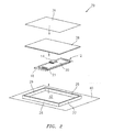
FIG. 2 is a pictorial illustration of a second embodiment of an RFID tag system; -
FIG. 3 is a cross-sectional illustration of the RFID tag system ofFIG. 1 including a metallic backplane; -
FIG. 4 is a cross-sectional illustration of an RFID tag system ofFIG. 1 without the metallic backplane and mounted on a metallic surface; -
FIG. 5 is a cross-sectional illustration of the RFID tag system illustrated inFIG. 2 ; and -
FIG. 6 is a schematic illustration of an equivalent electrical circuit representation of an RFID reader electromagnetically coupled to RFID tag system ofFIG. 1 ; -
FIG. 1 is a first embodiment of anRFID tag system 10. The system includes anRFID tag 12, which comprises an integratedcircuit 14 that may be mounted to a printedcircuit board 16, and anantenna 18 mounted on opposing sides of the printedcircuit board 16. Theantenna 18 includes afirst plate 20 located on a first side on the printed circuit board, and asecond plate 21 located on an opposite surface of the printedcircuit board 16 parallel to thefirst plate 20. The first andsecond plates second plate 21 is electrically connected to a metallic backplane 22 (e.g., Cu, Al, Au, et cetera). - The
RFID tag 12 may be placed within ahousing 24, which includes sidewalls 26-29 that form a recess. The sidewalls 26-29 may be formed from a dielectric material such as for example a ceramic, and the housing may include ahousing base surface 32 that may also be formed from a dielectric or thermal paper. Thehousing 24 may be mounted to a metallic ornon-metallic product surface 34, such as for example a surface of a gas turbine engine or a component part thereof. In one embodiment, the housing may be about 3.5 inches x 5 inches (88.9 x 127 mm), which is a size of a conventional data plate holder used my gas turbine engine manufacturers. Another conventional housing size is 2 inches x 1 inch (50.8 x 25.4 mm). In this embodiment themetal backplane 22 is arranged between theantenna 18 and thehousing base surface 32. - The
RFID tag system 10 also includes a metal cover plate/surface 36 that is positioned over and physically separated from theRFID tag 12 located within the recess of thehousing 24. The plate/surface 36 may be secured to the housing via threaded fasteners located in each of the corners of the housing. The fasteners preferably electrically insulate the housing from the plate/surface 36. For example, the fastener may include a metallic screw with a PFTE washer such a TEFLON® washer. However, it is contemplated that the fasteners may also be metallic to shunt to the plate/surface 36 to themetallic backplane 22. TheRFID tag 12 and themetal plate 36 are electromagnetically coupled when exposed to a radiating RF reader, and tuned to operate over a wide frequency range, such as for example about 840 to 960 MHz, 860 to 960 MHz, 900 to 960 MHz, or 860 to 930 Mhz. The system may also include adielectric spacer substrate 38 that physically separates the integratedcircuit 14 and themetal cover plate 36. The dielectric spacer substrate may be a foam, a thermal insulator for high temperature operation, air, et cetera. -
FIG. 2 illustrates a second embodiment of anRFID tag system 39. The system ofFIG. 2 is substantially the same as the system illustrated inFIG. 1 , with the principal exception that the system inFIG. 2 does not include ametal backplane 22 illustrated inFIG. 1 . In the embodiment of theFIG. 2 , thehousing base surface 32 contacts ametallic surface 40. -
FIG. 3 is a cross-sectional illustration of theRFID tag system 10 ofFIG. 1 . In this embodiment, since thesystem 10 includes themetallic backplane 22, theproduct mounting surface 34 may be metallic or non-metallic. -
FIG. 4 is a cross-sectional illustration of anRFID tag system 52. This embodiment is substantially the same as the embodiment illustrated inFIG. 3 with the principal exception that the RFID tag system does not have to be coupled to a surface, such as mountingsurface 34 illustrated inFIG. 3 . -
FIG. 5 is cross-sectional illustration of theRFID tag system 39 illustrated inFIG. 2 . In this embodiment thebase surface 32 of thehousing 24 connects to mountingsurface 40, which is metallic. -
FIG. 6 is a schematic illustration of an equivalent electrical circuit representation of an RFID reader electromagnetically coupled to theRFID tag system 10. The RFID tag reader radiates an RF signal, which the RFID tag receives and converts to an electrical signal. Thus in this equivalent electrical circuit representation the RFID reader is electrically represented by a signal source 60. Themetal plate 36 is represented by itscapacitance value Cp 62. The equivalent electrical circuit representation of theRFID tag 12 includes components for the antenna and the integrated circuit, both of which are equivalently illustrated inFIG. 6 . The antenna has an impedance that includes a serially connectedresistance R A 64 andinductance L A 66. Theintegrated circuit 14 is represented by an impedance shown ascapacitance C I 68 and aresistance R I 70, which are shown in electrical series. The metal surface/cover provides the capacitance Cp that the may be used to tune the system to operate within the desired wide band frequency range. For example, the metal surface/cover provides a second pole in the RFID tag system response. - In addition to the capacitance Cp provided by the metal surface/cover 36 (
FIG. 1 ), the system response may be tuned using by adjusting the shape of the antenna (e.g., placing notch on the top plate 20), adjusting the distance between surfaces, the surface area of metal surfaces that provide a capacitance, et cetera. - Although this invention has been shown and described with respect to the detailed embodiments thereof, it will be understood by those skilled in the art that various changes in form and detail thereof may be made without departing from the scope of the claimed invention.
Claims (15)
- An RFID tag system (10;39), comprising:a housing (24) that includes an enclosed sidewall (26...29) and forms a recess with a housing base surface (32), where the housing (24) is configured and arranged to be mounted to a mounting surface (34;40);an RFID tag (12) within the housing (24), where the RFID tag (12) comprises an integrated circuit (16) and an antenna (18);where the housing base surface (32) separates the antenna (18) and the mounting surface (34;40); anda metal surface (36) secured to a top surface of the sidewall (26...29) to cover the recess, where the metal surface (36) and a transmission path from the integrated circuit (16) to the antenna (18) are electromagnetically coupled and tuned to operate across a wide band frequency range.
- The RFID tag system of claim 1, further comprising a metal backplane (22).
- The RFID tag system of claim 2, where the metal backplane (22) comprises a high conductivity metal such as copper, aluminum or gold.
- The RFID tag system of any preceding claim, where the sidewall (26...29) comprises a dielectric.
- The RFID tag system of any preceding claim, where the sidewall (26...29) is selected from the group consisting of a polymer or a ceramic.
- The RFID tag system of any preceding claim, where the metal surface (36) is selected from a metal comprising copper, steel, aluminum or an alloy.
- The RFID tag system of any preceding claim, further comprising a dielectric spacer substrate (38) positioned between the RFID tag (12) and the metal surface (36).
- The RFID tag system of any preceding claim, where the housing base surface (32) comprises a dielectric.
- The RFID tag system of any preceding claim, where the housing base surface (32) comprises thermal paper.
- The RFID tag system of any preceding claim, where the metal surface (36) comprises a metal foil.
- The RFID tag system of any preceding claim, where the RFID tag (12) comprises a printed circuit board (16) to which the integrated circuit (16) and the antenna (18) are electrically connected together to form a passive RFID tag (12).
- The RFID tag system of claim 11, where the antenna (18) is located on first and second parallel planar surfaces of the printed circuit board (16).
- The RFID tag system of any preceding claim, wherein the housing (24) is secured to the mounting surface (34;40) with a plurality of dielectric fasteners.
- The RFID tag system of any of claims 1 to 12, wherein the housing (24) is secured to the mounting surface (34;40) with a plurality of fasteners that electrically short the metal surface (36) to the mounting surface (34;40).
- The RFID tag system of any preceding claim, where the mounting surface (34;40) comprises a metallic surface of a gas turbine engine.
Applications Claiming Priority (1)
| Application Number | Priority Date | Filing Date | Title |
|---|---|---|---|
| US13/149,391 US8899488B2 (en) | 2011-05-31 | 2011-05-31 | RFID tag system |
Publications (3)
| Publication Number | Publication Date |
|---|---|
| EP2530624A2 true EP2530624A2 (en) | 2012-12-05 |
| EP2530624A3 EP2530624A3 (en) | 2013-10-09 |
| EP2530624B1 EP2530624B1 (en) | 2016-07-27 |
Family
ID=46178464
Family Applications (1)
| Application Number | Title | Priority Date | Filing Date |
|---|---|---|---|
| EP12170070.2A Not-in-force EP2530624B1 (en) | 2011-05-31 | 2012-05-30 | RFID tag system |
Country Status (2)
| Country | Link |
|---|---|
| US (1) | US8899488B2 (en) |
| EP (1) | EP2530624B1 (en) |
Families Citing this family (3)
| Publication number | Priority date | Publication date | Assignee | Title |
|---|---|---|---|---|
| US20130062418A1 (en) * | 2011-04-06 | 2013-03-14 | Craig WEAKLEY | Rfid tag having coupled resonator loop with loading |
| US10392959B2 (en) * | 2012-06-05 | 2019-08-27 | General Electric Company | High temperature flame sensor |
| KR102296158B1 (en) * | 2017-03-28 | 2021-08-31 | 삼성전자주식회사 | Multi feeding antenna and electronic device having the same |
Family Cites Families (55)
| Publication number | Priority date | Publication date | Assignee | Title |
|---|---|---|---|---|
| US3327306A (en) | 1964-12-31 | 1967-06-20 | Gen Electric | Optimized input adaptive control method and system |
| US3747340A (en) | 1971-08-12 | 1973-07-24 | Ford Motor Co | Flame sensing system for a turbine engine |
| US4423594A (en) | 1981-06-01 | 1984-01-03 | United Technologies Corporation | Adaptive self-correcting control system |
| US4490791A (en) | 1982-04-19 | 1984-12-25 | Chandler Evans Inc. | Adaptive gas turbine acceleration control |
| US4566266A (en) | 1984-02-13 | 1986-01-28 | Dresser Industries, Inc. | Automatic temperature compensated fuel flow regulation |
| US4825639A (en) | 1987-07-08 | 1989-05-02 | United Technologies Corporation | Control method for a gas turbine engine |
| US5165845A (en) | 1991-11-08 | 1992-11-24 | United Technologies Corporation | Controlling stall margin in a gas turbine engine during acceleration |
| US5479340A (en) | 1993-09-20 | 1995-12-26 | Sematech, Inc. | Real time control of plasma etch utilizing multivariate statistical analysis |
| GB9520002D0 (en) | 1995-09-30 | 1995-12-06 | Rolls Royce Plc | Turbine engine control system |
| US6330483B1 (en) | 1999-05-07 | 2001-12-11 | The Boeing Company | Optimal control system |
| KR100758100B1 (en) * | 2000-07-19 | 2007-09-11 | 가부시키가이샤 하넥스 | RDF tag housing structure, RDF tag installation structure and RDF tag communication method |
| US7107127B2 (en) | 2001-02-27 | 2006-09-12 | Sikorsky Aircraft Corporation | Computationally efficient means for optimal control with control constraints |
| WO2003044353A1 (en) | 2001-11-15 | 2003-05-30 | Goodrich Pump & Engine Control Systems, Inc. | Method and apparatus for adaptive acceleration schedules in gas turbine engine control systems |
| US7216071B2 (en) | 2002-04-23 | 2007-05-08 | United Technologies Corporation | Hybrid gas turbine engine state variable model |
| US7219040B2 (en) | 2002-11-05 | 2007-05-15 | General Electric Company | Method and system for model based control of heavy duty gas turbine |
| US6823675B2 (en) | 2002-11-13 | 2004-11-30 | General Electric Company | Adaptive model-based control systems and methods for controlling a gas turbine |
| US6882889B2 (en) | 2002-12-02 | 2005-04-19 | United Technologies Corporation | Constrained dynamic inversion control algorithm |
| US7328074B2 (en) | 2002-12-02 | 2008-02-05 | United Technologies Corporation | Real-time quadratic programming for control of dynamical systems |
| US6940408B2 (en) | 2002-12-31 | 2005-09-06 | Avery Dennison Corporation | RFID device and method of forming |
| US7224280B2 (en) | 2002-12-31 | 2007-05-29 | Avery Dennison Corporation | RFID device and method of forming |
| US7225992B2 (en) | 2003-02-13 | 2007-06-05 | Avery Dennison Corporation | RFID device tester and method |
| US7152023B2 (en) | 2003-02-14 | 2006-12-19 | United Technologies Corporation | System and method of accelerated active set search for quadratic programming in real-time model predictive control |
| US20050193739A1 (en) | 2004-03-02 | 2005-09-08 | General Electric Company | Model-based control systems and methods for gas turbine engines |
| US7203554B2 (en) | 2004-03-16 | 2007-04-10 | United Technologies Corporation | Model predictive controller with life extending control |
| US20050282355A1 (en) | 2004-06-18 | 2005-12-22 | Edwards David N | High density bonding of electrical devices |
| US7688206B2 (en) | 2004-11-22 | 2010-03-30 | Alien Technology Corporation | Radio frequency identification (RFID) tag for an item having a conductive layer included or attached |
| US20060282177A1 (en) | 2005-06-10 | 2006-12-14 | United Technologies Corporation | System and method of applying interior point method for online model predictive control of gas turbine engines |
| US7603222B2 (en) | 2005-11-18 | 2009-10-13 | General Electric Company | Sensor diagnostics using embedded model quality parameters |
| US7504952B2 (en) * | 2005-12-28 | 2009-03-17 | Sandlinks Ltd. | Wide band RFID system with tag on flexible label |
| JP4890095B2 (en) | 2006-05-19 | 2012-03-07 | 株式会社Ihi | Stall sign detection device and method, and engine control system |
| US8794531B2 (en) * | 2006-07-13 | 2014-08-05 | Confidex Oy | Radio frequency identification tag |
| GB2440757B (en) | 2006-08-10 | 2008-12-24 | Rolls Royce Plc | Controlling fuel supply to a combustor of a gas turbine engine |
| US7837429B2 (en) | 2006-10-12 | 2010-11-23 | General Electric Company | Predictive model based control system for heavy duty gas turbines |
| WO2008079902A1 (en) | 2006-12-21 | 2008-07-03 | Neology, Inc. | Systems and methods for a rfid enabled metal license plate |
| US8050772B1 (en) | 2007-01-25 | 2011-11-01 | Advanced Neuromodulation Systems, Inc. | Burr hole caps and methods of use |
| US9043118B2 (en) | 2007-04-02 | 2015-05-26 | General Electric Company | Methods and systems for model-based control of gas turbines |
| US7908072B2 (en) | 2007-06-26 | 2011-03-15 | General Electric Company | Systems and methods for using a combustion dynamics tuning algorithm with a multi-can combustor |
| JP5104865B2 (en) | 2007-07-18 | 2012-12-19 | 株式会社村田製作所 | Wireless IC device |
| US20090043447A1 (en) | 2007-08-07 | 2009-02-12 | General Electric Company | Systems and Methods for Model-Based Sensor Fault Detection and Isolation |
| WO2009049312A1 (en) * | 2007-10-12 | 2009-04-16 | Solstice Medical, Llc. | Small gamma shielded shorted patch rfid tag |
| US7822512B2 (en) | 2008-01-08 | 2010-10-26 | General Electric Company | Methods and systems for providing real-time comparison with an alternate control strategy for a turbine |
| US20090256762A1 (en) | 2008-04-09 | 2009-10-15 | Rcd Technology, Inc. | Rfid antenna with quarter wavelength shunt |
| US7949416B2 (en) | 2008-05-06 | 2011-05-24 | United Technologies Corporation | Multivariable control system |
| US8073555B2 (en) | 2008-05-06 | 2011-12-06 | United Technologies Corporation | Basepoint estimator |
| US8078292B2 (en) | 2008-07-08 | 2011-12-13 | United Technologies Corporation | Basepoint estimator |
| US8484981B2 (en) | 2008-08-26 | 2013-07-16 | Siemens Energy, Inc. | Integrated fuel gas characterization system |
| US8523102B2 (en) | 2008-10-03 | 2013-09-03 | Textron Innovations Inc. | Method and apparatus for aircraft sensor and actuator failure protection using reconfigurable flight control laws |
| US8131384B2 (en) | 2008-11-03 | 2012-03-06 | United Technologies Corporation | Design and control of engineering systems utilizing component-level dynamic mathematical model with multiple-input multiple-output estimator |
| US8090456B2 (en) | 2008-11-03 | 2012-01-03 | United Technologies Corporation | System and method for design and control of engineering systems utilizing component-level dynamic mathematical model |
| US20100289626A1 (en) | 2009-03-25 | 2010-11-18 | Rcd Technology Inc. | Radio frequency identification (rfid) enabled inventory tray |
| US8668434B2 (en) | 2009-09-02 | 2014-03-11 | United Technologies Corporation | Robust flow parameter model for component-level dynamic turbine system control |
| US8925824B2 (en) | 2009-09-10 | 2015-01-06 | Thomas Craig Weakley | Radio frequency identification (RFID) antenna with tuning stubs for mount on metal RFID tag |
| US8215095B2 (en) | 2009-10-26 | 2012-07-10 | General Electric Company | Model-based coordinated air-fuel control for a gas turbine |
| US8171717B2 (en) | 2010-05-14 | 2012-05-08 | General Electric Company | Model-based coordinated air-fuel control for a gas turbine |
| US9342060B2 (en) | 2010-09-14 | 2016-05-17 | United Technologies Corporation | Adaptive control for a gas turbine engine |
-
2011
- 2011-05-31 US US13/149,391 patent/US8899488B2/en active Active
-
2012
- 2012-05-30 EP EP12170070.2A patent/EP2530624B1/en not_active Not-in-force
Non-Patent Citations (1)
| Title |
|---|
| None |
Also Published As
| Publication number | Publication date |
|---|---|
| US20120305652A1 (en) | 2012-12-06 |
| EP2530624A3 (en) | 2013-10-09 |
| US8899488B2 (en) | 2014-12-02 |
| EP2530624B1 (en) | 2016-07-27 |
Similar Documents
| Publication | Publication Date | Title |
|---|---|---|
| KR100960210B1 (en) | RDF tag and its manufacturing method | |
| JP4281683B2 (en) | IC tag mounting structure | |
| CN104092019B (en) | Wireless IC device and component for wireless IC device | |
| US10387764B2 (en) | RFID tag, article including the same, and RFID tag manufacturing method | |
| EP1493204B1 (en) | Multi-band planar antenna | |
| US20110227710A1 (en) | Rfid tag, rfid tag set and rfid system | |
| CN209525672U (en) | RFID tags | |
| US10552724B2 (en) | RFID tag and article having RFID tag attached thereto | |
| DE602005002046D1 (en) | COMPACT MULTI-BAND PIFA ANTENNA WITH A SHAFT-LINE SLOTTED BZW. WAVE-LINE SLICES | |
| EP2447887A2 (en) | Integrated PCB UHF RFID matching network/antenna | |
| US9147145B2 (en) | RFID tag system | |
| EP2530624B1 (en) | RFID tag system | |
| JP5199259B2 (en) | Tag antenna for tag and RFID tag using the same | |
| EP2659547B1 (en) | Mounting electronic components on an antenna structure | |
| US7932730B2 (en) | System for inspecting electromagnetic coupling modules and radio IC devices and method for manufacturing electromagnetic coupling modules and radio IC devices using the system | |
| JP6627627B2 (en) | RFID tag and high frequency circuit | |
| JP2010062941A (en) | Rfid tag, rfid system, and method for manufacturing rfid tag | |
| CN209712910U (en) | Articles with wireless communication tags and metal bodies with wireless communication tags | |
| CN105531722A (en) | Non-contact ic label | |
| JP2019197380A (en) | RF tag label and RF tag structure | |
| RU2654081C1 (en) | Rfid tag of registration mark | |
| CN115618913A (en) | An enhanced UHF antenna and platform fault-tolerant optimized RFID tag | |
| RU173877U1 (en) | RFID REGISTRATION LABEL | |
| US20140159962A1 (en) | Gridded antenna and method for manufacturing the same | |
| US20140313097A1 (en) | Gps antenna, motherboard employing same, and wireless communication device employing motherboard |
Legal Events
| Date | Code | Title | Description |
|---|---|---|---|
| PUAI | Public reference made under article 153(3) epc to a published international application that has entered the european phase |
Free format text: ORIGINAL CODE: 0009012 |
|
| AK | Designated contracting states |
Kind code of ref document: A2 Designated state(s): AL AT BE BG CH CY CZ DE DK EE ES FI FR GB GR HR HU IE IS IT LI LT LU LV MC MK MT NL NO PL PT RO RS SE SI SK SM TR |
|
| AX | Request for extension of the european patent |
Extension state: BA ME |
|
| PUAL | Search report despatched |
Free format text: ORIGINAL CODE: 0009013 |
|
| AK | Designated contracting states |
Kind code of ref document: A3 Designated state(s): AL AT BE BG CH CY CZ DE DK EE ES FI FR GB GR HR HU IE IS IT LI LT LU LV MC MK MT NL NO PL PT RO RS SE SI SK SM TR |
|
| AX | Request for extension of the european patent |
Extension state: BA ME |
|
| RIC1 | Information provided on ipc code assigned before grant |
Ipc: G06K 19/07 20060101AFI20130903BHEP Ipc: G06K 19/077 20060101ALI20130903BHEP |
|
| 17P | Request for examination filed |
Effective date: 20140331 |
|
| RBV | Designated contracting states (corrected) |
Designated state(s): AL AT BE BG CH CY CZ DE DK EE ES FI FR GB GR HR HU IE IS IT LI LT LU LV MC MK MT NL NO PL PT RO RS SE SI SK SM TR |
|
| 17Q | First examination report despatched |
Effective date: 20150623 |
|
| GRAP | Despatch of communication of intention to grant a patent |
Free format text: ORIGINAL CODE: EPIDOSNIGR1 |
|
| INTG | Intention to grant announced |
Effective date: 20160318 |
|
| GRAS | Grant fee paid |
Free format text: ORIGINAL CODE: EPIDOSNIGR3 |
|
| GRAA | (expected) grant |
Free format text: ORIGINAL CODE: 0009210 |
|
| AK | Designated contracting states |
Kind code of ref document: B1 Designated state(s): AL AT BE BG CH CY CZ DE DK EE ES FI FR GB GR HR HU IE IS IT LI LT LU LV MC MK MT NL NO PL PT RO RS SE SI SK SM TR |
|
| REG | Reference to a national code |
Ref country code: GB Ref legal event code: FG4D |
|
| REG | Reference to a national code |
Ref country code: CH Ref legal event code: EP |
|
| REG | Reference to a national code |
Ref country code: AT Ref legal event code: REF Ref document number: 816316 Country of ref document: AT Kind code of ref document: T Effective date: 20160815 |
|
| REG | Reference to a national code |
Ref country code: IE Ref legal event code: FG4D |
|
| REG | Reference to a national code |
Ref country code: DE Ref legal event code: R096 Ref document number: 602012020919 Country of ref document: DE |
|
| REG | Reference to a national code |
Ref country code: CH Ref legal event code: PCOW Free format text: NEW ADDRESS: 10 FARM SPRINGS RD., FARMINGTON, CT 06032 (US) |
|
| RAP2 | Party data changed (patent owner data changed or rights of a patent transferred) |
Owner name: UNITED TECHNOLOGIES CORPORATION |
|
| REG | Reference to a national code |
Ref country code: LT Ref legal event code: MG4D |
|
| REG | Reference to a national code |
Ref country code: NL Ref legal event code: MP Effective date: 20160727 |
|
| REG | Reference to a national code |
Ref country code: AT Ref legal event code: MK05 Ref document number: 816316 Country of ref document: AT Kind code of ref document: T Effective date: 20160727 |
|
| PG25 | Lapsed in a contracting state [announced via postgrant information from national office to epo] |
Ref country code: HR Free format text: LAPSE BECAUSE OF FAILURE TO SUBMIT A TRANSLATION OF THE DESCRIPTION OR TO PAY THE FEE WITHIN THE PRESCRIBED TIME-LIMIT Effective date: 20160727 Ref country code: RS Free format text: LAPSE BECAUSE OF FAILURE TO SUBMIT A TRANSLATION OF THE DESCRIPTION OR TO PAY THE FEE WITHIN THE PRESCRIBED TIME-LIMIT Effective date: 20160727 Ref country code: NL Free format text: LAPSE BECAUSE OF FAILURE TO SUBMIT A TRANSLATION OF THE DESCRIPTION OR TO PAY THE FEE WITHIN THE PRESCRIBED TIME-LIMIT Effective date: 20160727 Ref country code: FI Free format text: LAPSE BECAUSE OF FAILURE TO SUBMIT A TRANSLATION OF THE DESCRIPTION OR TO PAY THE FEE WITHIN THE PRESCRIBED TIME-LIMIT Effective date: 20160727 Ref country code: IS Free format text: LAPSE BECAUSE OF FAILURE TO SUBMIT A TRANSLATION OF THE DESCRIPTION OR TO PAY THE FEE WITHIN THE PRESCRIBED TIME-LIMIT Effective date: 20161127 Ref country code: IT Free format text: LAPSE BECAUSE OF FAILURE TO SUBMIT A TRANSLATION OF THE DESCRIPTION OR TO PAY THE FEE WITHIN THE PRESCRIBED TIME-LIMIT Effective date: 20160727 Ref country code: LT Free format text: LAPSE BECAUSE OF FAILURE TO SUBMIT A TRANSLATION OF THE DESCRIPTION OR TO PAY THE FEE WITHIN THE PRESCRIBED TIME-LIMIT Effective date: 20160727 Ref country code: NO Free format text: LAPSE BECAUSE OF FAILURE TO SUBMIT A TRANSLATION OF THE DESCRIPTION OR TO PAY THE FEE WITHIN THE PRESCRIBED TIME-LIMIT Effective date: 20161027 |
|
| PG25 | Lapsed in a contracting state [announced via postgrant information from national office to epo] |
Ref country code: PL Free format text: LAPSE BECAUSE OF FAILURE TO SUBMIT A TRANSLATION OF THE DESCRIPTION OR TO PAY THE FEE WITHIN THE PRESCRIBED TIME-LIMIT Effective date: 20160727 Ref country code: SE Free format text: LAPSE BECAUSE OF FAILURE TO SUBMIT A TRANSLATION OF THE DESCRIPTION OR TO PAY THE FEE WITHIN THE PRESCRIBED TIME-LIMIT Effective date: 20160727 Ref country code: ES Free format text: LAPSE BECAUSE OF FAILURE TO SUBMIT A TRANSLATION OF THE DESCRIPTION OR TO PAY THE FEE WITHIN THE PRESCRIBED TIME-LIMIT Effective date: 20160727 Ref country code: LV Free format text: LAPSE BECAUSE OF FAILURE TO SUBMIT A TRANSLATION OF THE DESCRIPTION OR TO PAY THE FEE WITHIN THE PRESCRIBED TIME-LIMIT Effective date: 20160727 Ref country code: GR Free format text: LAPSE BECAUSE OF FAILURE TO SUBMIT A TRANSLATION OF THE DESCRIPTION OR TO PAY THE FEE WITHIN THE PRESCRIBED TIME-LIMIT Effective date: 20161028 Ref country code: AT Free format text: LAPSE BECAUSE OF FAILURE TO SUBMIT A TRANSLATION OF THE DESCRIPTION OR TO PAY THE FEE WITHIN THE PRESCRIBED TIME-LIMIT Effective date: 20160727 Ref country code: PT Free format text: LAPSE BECAUSE OF FAILURE TO SUBMIT A TRANSLATION OF THE DESCRIPTION OR TO PAY THE FEE WITHIN THE PRESCRIBED TIME-LIMIT Effective date: 20161128 Ref country code: BE Free format text: LAPSE BECAUSE OF FAILURE TO SUBMIT A TRANSLATION OF THE DESCRIPTION OR TO PAY THE FEE WITHIN THE PRESCRIBED TIME-LIMIT Effective date: 20160727 |
|
| REG | Reference to a national code |
Ref country code: FR Ref legal event code: PLFP Year of fee payment: 6 |
|
| PG25 | Lapsed in a contracting state [announced via postgrant information from national office to epo] |
Ref country code: RO Free format text: LAPSE BECAUSE OF FAILURE TO SUBMIT A TRANSLATION OF THE DESCRIPTION OR TO PAY THE FEE WITHIN THE PRESCRIBED TIME-LIMIT Effective date: 20160727 Ref country code: EE Free format text: LAPSE BECAUSE OF FAILURE TO SUBMIT A TRANSLATION OF THE DESCRIPTION OR TO PAY THE FEE WITHIN THE PRESCRIBED TIME-LIMIT Effective date: 20160727 |
|
| REG | Reference to a national code |
Ref country code: DE Ref legal event code: R097 Ref document number: 602012020919 Country of ref document: DE |
|
| PG25 | Lapsed in a contracting state [announced via postgrant information from national office to epo] |
Ref country code: SK Free format text: LAPSE BECAUSE OF FAILURE TO SUBMIT A TRANSLATION OF THE DESCRIPTION OR TO PAY THE FEE WITHIN THE PRESCRIBED TIME-LIMIT Effective date: 20160727 Ref country code: BG Free format text: LAPSE BECAUSE OF FAILURE TO SUBMIT A TRANSLATION OF THE DESCRIPTION OR TO PAY THE FEE WITHIN THE PRESCRIBED TIME-LIMIT Effective date: 20161027 Ref country code: SM Free format text: LAPSE BECAUSE OF FAILURE TO SUBMIT A TRANSLATION OF THE DESCRIPTION OR TO PAY THE FEE WITHIN THE PRESCRIBED TIME-LIMIT Effective date: 20160727 Ref country code: CZ Free format text: LAPSE BECAUSE OF FAILURE TO SUBMIT A TRANSLATION OF THE DESCRIPTION OR TO PAY THE FEE WITHIN THE PRESCRIBED TIME-LIMIT Effective date: 20160727 Ref country code: DK Free format text: LAPSE BECAUSE OF FAILURE TO SUBMIT A TRANSLATION OF THE DESCRIPTION OR TO PAY THE FEE WITHIN THE PRESCRIBED TIME-LIMIT Effective date: 20160727 |
|
| PLBE | No opposition filed within time limit |
Free format text: ORIGINAL CODE: 0009261 |
|
| STAA | Information on the status of an ep patent application or granted ep patent |
Free format text: STATUS: NO OPPOSITION FILED WITHIN TIME LIMIT |
|
| 26N | No opposition filed |
Effective date: 20170502 |
|
| REG | Reference to a national code |
Ref country code: DE Ref legal event code: R082 Ref document number: 602012020919 Country of ref document: DE Representative=s name: SCHMITT-NILSON SCHRAUD WAIBEL WOHLFROM PATENTA, DE |
|
| PG25 | Lapsed in a contracting state [announced via postgrant information from national office to epo] |
Ref country code: SI Free format text: LAPSE BECAUSE OF FAILURE TO SUBMIT A TRANSLATION OF THE DESCRIPTION OR TO PAY THE FEE WITHIN THE PRESCRIBED TIME-LIMIT Effective date: 20160727 Ref country code: LU Free format text: LAPSE BECAUSE OF NON-PAYMENT OF DUE FEES Effective date: 20170531 |
|
| REG | Reference to a national code |
Ref country code: CH Ref legal event code: PL |
|
| PG25 | Lapsed in a contracting state [announced via postgrant information from national office to epo] |
Ref country code: MC Free format text: LAPSE BECAUSE OF FAILURE TO SUBMIT A TRANSLATION OF THE DESCRIPTION OR TO PAY THE FEE WITHIN THE PRESCRIBED TIME-LIMIT Effective date: 20160727 |
|
| REG | Reference to a national code |
Ref country code: IE Ref legal event code: MM4A |
|
| PG25 | Lapsed in a contracting state [announced via postgrant information from national office to epo] |
Ref country code: LI Free format text: LAPSE BECAUSE OF NON-PAYMENT OF DUE FEES Effective date: 20170531 Ref country code: CH Free format text: LAPSE BECAUSE OF NON-PAYMENT OF DUE FEES Effective date: 20170531 |
|
| PG25 | Lapsed in a contracting state [announced via postgrant information from national office to epo] |
Ref country code: LU Free format text: LAPSE BECAUSE OF NON-PAYMENT OF DUE FEES Effective date: 20170530 |
|
| REG | Reference to a national code |
Ref country code: FR Ref legal event code: PLFP Year of fee payment: 7 |
|
| PG25 | Lapsed in a contracting state [announced via postgrant information from national office to epo] |
Ref country code: IE Free format text: LAPSE BECAUSE OF NON-PAYMENT OF DUE FEES Effective date: 20170530 |
|
| PG25 | Lapsed in a contracting state [announced via postgrant information from national office to epo] |
Ref country code: MT Free format text: LAPSE BECAUSE OF NON-PAYMENT OF DUE FEES Effective date: 20170530 |
|
| PG25 | Lapsed in a contracting state [announced via postgrant information from national office to epo] |
Ref country code: AL Free format text: LAPSE BECAUSE OF FAILURE TO SUBMIT A TRANSLATION OF THE DESCRIPTION OR TO PAY THE FEE WITHIN THE PRESCRIBED TIME-LIMIT Effective date: 20160727 |
|
| PG25 | Lapsed in a contracting state [announced via postgrant information from national office to epo] |
Ref country code: HU Free format text: LAPSE BECAUSE OF FAILURE TO SUBMIT A TRANSLATION OF THE DESCRIPTION OR TO PAY THE FEE WITHIN THE PRESCRIBED TIME-LIMIT; INVALID AB INITIO Effective date: 20120530 |
|
| PG25 | Lapsed in a contracting state [announced via postgrant information from national office to epo] |
Ref country code: CY Free format text: LAPSE BECAUSE OF NON-PAYMENT OF DUE FEES Effective date: 20160727 |
|
| PG25 | Lapsed in a contracting state [announced via postgrant information from national office to epo] |
Ref country code: MK Free format text: LAPSE BECAUSE OF FAILURE TO SUBMIT A TRANSLATION OF THE DESCRIPTION OR TO PAY THE FEE WITHIN THE PRESCRIBED TIME-LIMIT Effective date: 20160727 |
|
| PG25 | Lapsed in a contracting state [announced via postgrant information from national office to epo] |
Ref country code: TR Free format text: LAPSE BECAUSE OF FAILURE TO SUBMIT A TRANSLATION OF THE DESCRIPTION OR TO PAY THE FEE WITHIN THE PRESCRIBED TIME-LIMIT Effective date: 20160727 |
|
| REG | Reference to a national code |
Ref country code: DE Ref legal event code: R081 Ref document number: 602012020919 Country of ref document: DE Owner name: RAYTHEON TECHNOLOGIES CORPORATION (N.D.GES.D.S, US Free format text: FORMER OWNER: UNITED TECHNOLOGIES CORPORATION, HARTFORD, CONN., US |
|
| P01 | Opt-out of the competence of the unified patent court (upc) registered |
Effective date: 20230520 |
|
| PGFP | Annual fee paid to national office [announced via postgrant information from national office to epo] |
Ref country code: GB Payment date: 20240419 Year of fee payment: 13 |
|
| PGFP | Annual fee paid to national office [announced via postgrant information from national office to epo] |
Ref country code: DE Payment date: 20240418 Year of fee payment: 13 |
|
| PGFP | Annual fee paid to national office [announced via postgrant information from national office to epo] |
Ref country code: FR Payment date: 20240418 Year of fee payment: 13 |
|
| REG | Reference to a national code |
Ref country code: DE Ref legal event code: R119 Ref document number: 602012020919 Country of ref document: DE |
|
| GBPC | Gb: european patent ceased through non-payment of renewal fee |
Effective date: 20250530 |
|
| PG25 | Lapsed in a contracting state [announced via postgrant information from national office to epo] |
Ref country code: GB Free format text: LAPSE BECAUSE OF NON-PAYMENT OF DUE FEES Effective date: 20250530 |
|
| PG25 | Lapsed in a contracting state [announced via postgrant information from national office to epo] |
Ref country code: DE Free format text: LAPSE BECAUSE OF NON-PAYMENT OF DUE FEES Effective date: 20251202 |
|
| PG25 | Lapsed in a contracting state [announced via postgrant information from national office to epo] |
Ref country code: FR Free format text: LAPSE BECAUSE OF NON-PAYMENT OF DUE FEES Effective date: 20250531 |