EP2530512A1 - Display device and method of display - Google Patents
Display device and method of display Download PDFInfo
- Publication number
- EP2530512A1 EP2530512A1 EP11736847A EP11736847A EP2530512A1 EP 2530512 A1 EP2530512 A1 EP 2530512A1 EP 11736847 A EP11736847 A EP 11736847A EP 11736847 A EP11736847 A EP 11736847A EP 2530512 A1 EP2530512 A1 EP 2530512A1
- Authority
- EP
- European Patent Office
- Prior art keywords
- display
- data
- video data
- liquid crystal
- video
- Prior art date
- Legal status (The legal status is an assumption and is not a legal conclusion. Google has not performed a legal analysis and makes no representation as to the accuracy of the status listed.)
- Withdrawn
Links
Images



Classifications
-
- G—PHYSICS
- G09—EDUCATION; CRYPTOGRAPHY; DISPLAY; ADVERTISING; SEALS
- G09G—ARRANGEMENTS OR CIRCUITS FOR CONTROL OF INDICATING DEVICES USING STATIC MEANS TO PRESENT VARIABLE INFORMATION
- G09G3/00—Control arrangements or circuits, of interest only in connection with visual indicators other than cathode-ray tubes
- G09G3/20—Control arrangements or circuits, of interest only in connection with visual indicators other than cathode-ray tubes for presentation of an assembly of a number of characters, e.g. a page, by composing the assembly by combination of individual elements arranged in a matrix no fixed position being assigned to or needed to be assigned to the individual characters or partial characters
- G09G3/34—Control arrangements or circuits, of interest only in connection with visual indicators other than cathode-ray tubes for presentation of an assembly of a number of characters, e.g. a page, by composing the assembly by combination of individual elements arranged in a matrix no fixed position being assigned to or needed to be assigned to the individual characters or partial characters by control of light from an independent source
- G09G3/3406—Control of illumination source
- G09G3/342—Control of illumination source using several illumination sources separately controlled corresponding to different display panel areas, e.g. along one dimension such as lines
-
- G—PHYSICS
- G02—OPTICS
- G02F—OPTICAL DEVICES OR ARRANGEMENTS FOR THE CONTROL OF LIGHT BY MODIFICATION OF THE OPTICAL PROPERTIES OF THE MEDIA OF THE ELEMENTS INVOLVED THEREIN; NON-LINEAR OPTICS; FREQUENCY-CHANGING OF LIGHT; OPTICAL LOGIC ELEMENTS; OPTICAL ANALOGUE/DIGITAL CONVERTERS
- G02F1/00—Devices or arrangements for the control of the intensity, colour, phase, polarisation or direction of light arriving from an independent light source, e.g. switching, gating or modulating; Non-linear optics
- G02F1/01—Devices or arrangements for the control of the intensity, colour, phase, polarisation or direction of light arriving from an independent light source, e.g. switching, gating or modulating; Non-linear optics for the control of the intensity, phase, polarisation or colour
- G02F1/13—Devices or arrangements for the control of the intensity, colour, phase, polarisation or direction of light arriving from an independent light source, e.g. switching, gating or modulating; Non-linear optics for the control of the intensity, phase, polarisation or colour based on liquid crystals, e.g. single liquid crystal display cells
- G02F1/133—Constructional arrangements; Operation of liquid crystal cells; Circuit arrangements
-
- G—PHYSICS
- G02—OPTICS
- G02B—OPTICAL ELEMENTS, SYSTEMS OR APPARATUS
- G02B30/00—Optical systems or apparatus for producing three-dimensional [3D] effects, e.g. stereoscopic images
- G02B30/20—Optical systems or apparatus for producing three-dimensional [3D] effects, e.g. stereoscopic images by providing first and second parallax images to an observer's left and right eyes
- G02B30/26—Optical systems or apparatus for producing three-dimensional [3D] effects, e.g. stereoscopic images by providing first and second parallax images to an observer's left and right eyes of the autostereoscopic type
- G02B30/27—Optical systems or apparatus for producing three-dimensional [3D] effects, e.g. stereoscopic images by providing first and second parallax images to an observer's left and right eyes of the autostereoscopic type involving lenticular arrays
-
- G—PHYSICS
- G09—EDUCATION; CRYPTOGRAPHY; DISPLAY; ADVERTISING; SEALS
- G09G—ARRANGEMENTS OR CIRCUITS FOR CONTROL OF INDICATING DEVICES USING STATIC MEANS TO PRESENT VARIABLE INFORMATION
- G09G3/00—Control arrangements or circuits, of interest only in connection with visual indicators other than cathode-ray tubes
- G09G3/001—Control arrangements or circuits, of interest only in connection with visual indicators other than cathode-ray tubes using specific devices not provided for in groups G09G3/02 - G09G3/36, e.g. using an intermediate record carrier such as a film slide; Projection systems; Display of non-alphanumerical information, solely or in combination with alphanumerical information, e.g. digital display on projected diapositive as background
- G09G3/003—Control arrangements or circuits, of interest only in connection with visual indicators other than cathode-ray tubes using specific devices not provided for in groups G09G3/02 - G09G3/36, e.g. using an intermediate record carrier such as a film slide; Projection systems; Display of non-alphanumerical information, solely or in combination with alphanumerical information, e.g. digital display on projected diapositive as background to produce spatial visual effects
-
- G—PHYSICS
- G09—EDUCATION; CRYPTOGRAPHY; DISPLAY; ADVERTISING; SEALS
- G09G—ARRANGEMENTS OR CIRCUITS FOR CONTROL OF INDICATING DEVICES USING STATIC MEANS TO PRESENT VARIABLE INFORMATION
- G09G3/00—Control arrangements or circuits, of interest only in connection with visual indicators other than cathode-ray tubes
- G09G3/20—Control arrangements or circuits, of interest only in connection with visual indicators other than cathode-ray tubes for presentation of an assembly of a number of characters, e.g. a page, by composing the assembly by combination of individual elements arranged in a matrix no fixed position being assigned to or needed to be assigned to the individual characters or partial characters
- G09G3/34—Control arrangements or circuits, of interest only in connection with visual indicators other than cathode-ray tubes for presentation of an assembly of a number of characters, e.g. a page, by composing the assembly by combination of individual elements arranged in a matrix no fixed position being assigned to or needed to be assigned to the individual characters or partial characters by control of light from an independent source
- G09G3/36—Control arrangements or circuits, of interest only in connection with visual indicators other than cathode-ray tubes for presentation of an assembly of a number of characters, e.g. a page, by composing the assembly by combination of individual elements arranged in a matrix no fixed position being assigned to or needed to be assigned to the individual characters or partial characters by control of light from an independent source using liquid crystals
-
- G—PHYSICS
- G09—EDUCATION; CRYPTOGRAPHY; DISPLAY; ADVERTISING; SEALS
- G09G—ARRANGEMENTS OR CIRCUITS FOR CONTROL OF INDICATING DEVICES USING STATIC MEANS TO PRESENT VARIABLE INFORMATION
- G09G3/00—Control arrangements or circuits, of interest only in connection with visual indicators other than cathode-ray tubes
- G09G3/20—Control arrangements or circuits, of interest only in connection with visual indicators other than cathode-ray tubes for presentation of an assembly of a number of characters, e.g. a page, by composing the assembly by combination of individual elements arranged in a matrix no fixed position being assigned to or needed to be assigned to the individual characters or partial characters
- G09G3/34—Control arrangements or circuits, of interest only in connection with visual indicators other than cathode-ray tubes for presentation of an assembly of a number of characters, e.g. a page, by composing the assembly by combination of individual elements arranged in a matrix no fixed position being assigned to or needed to be assigned to the individual characters or partial characters by control of light from an independent source
- G09G3/36—Control arrangements or circuits, of interest only in connection with visual indicators other than cathode-ray tubes for presentation of an assembly of a number of characters, e.g. a page, by composing the assembly by combination of individual elements arranged in a matrix no fixed position being assigned to or needed to be assigned to the individual characters or partial characters by control of light from an independent source using liquid crystals
- G09G3/3611—Control of matrices with row and column drivers
- G09G3/3648—Control of matrices with row and column drivers using an active matrix
-
- H—ELECTRICITY
- H04—ELECTRIC COMMUNICATION TECHNIQUE
- H04N—PICTORIAL COMMUNICATION, e.g. TELEVISION
- H04N13/00—Stereoscopic video systems; Multi-view video systems; Details thereof
- H04N13/30—Image reproducers
- H04N13/332—Displays for viewing with the aid of special glasses or head-mounted displays [HMD]
- H04N13/337—Displays for viewing with the aid of special glasses or head-mounted displays [HMD] using polarisation multiplexing
-
- H—ELECTRICITY
- H04—ELECTRIC COMMUNICATION TECHNIQUE
- H04N—PICTORIAL COMMUNICATION, e.g. TELEVISION
- H04N13/00—Stereoscopic video systems; Multi-view video systems; Details thereof
- H04N13/30—Image reproducers
- H04N13/332—Displays for viewing with the aid of special glasses or head-mounted displays [HMD]
- H04N13/341—Displays for viewing with the aid of special glasses or head-mounted displays [HMD] using temporal multiplexing
-
- H—ELECTRICITY
- H04—ELECTRIC COMMUNICATION TECHNIQUE
- H04N—PICTORIAL COMMUNICATION, e.g. TELEVISION
- H04N13/00—Stereoscopic video systems; Multi-view video systems; Details thereof
- H04N13/30—Image reproducers
- H04N13/398—Synchronisation thereof; Control thereof
-
- G—PHYSICS
- G02—OPTICS
- G02F—OPTICAL DEVICES OR ARRANGEMENTS FOR THE CONTROL OF LIGHT BY MODIFICATION OF THE OPTICAL PROPERTIES OF THE MEDIA OF THE ELEMENTS INVOLVED THEREIN; NON-LINEAR OPTICS; FREQUENCY-CHANGING OF LIGHT; OPTICAL LOGIC ELEMENTS; OPTICAL ANALOGUE/DIGITAL CONVERTERS
- G02F1/00—Devices or arrangements for the control of the intensity, colour, phase, polarisation or direction of light arriving from an independent light source, e.g. switching, gating or modulating; Non-linear optics
- G02F1/01—Devices or arrangements for the control of the intensity, colour, phase, polarisation or direction of light arriving from an independent light source, e.g. switching, gating or modulating; Non-linear optics for the control of the intensity, phase, polarisation or colour
- G02F1/13—Devices or arrangements for the control of the intensity, colour, phase, polarisation or direction of light arriving from an independent light source, e.g. switching, gating or modulating; Non-linear optics for the control of the intensity, phase, polarisation or colour based on liquid crystals, e.g. single liquid crystal display cells
- G02F1/133—Constructional arrangements; Operation of liquid crystal cells; Circuit arrangements
- G02F1/1333—Constructional arrangements; Manufacturing methods
- G02F1/1335—Structural association of cells with optical devices, e.g. polarisers or reflectors
- G02F1/1336—Illuminating devices
- G02F1/133601—Illuminating devices for spatial active dimming
-
- G—PHYSICS
- G09—EDUCATION; CRYPTOGRAPHY; DISPLAY; ADVERTISING; SEALS
- G09G—ARRANGEMENTS OR CIRCUITS FOR CONTROL OF INDICATING DEVICES USING STATIC MEANS TO PRESENT VARIABLE INFORMATION
- G09G2310/00—Command of the display device
- G09G2310/02—Addressing, scanning or driving the display screen or processing steps related thereto
- G09G2310/0224—Details of interlacing
-
- G—PHYSICS
- G09—EDUCATION; CRYPTOGRAPHY; DISPLAY; ADVERTISING; SEALS
- G09G—ARRANGEMENTS OR CIRCUITS FOR CONTROL OF INDICATING DEVICES USING STATIC MEANS TO PRESENT VARIABLE INFORMATION
- G09G2310/00—Command of the display device
- G09G2310/02—Addressing, scanning or driving the display screen or processing steps related thereto
- G09G2310/024—Scrolling of light from the illumination source over the display in combination with the scanning of the display screen
-
- G—PHYSICS
- G09—EDUCATION; CRYPTOGRAPHY; DISPLAY; ADVERTISING; SEALS
- G09G—ARRANGEMENTS OR CIRCUITS FOR CONTROL OF INDICATING DEVICES USING STATIC MEANS TO PRESENT VARIABLE INFORMATION
- G09G2310/00—Command of the display device
- G09G2310/08—Details of timing specific for flat panels, other than clock recovery
-
- G—PHYSICS
- G09—EDUCATION; CRYPTOGRAPHY; DISPLAY; ADVERTISING; SEALS
- G09G—ARRANGEMENTS OR CIRCUITS FOR CONTROL OF INDICATING DEVICES USING STATIC MEANS TO PRESENT VARIABLE INFORMATION
- G09G2330/00—Aspects of power supply; Aspects of display protection and defect management
- G09G2330/02—Details of power systems and of start or stop of display operation
- G09G2330/021—Power management, e.g. power saving
-
- G—PHYSICS
- G09—EDUCATION; CRYPTOGRAPHY; DISPLAY; ADVERTISING; SEALS
- G09G—ARRANGEMENTS OR CIRCUITS FOR CONTROL OF INDICATING DEVICES USING STATIC MEANS TO PRESENT VARIABLE INFORMATION
- G09G2360/00—Aspects of the architecture of display systems
- G09G2360/18—Use of a frame buffer in a display terminal, inclusive of the display panel
Definitions
- the present invention relates to a display device and a display method adapted to implement the light emission control of a backlight unit disposed behind a liquid crystal panel.
- stereoscopic video techniques displaying on a liquid crystal panel a pair ofright and left video data (video data for the right eye and video data for the left eye) with binocular disparity, to make a viewer perceive as if 3D objects were present.
- various techniques to implement such a stereoscopic video display include, for instance, light polarizing filter systems (passive types) such as ⁇ pol and X pol ®, and electronic shutter systems (negative types).
- Stereoscopic video techniques using light polarizing filter systems utilize, for instance, two kinds of light polarizing filters different in polarization characteristic that are interlaced with each other (for every horizontal line) on a display screen of a liquid crystal panel. Then, a set of video data for the right eye is rendered on odd-numbered lines of the liquid crystal panel, where either kind of the light polarizing filters is disposed Also, a set of video data for the left eye is rendered on even-numbered lines of the liquid crystal panel, where the other kind of the light polarizing filters is disposed.
- a viewer can have visual contact through light polarizing eyeglasses with a right eye image rendered on every other one of the horizontal lines at the right eye and with a left eye image rendered on every other one of the horizontal lines at the left eye, thereby perceiving a stereoscopic picture with binocular disparity (for instance, Patent literature 1).
- the above-described stereoscopic video techniques using light polarizing filter systems are more excellent than the stereoscopic video techniques using electronic shutter systems in that they are free from the flickers of display images and the timings of image perception at the right and left eyes do not differ with each other.
- the resolution of perceivable image at either eye equals to approximately one half of a resolution of the entirety of the liquid crystal panel, thereby getting inferior to the stereoscopic video techniques using electronic shutter systems.
- Such a new technique needs not only the switching of display on a liquid crystal panel, but also the switching of the polarization characteristics of the light polarizing eyeglasses.
- the light emitting duration of a backlight unit irradiating the liquid crystal panel is simply lengthened to increase the luminance ofthe liquid crystal panel, crosstalk would occur between an arbitrary set of field data and an antecedent or subsequent set of field data different in content.
- the light emitting duration of the backlight unit is simply shortened, luminance would vary in the liquid crystal panel, or necessary luminance for display would not be obtained.
- the present invention has an object to provide a display device and a display method adapted to suppress the occurrence of crosstalk and ensure sufficient luminance through an adequate light emission control of a backlight unit. Solutions to the problem
- a display device comprising a liquid crystal panel configured with video display lines, a display controller configured to have display data rendered on the liquid crystal panel in a scan format, the display data comprising first field data of a video signal input, and second field data of the video signal as field data subsequent in temporal order and different in content from the first field data, a backlight unit disposed behind the liquid crystal panel, and configured with light sources adapted to emit light for irradiation to respective regions on the liquid crystal panel sectioned in accordance with a scan direction, and a backlight controller configured to have the light sources transitioned between a lights-out state and a light emitting state with a transition time shorter than a scan time of the first field data and a scan time of the second field data by the display controller.
- the backlight controller may well be configured to determine a light emission starting timing at a light source of the light sources that corresponds to an initial line in the video display lines of the liquid crystal panel, in dependence on a display ending timing of field data previous by one in temporal order, and to determine a light emission ending timing at a light source of the light sources that corresponds to a final line in the video display lines of the liquid crystal panel, in dependence on a display starting timing of field data subsequent in temporal order. Further, the backlight controller may well be configured to have light emitting durations of the light sources equalized to each other.
- the liquid crystal panel may well include a first display region with a prescribed polarization characteristic and a second display region different in polarization characteristic from the first display region, and further comprise a data acquiring interface configured to acquire a combination of video data for right eye and video data for left eye adapted to have a stereoscopic picture perceived with binocular disparity, a frame memory configured to hold the combination of video data for right eye and video data for left eye as acquired, and a display data producer configured to have the first field data obtained as a combination of video data corresponding to the first display region in the video data for right eye and video data corresponding to the second display region in the video data for left eye, and the second field data obtained as a combination of video data corresponding to the second display region in the video data for right eye and video data corresponding to the first display region in the video data for left eye, allocated alternately to produce the display data.
- a data acquiring interface configured to acquire a combination of video data for right eye and video data for left eye adapted to have a stereoscopic picture perceived with
- first display region and the second display region either may well comprise odd-numbered lines in the video display lines of the liquid crystal panel, the other comprising even-numbered lines in the video display lines.
- the display data producer may well be adapted to produce display data consisting of one of the first field data and the second field data.
- a display method comprising having display data rendered on a liquid crystal panel in a scan format, the display data comprising first field data of a video signal input, and second field data of the video signal as field data subsequent in temporal order and different in content from the first field data, and controlling a backlight unit disposed behind the liquid crystal panel, and configured with light sources adapted to emit light for irradiation to respective regions on the liquid crystal panel sectioned in accordance with a scan direction, to have the light sources transitioned between a lights-out state and a light emitting state with a transition time shorter than a scan time of the display data.
- the liquid crystal panel may well include a first display region with a prescribed polarization characteristic and a second display region different in polarization characteristic from the first display region
- the display method may well comprise acquiring a combination of video data for right eye and video data for left eye adapted to have a stereoscopic picture perceived with binocular disparity, and having the first field data obtained as a combination of video data in the video data for right eye corresponding to the first display region and video data in the video data for left eye corresponding to the second display region, and the second field data obtained as a combination of video data in the video data for right eye corresponding to the second display region and video data in the video data for left eye corresponding to the first display region, allocated alternately to produce the display data.
- a display device of the present invention through an adequate light emission control of a backlight unit, enables to suppress the occurrence of crosstalk between anterior and posterior field data different in content, secure a light emission duration at light sources in the backlight unit, and obtain sufficient luminance.
- Fig. 1 is an explanatory illustration showing general relations between constituent devices of a display system 100.
- the display system 100 includes a display device 110 and light-polarizing eyeglasses 120.
- the display device 110 is adapted to acquire stereoscopic video data (video data for the right eye and video data for the left eye) for use to have stereoscopic pictures perceived with binocular disparity, for instance, from a broadcasting station 112 through broadcasting airwaves, or from a server device 116 through a communication network 114 such as the Internet, a LAN or dedicated line, or else from a storage medium 118 such as a DVD, BD, or USB memory.
- the display device 110 renders the stereoscopic video data on a liquid crystal panel mounted thereon.
- the light-polarizing eyeglasses 120 have light-polarizing filters.
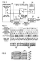
- a viewer wearing light-polarizing eyeglasses 120 has visual contact with video data for the right eye and video data for the left eye, both the video data being rendered on the display device 110, with the right eye and the left eye, respectively, thereby perceiving stereoscopic pictures with binocular disparity.
- Fig. 2 is a functional block diagram showing general functions of the display device 110.
- the display device 110 includes a data acquiring interface 150, a frame memory 152, a display data producer 154, a display controller 156, a liquid crystal panel 158, an infrared communication interface 160, a backlight unit 162, a backlight controller 164, and an operation interface 166.
- the data acquiring interface 150 is adapted to acquire frames of stereoscopic video data as video picture signals composed of a set of video data for the right eye and a set of video data for the left eye, for instance, at a frame frequency of 30Hz.
- the term 'frame' is referred to as the images constituting a video picture.
- an image constructed from a combination of these lines is referred to as a field. Therefore, the data acquiring interface 150 is adapted to acquire images in the forms of video data for the right eye and video data for the left eye, 30 pictures every second.
- the data acquiring interface 150 may be adapted to individually acquire a set of video data for the right eye and a set of video data for the left eye from different routes (circuit lines), or to acquire them as an integrated data set (for instance, data set with a side-by-side format) from a single route.
- the frame memory 152 includes a RAM, a flush memory, an HDD to temporarily hold video data for the right eye and video data for the left eye, which are acquired at the data acquiring interface 150. It is noted that the HDD, which is accurately a device, is handled in an equivalent sense to the other storage media for the convenience of description.
- the display data producer 154 is adapted to read a set of video data for the right eye and a set of video data for the left eye from the frame memory 152, and have a set of first field data and a set of second field data alternately allocated with a frequency (for instance, 60 Hz) twice as large as a frame frequency, thereby producing a set of display data.
- the set of first field data is obtained as a combination of a set of video data corresponding to a first display region in the set of video data for the right eye and a set of video data corresponding to a second display region in the set of video data for the left eye.
- the set of second field data is obtained as a combination of a set of video data corresponding to the second display region in the set of video data for the right eye and a set of video data corresponding to the first display region in the set of video data for the left eye. Also, the set of second field data is a set of field data subsequent in temporal order.
- the liquid crystal panel 158 has a number of video lines from an initial line to a final line, such that one of the first display region and the second display region corresponds to a set of odd lines (a set of odd-numbered horizontal lines) of the video display lines on the liquid crystal panel 158, and the other corresponds to a set of even lines (a set of even numbered horizontal lines) of the video display lines.
- the display data producer 154 is adapted to repeat producing a set of first field data and a set of second field data twice, respectively. That is, two sets of first field data and two sets of second field data are produced within a frame cycle (one frame). Accordingly, the field frequency is equal to four times a flame frequency (to be 120 Hz for a frame frequency of 30 Hz). Such arrangement allows for rendering a set of display data on the liquid crystal panel 158 with a reduced scan time (as a period of time from a scan start to a scan end).
- sets of field data will be referred to as "sets of field data different in content" to discriminate from a situation that a set of field data is repeated twice.
- Fig. 3 is a functional block diagram for explaining specific operations at the display data producer 154
- Fig. 4 is a timing chart showing those signals constituting bases of operation at the display data producer 154.
- the display data producer 154 has a counter 154a adapted to repeat incrementing its count value at each of edges (rising edges and falling edges) of horizontal synchronizing signals (refer to Fig. 4 ) at a rate represented by "a field frequency (for instance, 120 Hz)/2 ⁇ total number of horizontal lines (for instance, 1080)". Then the counter 154a resets the count value each time when it has reached the total number of horizontal lines.
- the counter 154a is operable to output an incremented count value to the frame memory 152 through a count signal.
- the counting from '1' to the total number of horizontal lines is repeated four times (corresponding to four sets of field data) within one cycle (one clock) of a vertical synchronizing signal (refer to Fig. 4 ).
- the frame memory 152 is operable to output horizontal lines of a set of video data for the right eye and a set of video data for the left eye, the respective horizontal lines corresponding to a count value indicated by the count signal, to a switch 154b in the display data producer 154.
- a set of video data for the right eye and a set of video data for the left eye are respectively output four times in a unit of horizontal line within a cycle of a vertical synchronizing signal.
- the display data producer 154 has an exclusive OR circuit 154c, which is operable to calculate an XOR between a horizontal synchronizing signal and a vertical synchronizing signal, thereby generating a video data switching signal (refer to Fig. 4 ) for use at the switch 154b to determine which video data should be output. Accordingly, the video data switching signal appears as a signal identical to the horizontal synchronizing signal when the vertical synchronizing signal is in a negative state, while appearing as a logical inverted signal of the horizontal synchronizing signal when the vertical synchronizing signal is in a positive state.
- the switch 154b is operable to sequentially input from the frame memory 152 horizontal lines corresponding to count values of video data for the right eye and video data for the left eye in parallel. Then the switch 154b is operated to output either horizontal line in accordance with a video data switching signal input from the exclusive OR circuit 154c. More specifically, the switch 154 is adapted to output a horizontal line of video data for the right eye when the video data switching signal is in a negative state and a horizontal line of video data for the left eye when the video data switching signal is in a positive state.
- a set of first field data 180 is produced twice consecutively.
- a set of second field data 182 is produced twice consecutively.
- the odd lines (first display regions) of each set of first field data 180 correspond to the odd lines of a set of video data for the right eye
- the even lines (second display regions) of each set of first field data 180 corresponding to the even lines of a set of video data for the left eye
- the odd lines of each set of second field data 182 correspond to the odd lines of the set of video data for the left eye
- the even lines of each set of second field data 182 corresponding to the even lines of the set of video data for the right eye.
- video data for the right eye and video data for the left eye that are once held at the frame memory 152 are taken out in sequence, respectively, to produce a set of display data composed of sets of first field data 180 and sets of second field data 182.
- video data for the right eye and video data for the left eye that are acquired through the data acquiring interface 150 may be directly processed at the display data producer 154 to hold in a frame memory 152 that may be rearranged at a subsequent stage of the display data producer 154.
- a set of first field data 180 and a set of second field data 182 may be alternately held in this frame memory 152 at a field frequency of 60 Hz, and the display controller 156 may read each of the sets of field data from the frame memory 152 twice to raise the field period to 120 Hz.
- the frame memory 152 can significantly reduce a capacity of the frame memory 152 by holding simply either a set of first field data 180 or a set of second field data 182, which has a data volume of half the sum of a set of video data for the right eye and a set of video data for the left eye, instead of holding both of the set of video data for the right eye and the set of video data for the left eye.
- the display controller 156 is adapted to have display data produced at the display data producer 154 rendered on the liquid crystal panel 158 sequentially in a scan format.
- the scan format (a progressive format, an interlaced format, etc.) is defined as a format for rendering data on the liquid crystal panel 158 in a unit of video display line (horizontal line) from the right to the left, and for repeating this in order from the top to the bottom to render a whole set of display data.
- the display controller 156 employs a progressive format for rendering display data on the liquid crystal panel 158.
- the liquid crystal panel 158 is configured with a liquid crystal composite sealed between two glass sheets to render display data on video display lines thereof with a control signal received from the display controller 156. Further, the liquid crystal panel 158 is configured with a display screen having two kinds of light polarizing filters different in polarization characteristic that are interlaced with each other (with an interval of one line).
- the phrase 'different in polarization characteristic' means that in use of light polarizing filters adapted for linear polarization, the polarization of one light polarizing filter is, for instance, perpendicular to that of the other polarizing filter.
- the phrase also means that in use of light polarizing filters adapted for circular polarization, one light polarizing filter has right-handed polarization and the other light polarizing filter has left-handed polarization.
- Fig. 5 is an explanatory illustration for explaining a configuration of display screen of the liquid crystal panel 158.
- a set of first filters with a certain polarization characteristic is formed on a part of display screen corresponding to odd-numbered (odd) lines 184 in the set of video display lines, constituting the first display region of the liquid crystal panel 158
- a set of second filters different in polarization characteristic from the set of first filters is formed on the other part of display screen corresponding to even-numbered (even) lines 186 in the set of video display lines, constituting the second display region of the liquid crystal panel 158.
- the filter formed on each odd line 184 in the set of video display lines is operable to give a phase difference of + ⁇ (wavelength)/4 to incident image light as linearly polarized light along an axis of polarization perpendicular to the horizontal direction, thereby outputting this as right-handed circularly polarized light.
- the filter formed on each even line 186 in the set of video display lines is operable to give a phase difference of - ⁇ /4 to incident image light, thereby outputting this as left-handed circularly polarized light.
- the fluxes of image lights of a set of video data for the right eye or video data for the left eye, transmitted through the set of first filters on odd lines 184, are opposite in a rotational direction of polarization to the fluxes of image lights of a set of video data for the right eye or video data for the left eye, transmitted through the set of second filters on even lines 186, as illustrated in the arrows of Fig. 5 .
- a set of first filters and a set of second filters may also be a combination of a set of first filters and a set of second filters, either being formed with a phase difference of a proportion of ⁇ /2 to output light linearly polarized light perpendicular to incident linearly polarized light, the other being made of simple glass or resin with substantially no phase difference, to make the polarization characteristic ofthe set of first filters different from that of the set of second filters.
- the infrared communication interface 160 is configured to establish infrared communications with the light polarizing eyeglasses 120, and to transmit vertical synchronizing signals illustrated in Fig. 4 to the light polarizing eyeglasses 120, in order to transmit timings for switching polarization characteristics.
- the display data producer 154 is adapted to produce sets of first field data 180 during a negative state of a vertical synchronizing signal, and sets of second field data 182 during a positive state of the vertical synchronizing signal.
- Each set of first field data 180 has odd lines allotted to a set of video data for the right eye and even lines allotted to a set of video data for the left eye.
- Each set of second field data 182 also has odd lines allotted to a set of video data for the left eye and even lines allotted to a set of video data for the right eye.
- a set of video data for the right eye is outputted through the set of first filters on a set of odd lines 184 in the liquid crystal panel 158, and a set of video data for the left eye is outputted through the set of second filters on a set of even lines 186 at the liquid crystal panel 158.
- a set of video data for the right eye is outputted through the set of second filters on the set of even lines 186, and a set of video data for the left eye is outputted through the set of first filters on the set of odd lines 184.
- the light polarizing eyeglasses 120 must serve to have the viewer's right eye visually contact with video data simply for the right eye, while having the viewer's left eye visually contact with video data simply for the left eye. Therefore, the light polarizing eyeglasses 120 are configured to receive a vertical synchronizing signal from the infrared communication interface 160 to control a combination of a light polarizing filter in a right eye window of the light polarizing eyeglasses 120, which corresponds to the right eye of a viewer, and a light polarizing filter in a left eye window of the light polarizing eyeglasses 120, which corresponds to the left eye, in accordance with the vertical synchronizing signal.
- the light polarizing filter in the right eye window is switched for transmitting fluxes of first linear-polarized light and for blocking out fluxes of second linear-polarized light perpendicular to the first linear-polarized light.
- the fluxes of first linear polarized light are obtained by giving a prescribed phase difference to fluxes of circularly polarized light outputted from the set of first filters on odd lines 184 in the set of video display lines of the liquid crystal panel 158
- the fluxes of second linear-polarized light are obtained by giving a prescribed phase difference to fluxes of circularly polarized light outputted from the set of second filters.
- the light polarizing filter in the left eye window is switched for transmitting fluxes of second linear-polarized light and for blocking out fluxes of first linear-polarized light perpendicular to the second linear-polarized light.
- the fluxes of second linear-polarized light are obtained by giving a prescribed phase difference to fluxes of circularly polarized light outputted from the set of second filters on even lines 186 in the set of video display lines of the liquid crystal panel 158
- the fluxes of first linear-polarized light are obtained by giving a prescribed phase difference to fluxes of circularly polarized light outputted from the set of first filters.
- the light polarizing filters in the right eye window and the left eye window are switched for exhibiting transmission characteristics opposite to those during the negative state, respectively.
- Fig. 6 is an explanatory illustration showing relations between sets of display data rendered on the liquid crystal panel 158 and images perceived through the light polarizing eyeglasses 120.
- a set of display data 190a is rendered on the liquid crystal panel 158 in order.
- the set of display data 190a has a set of video data for the right eye (designated by R in the figure) allocated on odd lines and a set of video data for the left eye (designated by L in the figure) allocated on even lines.
- a set of display data 190b is perceived at a viewer's right eye.
- the left eye window of the light polarizing eyeglasses 120 is adapted to transmit fluxes of linearly polarized light of even lines
- a set of display data 190c is perceived at the viewer's left eye.
- a set of display data 190d is rendered on the liquid crystal panel 158 in order.
- the set of display data 190d has a set of video data for the left eye allocated on odd lines and a set of video data for the right eye allocated on even lines.
- a set of display data 190e is perceived at the viewer's right eye.
- the left eye window of the light polarizing eyeglasses 120 is adapted to transmit fluxes of linearly polarized light of odd lines
- a set of display data 190f is perceived at the viewer's left eye.
- the viewer is able to perceive a set of display data 190g and a set of display data 190h at the right and left eyes, respectively, by synthesizing in the brain the sets of the display data rendered during the negative and positive states of the vertical synchronizing signal.
- the set of display data 190g and the set of display data 190h have identical resolutions to the set of video data for the right eye and the set of video data for the left eye, which are acquired in the data acquiring interface 150, respectively. This means that the viewer is able to perceive a stereoscopic picture free from the deterioration of resolution.
- the above-described functional elements are operable to maintain resolutions, and avoid the difference between timings of image perception at the right and left eyes and flickers that might have appeared as a problem in application of an electronic shutter system.
- this enables a viewer to enjoy a high image quality of video equivalent in resolution to an original video (a combination of video data for the right eye and video data for the left eye).
- the viewer can reduce fatigues without feeling discomforts in stereoscopic pictures due to deviations in timing of perception between right and left images, even with camera subjects moving at high speeds.
- the backlight unit 162 is disposed behind the liquid crystal panel 158 in a viewer's side and configured with light sources adapted to emit light for irradiation to respective regions sectioned in accordance with a scan direction on the liquid crystal panel 158, for instance, eight equal regions as sections of the total number of horizontal lines.
- the light sources may be composed of light emitting diodes (LEDs) or cold cathode fluorescent lamps (CCFLs).
- the scan direction is defined as a direction in which a scan is made, that is, a horizontal direction in this case.
- Fig. 7 is an explanatory illustration showing an example of configuration of backlight unit 162.
- Fig. 7 shows on the left hand a section in a lateral view and on the right hand a section in a front view.
- This backlight unit 162 includes an array of light sources 202, in each of which a set of light emitting diodes 200 (in this case, 24 pieces each) is aligned in juxtaposition.
- the light sources 202 are arrayed on a reflective sheet 204 at the back of the liquid crystal panel 158 with an even spacing in a scan direction.
- the light emitting diodes 200 in each light source 202 have a light emission starting timing and a light emission ending timing, whereby the respective light sources 202 individually undergo the emission control of the backlight controller 164 that will be described later on.
- a diffusion sheet 206 and an optical sheet 208 are laminated for spreading fluxes of light emitted from the light sources 202.
- a light shielding partition 210 is formed with a triangular shape in section to restrict irradiation ranges of the light sources 202 to some extent.
- the backlight unit 162 of the present embodiment is configured to permitfluxes of light emitted from light sources 202 arrayed to sectioned region to leak into other sectioned regions. This enables the emission luminance of light source 202 in each region to be suppressed.
- the backlight unit 162 should be kept from making any light source 202 emit light in position behind horizontal lines (as video display lines) serving to render an own set of field data.
- the backlight controller 164 is adapted to control respective emission timings of the light sources 202 in accordance with the switching of display data to be rendered by the display controller 156.
- Fig. 8 and Fig. 9 are combinations of timing charts for explaining operations of the display controller 156, the light polarizing eyeglasses 120, and the backlight controller 164, respectively. There may be various means for use to implement the light emission control of the backlight unit 162. Here, a new means for emission control illustrated in Fig. 9 is proposed on the basis of the means illustrated in Fig. 8 .
- Fig. 8(a) shows timings for the display controller 156 to render sets of display data.
- the longitudinal axis denotes vertical positions (locations in the vertical direction) of horizontal lines and the horizontal axis denotes times.
- the display controller 156 is adapted to have a sequence of two sets of first field data rendered on the liquid crystal panel 158 for 1/60 second, each involving a set of video data for the right eye allocated on the odd lines and a set of video data for the left eye allocated on the even lines.
- the display controller 156 has a sequence of two sets of second field data rendered thereon for 1/60 second, each involving a set of video data for the left eye allocated on the odd lines and a set of video data for the right eye allocated on the even lines. Then, the display controller 156 has paired sequences of sets of field data alternately rendered in a repeating manner.
- a frequency of field data is raised to a double (120 Hz) to have a set of field data rendered twice continuously, whereby the scan time of the set of field data can be shortened by half, and the time to be spent for displaying any single picture can be reduced from 1/60 second to 1/120 second.
- an inclination 220 is increased relative to the case of a field frequency of 60 Hz and gets up nearer to a vertical.
- the inclination 220 represents the display transition of the display data rendered in a progressive format. This allows not simply for the securing of the hold time of display data, but also for the securing of an extended lighting time of backlight unit 162 with avoiding crosstalk.
- the display timings of display data involve transition periods to be spent to update signals in accordance with response characteristics of materials in a display device of the liquid crystal panel 158.
- the display controller 156 has the liquid crystal panel 158 displaying a black color (as a result of light shielding at the liquid crystal side).
- Fig. 8(b) shows timings for the light polarizing eyeglasses 120 to open or close electronic shutters along the horizontal axis indicating times.
- the light polarizing eyeglasses 120 are adapted not simply to switch the polarization characteristics described above, but also to implement the open-close control of electronic shutters to avoid having simultaneous visual contacts with sets of field data different in content.
- Fig. 8(b) has hatched regions each representing close states of the electronic shutters and blank regions each representing open states thereof In Fig. 8(b) , the legends written in the blank regions indicate the polarization characteristics in the open states of the electronic shutters.
- the light polarizing eyeglasses 120 are not operable to promptly open the electronic shutters even in a state having started rendering a set of first field data, but operable to open the electronic shutters in a state having ended rendering the final line (the lowermost line in vertical position) of a previous set of second field data different in content. Moreover, the light polarizing eyeglasses 120 are operable to close the electronic shutters before entering a state to start rendering the initial line (the uppermost line in vertical position) of a subsequent set of second field data different in content.
- the light polarizing eyeglasses 120 are operable to determine the timings to open or close the electronic shutters in consideration of an update of the polarization characteristics at the right eye window and the left eye window and the transition periods in association with the opening or closing of the light polarizing eyeglasses 120.
- Fig. 8(c) shows timings for the backlight controller 164 to have the backlight unit 162 emit light.
- the longitudinal axis denotes vertical positions at the liquid crystal panel 158 and the horizontal axis denotes times.
- the blank regions represent light emitting states of the light sources 202 and the hatched regions represents lights-out states of the light sources 202.
- a sequence of sets of first field data and a sequence of sets of second field data have different video data to be perceived by a viewer's right and left eyes. If the backlight unit 162 has leaked light when rendering first field data in the situation that the liquid crystal panel 158 has not yet ended rendering the final line of a set of second field data that is previous to the first field data or the situation that the display panel 158 has already started rendering the initial line of a set of second field data that is subsequent thereto, crosstalk occurs between field data Therefore, to avoid the occurrence of crosstalk, it is desirable to suspend the emission of light at the backlight unit 162 during each period for the transition between a set of first field data and a set of second field data.
- the backlight unit 162 is operable to have light sources 202 emit light simply during the period when the electronic shutters of the light polarizing eyeglasses 120 are open in the situation that the backlight unit 162 avoids light emission during the transition period between a set of first field data and a set of second field data and the liquid crystal panel 158 renders sets of first field data, a pattern of emission timings as illustrated in Fig. 8(c) is obtained.
- the backlight unit 162 is operated to have light sources 202 emit light in accordance with the pattern of emission timing in Fig. 8(c) , the distance of light sources 222 for rendering a set of first field data become close to the final line of a previous set of second field data different in content, or the distance of light sources 224 for rendering a set of first field data become close to the initial line of a subsequent set of second field data.
- the backlight unit 162 would have to contract the whole light emission time to avoid crosstalk due to leaked light. As a result, it would have reduced the light emission time at respective light sources 202 corresponding to the initial line and the final line at the liquid crystal panel 158, thereby deteriorating luminance as a whole.
- the backlight unit 162 is operated to have light sources 202 emit light in accordance with the pattern of emission timing in Fig. 8(c) , the light emission times at respective light sources 202 are different in dependence on their positions in the vertical direction, resulting in a variation of luminance in the liquid crystal panel 158.
- the backlight controller 164 is adapted to control the light sources 202 as illustrated in Fig. 9.
- Figs. 9 (a) and (b) show the patterns of timing substantially equivalent to those in Figs. 8 (a) and (b) , respectively. Referring to Fig.
- the backlight controller 164 is adapted to have the light sources 202 start light emission in sequence, for instance, from the light source 202 corresponding to the initial line on the liquid crystal panel 158 to the light source 202 corresponding to the final line thereon, within a transition time (a period of transition from lights-out states to light emitting states, or from light emitting states to lights-out states at all the light sources 202) shorter than a scan period of a set of display data (as a combination of a set of first field data and a set of second field data) at the display controller 156.
- a transition time a period of transition from lights-out states to light emitting states, or from light emitting states to lights-out states at all the light sources 202
- a scan period of a set of display data (as a combination of a set of first field data and a set of second field data) at the display controller 156.
- a transition time a period of transition from lights-out states to light emitting states, or from light emitting states to lights
- the backlight controller 164 is operable to determine a light emission starting timing 230 of a light source 202 corresponding to the initial line in the video display lines on the liquid crystal panel 158 on the basis of a display ending timing of a set of field data previous by one in temporal order and different in content, in order to accommodate crosstalk with the set of field data to a prescribed permissible value (for instance, 7 %) or less.
- the backlight controller 164 is operable to determine a light emission ending timing 232 of a light source 202 corresponding to the final line in the video display lines on the liquid crystal panel 158 on the basis of a display starting timing of a set of field data subsequent in temporal order and different in content, in order to accommodate crosstak with the set of field data to a prescribed permissible value or less.
- the backlight controller 164 is adapted to operate in consideration of the display starting timings and display ending timings of field data, not simply for display at the initial line and the final line, but also for display at all horizontal lines.
- the backlight controller 164 is operable to determine a light emission starting timing 234 of a light source 202 corresponding to the final line and a light emission ending timing 236 of a light source 202 corresponding to the initial line on the basis of a display starting timing at the final line of the liquid crystal panel 158 and a display ending timing at the initial line thereof, in order to have a corresponding light source 202 emit light at least at the display starting timing at the final line and the display ending timing at the initial line, respectively.
- the backlight controller 164 is also operable to have other light sources 202 emit light during a period of time from an arbitrary timing on a straight line interconnecting the light emission starting timing 230 and the light emission starting timing 234 to a corresponding timing on a straight line interconnecting the light emission ending timing 232 and the light emission ending timing 236.
- the pattern of emission timing is a substantially parallelogram shape. This means that the respective light sources 202 have an equalized duration to emit light to the liquid crystal panel 158.
- the light emission duration is about 1/120 second. However, it can be adjusted, for example, within a range of 1/240 to 1/120 second to provide a margin for device properties or ambient temperature variations.
- the backlight unit 162 is configured with the array of eight light sources 202 corresponding to sectioned regions (eight equal parts in this case) aligned to the scan direction.
- the backlight controller 164 is also due to implement the independent emission control of each eight light source 202.
- Fig. 9(d) shows such an independent emission control of the respective light sources 202 corresponding to the above-noted regions.
- the respective light sources 202 also have an equalized light emission duration.
- the backlight unit 162 is adequately controlled in light emission to suppress the occurrence of crosstalk between a previous and a subsequent set of field data different in content, secure a light emission duration at every light source 202 of the backlight unit 162, and obtain sufficient luminance. Further, since the light emission duration is equalized at respective light sources 202, the luminance of the liquid crystal panel 158 can be evened out and a viewer can enjoy a high image quality of video equivalent in resolution to an original video.
- the total quantity (area) of light emission can be suppressed with the securing of light emission duration at each light source 220, thereby allowing for enhancing the image quality and allowing for reducing power consumption.
- the display data producer 154 may be adapted to accept viewer's operation inputs through the operation interface 166, which is configured with several switches such as pushbutton switches and arrow keys, to produce a set of display data from one of sets of first field data or sets of second field data.
- Fig. 10 is a chart of timings for explaining other operations of the display data producer 154.
- the display data producer 154 generates a video switching signal by use of an XOR between a horizontal synchronizing signal and a vertical synchronizing signal.
- a horizontal synchronizing signal itself can be used as a video data switching signal, or else can be inverted to provide a video data switching signal, to fix a set of display data outputted from the display data producer 154 to a set of first field data 180 or a set of second field data 182.
- the display device 110 configured to switch field data, the polarization characteristic of the light polarization eyeglasses 120 is switched.
- the display device 110 dares not switch between a set of first field data and a set of second field data. Instead, either one of a set of first field data and a set of second field data is fixedly rendered on the liquid crystal pane 158. Therefore, even in a situation that it is not prepared light polarizing eyeglasses that lack the switching function of polarization characteristics, a viewer can enjoy stereoscopic pictures with the light polarizing eyeglasses.
- the backlight unit 162 can continue emitting light without extinction.
- display data can be rendered with high levels of luminance.
- the polarization characteristics of light polarizing eyeglasses can also be fixed at the right and the left, a viewer can have visual contact with display data with non expensive passive type light polarizing eyeglasses. Thus, for instance, a number of viewers can have visual contact with display data in a low cost way.
- a viewer can select suitable visual contacts according to the situations: first, when a viewer tries to have visual contact with display data in high resolution, the above-described technique of switching field data can be used; second, in addition to the first situation, when a number of viewers tries to have visual contact with display data, the above-described technique of fixing field data can be used.
- Fig. 11 is a flowchart showing an overall flow of the display method.
- the data acquiring interface 150 of the display device 110 operates to acquire a set of stereoscopic video data (a combination of a set of video data for the right eye and a set of video data for the left eye).
- the display data producer 154 operates to have a set of first field data and a set of second field data alternately allocated to produce a set of display data.
- the set of first data is obtained as a combination of a set of odd lines out of the set of video data for the right eye (as a set of video data corresponding to a first display region) and a set of even lines out of the set of video data for the left eye (as a set of video data corresponding to a second display region).
- the set of second field data is obtained as a combination of a set of even lines out of the set of video data for the right eye and a set of odd lines out of the set of video data for the left eye.
- the display controller 156 operates to have the liquid crystal panel 158 sequentially render a set of display data produced by the display data producer 154 in a scan format.
- the backlight controller 164 operates to have the array of light sources 202 sequentially start emitting light within a transition period shorter than a scan period of display data, thereby transiting all the light sources 202 from a lights-out state to a light emitting state.
- the backlight controller 164 operates to determine light emission starting timings of light sources 202 in dependence on display ending timings of display data in a field that is previous by one in temporal order and different in content, and to determine light emission ending timings of light sources 202 in dependence on display starting timings of display data in a field that is subsequent in temporal order and different in content. Further, the backlight controller 164 operates to equalize light emission durations of the light sources 202.
- the above display method enables an adequate emission control of the backlight unit 162, thereby allowing for suppressing the occurrence of crosstalk between previous and subsequent sets of field data different in content, allowing for securing light emission durations of the light sources 202 on the backlight unit 162, and allowing for obtaining sufficient luminance.
- the above-described embodiment uses an array of light polarizing filters different in polarization characteristics fixed on the liquid crystal panel 158, and dynamically switches the polarization characteristics of the light polarizing filters provided on the right eye window and the left eye window of the light polarizing eyeglasses 120.
- another embodiment may use light polarizing filters fixed on the light polarizing eyeglasses 120, and dynamically switch the polarization characteristics of arrays of light polarizing filters provided on odd lines (as video data corresponding to the first display regions) of the liquid crystal panel 158 and even lines (as video data corresponding to the second display regions).
- Fig. 12 is an explanatory illustration for explaining a configuration of display screen in another example of liquid crystal panel.
- an array of regions corresponding to odd lines and an array of regions corresponding to even lines are alternately switched on a display screen of a liquid crystal panel 104 in accordance with switching timings of field data with reference to a vertical synchronizing signal.
- it can maintain resolutions and avoid flickers and the difference between timings of image perception at the right and left eyes.
- this enables a viewer to enjoy a high image quality of video equivalent in resolution to an original video.
- the viewer can reduce fatigues, without feeling discomforts due to stereoscopic pictures due to deviations in timing of perception between right and left images in situations of camera subjects moving at high speeds.
- the data acquiring interface 150 operates to acquire a combination of a set of video data for the right eye and a set of video data for the left eye.
- the data acquiring interface 150 may acquire a combination of a set of planer video data and a set of data for interpolation of the set ofplaner video data in temporal direction to output the combination as a set of field data.
- the set of interpolation data allows for displaying motions of camera subjects into details, thereby permitting the smooth transition of the camera subjects, even when the camera subjects move at high speeds, and allowing for enhancing image quality.
- the present invention is applicable to display devices and display methods adapted to implement the light emission control of a backlight unit disposed behind a liquid crystal panel.
Landscapes
- Engineering & Computer Science (AREA)
- Physics & Mathematics (AREA)
- General Physics & Mathematics (AREA)
- Theoretical Computer Science (AREA)
- Computer Hardware Design (AREA)
- Multimedia (AREA)
- Signal Processing (AREA)
- Crystallography & Structural Chemistry (AREA)
- Chemical & Material Sciences (AREA)
- Optics & Photonics (AREA)
- Nonlinear Science (AREA)
- Mathematical Physics (AREA)
- Control Of Indicators Other Than Cathode Ray Tubes (AREA)
- Liquid Crystal (AREA)
- Liquid Crystal Display Device Control (AREA)
- Testing, Inspecting, Measuring Of Stereoscopic Televisions And Televisions (AREA)
Abstract
Description
- The present invention relates to a display device and a display method adapted to implement the light emission control of a backlight unit disposed behind a liquid crystal panel.
- There are recent spotlighted stereoscopic video techniques displaying on a liquid crystal panel a pair ofright and left video data (video data for the right eye and video data for the left eye) with binocular disparity, to make a viewer perceive as if 3D objects were present. There have been proposed various techniques to implement such a stereoscopic video display that include, for instance, light polarizing filter systems (passive types) such as µ pol and X pol ®, and electronic shutter systems (negative types).
- Stereoscopic video techniques using light polarizing filter systems utilize, for instance, two kinds of light polarizing filters different in polarization characteristic that are interlaced with each other (for every horizontal line) on a display screen of a liquid crystal panel. Then, a set of video data for the right eye is rendered on odd-numbered lines of the liquid crystal panel, where either kind of the light polarizing filters is disposed Also, a set of video data for the left eye is rendered on even-numbered lines of the liquid crystal panel, where the other kind of the light polarizing filters is disposed. Accordingly, a viewer can have visual contact through light polarizing eyeglasses with a right eye image rendered on every other one of the horizontal lines at the right eye and with a left eye image rendered on every other one of the horizontal lines at the left eye, thereby perceiving a stereoscopic picture with binocular disparity (for instance, Patent literature 1).
-
- Patent literature 1: Japanese Patent Application Laid-Open Publication No.
2004-157425 - The above-described stereoscopic video techniques using light polarizing filter systems are more excellent than the stereoscopic video techniques using electronic shutter systems in that they are free from the flickers of display images and the timings of image perception at the right and left eyes do not differ with each other. However, since a set of video data for the right eye or a set of video data for the left eye is rendered in a fixed manner on either of two regions (one is a set of odd-numbered lines and the other is a set of even-numbered lines in the above-described examples) that have different polarization characteristics on a liquid crystal panel, the resolution of perceivable image at either eye equals to approximately one half of a resolution of the entirety of the liquid crystal panel, thereby getting inferior to the stereoscopic video techniques using electronic shutter systems.
- Therefore, there is a technique being newly studied, in which a set of video data for the right eye and a set of video data for the left eye are alternately switched to render on two regions different in polarization characteristic, and the right and left polarization characteristics of light polarizing eyeglasses for viewing these video data are switched in synchronization with the switching of video data to be rendered. This technique permits a viewer to perceive a stereoscopic picture without deteriorating the resolution.
- Such a new technique needs not only the switching of display on a liquid crystal panel, but also the switching of the polarization characteristics of the light polarizing eyeglasses. Under such a situation, if the light emitting duration of a backlight unit irradiating the liquid crystal panel is simply lengthened to increase the luminance ofthe liquid crystal panel, crosstalk would occur between an arbitrary set of field data and an antecedent or subsequent set of field data different in content. Instead, to avoid such a situation, if the light emitting duration of the backlight unit is simply shortened, luminance would vary in the liquid crystal panel, or necessary luminance for display would not be obtained.
- In view of such issues, the present invention has an object to provide a display device and a display method adapted to suppress the occurrence of crosstalk and ensure sufficient luminance through an adequate light emission control of a backlight unit. Solutions to the problem
- To achieve the object described, according to the present invention, there is a display device comprising a liquid crystal panel configured with video display lines, a display controller configured to have display data rendered on the liquid crystal panel in a scan format, the display data comprising first field data of a video signal input, and second field data of the video signal as field data subsequent in temporal order and different in content from the first field data, a backlight unit disposed behind the liquid crystal panel, and configured with light sources adapted to emit light for irradiation to respective regions on the liquid crystal panel sectioned in accordance with a scan direction, and a backlight controller configured to have the light sources transitioned between a lights-out state and a light emitting state with a transition time shorter than a scan time of the first field data and a scan time of the second field data by the display controller.
- The backlight controller may well be configured to determine a light emission starting timing at a light source of the light sources that corresponds to an initial line in the video display lines of the liquid crystal panel, in dependence on a display ending timing of field data previous by one in temporal order, and to determine a light emission ending timing at a light source of the light sources that corresponds to a final line in the video display lines of the liquid crystal panel, in dependence on a display starting timing of field data subsequent in temporal order. Further, the backlight controller may well be configured to have light emitting durations of the light sources equalized to each other.
- The liquid crystal panel may well include a first display region with a prescribed polarization characteristic and a second display region different in polarization characteristic from the first display region, and further comprise a data acquiring interface configured to acquire a combination of video data for right eye and video data for left eye adapted to have a stereoscopic picture perceived with binocular disparity, a frame memory configured to hold the combination of video data for right eye and video data for left eye as acquired, and a display data producer configured to have the first field data obtained as a combination of video data corresponding to the first display region in the video data for right eye and video data corresponding to the second display region in the video data for left eye, and the second field data obtained as a combination of video data corresponding to the second display region in the video data for right eye and video data corresponding to the first display region in the video data for left eye, allocated alternately to produce the display data.
- Of the first display region and the second display region, either may well comprise odd-numbered lines in the video display lines of the liquid crystal panel, the other comprising even-numbered lines in the video display lines.
- The display data producer may well be adapted to produce display data consisting of one of the first field data and the second field data.
- To achieve the object described, according to the present invention, there is a display method comprising having display data rendered on a liquid crystal panel in a scan format, the display data comprising first field data of a video signal input, and second field data of the video signal as field data subsequent in temporal order and different in content from the first field data, and controlling a backlight unit disposed behind the liquid crystal panel, and configured with light sources adapted to emit light for irradiation to respective regions on the liquid crystal panel sectioned in accordance with a scan direction, to have the light sources transitioned between a lights-out state and a light emitting state with a transition time shorter than a scan time of the display data.
- The liquid crystal panel may well include a first display region with a prescribed polarization characteristic and a second display region different in polarization characteristic from the first display region, and the display method may well comprise acquiring a combination of video data for right eye and video data for left eye adapted to have a stereoscopic picture perceived with binocular disparity, and having the first field data obtained as a combination of video data in the video data for right eye corresponding to the first display region and video data in the video data for left eye corresponding to the second display region, and the second field data obtained as a combination of video data in the video data for right eye corresponding to the second display region and video data in the video data for left eye corresponding to the first display region, allocated alternately to produce the display data.
- A display device of the present invention, through an adequate light emission control of a backlight unit, enables to suppress the occurrence of crosstalk between anterior and posterior field data different in content, secure a light emission duration at light sources in the backlight unit, and obtain sufficient luminance.
-
-
Fig. 1 is an explanatory illustration showing general relations among constituent devices of a display system. -
Fig. 2 is a functional block diagram showing general functions of a display device. -
Fig. 3 is a functional block diagram for explaining specific operations of a display data producer. -
Fig. 4 is a timing chart showing those signals constituting bases of operation of the display data producer. -
Fig. 5 is an explanatory illustration for explaining a configuration of display screen of a liquid crystal panel. -
Fig. 6 is an explanatory illustration showing relations between sets of display data rendered on the liquid crystal panel and images perceived through light polarizing eyeglasses. -
Fig. 7 is an explanatory illustration showing an example of configuration of a backlight unit. -
Fig. 8 is a combination of timing charts for explaining operations of a display controller, the light polarizing eyeglasses, and a backlight controller. -
Fig. 9 is a combination of timing charts for explaining operations of the display controller, the light polarizing eyeglasses, and a backlight controller. -
Fig. 10 is a chart of timings for explaining other operations of the display data producer. -
Fig. 11 is a flowchart showing an overall flow of a display method. -
Fig. 12 is an explanatory illustration for explaining a configuration of display screen in another example of liquid crystal panel. - There will be described below preferable embodiments of the present invention in detail with reference to the accompanying drawings. It is noted that the dimensions, materials, specific values, and others, shown in these embodiments are merely examples for easily understanding the present invention, and therefore do not restrict the invention unless otherwise noted. It is also noted that in the drawings, as well as in the specification, the elements substantially identical in function or configuration are designated by identical reference signs to omit redundant description, and those elements not directly associated with the present invention are non-depicted.
-
Fig. 1 is an explanatory illustration showing general relations between constituent devices of adisplay system 100. Thedisplay system 100 includes adisplay device 110 and light-polarizingeyeglasses 120. Thedisplay device 110 is adapted to acquire stereoscopic video data (video data for the right eye and video data for the left eye) for use to have stereoscopic pictures perceived with binocular disparity, for instance, from abroadcasting station 112 through broadcasting airwaves, or from aserver device 116 through acommunication network 114 such as the Internet, a LAN or dedicated line, or else from astorage medium 118 such as a DVD, BD, or USB memory. Then, thedisplay device 110 renders the stereoscopic video data on a liquid crystal panel mounted thereon. The light-polarizingeyeglasses 120 have light-polarizing filters. A viewer wearing light-polarizingeyeglasses 120 has visual contact with video data for the right eye and video data for the left eye, both the video data being rendered on thedisplay device 110, with the right eye and the left eye, respectively, thereby perceiving stereoscopic pictures with binocular disparity. There will be described below functional constituent elements of thedisplay device 110 and details of display methods using thedisplay device 110. -
Fig. 2 is a functional block diagram showing general functions of thedisplay device 110. As shown inFig. 2 , thedisplay device 110 includes adata acquiring interface 150, aframe memory 152, adisplay data producer 154, adisplay controller 156, aliquid crystal panel 158, aninfrared communication interface 160, abacklight unit 162, abacklight controller 164, and anoperation interface 166. - The
data acquiring interface 150 is adapted to acquire frames of stereoscopic video data as video picture signals composed of a set of video data for the right eye and a set of video data for the left eye, for instance, at a frame frequency of 30Hz. Here the term 'frame' is referred to as the images constituting a video picture. When a frame is divided into a set of odd-numbered lines and a set of even-numbered lines in an interlaced format, an image constructed from a combination of these lines is referred to as a field. Therefore, thedata acquiring interface 150 is adapted to acquire images in the forms of video data for the right eye and video data for the left eye, 30 pictures every second. Further, thedata acquiring interface 150 may be adapted to individually acquire a set of video data for the right eye and a set of video data for the left eye from different routes (circuit lines), or to acquire them as an integrated data set (for instance, data set with a side-by-side format) from a single route. - The
frame memory 152 includes a RAM, a flush memory, an HDD to temporarily hold video data for the right eye and video data for the left eye, which are acquired at thedata acquiring interface 150. It is noted that the HDD, which is accurately a device, is handled in an equivalent sense to the other storage media for the convenience of description. - The
display data producer 154 is adapted to read a set of video data for the right eye and a set of video data for the left eye from theframe memory 152, and have a set of first field data and a set of second field data alternately allocated with a frequency (for instance, 60 Hz) twice as large as a frame frequency, thereby producing a set of display data. Here, the set of first field data is obtained as a combination of a set of video data corresponding to a first display region in the set of video data for the right eye and a set of video data corresponding to a second display region in the set of video data for the left eye. The set of second field data is obtained as a combination of a set of video data corresponding to the second display region in the set of video data for the right eye and a set of video data corresponding to the first display region in the set of video data for the left eye. Also, the set of second field data is a set of field data subsequent in temporal order. Theliquid crystal panel 158 has a number of video lines from an initial line to a final line, such that one of the first display region and the second display region corresponds to a set of odd lines (a set of odd-numbered horizontal lines) of the video display lines on theliquid crystal panel 158, and the other corresponds to a set of even lines (a set of even numbered horizontal lines) of the video display lines. - In this respect, in the present embodiment, the
display data producer 154 is adapted to repeat producing a set of first field data and a set of second field data twice, respectively. That is, two sets of first field data and two sets of second field data are produced within a frame cycle (one frame). Accordingly, the field frequency is equal to four times a flame frequency (to be 120 Hz for a frame frequency of 30 Hz). Such arrangement allows for rendering a set of display data on theliquid crystal panel 158 with a reduced scan time (as a period of time from a scan start to a scan end). In is noted that in a situation that a set of first field data is switched to a set of second field data and vise versa, the sets of field data will be referred to as "sets of field data different in content" to discriminate from a situation that a set of field data is repeated twice. -
Fig. 3 is a functional block diagram for explaining specific operations at thedisplay data producer 154, andFig. 4 is a timing chart showing those signals constituting bases of operation at thedisplay data producer 154. Thedisplay data producer 154 has acounter 154a adapted to repeat incrementing its count value at each of edges (rising edges and falling edges) of horizontal synchronizing signals (refer toFig. 4 ) at a rate represented by "a field frequency (for instance, 120 Hz)/2 × total number of horizontal lines (for instance, 1080)". Then the counter 154a resets the count value each time when it has reached the total number of horizontal lines. Thecounter 154a is operable to output an incremented count value to theframe memory 152 through a count signal. Thus the counting from '1' to the total number of horizontal lines is repeated four times (corresponding to four sets of field data) within one cycle (one clock) of a vertical synchronizing signal (refer toFig. 4 ). - In response to a count signal input from the
counter 154a, theframe memory 152 is operable to output horizontal lines of a set of video data for the right eye and a set of video data for the left eye, the respective horizontal lines corresponding to a count value indicated by the count signal, to aswitch 154b in thedisplay data producer 154. Thus a set of video data for the right eye and a set of video data for the left eye are respectively output four times in a unit of horizontal line within a cycle of a vertical synchronizing signal. - The
display data producer 154 has an exclusive ORcircuit 154c, which is operable to calculate an XOR between a horizontal synchronizing signal and a vertical synchronizing signal, thereby generating a video data switching signal (refer toFig. 4 ) for use at theswitch 154b to determine which video data should be output. Accordingly, the video data switching signal appears as a signal identical to the horizontal synchronizing signal when the vertical synchronizing signal is in a negative state, while appearing as a logical inverted signal of the horizontal synchronizing signal when the vertical synchronizing signal is in a positive state. - The
switch 154b is operable to sequentially input from theframe memory 152 horizontal lines corresponding to count values of video data for the right eye and video data for the left eye in parallel. Then theswitch 154b is operated to output either horizontal line in accordance with a video data switching signal input from the exclusive ORcircuit 154c. More specifically, theswitch 154 is adapted to output a horizontal line of video data for the right eye when the video data switching signal is in a negative state and a horizontal line of video data for the left eye when the video data switching signal is in a positive state. - Accordingly, as illustrated in
Fig. 4 , during a negative state of a vertical synchronizing signal, a set offirst field data 180 is produced twice consecutively. On the contrary, during a positive state of the vertical synchronizing signal, a set ofsecond field data 182 is produced twice consecutively. Here the odd lines (first display regions) of each set offirst field data 180 correspond to the odd lines of a set of video data for the right eye, and the even lines (second display regions) of each set offirst field data 180 corresponding to the even lines of a set of video data for the left eye. Further, the odd lines of each set ofsecond field data 182 correspond to the odd lines of the set of video data for the left eye, and the even lines of each set ofsecond field data 182 corresponding to the even lines of the set of video data for the right eye. - In this case, video data for the right eye and video data for the left eye that are once held at the
frame memory 152 are taken out in sequence, respectively, to produce a set of display data composed of sets offirst field data 180 and sets ofsecond field data 182. However, video data for the right eye and video data for the left eye that are acquired through thedata acquiring interface 150 may be directly processed at thedisplay data producer 154 to hold in aframe memory 152 that may be rearranged at a subsequent stage of thedisplay data producer 154. In that case, a set offirst field data 180 and a set ofsecond field data 182 may be alternately held in thisframe memory 152 at a field frequency of 60 Hz, and thedisplay controller 156 may read each of the sets of field data from theframe memory 152 twice to raise the field period to 120 Hz. - With such an implementation, the
frame memory 152 can significantly reduce a capacity of theframe memory 152 by holding simply either a set offirst field data 180 or a set ofsecond field data 182, which has a data volume of half the sum of a set of video data for the right eye and a set of video data for the left eye, instead of holding both of the set of video data for the right eye and the set of video data for the left eye. - The
display controller 156 is adapted to have display data produced at thedisplay data producer 154 rendered on theliquid crystal panel 158 sequentially in a scan format. Here the scan format (a progressive format, an interlaced format, etc.) is defined as a format for rendering data on theliquid crystal panel 158 in a unit of video display line (horizontal line) from the right to the left, and for repeating this in order from the top to the bottom to render a whole set of display data. In this embodiment, thedisplay controller 156 employs a progressive format for rendering display data on theliquid crystal panel 158. - The
liquid crystal panel 158 is configured with a liquid crystal composite sealed between two glass sheets to render display data on video display lines thereof with a control signal received from thedisplay controller 156. Further, theliquid crystal panel 158 is configured with a display screen having two kinds of light polarizing filters different in polarization characteristic that are interlaced with each other (with an interval of one line). Here the phrase 'different in polarization characteristic' means that in use of light polarizing filters adapted for linear polarization, the polarization of one light polarizing filter is, for instance, perpendicular to that of the other polarizing filter. The phrase also means that in use of light polarizing filters adapted for circular polarization, one light polarizing filter has right-handed polarization and the other light polarizing filter has left-handed polarization. -
Fig. 5 is an explanatory illustration for explaining a configuration of display screen of theliquid crystal panel 158. As inFig. 5 , a set of first filters with a certain polarization characteristic is formed on a part of display screen corresponding to odd-numbered (odd)lines 184 in the set of video display lines, constituting the first display region of theliquid crystal panel 158, and a set of second filters different in polarization characteristic from the set of first filters is formed on the other part of display screen corresponding to even-numbered (even)lines 186 in the set of video display lines, constituting the second display region of theliquid crystal panel 158. - More specifically, the filter formed on each
odd line 184 in the set of video display lines is operable to give a phase difference of +λ (wavelength)/4 to incident image light as linearly polarized light along an axis of polarization perpendicular to the horizontal direction, thereby outputting this as right-handed circularly polarized light. Further, the filter formed on eacheven line 186 in the set of video display lines is operable to give a phase difference of -λ/4 to incident image light, thereby outputting this as left-handed circularly polarized light. Hence, the fluxes of image lights of a set of video data for the right eye or video data for the left eye, transmitted through the set of first filters onodd lines 184, are opposite in a rotational direction of polarization to the fluxes of image lights of a set of video data for the right eye or video data for the left eye, transmitted through the set of second filters on evenlines 186, as illustrated in the arrows ofFig. 5 . Further, there may also be a combination of a set of first filters and a set of second filters, either being formed with a phase difference of a proportion of λ/2 to output light linearly polarized light perpendicular to incident linearly polarized light, the other being made of simple glass or resin with substantially no phase difference, to make the polarization characteristic ofthe set of first filters different from that of the set of second filters. - The
infrared communication interface 160 is configured to establish infrared communications with the lightpolarizing eyeglasses 120, and to transmit vertical synchronizing signals illustrated inFig. 4 to the lightpolarizing eyeglasses 120, in order to transmit timings for switching polarization characteristics. - As described above, the
display data producer 154 is adapted to produce sets offirst field data 180 during a negative state of a vertical synchronizing signal, and sets ofsecond field data 182 during a positive state of the vertical synchronizing signal. Each set offirst field data 180 has odd lines allotted to a set of video data for the right eye and even lines allotted to a set of video data for the left eye. Each set ofsecond field data 182 also has odd lines allotted to a set of video data for the left eye and even lines allotted to a set of video data for the right eye. Accordingly, during a negative state of a vertical synchronizing signal, a set of video data for the right eye is outputted through the set of first filters on a set ofodd lines 184 in theliquid crystal panel 158, and a set of video data for the left eye is outputted through the set of second filters on a set of evenlines 186 at theliquid crystal panel 158. On the contrary, during a positive state of the vertical synchronizing signal, a set of video data for the right eye is outputted through the set of second filters on the set of evenlines 186, and a set of video data for the left eye is outputted through the set of first filters on the set ofodd lines 184. - Through such durations, the light
polarizing eyeglasses 120 must serve to have the viewer's right eye visually contact with video data simply for the right eye, while having the viewer's left eye visually contact with video data simply for the left eye. Therefore, the lightpolarizing eyeglasses 120 are configured to receive a vertical synchronizing signal from theinfrared communication interface 160 to control a combination of a light polarizing filter in a right eye window of the lightpolarizing eyeglasses 120, which corresponds to the right eye of a viewer, and a light polarizing filter in a left eye window of the lightpolarizing eyeglasses 120, which corresponds to the left eye, in accordance with the vertical synchronizing signal. More specifically, during a negative state of a vertical synchronizing signal, the light polarizing filter in the right eye window is switched for transmitting fluxes of first linear-polarized light and for blocking out fluxes of second linear-polarized light perpendicular to the first linear-polarized light. Here the fluxes of first linear polarized light are obtained by giving a prescribed phase difference to fluxes of circularly polarized light outputted from the set of first filters onodd lines 184 in the set of video display lines of theliquid crystal panel 158, and the fluxes of second linear-polarized light are obtained by giving a prescribed phase difference to fluxes of circularly polarized light outputted from the set of second filters. Likewise, the light polarizing filter in the left eye window is switched for transmitting fluxes of second linear-polarized light and for blocking out fluxes of first linear-polarized light perpendicular to the second linear-polarized light. Here the fluxes of second linear-polarized light are obtained by giving a prescribed phase difference to fluxes of circularly polarized light outputted from the set of second filters on evenlines 186 in the set of video display lines of theliquid crystal panel 158, and the fluxes of first linear-polarized light are obtained by giving a prescribed phase difference to fluxes of circularly polarized light outputted from the set of first filters. Then, during a positive state of the vertical synchronizing signal, the light polarizing filters in the right eye window and the left eye window are switched for exhibiting transmission characteristics opposite to those during the negative state, respectively. This leads the viewer to have visual contact with a set of video data for the right eye simply at the right eye, and with a set of video data for the left eye simply at the left eye, thereby perceiving a right stereoscopic picture. There will be specifically explained below how to provide a stereoscopic picture by combining the switching operations of the display of theliquid crystal panel 158 and the switching operations of the polarization characteristic ofthe lightpolarizing eyeglasses 120, with reference toFig. 6 . -
Fig. 6 is an explanatory illustration showing relations between sets of display data rendered on theliquid crystal panel 158 and images perceived through the lightpolarizing eyeglasses 120. During a negative state of a vertical synchronizing signal, a set ofdisplay data 190a is rendered on theliquid crystal panel 158 in order. The set ofdisplay data 190a has a set of video data for the right eye (designated by R in the figure) allocated on odd lines and a set of video data for the left eye (designated by L in the figure) allocated on even lines. In this situation, since the right eye window of the lightpolarizing eyeglasses 120 is adapted to transmit fluxes of linearly polarized light of odd lines, a set ofdisplay data 190b is perceived at a viewer's right eye. Further, since the left eye window of the lightpolarizing eyeglasses 120 is adapted to transmit fluxes of linearly polarized light of even lines, a set ofdisplay data 190c is perceived at the viewer's left eye. - As the vertical synchronizing signal is switched to a positive state, a set of
display data 190d is rendered on theliquid crystal panel 158 in order. The set ofdisplay data 190d has a set of video data for the left eye allocated on odd lines and a set of video data for the right eye allocated on even lines. In this situation, since the right eye window of the lightpolarizing eyeglasses 120 is adapted to transmit fluxes of linearly polarized light of even lines, a set ofdisplay data 190e is perceived at the viewer's right eye. Further, since the left eye window of the lightpolarizing eyeglasses 120 is adapted to transmit fluxes of linearly polarized light of odd lines, a set ofdisplay data 190f is perceived at the viewer's left eye. Accordingly, the viewer is able to perceive a set ofdisplay data 190g and a set ofdisplay data 190h at the right and left eyes, respectively, by synthesizing in the brain the sets of the display data rendered during the negative and positive states of the vertical synchronizing signal. - The set of
display data 190g and the set ofdisplay data 190h have identical resolutions to the set of video data for the right eye and the set of video data for the left eye, which are acquired in thedata acquiring interface 150, respectively. This means that the viewer is able to perceive a stereoscopic picture free from the deterioration of resolution. - Despite a light polarizing filter system, the above-described functional elements are operable to maintain resolutions, and avoid the difference between timings of image perception at the right and left eyes and flickers that might have appeared as a problem in application of an electronic shutter system. Thus this enables a viewer to enjoy a high image quality of video equivalent in resolution to an original video (a combination of video data for the right eye and video data for the left eye). Further, the viewer can reduce fatigues without feeling discomforts in stereoscopic pictures due to deviations in timing of perception between right and left images, even with camera subjects moving at high speeds.
- The
backlight unit 162 is disposed behind theliquid crystal panel 158 in a viewer's side and configured with light sources adapted to emit light for irradiation to respective regions sectioned in accordance with a scan direction on theliquid crystal panel 158, for instance, eight equal regions as sections of the total number of horizontal lines. The light sources may be composed of light emitting diodes (LEDs) or cold cathode fluorescent lamps (CCFLs). Here the scan direction is defined as a direction in which a scan is made, that is, a horizontal direction in this case. -
Fig. 7 is an explanatory illustration showing an example of configuration ofbacklight unit 162.Fig. 7 shows on the left hand a section in a lateral view and on the right hand a section in a front view. Thisbacklight unit 162 includes an array oflight sources 202, in each of which a set of light emitting diodes 200 (in this case, 24 pieces each) is aligned in juxtaposition. Thelight sources 202 are arrayed on areflective sheet 204 at the back of theliquid crystal panel 158 with an even spacing in a scan direction. Thelight emitting diodes 200 in eachlight source 202 have a light emission starting timing and a light emission ending timing, whereby the respectivelight sources 202 individually undergo the emission control of thebacklight controller 164 that will be described later on. - Further, between the array of
light sources 202 and theliquid crystal panel 158, adiffusion sheet 206 and anoptical sheet 208 are laminated for spreading fluxes of light emitted from thelight sources 202. Between adjacentlight sources 202, alight shielding partition 210 is formed with a triangular shape in section to restrict irradiation ranges of thelight sources 202 to some extent. In this regard, thebacklight unit 162 of the present embodiment is configured to permitfluxes of light emitted fromlight sources 202 arrayed to sectioned region to leak into other sectioned regions. This enables the emission luminance oflight source 202 in each region to be suppressed. - However, when a
light source 202 in thebacklight unit 162 emits light at arbitrary region on theliquid crystal panel 158, if a subset of display data is rendered on regions other than the arbitrary region, a viewer would unintentionally have visual contact with such display data by flux of light from thelight source 202, resulting in crosstalk. Therefore, with regard to the rendering of temporally sequenced sets of field data different in content, during the time when the rendering of a previous set of field data has not yet ended or the rendering of a subsequent set of field data has started, thebacklight unit 162 should be kept from making anylight source 202 emit light in position behind horizontal lines (as video display lines) serving to render an own set of field data. - The
backlight controller 164 is adapted to control respective emission timings of thelight sources 202 in accordance with the switching of display data to be rendered by thedisplay controller 156. -
Fig. 8 andFig. 9 are combinations of timing charts for explaining operations of thedisplay controller 156, the lightpolarizing eyeglasses 120, and thebacklight controller 164, respectively. There may be various means for use to implement the light emission control of thebacklight unit 162. Here, a new means for emission control illustrated inFig. 9 is proposed on the basis of the means illustrated inFig. 8 . -
Fig. 8(a) shows timings for thedisplay controller 156 to render sets of display data. Here the longitudinal axis denotes vertical positions (locations in the vertical direction) of horizontal lines and the horizontal axis denotes times. As illustrated inFig. 8(a) , thedisplay controller 156 is adapted to have a sequence of two sets of first field data rendered on theliquid crystal panel 158 for 1/60 second, each involving a set of video data for the right eye allocated on the odd lines and a set of video data for the left eye allocated on the even lines. Continuously, thedisplay controller 156 has a sequence of two sets of second field data rendered thereon for 1/60 second, each involving a set of video data for the left eye allocated on the odd lines and a set of video data for the right eye allocated on the even lines. Then, thedisplay controller 156 has paired sequences of sets of field data alternately rendered in a repeating manner. - In this example, a frequency of field data is raised to a double (120 Hz) to have a set of field data rendered twice continuously, whereby the scan time of the set of field data can be shortened by half, and the time to be spent for displaying any single picture can be reduced from 1/60 second to 1/120 second. Namely, in
Fig. 8(a) , aninclination 220 is increased relative to the case of a field frequency of 60 Hz and gets up nearer to a vertical. Theinclination 220 represents the display transition of the display data rendered in a progressive format. This allows not simply for the securing of the hold time of display data, but also for the securing of an extended lighting time ofbacklight unit 162 with avoiding crosstalk. - Further, as indicated by cross hatchings in
Fig. 8(a) , the display timings of display data involve transition periods to be spent to update signals in accordance with response characteristics of materials in a display device of theliquid crystal panel 158. During the transitions periods, thedisplay controller 156 has theliquid crystal panel 158 displaying a black color (as a result of light shielding at the liquid crystal side). -
Fig. 8(b) shows timings for the lightpolarizing eyeglasses 120 to open or close electronic shutters along the horizontal axis indicating times. The lightpolarizing eyeglasses 120 are adapted not simply to switch the polarization characteristics described above, but also to implement the open-close control of electronic shutters to avoid having simultaneous visual contacts with sets of field data different in content.Fig. 8(b) has hatched regions each representing close states of the electronic shutters and blank regions each representing open states thereof InFig. 8(b) , the legends written in the blank regions indicate the polarization characteristics in the open states of the electronic shutters. For instance, the lightpolarizing eyeglasses 120 are not operable to promptly open the electronic shutters even in a state having started rendering a set of first field data, but operable to open the electronic shutters in a state having ended rendering the final line (the lowermost line in vertical position) of a previous set of second field data different in content. Moreover, the lightpolarizing eyeglasses 120 are operable to close the electronic shutters before entering a state to start rendering the initial line (the uppermost line in vertical position) of a subsequent set of second field data different in content. Further, the lightpolarizing eyeglasses 120 are operable to determine the timings to open or close the electronic shutters in consideration of an update of the polarization characteristics at the right eye window and the left eye window and the transition periods in association with the opening or closing of the lightpolarizing eyeglasses 120. -
Fig. 8(c) shows timings for thebacklight controller 164 to have thebacklight unit 162 emit light. Here the longitudinal axis denotes vertical positions at theliquid crystal panel 158 and the horizontal axis denotes times. InFig. 8(c) , the blank regions represent light emitting states of thelight sources 202 and the hatched regions represents lights-out states of thelight sources 202. - As mentioned above, a sequence of sets of first field data and a sequence of sets of second field data have different video data to be perceived by a viewer's right and left eyes. If the
backlight unit 162 has leaked light when rendering first field data in the situation that theliquid crystal panel 158 has not yet ended rendering the final line of a set of second field data that is previous to the first field data or the situation that thedisplay panel 158 has already started rendering the initial line of a set of second field data that is subsequent thereto, crosstalk occurs between field data Therefore, to avoid the occurrence of crosstalk, it is desirable to suspend the emission of light at thebacklight unit 162 during each period for the transition between a set of first field data and a set of second field data. - Here, if the
backlight unit 162 is operable to havelight sources 202 emit light simply during the period when the electronic shutters of the lightpolarizing eyeglasses 120 are open in the situation that thebacklight unit 162 avoids light emission during the transition period between a set of first field data and a set of second field data and theliquid crystal panel 158 renders sets of first field data, a pattern of emission timings as illustrated inFig. 8(c) is obtained. - However, if the
backlight unit 162 is operated to havelight sources 202 emit light in accordance with the pattern of emission timing inFig. 8(c) , the distance oflight sources 222 for rendering a set of first field data become close to the final line of a previous set of second field data different in content, or the distance oflight sources 224 for rendering a set of first field data become close to the initial line of a subsequent set of second field data. Hence, thebacklight unit 162 would have to contract the whole light emission time to avoid crosstalk due to leaked light. As a result, it would have reduced the light emission time at respectivelight sources 202 corresponding to the initial line and the final line at theliquid crystal panel 158, thereby deteriorating luminance as a whole. - Further, if the
backlight unit 162 is operated to havelight sources 202 emit light in accordance with the pattern of emission timing inFig. 8(c) , the light emission times at respectivelight sources 202 are different in dependence on their positions in the vertical direction, resulting in a variation of luminance in theliquid crystal panel 158. - Therefore, the
backlight controller 164 is adapted to control thelight sources 202 as illustrated inFig. 9. Figs. 9 (a) and (b) show the patterns of timing substantially equivalent to those inFigs. 8 (a) and (b) , respectively. Referring toFig. 9(c) , thebacklight controller 164 is adapted to have thelight sources 202 start light emission in sequence, for instance, from thelight source 202 corresponding to the initial line on theliquid crystal panel 158 to thelight source 202 corresponding to the final line thereon, within a transition time (a period of transition from lights-out states to light emitting states, or from light emitting states to lights-out states at all the light sources 202) shorter than a scan period of a set of display data (as a combination of a set of first field data and a set of second field data) at thedisplay controller 156. Namely, inFig. 9(c) , aninclination 226 becomes further increased and nearer to a vertical in comparison with aninclination 220 representing the display transition of a set of display data in a progressive format. There will be descried below a specific timing for emission control - At first, the
backlight controller 164 is operable to determine a lightemission starting timing 230 of alight source 202 corresponding to the initial line in the video display lines on theliquid crystal panel 158 on the basis of a display ending timing of a set of field data previous by one in temporal order and different in content, in order to accommodate crosstalk with the set of field data to a prescribed permissible value (for instance, 7 %) or less. Further thebacklight controller 164 is operable to determine a lightemission ending timing 232 of alight source 202 corresponding to the final line in the video display lines on theliquid crystal panel 158 on the basis of a display starting timing of a set of field data subsequent in temporal order and different in content, in order to accommodate crosstak with the set of field data to a prescribed permissible value or less. Here thebacklight controller 164 is adapted to operate in consideration of the display starting timings and display ending timings of field data, not simply for display at the initial line and the final line, but also for display at all horizontal lines. - Next, the
backlight controller 164 is operable to determine a lightemission starting timing 234 of alight source 202 corresponding to the final line and a lightemission ending timing 236 of alight source 202 corresponding to the initial line on the basis of a display starting timing at the final line of theliquid crystal panel 158 and a display ending timing at the initial line thereof, in order to have a correspondinglight source 202 emit light at least at the display starting timing at the final line and the display ending timing at the initial line, respectively. - The
backlight controller 164 is also operable to have otherlight sources 202 emit light during a period of time from an arbitrary timing on a straight line interconnecting the lightemission starting timing 230 and the lightemission starting timing 234 to a corresponding timing on a straight line interconnecting the lightemission ending timing 232 and the lightemission ending timing 236. As shown inFig. 9(c) , the pattern of emission timing is a substantially parallelogram shape. This means that the respectivelight sources 202 have an equalized duration to emit light to theliquid crystal panel 158. InFig. 9(c) , the light emission duration is about 1/120 second. However, it can be adjusted, for example, within a range of 1/240 to 1/120 second to provide a margin for device properties or ambient temperature variations. - Further, as described above, the
backlight unit 162 is configured with the array of eightlight sources 202 corresponding to sectioned regions (eight equal parts in this case) aligned to the scan direction. Hence, thebacklight controller 164 is also due to implement the independent emission control of each eightlight source 202.Fig. 9(d) shows such an independent emission control of the respectivelight sources 202 corresponding to the above-noted regions. In this case, the respectivelight sources 202 also have an equalized light emission duration. - In this way, the
backlight unit 162 is adequately controlled in light emission to suppress the occurrence of crosstalk between a previous and a subsequent set of field data different in content, secure a light emission duration at everylight source 202 of thebacklight unit 162, and obtain sufficient luminance. Further, since the light emission duration is equalized at respectivelight sources 202, the luminance of theliquid crystal panel 158 can be evened out and a viewer can enjoy a high image quality of video equivalent in resolution to an original video. - Further, as will be seen from
Fig. 9(c) compared withFig. 8(c) , the total quantity (area) of light emission can be suppressed with the securing of light emission duration at eachlight source 220, thereby allowing for enhancing the image quality and allowing for reducing power consumption. - Further, with a sufficient light emission duration secured at the
backlight unit 162, ensured luminance enables visual contacts without the occurrences of crosstalk, even in a case that liquid crystal devices used for theliquid crystal panel 158 or the lightpolarizing eyeglasses 120 have a slow response speed. Further, in a case that such liquid crystal devices have a high response speed, it is possible to provide stereoscopic pictures with significant higher levels of luminance than ever. - The foregoing description has been addressed to an example alternately rendering first field data and second field data. However, the
display data producer 154 may be adapted to accept viewer's operation inputs through theoperation interface 166, which is configured with several switches such as pushbutton switches and arrow keys, to produce a set of display data from one of sets of first field data or sets of second field data. -
Fig. 10 is a chart of timings for explaining other operations of thedisplay data producer 154. In the above-described example, thedisplay data producer 154 generates a video switching signal by use of an XOR between a horizontal synchronizing signal and a vertical synchronizing signal. However, a horizontal synchronizing signal itself can be used as a video data switching signal, or else can be inverted to provide a video data switching signal, to fix a set of display data outputted from thedisplay data producer 154 to a set offirst field data 180 or a set ofsecond field data 182. - In the above-described
display device 110 configured to switch field data, the polarization characteristic of thelight polarization eyeglasses 120 is switched. Thus, in comparison with light polarizing eyeglasses that need no switching, its structure would be complicated and its cost would be high. In this case, thedisplay device 110 dares not switch between a set of first field data and a set of second field data. Instead, either one of a set of first field data and a set of second field data is fixedly rendered on theliquid crystal pane 158. Therefore, even in a situation that it is not prepared light polarizing eyeglasses that lack the switching function of polarization characteristics, a viewer can enjoy stereoscopic pictures with the light polarizing eyeglasses. Further, even in a situation that lightpolarizing eyeglasses 120 have a function of switching polarization characteristics, a viewer can enjoy stereoscopic pictures of fixed field data by fixing field data and transmitting signals for fixing light polarizing filters at both of the right eye window and the left eye window from thedisplay device 100. - In the above situations, since the
liquid crystal panel 158 does not need any transition period of display data, thebacklight unit 162 can continue emitting light without extinction. Thus display data can be rendered with high levels of luminance. Further, since the polarization characteristics of light polarizing eyeglasses can also be fixed at the right and the left, a viewer can have visual contact with display data with non expensive passive type light polarizing eyeglasses. Thus, for instance, a number of viewers can have visual contact with display data in a low cost way. Further, a viewer can select suitable visual contacts according to the situations: first, when a viewer tries to have visual contact with display data in high resolution, the above-described technique of switching field data can be used; second, in addition to the first situation, when a number of viewers tries to have visual contact with display data, the above-described technique of fixing field data can be used. - Description is now made of a display method using the
display device 110 to produce a set of display data. -
Fig. 11 is a flowchart showing an overall flow of the display method. At a step S300, thedata acquiring interface 150 of thedisplay device 110 operates to acquire a set of stereoscopic video data (a combination of a set of video data for the right eye and a set of video data for the left eye). At a step S302, thedisplay data producer 154 operates to have a set of first field data and a set of second field data alternately allocated to produce a set of display data. Here the set of first data is obtained as a combination of a set of odd lines out of the set of video data for the right eye (as a set of video data corresponding to a first display region) and a set of even lines out of the set of video data for the left eye (as a set of video data corresponding to a second display region). And the set of second field data is obtained as a combination of a set of even lines out of the set of video data for the right eye and a set of odd lines out of the set of video data for the left eye. - Then, at a step S304, the
display controller 156 operates to have theliquid crystal panel 158 sequentially render a set of display data produced by thedisplay data producer 154 in a scan format. At a step S306, thebacklight controller 164 operates to have the array oflight sources 202 sequentially start emitting light within a transition period shorter than a scan period of display data, thereby transiting all thelight sources 202 from a lights-out state to a light emitting state. At this time, thebacklight controller 164 operates to determine light emission starting timings oflight sources 202 in dependence on display ending timings of display data in a field that is previous by one in temporal order and different in content, and to determine light emission ending timings oflight sources 202 in dependence on display starting timings of display data in a field that is subsequent in temporal order and different in content. Further, thebacklight controller 164 operates to equalize light emission durations of thelight sources 202. - The above display method enables an adequate emission control of the
backlight unit 162, thereby allowing for suppressing the occurrence of crosstalk between previous and subsequent sets of field data different in content, allowing for securing light emission durations of thelight sources 202 on thebacklight unit 162, and allowing for obtaining sufficient luminance. - The above-described embodiment uses an array of light polarizing filters different in polarization characteristics fixed on the
liquid crystal panel 158, and dynamically switches the polarization characteristics of the light polarizing filters provided on the right eye window and the left eye window of the lightpolarizing eyeglasses 120. However, another embodiment may use light polarizing filters fixed on the lightpolarizing eyeglasses 120, and dynamically switch the polarization characteristics of arrays of light polarizing filters provided on odd lines (as video data corresponding to the first display regions) of theliquid crystal panel 158 and even lines (as video data corresponding to the second display regions). -
Fig. 12 is an explanatory illustration for explaining a configuration of display screen in another example of liquid crystal panel. In this embodiment, an array of regions corresponding to odd lines and an array of regions corresponding to even lines are alternately switched on a display screen of a liquid crystal panel 104 in accordance with switching timings of field data with reference to a vertical synchronizing signal. Accordingly, like the above-described technique of switching polarization characteristics at the lightpolarizing eyeglasses 120, it can maintain resolutions and avoid flickers and the difference between timings of image perception at the right and left eyes. Thus this enables a viewer to enjoy a high image quality of video equivalent in resolution to an original video. Further, the viewer can reduce fatigues, without feeling discomforts due to stereoscopic pictures due to deviations in timing of perception between right and left images in situations of camera subjects moving at high speeds. - Further, in the above-described embodiment, the
data acquiring interface 150 operates to acquire a combination of a set of video data for the right eye and a set of video data for the left eye. Instead, thedata acquiring interface 150 may acquire a combination of a set of planer video data and a set of data for interpolation of the set ofplaner video data in temporal direction to output the combination as a set of field data. In such configuration, the set of interpolation data allows for displaying motions of camera subjects into details, thereby permitting the smooth transition of the camera subjects, even when the camera subjects move at high speeds, and allowing for enhancing image quality. - Although there have been described preferred embodiments of the present invention with reference to the accompanying drawings, it will be seen that the present invention is not restricted by such embodiments, as a matter of course. It is apparent that one of ordinary skill in the art may think of various changes or modifications within the scope of claims, which also should belong to a technical concept of the present invention.
- It is noted that respective steps of the display method herein do not always need to be implemented in temporal order in the flowchart, and may well be implemented in parallel or in subroutine, in part or as a whole.
- The present invention is applicable to display devices and display methods adapted to implement the light emission control of a backlight unit disposed behind a liquid crystal panel.
-
- 110
- display device
- 120
- light polarizing eyeglasses
- 150
- data acquiring interface
- 152
- frame memory
- 154
- display data producer
- 156
- display controller
- 158, 400
- liquid crystal panel
- 160
- infrared communication interface
- 162
- backlight unit
- 164
- backlight controller
- 166
- operation interface
Claims (8)
- A display device comprising:a liquid crystal panel configured with video display lines;a display controller configured to have display data rendered on the liquid crystal panel in a scan format, the display data comprising first field data of a video signal input, and second field data of the video signal as field data subsequent in temporal order and different in content from the first field data;a backlight unit disposed behind the liquid crystal panel and configured with light sources adapted to emit light for irradiation to respective regions on the liquid crystal panel sectioned in accordance with a scan direction; anda backlight controller configured to have the light sources transitioned between a lights-out state and a light emitting state with a transition time shorter than a scan time of the first field data and a scan time of the second field data by the display controller.
- The display device according to claim 1, wherein the backlight controller is configured to determine a light emission starting timing at a light source of the light sources that corresponds to an initial line in the video display lines of the liquid crystal panel, in dependence on a display ending timing of field data previous by one in temporal order, and to determine a light emission ending timing at a light source of the light sources that corresponds to a final line in the video display lines of the liquid crystal panel, in dependence on a display starting timing of field data subsequent in temporal order.
- The display device according to claim 1 or 2, wherein the backlight controller is configured to have light emitting durations of the light sources equalized to each other.
- The display device according to any one of claims 1 to 3, wherein the liquid crystal panel includes a first display region with a prescribed polarization characteristic and a second display region different in polarization characteristic from the first display region, and the device further comprises:a data acquiring interface configured to acquire a combination of video data for right eye and video data for left eye adapted to have a stereoscopic picture perceived with binocular disparity;a frame memory configured to hold the combination of video data for right eye and video data for left eye as acquired; anda display data producer configured to have the first field data obtained as a combination of video data corresponding to the first display region in the video data for right eye and video data corresponding to the second display region in the video data for left eye, and the second field data obtained as a combination of video data corresponding to the second display region in the video data for right eye and video data corresponding to the first display region in the video data for left eye, allocated alternately to produce the display data.
- The display device according to claim 4, wherein the first display region and the second display region, either comprises odd-numbered lines in the video display lines of the liquid crystal panel, the other comprising even-numbered lines in the video display lines.
- The display device according to claim 4 or 5, wherein the display data producer is adapted to produce a display data consisting of one of the first field data and the second field data.
- A display method comprising:having display data rendered on a liquid crystal panel in a scan format, the display data comprising first field data of a video signal input, and second field data of the video signal as field data subsequent in temporal order and different in content from the first field data; andcontrolling a backlight unit disposed behind the liquid crystal panel and configured with light sources adapted to emit light for irradiation to respective regions on the liquid crystal panel sectioned in accordance with a scan direction, to have the light sources transitioned between a lights-out state and a light emitting state with a transition time shorter than a scan time of the display data.
- The display method according to claim 7, wherein the liquid crystal panel includes a first display region with a prescribed polarization characteristic and a second display region different in polarization characteristic from the first display region, the method further comprises:acquiring a combination of video data for right eye and video data for left eye adapted to have a stereoscopic picture perceived with binocular disparity; andhaving the first field data obtained as a combination ofvideo data corresponding to the first display region in the video data for right eye and video data corresponding to the second display region in the video data for left eye, and the second field data obtained as a combination of video data corresponding to the second display region in the video data for right eye and video data corresponding to the first display region in the video data for left eye, allocated alternately to produce the display data.
Applications Claiming Priority (2)
| Application Number | Priority Date | Filing Date | Title |
|---|---|---|---|
| JP2010019678A JP5299300B2 (en) | 2010-01-29 | 2010-01-29 | Display device and display method |
| PCT/JP2011/050401 WO2011093132A1 (en) | 2010-01-29 | 2011-01-13 | Display device and method of display |
Publications (2)
| Publication Number | Publication Date |
|---|---|
| EP2530512A1 true EP2530512A1 (en) | 2012-12-05 |
| EP2530512A4 EP2530512A4 (en) | 2013-09-18 |
Family
ID=44319123
Family Applications (1)
| Application Number | Title | Priority Date | Filing Date |
|---|---|---|---|
| EP11736847.2A Withdrawn EP2530512A4 (en) | 2010-01-29 | 2011-01-13 | Display device and method of display |
Country Status (6)
| Country | Link |
|---|---|
| US (1) | US20120287126A1 (en) |
| EP (1) | EP2530512A4 (en) |
| JP (1) | JP5299300B2 (en) |
| KR (1) | KR20120112729A (en) |
| CN (1) | CN102725675B (en) |
| WO (1) | WO2011093132A1 (en) |
Cited By (1)
| Publication number | Priority date | Publication date | Assignee | Title |
|---|---|---|---|---|
| WO2021173153A1 (en) * | 2020-02-28 | 2021-09-02 | Hewlett-Packard Development Company, L.P. | Drivers to power led zones |
Families Citing this family (6)
| Publication number | Priority date | Publication date | Assignee | Title |
|---|---|---|---|---|
| WO2013047316A1 (en) * | 2011-09-30 | 2013-04-04 | シャープ株式会社 | Display device |
| JP5929083B2 (en) * | 2011-10-04 | 2016-06-01 | ソニー株式会社 | Display device |
| WO2013072453A2 (en) * | 2011-11-16 | 2013-05-23 | Tp Vision Holding B.V. | Apparatus and method for driving a display |
| CN103676319B (en) * | 2013-12-20 | 2016-08-17 | 青岛海信电器股份有限公司 | liquid crystal display, 3D glasses and display system |
| WO2015097743A1 (en) * | 2013-12-24 | 2015-07-02 | 株式会社 東芝 | 3d video display device |
| CN103901628A (en) * | 2013-12-25 | 2014-07-02 | 京东方科技集团股份有限公司 | Display panel, stereo display device, manufacturing method of stereo display device and stereo display system |
Family Cites Families (25)
| Publication number | Priority date | Publication date | Assignee | Title |
|---|---|---|---|---|
| JP3688574B2 (en) * | 1999-10-08 | 2005-08-31 | シャープ株式会社 | Liquid crystal display device and light source device |
| JP3774715B2 (en) * | 2002-10-21 | 2006-05-17 | キヤノン株式会社 | Projection display |
| JP4304962B2 (en) * | 2002-11-08 | 2009-07-29 | ソニー株式会社 | Stereoscopic image display device |
| KR100813977B1 (en) * | 2005-07-08 | 2008-03-14 | 삼성전자주식회사 | High resolution 2D-3D switchable autostereoscopic display apparatus |
| TWI320161B (en) * | 2005-12-01 | 2010-02-01 | Method for controlling a plurality of displaying regions of a display panel | |
| WO2007102259A1 (en) * | 2006-03-07 | 2007-09-13 | Sharp Kabushiki Kaisha | Liquid crystal display device |
| KR101255209B1 (en) * | 2006-05-04 | 2013-04-23 | 삼성전자주식회사 | Hihg resolution autostereoscopic display apparatus with lnterlaced image |
| JP4491646B2 (en) * | 2006-09-08 | 2010-06-30 | 株式会社 日立ディスプレイズ | Display device |
| KR101259011B1 (en) * | 2006-09-15 | 2013-04-29 | 삼성전자주식회사 | Multiview autosterescopic display apparatus with lnterlaced image |
| JP2010513944A (en) * | 2006-12-13 | 2010-04-30 | コーニンクレッカ フィリップス エレクトロニクス エヌ ヴィ | Light-emitting diode control method and corresponding optical sensor array, backlight, and liquid crystal display |
| US20080239483A1 (en) * | 2007-03-30 | 2008-10-02 | Arisawa Mfg. Co., Ltd. | Stereoscopic displaying apparatus |
| JP5264100B2 (en) * | 2007-04-20 | 2013-08-14 | 三菱電機株式会社 | Liquid crystal display |
| KR101406795B1 (en) * | 2007-05-30 | 2014-06-12 | 삼성전자주식회사 | Apparatus and control for 2D/3D display with full resolution using scannable backlight |
| KR101439842B1 (en) * | 2007-06-25 | 2014-09-12 | 삼성전자주식회사 | Backlight unit and 2D-3D switchable image display apparatus employing the same |
| JP2009134237A (en) * | 2007-11-02 | 2009-06-18 | Hitachi Displays Ltd | Display device |
| KR101362771B1 (en) * | 2008-09-17 | 2014-02-14 | 삼성전자주식회사 | Apparatus and method for displaying stereoscopic image |
| US8363100B2 (en) * | 2008-11-19 | 2013-01-29 | Honeywell International Inc. | Three dimensional display systems and methods for producing three dimensional images |
| KR20100071325A (en) * | 2008-12-19 | 2010-06-29 | 삼성전자주식회사 | Driving method of light source, light-source apparatus performing for the method and display apparatus having the light-source apparatus |
| WO2010093587A2 (en) * | 2009-02-13 | 2010-08-19 | 3M Innovative Properties Company | Stereoscopic 3d display device |
| WO2010107227A2 (en) * | 2009-03-16 | 2010-09-23 | Lg Electronics Inc. | A method of displaying three-dimensional image data and an apparatus of processing three-dimensional image data |
| KR101354329B1 (en) * | 2009-04-17 | 2014-01-22 | 엘지디스플레이 주식회사 | Image display device |
| JP5343714B2 (en) * | 2009-06-05 | 2013-11-13 | ソニー株式会社 | Video processing device, display device, and display system |
| KR101699956B1 (en) * | 2009-08-12 | 2017-01-25 | 톰슨 라이센싱 | Method and system for crosstalk and distortion corrections for three-dimensional (3d) projection |
| KR101660971B1 (en) * | 2009-11-06 | 2016-09-29 | 엘지디스플레이 주식회사 | Stereoscopic image display and driving method thereof |
| EP2328353B1 (en) * | 2009-11-30 | 2020-10-28 | III Holdings 6, LLC | 3D display |
-
2010
- 2010-01-29 JP JP2010019678A patent/JP5299300B2/en active Active
-
2011
- 2011-01-13 WO PCT/JP2011/050401 patent/WO2011093132A1/en not_active Ceased
- 2011-01-13 US US13/521,873 patent/US20120287126A1/en not_active Abandoned
- 2011-01-13 CN CN201180007450.8A patent/CN102725675B/en active Active
- 2011-01-13 KR KR1020127020455A patent/KR20120112729A/en not_active Ceased
- 2011-01-13 EP EP11736847.2A patent/EP2530512A4/en not_active Withdrawn
Cited By (1)
| Publication number | Priority date | Publication date | Assignee | Title |
|---|---|---|---|---|
| WO2021173153A1 (en) * | 2020-02-28 | 2021-09-02 | Hewlett-Packard Development Company, L.P. | Drivers to power led zones |
Also Published As
| Publication number | Publication date |
|---|---|
| CN102725675A (en) | 2012-10-10 |
| WO2011093132A1 (en) | 2011-08-04 |
| JP2011158668A (en) | 2011-08-18 |
| US20120287126A1 (en) | 2012-11-15 |
| CN102725675B (en) | 2015-03-11 |
| KR20120112729A (en) | 2012-10-11 |
| EP2530512A4 (en) | 2013-09-18 |
| JP5299300B2 (en) | 2013-09-25 |
Similar Documents
| Publication | Publication Date | Title |
|---|---|---|
| CN101900886B (en) | Stereoscopic display and stereoscopic display method | |
| JP5503549B2 (en) | 3D visualization | |
| CN102160386B (en) | Method and apparatus for displaying stereoscopic image | |
| KR101747298B1 (en) | Liquid crystal display device including edge-type backlight unit and method of controlling the liquid crystal display | |
| US20120287126A1 (en) | Display device and display method | |
| JP4469930B2 (en) | Parallax barrier 3D image display device | |
| CN102687195B (en) | Two-dimensional/three-dimensional image display device and driving method thereof | |
| CN102356638A (en) | A method of displaying three-dimensional image data and an apparatus of processing three-dimensional image data | |
| US20110007140A1 (en) | Video display device and system | |
| NO342535B1 (en) | Bandwidth enhancement for 3D display | |
| KR20110078177A (en) | 3D image display method and shutter glass control method and device therefor | |
| KR20130067430A (en) | Display apparatus for displaying three dimensional picture and method for driving the same | |
| US20110279450A1 (en) | Three dimensional (3d) image display apparatus, and driving method thereof | |
| US20060012676A1 (en) | Stereoscopic image display | |
| EP2595395A1 (en) | Display apparatus and driving method thereof | |
| US20120147158A1 (en) | Video display apparatus which collaborates with three-dimensional glasses for presenting stereoscopic images and control method applied to the video display apparatus | |
| TWI422863B (en) | Stereoscopic display | |
| CN102098523B (en) | Display device and display packing | |
| CN102036083A (en) | Image display viewing system and image display device | |
| KR20140059507A (en) | Autostereoscopic image display and driving method thereof | |
| CN101776801B (en) | Display device for displaying 3-D images and drive method thereof | |
| US20120206579A1 (en) | Three-dimentional video processing device for generating backlight control signal to reduce crosstalk, and related three-dimentional video system using backlight control and control circuit | |
| CN101473661B (en) | Bandwidth improvements for 3D displays | |
| KR102196088B1 (en) | Display device and driving method thereof | |
| JP2022079114A (en) | 3D image display device |
Legal Events
| Date | Code | Title | Description |
|---|---|---|---|
| PUAI | Public reference made under article 153(3) epc to a published international application that has entered the european phase |
Free format text: ORIGINAL CODE: 0009012 |
|
| 17P | Request for examination filed |
Effective date: 20120730 |
|
| AK | Designated contracting states |
Kind code of ref document: A1 Designated state(s): AL AT BE BG CH CY CZ DE DK EE ES FI FR GB GR HR HU IE IS IT LI LT LU LV MC MK MT NL NO PL PT RO RS SE SI SK SM TR |
|
| DAX | Request for extension of the european patent (deleted) | ||
| A4 | Supplementary search report drawn up and despatched |
Effective date: 20130821 |
|
| RIC1 | Information provided on ipc code assigned before grant |
Ipc: G09G 3/36 20060101ALI20130814BHEP Ipc: G09G 3/20 20060101ALI20130814BHEP Ipc: G02F 1/133 20060101AFI20130814BHEP Ipc: G09G 3/34 20060101ALI20130814BHEP Ipc: H04N 13/04 20060101ALI20130814BHEP Ipc: G02F 1/13 20060101ALI20130814BHEP |
|
| STAA | Information on the status of an ep patent application or granted ep patent |
Free format text: STATUS: THE APPLICATION IS DEEMED TO BE WITHDRAWN |
|
| 18D | Application deemed to be withdrawn |
Effective date: 20140318 |