EP2530478A2 - Electric storage device, condition determination device, electrically chargeable device, and method of determining electric storage device condition - Google Patents
Electric storage device, condition determination device, electrically chargeable device, and method of determining electric storage device condition Download PDFInfo
- Publication number
- EP2530478A2 EP2530478A2 EP12004196A EP12004196A EP2530478A2 EP 2530478 A2 EP2530478 A2 EP 2530478A2 EP 12004196 A EP12004196 A EP 12004196A EP 12004196 A EP12004196 A EP 12004196A EP 2530478 A2 EP2530478 A2 EP 2530478A2
- Authority
- EP
- European Patent Office
- Prior art keywords
- charging time
- charging
- condition
- determination
- storage device
- Prior art date
- Legal status (The legal status is an assumption and is not a legal conclusion. Google has not performed a legal analysis and makes no representation as to the accuracy of the status listed.)
- Granted
Links
Images


Classifications
-
- G—PHYSICS
- G01—MEASURING; TESTING
- G01R—MEASURING ELECTRIC VARIABLES; MEASURING MAGNETIC VARIABLES
- G01R31/00—Arrangements for testing electric properties; Arrangements for locating electric faults; Arrangements for electrical testing characterised by what is being tested not provided for elsewhere
- G01R31/36—Arrangements for testing, measuring or monitoring the electrical condition of accumulators or electric batteries, e.g. capacity or state of charge [SoC]
- G01R31/382—Arrangements for monitoring battery or accumulator variables, e.g. SoC
- G01R31/3842—Arrangements for monitoring battery or accumulator variables, e.g. SoC combining voltage and current measurements
-
- G—PHYSICS
- G01—MEASURING; TESTING
- G01R—MEASURING ELECTRIC VARIABLES; MEASURING MAGNETIC VARIABLES
- G01R31/00—Arrangements for testing electric properties; Arrangements for locating electric faults; Arrangements for electrical testing characterised by what is being tested not provided for elsewhere
- G01R31/36—Arrangements for testing, measuring or monitoring the electrical condition of accumulators or electric batteries, e.g. capacity or state of charge [SoC]
- G01R31/392—Determining battery ageing or deterioration, e.g. state of health
-
- H—ELECTRICITY
- H02—GENERATION; CONVERSION OR DISTRIBUTION OF ELECTRIC POWER
- H02J—ELECTRIC POWER NETWORKS; CIRCUIT ARRANGEMENTS OR SYSTEMS FOR SUPPLYING OR DISTRIBUTING ELECTRIC POWER; SYSTEMS FOR STORING ELECTRIC ENERGY
- H02J7/00—Circuit arrangements for charging or discharging batteries or for supplying loads from batteries
- H02J7/80—Circuit arrangements for charging or discharging batteries or for supplying loads from batteries including monitoring or indicating arrangements
- H02J7/84—Control of state of health [SOH]
-
- H—ELECTRICITY
- H02—GENERATION; CONVERSION OR DISTRIBUTION OF ELECTRIC POWER
- H02J—ELECTRIC POWER NETWORKS; CIRCUIT ARRANGEMENTS OR SYSTEMS FOR SUPPLYING OR DISTRIBUTING ELECTRIC POWER; SYSTEMS FOR STORING ELECTRIC ENERGY
- H02J7/00—Circuit arrangements for charging or discharging batteries or for supplying loads from batteries
- H02J7/90—Regulation of charging or discharging current or voltage
- H02J7/92—Regulation of charging or discharging current or voltage with prioritisation of loads or sources
Definitions
- the present invention relates to a technology for determining conditions of electric storage devices to detect certain conditions such as deterioration.
- Electric storage devices that are rechargeable for repeated use, such as secondary batteries, are known.
- the electric storage devices are currently used in various fields including electric vehicles and more various fields are expected.
- an internal resistance may increase or a storage capacity may decrease due to deterioration as the number of times that the electric storage device is used increases.
- the electric storage device may not be able to provide expected performance, for instance, required maximum voltage and power may not be achieved.
- a device including such an electric storage device may malfunction due to a voltage decrease.
- a technology for determining conditions of a battery to detect certain conditions such as deterioration is known. In this technology, degradation of the battery is detected based on battery charging time during which the battery is charged with a constant current. Another technology for determining conditions of a battery based on a measured battery capacity is also known. According to the technology for determining conditions of the battery based on the battery charging time, continuous measurement of a charging current from a fully discharged condition to a fully charged condition is not required. Therefore, the degradation of the battery can be relatively easily detected.
- the present invention has been made in consideration of the above circumstances, and an object thereof is to provide a technology for determining conditions of electric storage devices.
- a condition determination device for determining a condition of an electric storage device.
- the condition determination device includes a current detector, a voltage detector, and a controller.
- the current detector is configured to detect a charging current for charging the electric storage device.
- the voltage detector is configured to detect a charging voltage for charging the electric storage device.
- the controller is configured to: determine a level of a first electric factor based on at least one of the charging current detected by the current detector and the charging voltage detected by the voltage detector; obtain first charging time while the level of the first electric factor is constant; determine a level of a second electric factor based on the charging voltage detected by the voltage detector; obtain second charging time while the level of the second electric factor is constant; calculate a determination value based on the first charging time and the second charging time; and determine a condition of the electric storage device based on the determination value.
- the determination value is calculated for the determination of the electric storage condition based on the first charging time and the second time. For example, the determination value is calculated by subtracting the second charging time from the first charging time.
- a variation in determination value due to deterioration of the electric storage device is larger than a variation in constant current charging time due to the deterioration of the electric storage device.
- the determination value is calculated based on the first charging time and the second charging time, the variation in determination value due to a variation in condition of the electric storage device is clearly recognizable. With such a determination value, a condition of the electric storage device can be accurately determined.
- the controller may calculate the determination value by diving one of the first charging time and the second charging time by the other one of the first charging time and the second charging time.
- the determination value is calculated in this manner, a variation in determination value due to a variation in condition of the electric storage device is larger than a variation in constant current charging time due to the variation in condition of the electric storage device. With such a determination value, a condition of the electric storage device can be accurately determined.
- the controller may be further configured to: obtain an initial value that is a state of charge (SOC) of the electric storage device at a start of measurement of the first charge time; subtract the initial value from 100%; obtain a reference SOC of the electric storage device in a reference condition; calculate a reference value by subtracting the reference OSC from 100%; calculate a correction value by dividing the reference value by a result of the subtraction; calculate a correction charging time by multiplying the first charging time by the correction value; and calculate the determination value based on the correction charging time and the second charging time.
- SOC state of charge
- the initial SOC may be obtained and the correction charging time may be calculated based on the first charging time and the reference SOC.
- the first charging time for charging the electric storage device from a specific condition can be converted to the correction charging time that corresponds to the first charging time for charging the electric storage device from the reference condition. Therefore, a condition of the electric storage device can be accurately determined regardless of the initial SOC.
- the condition determination device may further include a memory unit.
- the controller may perform the calculation of the determination value a plurality of times to obtain determination values in the respective times of the determination.
- the controller may be further configured to: associate numbers of times of the determination with the respective determination values calculated in the respective times of the determination; store the determination values with the associated numbers in the memory unit; compare the currently calculated determination value with the previously calculated determination value; and determine a condition of the electric storage device based on a result of the comparison.
- condition of the electric storage device is determined based on the result of the comparison between the current determination value and the previous determination value, a variation in the condition of the electric storage device since the previous condition can be accurately detected. Furthermore, with this configuration, a malfunction of the condition determination device can be detected.
- the controller may be configured to calculate the determination value by subtracting one of the first charging time and the second charging time from the other one of the first charging time and the second charging time.
- the controller may be configured to calculate a total charging time by adding the first charging time and the second charging time, and then calculate the determination value by dividing the first charging time by the total charging time.
- the controller may be calculate a total charging time by adding the first charging time and the second charging time, and then calculate the determination value by dividing the second charging time by the total charging time.
- the first electric factor may be a current determined based on the charging current detected by the current detector.
- the first electric factor may be a power determined based on the charging current detected by the current detector and the charging voltage detected by the voltage detector.
- An electrically chargeable device includes an electric storage device and the condition determination device described above. With this electrically chargeable device, a condition of the electric storage device can be accurately determined based on the determination valued calculated from the first charging time and the second charging time.
- a method of determining a condition of an electric storage device includes: measuring a charging current and a charging voltage; determining a level of a first electric factor based on at least one of the charging current and the charging voltage; obtaining first charging time while the first electric factor is constant during charging the electric storage device; determining a level of a second electric factor based on the charging voltage; obtaining second charging time while the second electric factor is constant during charging the electric storage device after the measurement of the first charging time; calculating a determination value based on the first charging time and the second charging time; and determining a condition of the electric storage device based on the determination value.
- the determination value for determining a condition of the electric storage device is calculated based on the first charging time and the second charging time. Therefore, a variation in determination value due to a variation in condition of the electric storage device is larger than a variation in constant current charging time due to a variation in condition of the electric storage device. With this determination value, a condition of the electric storage device can be accurately determined.
- a condition of the electric storage device can be properly determined.
- FIG. 1 is a block diagram of a condition determination device according to embodiments.
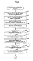
- FIG. 2 is a flowchart of a condition determination process according to the embodiments
- FIG. 3 is a flowchart of a condition determination process according to a first embodiment.
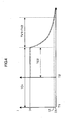
- FIG. 4 is a graph illustrating variations in currents flowing through secondary batteries during the condition determination process.
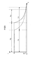
- FIG. 5 is a graph illustrating variations in currents flowing through the secondary batteries during the condition determination process.
- FIG. 6 is a flowchart of a condition determination process according to a second embodiment.
- FIG. 7 is a graph illustrating variations in powers supplied to the second batteries during the condition determination process.
- a charging device 10 illustrated in FIG. 1 is configured to charge a secondary battery 12 (an electric storage device) when the secondary battery 12 is connected thereto.
- the charging device 10 includes a battery management system (BMS) 20 for determining conditions of the secondary battery 12 (a condition determination device), for instance, degradation of the second battery 12.
- An electrically chargeable device 38 includes the secondary battery 12 and the BMS 20.
- the electrically chargeable device 38 is configured to charge the secondary battery 12 and to determine conditions of the secondary battery 12.
- a lithium ion battery is used for the secondary battery 12.
- the charging device 10 includes the BMS 20, a charging circuit 26, and charging wires 28.
- the charging circuit 26 is provided outside the BMS 20.
- the charging circuit 26 is connected to an external power source 14 and configured to feed power from the external power source 14 to the secondary battery 12 via connecting terminals 16 and the charging wires 28.
- the BMS 20 includes a central processing unit (CPU) 30, a memory unit 32, an analog-to-digital converter (ADC) 34, a thermometer 18, an ammeter 22 (a current detector), a voltmeter 24 (a voltage detector), and a bus 36.
- the memory unit 32 includes a ROM and a RAM.
- the bus 36 connects the CPU 30, the memory unit 32, the ADC 34, the thermometer 18, the ammeter 22, and the voltmeter 24.
- the memory unit 32 stores various programs for controlling operations of the charging device 10.
- the CPU 30 includes a timer portion 40, a control portion 42, a determination portion 44, and an acquisition portion 46.
- the CPU 30 controls the operations of the charging device 10 and sends signals to the charging circuit 26.
- the thermometer 18 is a contact-type thermometer or a non-contact-type thermometer configured to measure a temperature of the secondary battery 12. Data on the measured temperature Y is sent to the memory unit 32 via the bus 36 and stored in the memory unit 32.
- the ammeter 22 measures a charging current and a discharging current (hereinafter each may be referred to as a current) flowing through the secondary battery 12 via the charging wires 28 every predetermined period. Data on the measured current I is sent to the ADC 34.
- the voltmeter 24 is connected to ends of the secondary battery 12 and configured to measure a voltage across the ends of the secondary battery 12. Data on the measured voltage V is sent to the ADC 34.
- the voltmeter 24 is configured to directly measure the voltage across the ends of the secondary battery 12 without using the charging wires 28. Namely, a charging voltage and a discharging voltage (hereinafter each may be referred to as a voltage) can be accurately measured without affected by resistances of the charging wires 28.
- the ADC 34 is connected to the ammeter 22 and the voltmeter 24 .
- the ADC 34 converts the analog data on the current I and the voltage V to digital data.
- the analog data is sent from the ammeter 22 and the voltmeter 24, respectively.
- the digital data on the current I and the voltage V are? sent to the memory unit 32 via the bus 36 and stored in the memory unit 32.
- the CPU 30 performs control, determination, and acquisition using the control portion 42, the determination portion 44, and the acquisition portion 46. For the control, the determination, and the acquisition, the CPU 30 uses the current data and the voltage data.
- the charging device 10 further includes an input unit 50 and a display 52.
- a user can input data through the input unit 50.
- the display 52 is a liquid crystal display configured to display conditions of the charging device 10 and determination results.
- FIG. 4 A condition determination process performed by the BMS 20 during the charge of the secondary battery 12 by the charging device 10 will be explained with reference to FIGS. 2 to 4 .
- the secondary battery 12 is charged with constant voltage after being charged with constant current. Measurement of currents is performed on two different secondary batteries 12 in the same deterioration condition but in different charged conditions. Variations in measured currents are illustrated in FIG. 4 .
- a solid line indicates a current flowing through the secondary battery 12 during the charge from a fully discharged condition, which is a reference condition.
- Symbol T1 indicates elapsed time of the charge from the fully discharged condition.
- a chain line indicates a current flowing through the secondary battery 12 during the charge from a 50% charged condition, that is, a state of charge (SOC) is 50%.
- SOC state of charge
- T2 indicates elapsed time of the charge from the 50% charged condition.
- the CPU executes the condition determination process according to the program stored in the memory unit 32.
- the CPU 30 obtains the SOC at the time when the process is started using the acquisition portion 46 (S2).
- the SOC and the voltage V are associated with each other and stored in the memory unit 32.
- the CPU 30 measures the voltage V of the secondary battery 12 at the time when the process is started using the voltmeter 24.
- the CPU 30 obtains the SOC associated with the measured voltage V and set as an initial SOC (an initial value) expressed in percentage (%) at the time when the process is started.
- the SOC data obtained in step S2, which will be explained later, is set as the initial SOC immediately before the constant current charge is started. Namely, the initial SOC corresponds to the SOC at the time when measurement of the constant current charging time TC is started.
- the CPU 30 notifies the charging circuit 26 of the input of the instruction for charging the secondary battery 12 (S4), and the charging circuit 26 starts charging the secondary battery 12 .
- the charging circuit 26 performs a constant current charge to charge the secondary battery 12 with a constant current flowing through the secondary battery 12 equal to a reference current IK.
- the CPU 30 starts measurement of constant current charging time TC during which the secondary battery 12 is charged with the constant current (S6).
- the constant current charging time TC may be referred to as a first charging time.
- the reference current IK is stored in the memory unit 32 in advance.
- the CPU 30 monitors a level of the current (a level of a first electric factor) flowing through the secondary battery 12 with measurements of the ammeter 22. When a current I flowing through the secondary battery 12 reaches the reference current IK, the CPU 30 starts measuring time.
- the CPU 30 measures the temperature Y of the secondary battery 12 using the thermometer 18 (S8).
- the CPU 30 monitors a level of the voltage (a level of a second electric factor) applied to the secondary battery 12 with measurement of the voltmeter 24 using the control portion 42 (if NO in step S10).
- a reference voltage VK is stored in the memory unit 32 in advance.
- the CPU 30 ends the measurement of the constant current charging time TC and stores the measured constant current charging time TC in the memory unit 32(S12).
- the charging circuit 26 When the voltage applied to the secondary battery 12 exceeds the reference voltage VK, the charging circuit 26 performs a constant voltage charge to charge the secondary battery 12 with a constant voltage applied to the secondary battery 12 equal to the reference voltage VK. As illustrated in FIG. 4 , the current flowing through the secondary battery 12 gradually decreases from the reference current IK immediately after the start of the constant voltage charge as the charge progresses.
- the CPU 30 starts measuring constant voltage charging time TV during which the secondary battery 12 is charged with the constant voltage (S14).
- the constant voltage charging time TV may be referred to as a second charging time.
- the CPU 30 starts the measurement of the constant voltage charging time TV since the end of the measurement of the constant current charging time TC using the timer portion 40.
- the CPU 30 monitors the level the current flowing through the secondary battery 12 with the measurements of the ammeter 22 using the control portion 42 (if NO in step S16).
- a termination current IZ is stored in the memory unit 32 in advance.
- the CPU 30 ends the measurement of the constant voltage charging time TV and stores the measured constant voltage charging time TV in the memory unit 32 (S18).
- the charging circuit 26 terminates the charge.
- the charge termination current IX is set lower than the termination current IZ.
- the termination current IZ is set based on assumed noise that may occur in the charging wires 28 of the charging device 10. In this embodiment, the termination current IZ is set higher than a variation in current flowing through the second battery 12 due to the noise in the charging wiring 28. With this configuration, the measurement of the constant voltage charging time TV is less likely to be terminated due to the noise that may irregularly occur.
- the CPU 30 determines the condition of the secondary battery 12 based on the SOC, the measured temperature Y, the measured constant current charging time TC, and the measured constant voltage charging time TV using the determination portion 44.
- the CPU 30 calculates a reference value D and a correction value C (S20).
- the reference value D is calculated by subtracting the SOC in the reference condition from 100%.
- the reference condition is the fully discharged condition. Therefore, the reference value is 100%.
- the correction value C is calculated by subtracting the initial SOC from 100% and diving the reference value D by the result of the subtraction.
- the CPU 30 sets a temperature parameter ⁇ based on the measured temperature Y (S22).
- the temperature parameter ⁇ is set to a small value when the measured temperature Y is high and so as to increase as the measured temperature Y decreases.
- the CPU 30 calculates a correction charge time TH as follows based on the constant current charging time TC, the correction value C, and the temperature parameter ⁇ (S24).
- the correction charge time TH is equal to time calculated by multiplying the constant current charging time TC by the temperature parameter ⁇ . If the initial SOC of the second battery 12 is 50% (see the chain line in FIG. 4 ), the correction charge time TH is equal to time calculated by multiplying the constant current charging time TC2 by 2. As illustrated in FIG. 4 , the constant current charging time TC2 for charging the secondary battery 12 with the SOC of 50% is a half of the constant current charging time TC1 for charging the secondary battery 12 with the SOC of 0%.
- the correction charge time TH is constant regardless of the initial SOC. Namely, the correction charge time TH is equal to time converted from the constant current charging time TC measured during the charge of any secondary battery 12 with any SOC to the constant current charging time TC for charging the secondary battery 12 from the fully discharged condition.
- the memory unit 32 stores a reference determination value JK in advance.
- the CPU 30 compares the calculated determination value J with the reference determination value JK, and determines the condition of the secondary battery 12 (S28). If the determination value J is smaller than the reference determination value JK (YES in step S28), the CPU 30 determines that the secondary battery 12 is in a normal condition (S30) and terminates the process. If the determination value J is equal to or larger than the reference determination value JK, (NO in step S28), the CPU 30 determines that the secondary battery 12 is in an abnormal condition (S32) and notifies the user of the secondary battery 12 being in the abnormal condition through the display 52 (S34). Then, the CPU 30 terminates the process.
- FIG. 5 Variations in current flowing through the secondary battery 12 in a certain deterioration condition and the secondary battery 12 in another deterioration condition measured in the condition determination process are illustrated in FIG. 5 .
- the fully discharged secondary batteries 12 are used in the measurement.
- a solid line indicates a variation in current flowing through the secondary battery 12 with relatively light deterioration.
- a chain line indicates a variation in current flowing through the secondary battery 12 with relatively heavy deterioration.
- the secondary battery 12 requires longer constant voltage charging time TV as the deterioration progresses but shorter constant current charging time TC.
- the determination value J is calculated by dividing the constant voltage charging time TV by the constant current charging time TC. Furthermore, the determination value J is compared with the reference determination value JK. Through this process, an abnormal condition such as deterioration can be accurately determined.
- the condition of the secondary battery 12 is determined based on the measured constant current charging time TC and the measured constant voltage charging time TV.
- This configuration can be applied to any device having a charging time measurement function. Namely, high-speed operation or high-accuracy measurement is not required.
- the condition of the secondary battery 12 can be accurately determined at low cost using a simple algorithm.
- the CPU 30 obtains the initial SOC of the secondary battery 12 and calculates the correction charging time TH based on the constant current charging time TC and the obtained initial SOC.
- the correction charging time TH corresponds to the constant current charging time TC elapsed for charging the secondary battery 12 from the fully discharged condition. With this configuration, the battery condition can be accurately determined regardless of the initial SOC.
- the CPU 30 measures the temperature Y of the secondary battery 12 at the start of the charge for the calculation of the determination value J.
- the CPU 30 calculates the temperature parameter ⁇ based on the measured temperature Y, and then calculates the determination value J based on the temperature parameter ⁇ .
- the constant current charging time TC tends to decrease as the temperature decreases and to increase as the temperature increases.
- the constant voltage charging time TV tends to increase as the temperature decreases and to decrease as the temperature increases. Namely, temperature characteristics are different between the constant current charging time TC and the constant voltage charging time TV.
- a second embodiment will be explained with reference to FIG. 6 .
- a comparative determination value H is used for condition determination of the secondary battery 12 in the charging device 10 of this embodiment.
- the comparative determination value H is calculated by dividing a determination value J calculated in the current condition determination process by a determination value JO calculated in the previous condition determination process.
- Other configurations of the charging device 10 are the same as those of the first embodiment.
- the charging device 10 of this embodiment repeatedly executes the condition determination process for a specific one of the secondary batteries 12.
- the CPU 30 stores the determination values J calculated in the condition determination processes in the memory unit 32.
- the CPU 30 counts the number of times that the condition determination process is executed for the specific secondary battery 12. Then, the CPU 30 associates the number of times with the determination values J and stores the determination values J in the memory unit 32.
- the CPU 30 After the calculation of the determination value J (S26), the CPU 30 associates the number of times of the determination with the determination value J and stores the determination value J with the associated number in the memory unit 32 (S42) .
- the memory 32 stores a reference comparative value HK determined based on an assumed aging condition.
- the CPU 30 compares the calculated comparative determination value H with the reference comparative value HK (S48). If the comparative determination value H is smaller than the reference comparative value HK (YES in step S48), the CPU 30 determines that deterioration heavier than aging has not been caused by any factor such as a breakage in the secondary battery 12 since the previous condition determination process (S50), and terminates the process. If the comparative determination value H is equal to or larger than the reference comparative value HK (NO in step S48), the CPU 30 determines that deterioration heavier than aging has been caused by any other factor in the secondary battery 12 (S52). The CPU 30 notifies the user of the deterioration through the display 52 (S54) and then terminates the process.
- the condition of the secondary battery 12 is determined based on the comparative determination value H calculated by dividing the current determination value J by the previous determination value JO.
- the comparative determination value H is larger than 1, failures may have occurred in the BMS.
- a third embodiment will be explained with reference to FIG. 7 .
- the secondary battery 12 is charged first with a constant voltage and then with a constant current.
- Other configurations are the same as those of the first embodiment.
- the charging circuit 26 sets power supplied to the secondary battery 12 to a constant level equal to a reference power WK, and charges the secondary battery 12 with the constant power.
- the CPU 30 monitors a level of the current flowing through the secondary battery 12 with the measurements of the ammeter 22 and a level of the voltage applied to the secondary battery 12 with the measurements of the voltmeter 24. Namely, the CPU 30 monitors a level of the power (a level of a first electric factor)
- the CPU 30 starts the measurement of the constant power charging time TW using the timer portion 40.
- the CPU 30 measures the constant power charging time TW while the level of the power is constant.
- the constant power charging time TW may be referred to as a first charging time.
- the CPU 30 monitors the level of the voltage applied to the secondary battery 12 with the measurements of the voltmeter 24. When the voltage applied to the secondary battery 12 reaches the reference voltage VK, the CPU 30 ends the measurement of the constant power charging time TW and stores the measured constant power charging time TW in the memory unit 32.
- the charging circuit 26 sets the voltage applied to the secondary battery 12 to the reference voltage VK, and charges the secondary battery 12 with a constant voltage.
- the CPU 30 starts the measurement of the constant voltage charging time using the timer portion 40.
- the CPU 30 measures the constant voltage charging time while the voltage is constant.
- the rest of the process is similar to the corresponding part of the process in the first embodiment using the constant current charging time TC. Namely, the constant current charging time TC is replaced by the constant power charging time TW in the process of this embodiment.
- the CPU 30 calculates the correction charging time TH based on the constant power charging time TW, and then calculates the determination value J based on the correction charging time TH and the constant voltage charging time TV.
- the CPU 30 determines the condition of the secondary battery 12 based on the determination value J.
- Measurement of currents is performed on two different secondary batteries 12 in different deterioration condition in the condition determination process. Variations in measured currents are illustrated in FIG. 7 .
- a solid line indicates a variation in current flowing through the secondary battery 12 with relatively light deterioration.
- a chain line indicates a variation in current flowing through the secondary battery 12 with relatively heavy deterioration.
- the current flowing through the secondary battery 12 and the power supplied to the secondary battery 12 decrease during the constant voltage charge.
- the secondary battery 12 requires longer constant voltage charging time TV as the deterioration progresses but shorter constant power charging time TW.
- the determination value J is calculated based on the constant power charging time TW and the constant voltage charging time TV. Therefore, a variation in the determination value J due to the deterioration of the secondary battery 12 is larger than a variation in the constant power charging time TW or the constant voltage charging time TV due to the deterioration of the secondary battery 12. With this configuration, the condition of the secondary battery 12 can be accurately determined.
- the charging device 10 includes a single BMS 20 and a single CPU 30 in the BMS 20.
- the single CPU 30 includes the timer portion 40, the control portion 42, and the determination portion 44.
- the scope of the present invention is not limited to the charging device 10 having such a configuration.
- the charging device 10 may include a plurality of CPUs or hardware circuits for timer, control, and determination functions, respectively.
- Such hardware circuits may be application specific integrated circuits (ASICs).
- ASICs application specific integrated circuits
- a combination of CPU(s) and ASIC(s) may be used for timer, control, and determination functions.
- the determination value J is calculated by dividing the constant voltage charging time TV by the constant current charging time TC.
- the determination value can be calculated as follows: (i) dividing the constant current charging time TC by the constant voltage charging time TV; (ii) subtracting the constant current charging time TC from the constant voltage charging time TV; (iii) subtracting the constant voltage charging time TV from the constant current charging time TC; (iv) dividing the constant voltage charging time TV by a total charging time TM that is a sum of the constant voltage charging time TV and the constant current charging time TC; and (v) dividing the constant current charging time TC by the total charging time TM.
- the voltage V of the secondary battery 12 before being charged and the SOC is obtained based on the voltage V.
- the SOC can be obtained in a different way.
- the secondary battery 12 may remain connected to the charging device 10 during use and the CPU 30 may continuously measure the current I flowing into or out of the secondary battery 12 using the ammeter 22. In such a case, the SOC can be obtained by multiplying the currents 1.
- the comparative determination value H is calculated by dividing the determination value J by the previous determination value JO for determining the condition of the secondary battery 12.
- the comparative determination value H can be calculated in a different way. For instance, the comparative determination value H can be calculated by diving the previous determination value JO by the determination value J.
- the comparative determination value H may be calculated from the difference between the determination value J and the previous determination value JO.
- the comparative determination value H may be calculated by dividing the difference between the determination value J and the previous determination value JO by the previous determination value JO.
- the comparative determination value H may be calculated by dividing the difference between the determination value J and the previous determination value JO by the determination value J.
- the CPU 30 measures the charging time including the constant current charging time TC and the constant voltage charging time TV using the timer portion 40.
- the CPU 30 starts the measurement of the charging time when the current I monitored with the measurements of the ammeter 22 in the BMS 20 or the voltage V monitored with the measurements of the voltmeter 24 in the BMS 20 satisfy a certain condition.
- the BMS 20 may be connected to an external device such as an electronic control unit (ECU) in a vehicle via an input unit.
- the CPU 30 may measure the charging time using the timer portion 40 according to a signal input from the external device at the start or the end of the constant current charge, the constant voltage charge, or the constant power charge.
- the measurement of the charging time by the CPU may not be required.
- the BMS 20 may be connected to an external device such as an ECU in a vehicle via an input unit.
- the CPU 30 may obtain the charging time according to an input regarding the charging time from the external device.
- the fully discharged condition is set as a reference condition.
- any condition can be set as a reference condition.
- the reference value D may be set according to the SOC in the reference condition.
Landscapes
- Physics & Mathematics (AREA)
- General Physics & Mathematics (AREA)
- Engineering & Computer Science (AREA)
- Power Engineering (AREA)
- Secondary Cells (AREA)
- Charge And Discharge Circuits For Batteries Or The Like (AREA)
- Tests Of Electric Status Of Batteries (AREA)
Abstract
Description
- The present invention relates to a technology for determining conditions of electric storage devices to detect certain conditions such as deterioration.
- Electric storage devices that are rechargeable for repeated use, such as secondary batteries, are known. The electric storage devices are currently used in various fields including electric vehicles and more various fields are expected.
- In such an electric storage device, an internal resistance may increase or a storage capacity may decrease due to deterioration as the number of times that the electric storage device is used increases. When the internal resistance is increased, the electric storage device may not be able to provide expected performance, for instance, required maximum voltage and power may not be achieved. A device including such an electric storage device may malfunction due to a voltage decrease. To resolve such a problem, a technology for determining conditions of a battery to detect certain conditions such as deterioration is known. In this technology, degradation of the battery is detected based on battery charging time during which the battery is charged with a constant current. Another technology for determining conditions of a battery based on a measured battery capacity is also known. According to the technology for determining conditions of the battery based on the battery charging time, continuous measurement of a charging current from a fully discharged condition to a fully charged condition is not required. Therefore, the degradation of the battery can be relatively easily detected.
- As the variety of fields in which the electric storage devices are used increases, expectations for an improvement in accuracy of the condition determination for the electric storage devices increase.
- The present invention has been made in consideration of the above circumstances, and an object thereof is to provide a technology for determining conditions of electric storage devices.
- A condition determination device according to technologies described herein is for determining a condition of an electric storage device. The condition determination device includes a current detector, a voltage detector, and a controller. The current detector is configured to detect a charging current for charging the electric storage device. The voltage detector is configured to detect a charging voltage for charging the electric storage device. The controller is configured to: determine a level of a first electric factor based on at least one of the charging current detected by the current detector and the charging voltage detected by the voltage detector; obtain first charging time while the level of the first electric factor is constant; determine a level of a second electric factor based on the charging voltage detected by the voltage detector; obtain second charging time while the level of the second electric factor is constant; calculate a determination value based on the first charging time and the second charging time; and determine a condition of the electric storage device based on the determination value.
- In this condition determination device, the determination value is calculated for the determination of the electric storage condition based on the first charging time and the second time. For example, the determination value is calculated by subtracting the second charging time from the first charging time. With this configuration, a variation in determination value due to deterioration of the electric storage device is larger than a variation in constant current charging time due to the deterioration of the electric storage device. When the determination value is calculated based on the first charging time and the second charging time, the variation in determination value due to a variation in condition of the electric storage device is clearly recognizable. With such a determination value, a condition of the electric storage device can be accurately determined.
- In the condition determination device, the controller may calculate the determination value by diving one of the first charging time and the second charging time by the other one of the first charging time and the second charging time. When the determination value is calculated in this manner, a variation in determination value due to a variation in condition of the electric storage device is larger than a variation in constant current charging time due to the variation in condition of the electric storage device. With such a determination value, a condition of the electric storage device can be accurately determined.
- In the condition determination device, the controller may be further configured to: obtain an initial value that is a state of charge (SOC) of the electric storage device at a start of measurement of the first charge time; subtract the initial value from 100%; obtain a reference SOC of the electric storage device in a reference condition; calculate a reference value by subtracting the reference OSC from 100%; calculate a correction value by dividing the reference value by a result of the subtraction; calculate a correction charging time by multiplying the first charging time by the correction value; and calculate the determination value based on the correction charging time and the second charging time.
- In the condition determination device, the initial SOC may be obtained and the correction charging time may be calculated based on the first charging time and the reference SOC. With this configuration, the first charging time for charging the electric storage device from a specific condition can be converted to the correction charging time that corresponds to the first charging time for charging the electric storage device from the reference condition. Therefore, a condition of the electric storage device can be accurately determined regardless of the initial SOC.
- The condition determination device may further include a memory unit. In this condition determination device, the controller may perform the calculation of the determination value a plurality of times to obtain determination values in the respective times of the determination. The controller may be further configured to: associate numbers of times of the determination with the respective determination values calculated in the respective times of the determination; store the determination values with the associated numbers in the memory unit; compare the currently calculated determination value with the previously calculated determination value; and determine a condition of the electric storage device based on a result of the comparison.
- Because the condition of the electric storage device is determined based on the result of the comparison between the current determination value and the previous determination value, a variation in the condition of the electric storage device since the previous condition can be accurately detected. Furthermore, with this configuration, a malfunction of the condition determination device can be detected.
- The controller may be configured to calculate the determination value by subtracting one of the first charging time and the second charging time from the other one of the first charging time and the second charging time. The controller may be configured to calculate a total charging time by adding the first charging time and the second charging time, and then calculate the determination value by dividing the first charging time by the total charging time. The controller may be calculate a total charging time by adding the first charging time and the second charging time, and then calculate the determination value by dividing the second charging time by the total charging time.
- The first electric factor may be a current determined based on the charging current detected by the current detector. The first electric factor may be a power determined based on the charging current detected by the current detector and the charging voltage detected by the voltage detector.
- An electrically chargeable device according to technologies described herein includes an electric storage device and the condition determination device described above. With this electrically chargeable device, a condition of the electric storage device can be accurately determined based on the determination valued calculated from the first charging time and the second charging time.
- A method of determining a condition of an electric storage device according to the technologies described herein includes: measuring a charging current and a charging voltage; determining a level of a first electric factor based on at least one of the charging current and the charging voltage; obtaining first charging time while the first electric factor is constant during charging the electric storage device; determining a level of a second electric factor based on the charging voltage; obtaining second charging time while the second electric factor is constant during charging the electric storage device after the measurement of the first charging time; calculating a determination value based on the first charging time and the second charging time; and determining a condition of the electric storage device based on the determination value.
- In this method, the determination value for determining a condition of the electric storage device is calculated based on the first charging time and the second charging time. Therefore, a variation in determination value due to a variation in condition of the electric storage device is larger than a variation in constant current charging time due to a variation in condition of the electric storage device. With this determination value, a condition of the electric storage device can be accurately determined.
- According to the technologies described herein, a condition of the electric storage device can be properly determined.
- Illustrative aspects in accordance with the invention will be described in detail with reference to the following figures.
-
FIG. 1 is a block diagram of a condition determination device according to embodiments. -
FIG. 2 is a flowchart of a condition determination process according to the embodiments -
FIG. 3 is a flowchart of a condition determination process according to a first embodiment. -
FIG. 4 is a graph illustrating variations in currents flowing through secondary batteries during the condition determination process. -
FIG. 5 is a graph illustrating variations in currents flowing through the secondary batteries during the condition determination process. -
FIG. 6 is a flowchart of a condition determination process according to a second embodiment. -
FIG. 7 is a graph illustrating variations in powers supplied to the second batteries during the condition determination process. - An embodiment will be explained with reference to
FIGS. 1 to 5 . - A
charging device 10 illustrated inFIG. 1 is configured to charge a secondary battery 12 (an electric storage device) when thesecondary battery 12 is connected thereto. Thecharging device 10 includes a battery management system (BMS) 20 for determining conditions of the secondary battery 12 (a condition determination device), for instance, degradation of thesecond battery 12. An electricallychargeable device 38 includes thesecondary battery 12 and theBMS 20. The electricallychargeable device 38 is configured to charge thesecondary battery 12 and to determine conditions of thesecondary battery 12. In this embodiment, a lithium ion battery is used for thesecondary battery 12. - As illustrated in
FIG. 1 , the chargingdevice 10 includes theBMS 20, a chargingcircuit 26, and chargingwires 28. The chargingcircuit 26 is provided outside theBMS 20. The chargingcircuit 26 is connected to anexternal power source 14 and configured to feed power from theexternal power source 14 to thesecondary battery 12 via connectingterminals 16 and the chargingwires 28. - The
BMS 20 includes a central processing unit (CPU) 30, amemory unit 32, an analog-to-digital converter (ADC) 34, athermometer 18, an ammeter 22 (a current detector), a voltmeter 24 (a voltage detector), and abus 36. Thememory unit 32 includes a ROM and a RAM. Thebus 36 connects theCPU 30, thememory unit 32, theADC 34, thethermometer 18, theammeter 22, and thevoltmeter 24. - The
memory unit 32 stores various programs for controlling operations of the chargingdevice 10. TheCPU 30 includes atimer portion 40, acontrol portion 42, adetermination portion 44, and anacquisition portion 46. TheCPU 30 controls the operations of the chargingdevice 10 and sends signals to the chargingcircuit 26. - The
thermometer 18 is a contact-type thermometer or a non-contact-type thermometer configured to measure a temperature of thesecondary battery 12. Data on the measured temperature Y is sent to thememory unit 32 via thebus 36 and stored in thememory unit 32. Theammeter 22 measures a charging current and a discharging current (hereinafter each may be referred to as a current) flowing through thesecondary battery 12 via the chargingwires 28 every predetermined period. Data on the measured current I is sent to theADC 34. Thevoltmeter 24 is connected to ends of thesecondary battery 12 and configured to measure a voltage across the ends of thesecondary battery 12. Data on the measured voltage V is sent to theADC 34. Thevoltmeter 24 is configured to directly measure the voltage across the ends of thesecondary battery 12 without using the chargingwires 28. Namely, a charging voltage and a discharging voltage (hereinafter each may be referred to as a voltage) can be accurately measured without affected by resistances of the chargingwires 28. - The
ADC 34 is connected to theammeter 22 and thevoltmeter 24 . TheADC 34 converts the analog data on the current I and the voltage V to digital data. The analog data is sent from theammeter 22 and thevoltmeter 24, respectively. The digital data on the current I and the voltage V are? sent to thememory unit 32 via thebus 36 and stored in thememory unit 32. TheCPU 30 performs control, determination, and acquisition using thecontrol portion 42, thedetermination portion 44, and theacquisition portion 46. For the control, the determination, and the acquisition, theCPU 30 uses the current data and the voltage data. - The charging
device 10 further includes aninput unit 50 and adisplay 52. A user can input data through theinput unit 50. Thedisplay 52 is a liquid crystal display configured to display conditions of the chargingdevice 10 and determination results. - A condition determination process performed by the
BMS 20 during the charge of thesecondary battery 12 by the chargingdevice 10 will be explained with reference toFIGS. 2 to 4 . In this embodiment, thesecondary battery 12 is charged with constant voltage after being charged with constant current. Measurement of currents is performed on two differentsecondary batteries 12 in the same deterioration condition but in different charged conditions. Variations in measured currents are illustrated inFIG. 4 . InFIG. 4 , a solid line indicates a current flowing through thesecondary battery 12 during the charge from a fully discharged condition, which is a reference condition. Symbol T1 indicates elapsed time of the charge from the fully discharged condition. A chain line indicates a current flowing through thesecondary battery 12 during the charge from a 50% charged condition, that is, a state of charge (SOC) is 50%. Symbol T2 indicates elapsed time of the charge from the 50% charged condition. - When an instruction for charging the
secondary battery 12 is input by the user through theinput unit 50, the CPU executes the condition determination process according to the program stored in thememory unit 32. After the process is started, theCPU 30 obtains the SOC at the time when the process is started using the acquisition portion 46 (S2). The SOC and the voltage V are associated with each other and stored in thememory unit 32. TheCPU 30 measures the voltage V of thesecondary battery 12 at the time when the process is started using thevoltmeter 24. TheCPU 30 obtains the SOC associated with the measured voltage V and set as an initial SOC (an initial value) expressed in percentage (%) at the time when the process is started. The SOC data obtained in step S2, which will be explained later, is set as the initial SOC immediately before the constant current charge is started. Namely, the initial SOC corresponds to the SOC at the time when measurement of the constant current charging time TC is started. - The
CPU 30 notifies the chargingcircuit 26 of the input of the instruction for charging the secondary battery 12 (S4), and the chargingcircuit 26 starts charging thesecondary battery 12 . The chargingcircuit 26 performs a constant current charge to charge thesecondary battery 12 with a constant current flowing through thesecondary battery 12 equal to a reference current IK. TheCPU 30 starts measurement of constant current charging time TC during which thesecondary battery 12 is charged with the constant current (S6). The constant current charging time TC may be referred to as a first charging time. The reference current IK is stored in thememory unit 32 in advance. TheCPU 30 monitors a level of the current (a level of a first electric factor) flowing through thesecondary battery 12 with measurements of theammeter 22. When a current I flowing through thesecondary battery 12 reaches the reference current IK, theCPU 30 starts measuring time. TheCPU 30 measures the temperature Y of thesecondary battery 12 using the thermometer 18 (S8). - During the constant current charge of the
secondary battery 12, theCPU 30 monitors a level of the voltage (a level of a second electric factor) applied to thesecondary battery 12 with measurement of thevoltmeter 24 using the control portion 42 (if NO in step S10). A reference voltage VK is stored in thememory unit 32 in advance. When the voltage applied to thesecondary battery 12 reaches the reference voltage VK (YES in step S10), theCPU 30 ends the measurement of the constant current charging time TC and stores the measured constant current charging time TC in the memory unit 32(S12). - When the voltage applied to the
secondary battery 12 exceeds the reference voltage VK, the chargingcircuit 26 performs a constant voltage charge to charge thesecondary battery 12 with a constant voltage applied to thesecondary battery 12 equal to the reference voltage VK. As illustrated inFIG. 4 , the current flowing through thesecondary battery 12 gradually decreases from the reference current IK immediately after the start of the constant voltage charge as the charge progresses. TheCPU 30 starts measuring constant voltage charging time TV during which thesecondary battery 12 is charged with the constant voltage (S14). The constant voltage charging time TV may be referred to as a second charging time. TheCPU 30 starts the measurement of the constant voltage charging time TV since the end of the measurement of the constant current charging time TC using thetimer portion 40. - During the constant voltage charge of the
secondary battery 12, theCPU 30 monitors the level the current flowing through thesecondary battery 12 with the measurements of theammeter 22 using the control portion 42 (if NO in step S16). A termination current IZ is stored in thememory unit 32 in advance. When the current flowing through thesecondary battery 12 drops below the termination current IZ (YES in step S16), theCPU 30 ends the measurement of the constant voltage charging time TV and stores the measured constant voltage charging time TV in the memory unit 32 (S18). When the current flowing through thesecondary battery 12 becomes equal to a charge termination current IX, the chargingcircuit 26 terminates the charge. The charge termination current IX is set lower than the termination current IZ. - The termination current IZ is set based on assumed noise that may occur in the charging
wires 28 of the chargingdevice 10. In this embodiment, the termination current IZ is set higher than a variation in current flowing through thesecond battery 12 due to the noise in the chargingwiring 28. With this configuration, the measurement of the constant voltage charging time TV is less likely to be terminated due to the noise that may irregularly occur. - The
CPU 30 determines the condition of thesecondary battery 12 based on the SOC, the measured temperature Y, the measured constant current charging time TC, and the measured constant voltage charging time TV using thedetermination portion 44. - The
CPU 30 calculates a reference value D and a correction value C (S20). The reference value D is calculated by subtracting the SOC in the reference condition from 100%. In this embodiment, the reference condition is the fully discharged condition. Therefore, the reference value is 100%. The correction value C is calculated by subtracting the initial SOC from 100% and diving the reference value D by the result of the subtraction. TheCPU 30 sets a temperature parameter α based on the measured temperature Y (S22). The temperature parameter α is set to a small value when the measured temperature Y is high and so as to increase as the measured temperature Y decreases. TheCPU 30 calculates a correction charge time TH as follows based on the constant current charging time TC, the correction value C, and the temperature parameter α (S24).

- If the
secondary battery 12 is in the fully discharged condition, that is, the initial SOC of thesecondary battery 12 is 0% (see the solid line inFIG. 4 ), the correction charge time TH is equal to time calculated by multiplying the constant current charging time TC by the temperature parameter α. If the initial SOC of thesecond battery 12 is 50% (see the chain line inFIG. 4 ), the correction charge time TH is equal to time calculated by multiplying the constant current charging time TC2 by 2. As illustrated inFIG. 4 , the constant current charging time TC2 for charging thesecondary battery 12 with the SOC of 50% is a half of the constant current charging time TC1 for charging thesecondary battery 12 with the SOC of 0%. The correction charge time TH is constant regardless of the initial SOC. Namely, the correction charge time TH is equal to time converted from the constant current charging time TC measured during the charge of anysecondary battery 12 with any SOC to the constant current charging time TC for charging thesecondary battery 12 from the fully discharged condition. - The
CPU 30 calculates a determination value J by dividing the constant voltage charging time TV by the correction charge time TH (S26). If thesecondary battery 12 is in the fully discharged condition, the determination value J is calculated by dividing the constant voltage charging time TV by the temperature parameter α and the constant current charging time TC. As illustrated inFIG. 4 , the constant voltage charging time TV1 (or TV2) is constant regardless of the initial SOC. As described earlier, the correction charge time TH is constant regardless of the initial SOC. Therefore, the determination value J calculated based on the constant voltage charging time TV and the correction charge time TH is also constant.
- The
memory unit 32 stores a reference determination value JK in advance. TheCPU 30 compares the calculated determination value J with the reference determination value JK, and determines the condition of the secondary battery 12 (S28). If the determination value J is smaller than the reference determination value JK (YES in step S28), theCPU 30 determines that thesecondary battery 12 is in a normal condition (S30) and terminates the process. If the determination value J is equal to or larger than the reference determination value JK, (NO in step S28), theCPU 30 determines that thesecondary battery 12 is in an abnormal condition (S32) and notifies the user of thesecondary battery 12 being in the abnormal condition through the display 52 (S34). Then, theCPU 30 terminates the process. - Variations in current flowing through the
secondary battery 12 in a certain deterioration condition and thesecondary battery 12 in another deterioration condition measured in the condition determination process are illustrated inFIG. 5 . The fully dischargedsecondary batteries 12 are used in the measurement. InFIG. 5 , a solid line indicates a variation in current flowing through thesecondary battery 12 with relatively light deterioration. A chain line indicates a variation in current flowing through thesecondary battery 12 with relatively heavy deterioration. - As illustrated in
FIG. 5 , thesecondary battery 12 requires longer constant voltage charging time TV as the deterioration progresses but shorter constant current charging time TC. In the condition determination process, the determination value J is calculated by dividing the constant voltage charging time TV by the constant current charging time TC. Furthermore, the determination value J is compared with the reference determination value JK. Through this process, an abnormal condition such as deterioration can be accurately determined. -
- (1) In the charging
device 10, the determination value J is calculated based on the constant current charging time TC and the constant voltage charging time TV. Specifically, the determination value J is calculated by dividing the constant voltage charging time TV by the constant current charging time TC. Therefore, a variation in the determination value J due to the deterioration of thesecondary battery 12 is larger than a variation in the constant current charging time TC due to the deterioration of thesecondary battery 12. With this configuration, the battery condition can be accurately determined. - (2) In the charging
device 10, the condition of thesecondary battery 12 is determined based on the measured constant current charging time TC and the measured constant voltage charging time TV. This configuration can be applied to any device having a charging time measurement function. Namely, high-speed operation or high-accuracy measurement is not required. According to the chargingdevice 10, the condition of thesecondary battery 12 can be accurately determined at low cost using a simple algorithm. - (3) The
CPU 30 obtains the initial SOC of thesecondary battery 12 and calculates the correction charging time TH based on the constant current charging time TC and the obtained initial SOC. The correction charging time TH corresponds to the constant current charging time TC elapsed for charging thesecondary battery 12 from the fully discharged condition. With this configuration, the battery condition can be accurately determined regardless of the initial SOC. - (4) In the charging
device 10, theCPU 30 measures the temperature Y of thesecondary battery 12 at the start of the charge for the calculation of the determination valueJ. The CPU 30 calculates the temperature parameter α based on the measured temperature Y, and then calculates the determination value J based on the temperature parameter α. The constant current charging time TC tends to decrease as the temperature decreases and to increase as the temperature increases. The constant voltage charging time TV tends to increase as the temperature decreases and to decrease as the temperature increases. Namely, temperature characteristics are different between the constant current charging time TC and the constant voltage charging time TV. By calculating the determination value J based on the temperature parameter α, the difference between the constant current charging time TC and the constant voltage charging time TV caused by the different temperature characteristics thereof can be compensated. Therefore, the condition of thesecondary battery 12 can be accurately determined regardless of the temperature of thesecondary battery 12. - A second embodiment will be explained with reference to
FIG. 6 . As illustrated inFIG. 6 , a comparative determination value H is used for condition determination of thesecondary battery 12 in the chargingdevice 10 of this embodiment. The comparative determination value H is calculated by dividing a determination value J calculated in the current condition determination process by a determination value JO calculated in the previous condition determination process. Other configurations of the chargingdevice 10 are the same as those of the first embodiment. - In the charging
device 10 of this embodiment repeatedly executes the condition determination process for a specific one of thesecondary batteries 12. TheCPU 30 stores the determination values J calculated in the condition determination processes in thememory unit 32. TheCPU 30 counts the number of times that the condition determination process is executed for the specificsecondary battery 12. Then, theCPU 30 associates the number of times with the determination values J and stores the determination values J in thememory unit 32. In the following description, configurations, functions, and effects that are the same as the first embodiment will not be explained. - After the calculation of the determination value J (S26), the
CPU 30 associates the number of times of the determination with the determination value J and stores the determination value J with the associated number in the memory unit 32 (S42) . TheCPU 30 reads the previous determination value JO with the associated number indicating the previous time of the determination out of the memory unit 32 (S44). Then, theCPU 30 calculates the comparative determination value H by dividing the determination value J by the previous determination value JO (S46).
- The
memory 32 stores a reference comparative value HK determined based on an assumed aging condition. TheCPU 30 compares the calculated comparative determination value H with the reference comparative value HK (S48). If the comparative determination value H is smaller than the reference comparative value HK (YES in step S48), theCPU 30 determines that deterioration heavier than aging has not been caused by any factor such as a breakage in thesecondary battery 12 since the previous condition determination process (S50), and terminates the process. If the comparative determination value H is equal to or larger than the reference comparative value HK (NO in step S48), theCPU 30 determines that deterioration heavier than aging has been caused by any other factor in the secondary battery 12 (S52). TheCPU 30 notifies the user of the deterioration through the display 52 (S54) and then terminates the process. - In the charging
device 10 of this embodiment, the condition of thesecondary battery 12 is determined based on the comparative determination value H calculated by dividing the current determination value J by the previous determination value JO. With this configuration, a variation in battery condition since the previous condition determination can be accurately determined. If the current determination value J is larger than the previous determination value JO, that is, the comparative determination value H is larger than 1, failures may have occurred in the BMS. By using the comparative determination value H for the determination of the condition of thesecondary battery 12, a malfunction of the BMS can be detected. - A third embodiment will be explained with reference to
FIG. 7 . In the chargingdevice 10 of this embodiment, thesecondary battery 12 is charged first with a constant voltage and then with a constant current. Other configurations are the same as those of the first embodiment. - When the charge of the
secondary battery 12 is started, the chargingcircuit 26 sets power supplied to thesecondary battery 12 to a constant level equal to a reference power WK, and charges thesecondary battery 12 with the constant power. TheCPU 30 monitors a level of the current flowing through thesecondary battery 12 with the measurements of theammeter 22 and a level of the voltage applied to thesecondary battery 12 with the measurements of thevoltmeter 24. Namely, theCPU 30 monitors a level of the power (a level of a first electric factor) TheCPU 30 starts the measurement of the constant power charging time TW using thetimer portion 40. TheCPU 30 measures the constant power charging time TW while the level of the power is constant. The constant power charging time TW may be referred to as a first charging time. - During the constant power charge of the
secondary battery 12, theCPU 30 monitors the level of the voltage applied to thesecondary battery 12 with the measurements of thevoltmeter 24. When the voltage applied to thesecondary battery 12 reaches the reference voltage VK, theCPU 30 ends the measurement of the constant power charging time TW and stores the measured constant power charging time TW in thememory unit 32. - When the voltage applied to the
secondary battery 12 exceeds the reference voltage VK, the chargingcircuit 26 sets the voltage applied to thesecondary battery 12 to the reference voltage VK, and charges thesecondary battery 12 with a constant voltage. TheCPU 30 starts the measurement of the constant voltage charging time using thetimer portion 40. TheCPU 30 measures the constant voltage charging time while the voltage is constant. The rest of the process is similar to the corresponding part of the process in the first embodiment using the constant current charging time TC. Namely, the constant current charging time TC is replaced by the constant power charging time TW in the process of this embodiment. Specifically, theCPU 30 calculates the correction charging time TH based on the constant power charging time TW, and then calculates the determination value J based on the correction charging time TH and the constant voltage charging time TV. TheCPU 30 determines the condition of thesecondary battery 12 based on the determination value J. - Measurement of currents is performed on two different
secondary batteries 12 in different deterioration condition in the condition determination process. Variations in measured currents are illustrated inFIG. 7 . InFIG. 7 , a solid line indicates a variation in current flowing through thesecondary battery 12 with relatively light deterioration. A chain line indicates a variation in current flowing through thesecondary battery 12 with relatively heavy deterioration. - As illustrated in
FIG. 7 , the current flowing through thesecondary battery 12 and the power supplied to thesecondary battery 12 decrease during the constant voltage charge. Thesecondary battery 12 requires longer constant voltage charging time TV as the deterioration progresses but shorter constant power charging time TW. - In the charging
device 10, the determination value J is calculated based on the constant power charging time TW and the constant voltage charging time TV. Therefore, a variation in the determination value J due to the deterioration of thesecondary battery 12 is larger than a variation in the constant power charging time TW or the constant voltage charging time TV due to the deterioration of thesecondary battery 12. With this configuration, the condition of thesecondary battery 12 can be accurately determined. - The scope of the present invention is not limited to the above embodiments. The following embodiments are also included in the scope of the present invention.
- (1) The charging
device 10 includes asingle BMS 20 and asingle CPU 30 in theBMS 20. Thesingle CPU 30 includes thetimer portion 40, thecontrol portion 42, and thedetermination portion 44. However, the scope of the present invention is not limited to the chargingdevice 10 having such a configuration. For instance, the chargingdevice 10 may include a plurality of CPUs or hardware circuits for timer, control, and determination functions, respectively. Such hardware circuits may be application specific integrated circuits (ASICs). Furthermore, a combination of CPU(s) and ASIC(s) may be used for timer, control, and determination functions. - (2) In the above embodiments, the determination value J is calculated by dividing the constant voltage charging time TV by the constant current charging time TC. However, a determination value calculated in a different way can be used. For instance, the determination value can be calculated as follows: (i) dividing the constant current charging time TC by the constant voltage charging time TV; (ii) subtracting the constant current charging time TC from the constant voltage charging time TV; (iii) subtracting the constant voltage charging time TV from the constant current charging time TC; (iv) dividing the constant voltage charging time TV by a total charging time TM that is a sum of the constant voltage charging time TV and the constant current charging time TC; and (v) dividing the constant current charging time TC by the total charging time TM.


- (3) In the above embodiments, the voltage V of the
secondary battery 12 before being charged and the SOC is obtained based on the voltage V. However, the SOC can be obtained in a different way. For instance, thesecondary battery 12 may remain connected to the chargingdevice 10 during use and theCPU 30 may continuously measure the current I flowing into or out of thesecondary battery 12 using theammeter 22. In such a case, the SOC can be obtained by multiplying thecurrents 1. - (4) In the above embodiments, the comparative determination value H is calculated by dividing the determination value J by the previous determination value JO for determining the condition of the
secondary battery 12. However, the comparative determination value H can be calculated in a different way. For instance, the comparative determination value H can be calculated by diving the previous determination value JO by the determination value J. The comparative determination value H may be calculated from the difference between the determination value J and the previous determination value JO. The comparative determination value H may be calculated by dividing the difference between the determination value J and the previous determination value JO by the previous determination value JO. The comparative determination value H may be calculated by dividing the difference between the determination value J and the previous determination value JO by the determination value J. - (5) In the above embodiments, the
CPU 30 measures the charging time including the constant current charging time TC and the constant voltage charging time TV using thetimer portion 40. TheCPU 30 starts the measurement of the charging time when the current I monitored with the measurements of theammeter 22 in theBMS 20 or the voltage V monitored with the measurements of thevoltmeter 24 in theBMS 20 satisfy a certain condition. TheBMS 20 may be connected to an external device such as an electronic control unit (ECU) in a vehicle via an input unit. TheCPU 30 may measure the charging time using thetimer portion 40 according to a signal input from the external device at the start or the end of the constant current charge, the constant voltage charge, or the constant power charge. - (6) The measurement of the charging time by the CPU may not be required. For instance, the
BMS 20 may be connected to an external device such as an ECU in a vehicle via an input unit. TheCPU 30 may obtain the charging time according to an input regarding the charging time from the external device. - (7) In the above embodiments, the fully discharged condition is set as a reference condition. However, any condition can be set as a reference condition. In such a case, the reference value D may be set according to the SOC in the reference condition.
Claims (11)
- A condition determination device for determining a condition of an electric storage device, the condition determination device comprising:a current detector configured to detect a charging current for charging the electric storage device;a voltage detector configured to detect a charging voltage for charging the electric storage device; anda controller configured to:determine a level of a first electric factor based on at least one of the charging current detected by the current detector and the charging voltage detected by the voltage detector;obtain first charging time while the level of the first electric factor is constant;determine a level of a second electric factor based on the charging voltage detected by the voltage detector;obtain second charging time while the level of the second electric factor is constant;calculate a determination value based on the first charging time and the second charging time; anddetermine a condition of the electric storage device based on the determination value.
- The condition determination device according to claim 1, wherein the controller calculates the determination value by diving one of the first charging time and the second charging time by the other one of the first charging time and the second charging time.
- The condition determination device according to claim 1 or 2, wherein the controller further configured to:obtain an initial value that is a state of charge (SOC) of the electric storage device at a start of measurement of the first charging time;subtract the initial value from 100%;obtain a reference SOC of the electric storage device in a reference condition;calculate a reference value by subtracting the reference SOC from 100%;calculate a correction value by dividing the reference value by a result of the subtraction;calculate a correction charging time by multiplying the first charging time by the correction value; andcalculate the determination value based on the correction charging time and the second charging time.
- The condition determination device according to any one of claims 1 to 3, further comprising a memory unit, wherein the controller performs the calculation of the determination value a plurality of times to obtain determination values in the respective times of the determination, the controller being configured to:associate numbers of times of the determination with the respective determination values calculated in the respective times of the determination;store the determination values with the associated numbers in the memory unit;compare the currently calculated determination value with the previously calculated determination value; anddetermine a condition of the electric storage device based on a result of the comparison.
- The condition determination device according to claim 1, wherein the controller is further configured to calculate the determination value by subtracting one of the first charging time and the second charging time from the other one of the first charging time and the second charging time.
- The condition determination device according to claim 1, wherein the controller is further configured to:calculate a total charging time by adding the first charging time and the second charging time; andcalculate the determination value by dividing the first charging time by the total charging time.
- The condition determination device according to claim 1, wherein the controller is further configured to:calculate a total charging time by adding the first charging time and the second charging time; andcalculate the determination value by dividing the second charging time by the total charging time.
- The condition determination device according to claim 1, wherein the first electric factor is a current determined based on the charging current detected by the current detector.
- The condition determination device according to claim 1, wherein the first electric factor is a power determined based on the charging current detected by the current detector and the charging voltage detected by the voltage detector.
- An electrically chargeable device comprising:an electric storage device; andthe condition determination device according to any one of claims 1 to 9.
- A method of determining a condition of an electric storage device, the method comprising:measuring a charging current and a charging voltage;determining a level of a first electric factor based on at least one of the charging current and the charging voltage;obtaining first charging time while the first electric factor is constant during charging the electric storage device;determining a level of a second electric factor based on the charging voltage;obtaining second charging time while the second electric factor is constant during charging the electric storage device after the measurement of the first charging time;calculating a determination value based on the first charging time and the second charging time; anddetermining a condition of the electric storage device based on the determination value.
Applications Claiming Priority (2)
| Application Number | Priority Date | Filing Date | Title |
|---|---|---|---|
| JP2011125604 | 2011-06-03 | ||
| JP2012111279A JP6044114B2 (en) | 2011-06-03 | 2012-05-15 | State determination device, power storage device, and state determination method |
Publications (4)
| Publication Number | Publication Date |
|---|---|
| EP2530478A2 true EP2530478A2 (en) | 2012-12-05 |
| EP2530478A3 EP2530478A3 (en) | 2013-04-03 |
| EP2530478A8 EP2530478A8 (en) | 2013-07-03 |
| EP2530478B1 EP2530478B1 (en) | 2017-11-01 |
Family
ID=46750139
Family Applications (1)
| Application Number | Title | Priority Date | Filing Date |
|---|---|---|---|
| EP12004196.7A Active EP2530478B1 (en) | 2011-06-03 | 2012-05-31 | Electric storage device condition determination device and corresponding method |
Country Status (5)
| Country | Link |
|---|---|
| US (1) | US9018897B2 (en) |
| EP (1) | EP2530478B1 (en) |
| JP (1) | JP6044114B2 (en) |
| KR (1) | KR101895619B1 (en) |
| CN (1) | CN102809730A (en) |
Cited By (4)
| Publication number | Priority date | Publication date | Assignee | Title |
|---|---|---|---|---|
| FR3011393A1 (en) * | 2013-10-01 | 2015-04-03 | Centre Nat Rech Scient | METHOD AND APPARATUS FOR EVALUATING THE HEALTH CONDITION OF A LITHIUM BATTERY |
| EP2889633A3 (en) * | 2013-12-05 | 2015-10-21 | Hyundai Motor Company | Battery deterioration determining apparatus for electric vehicle and method thereof |
| FR3060132A1 (en) * | 2016-12-14 | 2018-06-15 | Commissariat A L'energie Atomique Et Aux Energies Alternatives | METHOD FOR DETERMINING THE HEALTH STATUS OF A NICKEL SODIUM CHLORIDE BATTERY |
| IT201900021297A1 (en) * | 2019-11-15 | 2021-05-15 | Futura Batterie Srl | METHOD OF CHARGING AN ACCUMULATOR |
Families Citing this family (18)
| Publication number | Priority date | Publication date | Assignee | Title |
|---|---|---|---|---|
| JP6097599B2 (en) * | 2013-03-07 | 2017-03-15 | 古河電気工業株式会社 | Secondary battery state detection method and state detection device |
| JP2014217115A (en) * | 2013-04-23 | 2014-11-17 | パナソニックインテレクチュアル プロパティ コーポレーション オブアメリカPanasonic Intellectual Property Corporation of America | Electronic apparatus and battery charger |
| CN104459547B (en) * | 2013-09-25 | 2018-02-23 | 深圳市瑞能实业股份有限公司 | A kind of battery detection equipment and its detection method |
| WO2015063860A1 (en) * | 2013-10-29 | 2015-05-07 | 三菱電機株式会社 | Discharge circuit malfunction diagnosis device and malfunction diagnosis method |
| CN103777147B (en) * | 2014-01-23 | 2016-01-06 | 深圳警翼数码科技有限公司 | Method and the device of law-enforcing recorder charge capacity is detected in a kind of acquisition workstation |
| JP6264147B2 (en) * | 2014-03-28 | 2018-01-24 | 株式会社Gsユアサ | Storage device operating state estimation device, operating state estimation method, and storage system |
| KR102318789B1 (en) * | 2014-09-02 | 2021-10-28 | 삼성전자 주식회사 | Method for managing bettery charging and electlronic device implementing the same |
| EA202090951A1 (en) * | 2017-10-18 | 2020-08-14 | Джапан Тобакко Инк. | BATTERY UNIT, FRAGRANCE INHALATION DEVICE, BATTERY UNIT CONTROL AND PROGRAM |
| KR101841237B1 (en) | 2017-12-06 | 2018-03-22 | 대영채비(주) | State of Charge Monitoring Method for Battery of Electric Automobile |
| US10630084B2 (en) * | 2017-12-21 | 2020-04-21 | International Business Machines Corporation | Battery management system for extending service life of a battery |
| JP7000847B2 (en) * | 2017-12-25 | 2022-01-19 | トヨタ自動車株式会社 | Inspection method and manufacturing method of power storage device |
| JP7056449B2 (en) * | 2018-08-01 | 2022-04-19 | トヨタ自動車株式会社 | Inspection device for power storage device |
| CN110911770B (en) * | 2019-11-26 | 2023-06-27 | Oppo广东移动通信有限公司 | Charging method and equipment to be charged |
| JP7317777B2 (en) * | 2020-09-08 | 2023-07-31 | 株式会社東芝 | Management method, management device and management system |
| KR102578349B1 (en) * | 2020-10-16 | 2023-09-14 | 에코브 주식회사 | Apparatus for managing security of battery charging station for vehicle and method thereof |
| US20240010090A1 (en) * | 2020-10-29 | 2024-01-11 | Tvs Motor Company Limited | A system and method of fast charging a battery using combined constant current and constant voltage charging |
| JP7136175B2 (en) * | 2020-12-22 | 2022-09-13 | カシオ計算機株式会社 | Data processing device, electronic equipment, data processing method and program |
| KR102715583B1 (en) | 2022-11-01 | 2024-10-11 | 주식회사 엘지에너지솔루션 | Apparatus and method for diagnosing battery |
Family Cites Families (17)
| Publication number | Priority date | Publication date | Assignee | Title |
|---|---|---|---|---|
| JP2780700B2 (en) * | 1996-04-15 | 1998-07-30 | 日本電気株式会社 | Rechargeable battery charger |
| JPH11329512A (en) | 1998-05-20 | 1999-11-30 | Fuji Photo Film Co Ltd | Method and apparatus for determining deterioration in capacity of secondary battery |
| US6172481B1 (en) * | 1999-09-02 | 2001-01-09 | Qualcomm Incorporated | Method and apparatus for rapid charging batteries under sub-optimal interconnect conditions |
| JP3547686B2 (en) | 2000-04-03 | 2004-07-28 | 日本電信電話株式会社 | Lithium ion battery capacity estimation method, deterioration determination method, deterioration determination device, and lithium ion battery pack |
| JP3470098B2 (en) | 2000-11-28 | 2003-11-25 | 日本電信電話株式会社 | Lithium ion battery capacity estimation method, deterioration judgment method, deterioration judgment device, and lithium ion battery pack having deterioration judgment function |
| KR100414979B1 (en) * | 2000-03-13 | 2004-01-14 | 니폰 덴신 덴와 가부시끼가이샤 | Capacity estimation method, degradation estimation method and degradation estimation apparatus for lithium-ion cells, and lithium-ion batteries |
| JP3370047B2 (en) | 2000-04-03 | 2003-01-27 | 日本電信電話株式会社 | Lithium ion battery capacity estimation method, deterioration determination method, deterioration determination device, and lithium ion battery pack |
| ATE489757T1 (en) * | 2001-05-29 | 2010-12-15 | Canon Kk | METHOD, DEVICE AND PROGRAM FOR COLLECTING INTERNAL INFORMATION OF A RECHARGEABLE BATTERY AND DEVICE CONTAINING THIS DETECTION DEVICE |
| KR100406796B1 (en) * | 2001-10-17 | 2003-11-21 | 삼성에스디아이 주식회사 | Method to precisely estimate effective full-discharge capacity of secondary battery |
| US6639386B2 (en) * | 2001-11-02 | 2003-10-28 | Sanyo Electric Co., Ltd. | Rechargeable battery device equipped with life determination function |
| JP4050914B2 (en) * | 2002-02-19 | 2008-02-20 | 株式会社日本自動車部品総合研究所 | Secondary battery deterioration judgment method |
| US7190171B2 (en) * | 2002-10-11 | 2007-03-13 | Canon Kabushiki Kaisha | Detecting method and detecting apparatus for detecting internal of rechargeable battery, rechargeable battery pack having said detecting apparatus therein, apparatus having said detecting apparatus therein, program in which said detecting method is incorporated, and medium in which said program is stored |
| JP2007078506A (en) * | 2005-09-14 | 2007-03-29 | Matsushita Electric Ind Co Ltd | Secondary battery life assessment device |
| JP4615453B2 (en) * | 2006-02-01 | 2011-01-19 | 株式会社Nttファシリティーズ | Secondary battery capacity estimation system, program, and secondary battery capacity estimation method |
| JP2008193797A (en) * | 2007-02-05 | 2008-08-21 | Hitachi Koki Co Ltd | Charging device |
| JP2010252474A (en) * | 2009-04-14 | 2010-11-04 | Nissan Motor Co Ltd | Rechargeable battery charging method |
| CN102939682A (en) * | 2009-11-06 | 2013-02-20 | 松下电器产业株式会社 | Battery power supply device and battery power supply system |
-
2012
- 2012-05-15 JP JP2012111279A patent/JP6044114B2/en active Active
- 2012-05-25 CN CN2012101671841A patent/CN102809730A/en active Pending
- 2012-05-31 US US13/485,058 patent/US9018897B2/en active Active
- 2012-05-31 EP EP12004196.7A patent/EP2530478B1/en active Active
- 2012-05-31 KR KR1020120058352A patent/KR101895619B1/en active Active
Non-Patent Citations (1)
| Title |
|---|
| None |
Cited By (7)
| Publication number | Priority date | Publication date | Assignee | Title |
|---|---|---|---|---|
| FR3011393A1 (en) * | 2013-10-01 | 2015-04-03 | Centre Nat Rech Scient | METHOD AND APPARATUS FOR EVALUATING THE HEALTH CONDITION OF A LITHIUM BATTERY |
| WO2015049300A1 (en) * | 2013-10-01 | 2015-04-09 | Centre National De La Recherche Scientifique | Method and apparatus for evaluating the state of health of a lithium battery |
| US10036781B2 (en) | 2013-10-01 | 2018-07-31 | Centre National De La Recherche Scientifique | Method and apparatus for evaluating the state of health of a lithium battery |
| EP2889633A3 (en) * | 2013-12-05 | 2015-10-21 | Hyundai Motor Company | Battery deterioration determining apparatus for electric vehicle and method thereof |
| FR3060132A1 (en) * | 2016-12-14 | 2018-06-15 | Commissariat A L'energie Atomique Et Aux Energies Alternatives | METHOD FOR DETERMINING THE HEALTH STATUS OF A NICKEL SODIUM CHLORIDE BATTERY |
| IT201900021297A1 (en) * | 2019-11-15 | 2021-05-15 | Futura Batterie Srl | METHOD OF CHARGING AN ACCUMULATOR |
| EP3826136A1 (en) * | 2019-11-15 | 2021-05-26 | Futura Batterie S.r.l. | Method of charging a storage battery |
Also Published As
| Publication number | Publication date |
|---|---|
| EP2530478A3 (en) | 2013-04-03 |
| EP2530478B1 (en) | 2017-11-01 |
| JP2013011590A (en) | 2013-01-17 |
| US9018897B2 (en) | 2015-04-28 |
| KR101895619B1 (en) | 2018-09-05 |
| JP6044114B2 (en) | 2016-12-14 |
| CN102809730A (en) | 2012-12-05 |
| KR20120135075A (en) | 2012-12-12 |
| US20120306436A1 (en) | 2012-12-06 |
| EP2530478A8 (en) | 2013-07-03 |
Similar Documents
| Publication | Publication Date | Title |
|---|---|---|
| EP2530478B1 (en) | Electric storage device condition determination device and corresponding method | |
| EP3279679B1 (en) | Battery control device and electric vehicle system | |
| EP3171187B1 (en) | Battery state detection device, secondary battery system, program product, and battery state detection method | |
| EP2551686B1 (en) | Charge state estimation apparatus | |
| JP6119402B2 (en) | Internal resistance estimation device and internal resistance estimation method | |
| US10393820B2 (en) | Secondary battery state detecting device and secondary battery state detecting method | |
| EP2827164B1 (en) | Battery residual capacitance calculation device and battery residual capacitance calculation method | |
| EP3130934B1 (en) | Battery monitoring device | |
| EP3171186B1 (en) | Battery state detection device, secondary battery system, program product, and battery state detection method | |
| CN104471414B (en) | Battery control device | |
| JP6379956B2 (en) | Storage element abnormality determination device | |
| JP5641215B2 (en) | Secondary battery control device | |
| US10444296B2 (en) | Control device, control method, and recording medium | |
| EP3168954B1 (en) | Battery control device | |
| JP2010019595A (en) | Residual capacity calculating apparatus of storage device | |
| JP6377644B2 (en) | Method for determining the average value of a periodic or quasi-periodic voltage signal | |
| US20150260796A1 (en) | Battery cell state-of-charge estimation and readjustment method | |
| JP2014176196A (en) | Battery controller and battery control method | |
| US7782061B2 (en) | Battery ohmic resistance calculation system and method | |
| JP7103809B2 (en) | Battery control device | |
| JP2020153955A (en) | Voltage measurement circuit |
Legal Events
| Date | Code | Title | Description |
|---|---|---|---|
| PUAI | Public reference made under article 153(3) epc to a published international application that has entered the european phase |
Free format text: ORIGINAL CODE: 0009012 |
|
| AK | Designated contracting states |
Kind code of ref document: A2 Designated state(s): AL AT BE BG CH CY CZ DE DK EE ES FI FR GB GR HR HU IE IS IT LI LT LU LV MC MK MT NL NO PL PT RO RS SE SI SK SM TR |
|
| AX | Request for extension of the european patent |
Extension state: BA ME |
|
| PUAL | Search report despatched |
Free format text: ORIGINAL CODE: 0009013 |
|
| AK | Designated contracting states |
Kind code of ref document: A3 Designated state(s): AL AT BE BG CH CY CZ DE DK EE ES FI FR GB GR HR HU IE IS IT LI LT LU LV MC MK MT NL NO PL PT RO RS SE SI SK SM TR |
|
| AX | Request for extension of the european patent |
Extension state: BA ME |
|
| RIC1 | Information provided on ipc code assigned before grant |
Ipc: G01R 31/36 20060101AFI20130222BHEP Ipc: H02J 7/00 20060101ALI20130222BHEP |
|
| RIN1 | Information on inventor provided before grant (corrected) |
Inventor name: SHIRAISHI, TAKEYUKI Inventor name: NAKAMURA, MASASHI |
|
| 17P | Request for examination filed |
Effective date: 20131002 |
|
| RBV | Designated contracting states (corrected) |
Designated state(s): AL AT BE BG CH CY CZ DE DK EE ES FI FR GB GR HR HU IE IS IT LI LT LU LV MC MK MT NL NO PL PT RO RS SE SI SK SM TR |
|
| GRAP | Despatch of communication of intention to grant a patent |
Free format text: ORIGINAL CODE: EPIDOSNIGR1 |
|
| INTG | Intention to grant announced |
Effective date: 20170327 |
|
| GRAS | Grant fee paid |
Free format text: ORIGINAL CODE: EPIDOSNIGR3 |
|
| GRAJ | Information related to disapproval of communication of intention to grant by the applicant or resumption of examination proceedings by the epo deleted |
Free format text: ORIGINAL CODE: EPIDOSDIGR1 |
|
| GRAL | Information related to payment of fee for publishing/printing deleted |
Free format text: ORIGINAL CODE: EPIDOSDIGR3 |
|
| INTC | Intention to grant announced (deleted) | ||
| GRAR | Information related to intention to grant a patent recorded |
Free format text: ORIGINAL CODE: EPIDOSNIGR71 |
|
| GRAA | (expected) grant |
Free format text: ORIGINAL CODE: 0009210 |
|
| INTG | Intention to grant announced |
Effective date: 20170921 |
|
| AK | Designated contracting states |
Kind code of ref document: B1 Designated state(s): AL AT BE BG CH CY CZ DE DK EE ES FI FR GB GR HR HU IE IS IT LI LT LU LV MC MK MT NL NO PL PT RO RS SE SI SK SM TR |
|
| REG | Reference to a national code |
Ref country code: GB Ref legal event code: FG4D |
|
| REG | Reference to a national code |
Ref country code: CH Ref legal event code: EP Ref country code: AT Ref legal event code: REF Ref document number: 942572 Country of ref document: AT Kind code of ref document: T Effective date: 20171115 |
|
| REG | Reference to a national code |
Ref country code: IE Ref legal event code: FG4D |
|
| REG | Reference to a national code |
Ref country code: DE Ref legal event code: R096 Ref document number: 602012039105 Country of ref document: DE |
|
| REG | Reference to a national code |
Ref country code: NL Ref legal event code: MP Effective date: 20171101 |
|
| REG | Reference to a national code |
Ref country code: LT Ref legal event code: MG4D |
|
| REG | Reference to a national code |
Ref country code: AT Ref legal event code: MK05 Ref document number: 942572 Country of ref document: AT Kind code of ref document: T Effective date: 20171101 |
|
| PG25 | Lapsed in a contracting state [announced via postgrant information from national office to epo] |
Ref country code: NO Free format text: LAPSE BECAUSE OF FAILURE TO SUBMIT A TRANSLATION OF THE DESCRIPTION OR TO PAY THE FEE WITHIN THE PRESCRIBED TIME-LIMIT Effective date: 20180201 Ref country code: SE Free format text: LAPSE BECAUSE OF FAILURE TO SUBMIT A TRANSLATION OF THE DESCRIPTION OR TO PAY THE FEE WITHIN THE PRESCRIBED TIME-LIMIT Effective date: 20171101 Ref country code: NL Free format text: LAPSE BECAUSE OF FAILURE TO SUBMIT A TRANSLATION OF THE DESCRIPTION OR TO PAY THE FEE WITHIN THE PRESCRIBED TIME-LIMIT Effective date: 20171101 Ref country code: ES Free format text: LAPSE BECAUSE OF FAILURE TO SUBMIT A TRANSLATION OF THE DESCRIPTION OR TO PAY THE FEE WITHIN THE PRESCRIBED TIME-LIMIT Effective date: 20171101 Ref country code: LT Free format text: LAPSE BECAUSE OF FAILURE TO SUBMIT A TRANSLATION OF THE DESCRIPTION OR TO PAY THE FEE WITHIN THE PRESCRIBED TIME-LIMIT Effective date: 20171101 Ref country code: FI Free format text: LAPSE BECAUSE OF FAILURE TO SUBMIT A TRANSLATION OF THE DESCRIPTION OR TO PAY THE FEE WITHIN THE PRESCRIBED TIME-LIMIT Effective date: 20171101 |
|
| PG25 | Lapsed in a contracting state [announced via postgrant information from national office to epo] |
Ref country code: LV Free format text: LAPSE BECAUSE OF FAILURE TO SUBMIT A TRANSLATION OF THE DESCRIPTION OR TO PAY THE FEE WITHIN THE PRESCRIBED TIME-LIMIT Effective date: 20171101 Ref country code: RS Free format text: LAPSE BECAUSE OF FAILURE TO SUBMIT A TRANSLATION OF THE DESCRIPTION OR TO PAY THE FEE WITHIN THE PRESCRIBED TIME-LIMIT Effective date: 20171101 Ref country code: BG Free format text: LAPSE BECAUSE OF FAILURE TO SUBMIT A TRANSLATION OF THE DESCRIPTION OR TO PAY THE FEE WITHIN THE PRESCRIBED TIME-LIMIT Effective date: 20180201 Ref country code: HR Free format text: LAPSE BECAUSE OF FAILURE TO SUBMIT A TRANSLATION OF THE DESCRIPTION OR TO PAY THE FEE WITHIN THE PRESCRIBED TIME-LIMIT Effective date: 20171101 Ref country code: GR Free format text: LAPSE BECAUSE OF FAILURE TO SUBMIT A TRANSLATION OF THE DESCRIPTION OR TO PAY THE FEE WITHIN THE PRESCRIBED TIME-LIMIT Effective date: 20180202 Ref country code: IS Free format text: LAPSE BECAUSE OF FAILURE TO SUBMIT A TRANSLATION OF THE DESCRIPTION OR TO PAY THE FEE WITHIN THE PRESCRIBED TIME-LIMIT Effective date: 20180301 Ref country code: AT Free format text: LAPSE BECAUSE OF FAILURE TO SUBMIT A TRANSLATION OF THE DESCRIPTION OR TO PAY THE FEE WITHIN THE PRESCRIBED TIME-LIMIT Effective date: 20171101 |
|
| PG25 | Lapsed in a contracting state [announced via postgrant information from national office to epo] |
Ref country code: SK Free format text: LAPSE BECAUSE OF FAILURE TO SUBMIT A TRANSLATION OF THE DESCRIPTION OR TO PAY THE FEE WITHIN THE PRESCRIBED TIME-LIMIT Effective date: 20171101 Ref country code: EE Free format text: LAPSE BECAUSE OF FAILURE TO SUBMIT A TRANSLATION OF THE DESCRIPTION OR TO PAY THE FEE WITHIN THE PRESCRIBED TIME-LIMIT Effective date: 20171101 Ref country code: CY Free format text: LAPSE BECAUSE OF FAILURE TO SUBMIT A TRANSLATION OF THE DESCRIPTION OR TO PAY THE FEE WITHIN THE PRESCRIBED TIME-LIMIT Effective date: 20171101 Ref country code: DK Free format text: LAPSE BECAUSE OF FAILURE TO SUBMIT A TRANSLATION OF THE DESCRIPTION OR TO PAY THE FEE WITHIN THE PRESCRIBED TIME-LIMIT Effective date: 20171101 Ref country code: CZ Free format text: LAPSE BECAUSE OF FAILURE TO SUBMIT A TRANSLATION OF THE DESCRIPTION OR TO PAY THE FEE WITHIN THE PRESCRIBED TIME-LIMIT Effective date: 20171101 |
|
| REG | Reference to a national code |
Ref country code: DE Ref legal event code: R097 Ref document number: 602012039105 Country of ref document: DE |
|
| PG25 | Lapsed in a contracting state [announced via postgrant information from national office to epo] |
Ref country code: SM Free format text: LAPSE BECAUSE OF FAILURE TO SUBMIT A TRANSLATION OF THE DESCRIPTION OR TO PAY THE FEE WITHIN THE PRESCRIBED TIME-LIMIT Effective date: 20171101 Ref country code: PL Free format text: LAPSE BECAUSE OF FAILURE TO SUBMIT A TRANSLATION OF THE DESCRIPTION OR TO PAY THE FEE WITHIN THE PRESCRIBED TIME-LIMIT Effective date: 20171101 Ref country code: IT Free format text: LAPSE BECAUSE OF FAILURE TO SUBMIT A TRANSLATION OF THE DESCRIPTION OR TO PAY THE FEE WITHIN THE PRESCRIBED TIME-LIMIT Effective date: 20171101 Ref country code: RO Free format text: LAPSE BECAUSE OF FAILURE TO SUBMIT A TRANSLATION OF THE DESCRIPTION OR TO PAY THE FEE WITHIN THE PRESCRIBED TIME-LIMIT Effective date: 20171101 |
|
| PLBE | No opposition filed within time limit |
Free format text: ORIGINAL CODE: 0009261 |
|
| STAA | Information on the status of an ep patent application or granted ep patent |
Free format text: STATUS: NO OPPOSITION FILED WITHIN TIME LIMIT |
|
| 26N | No opposition filed |
Effective date: 20180802 |
|
| PG25 | Lapsed in a contracting state [announced via postgrant information from national office to epo] |
Ref country code: SI Free format text: LAPSE BECAUSE OF FAILURE TO SUBMIT A TRANSLATION OF THE DESCRIPTION OR TO PAY THE FEE WITHIN THE PRESCRIBED TIME-LIMIT Effective date: 20171101 |
|
| REG | Reference to a national code |
Ref country code: CH Ref legal event code: PL |
|
| GBPC | Gb: european patent ceased through non-payment of renewal fee |
Effective date: 20180531 |
|
| REG | Reference to a national code |
Ref country code: BE Ref legal event code: MM Effective date: 20180531 |
|
| PG25 | Lapsed in a contracting state [announced via postgrant information from national office to epo] |
Ref country code: MC Free format text: LAPSE BECAUSE OF FAILURE TO SUBMIT A TRANSLATION OF THE DESCRIPTION OR TO PAY THE FEE WITHIN THE PRESCRIBED TIME-LIMIT Effective date: 20171101 |
|
| PG25 | Lapsed in a contracting state [announced via postgrant information from national office to epo] |
Ref country code: LI Free format text: LAPSE BECAUSE OF NON-PAYMENT OF DUE FEES Effective date: 20180531 Ref country code: CH Free format text: LAPSE BECAUSE OF NON-PAYMENT OF DUE FEES Effective date: 20180531 |
|
| REG | Reference to a national code |
Ref country code: IE Ref legal event code: MM4A |
|
| PG25 | Lapsed in a contracting state [announced via postgrant information from national office to epo] |
Ref country code: LU Free format text: LAPSE BECAUSE OF NON-PAYMENT OF DUE FEES Effective date: 20180531 |
|
| PG25 | Lapsed in a contracting state [announced via postgrant information from national office to epo] |
Ref country code: IE Free format text: LAPSE BECAUSE OF NON-PAYMENT OF DUE FEES Effective date: 20180531 Ref country code: FR Free format text: LAPSE BECAUSE OF NON-PAYMENT OF DUE FEES Effective date: 20180531 Ref country code: GB Free format text: LAPSE BECAUSE OF NON-PAYMENT OF DUE FEES Effective date: 20180531 |
|
| PG25 | Lapsed in a contracting state [announced via postgrant information from national office to epo] |
Ref country code: BE Free format text: LAPSE BECAUSE OF NON-PAYMENT OF DUE FEES Effective date: 20180531 |
|
| PG25 | Lapsed in a contracting state [announced via postgrant information from national office to epo] |
Ref country code: MT Free format text: LAPSE BECAUSE OF NON-PAYMENT OF DUE FEES Effective date: 20180531 |
|
| PG25 | Lapsed in a contracting state [announced via postgrant information from national office to epo] |
Ref country code: TR Free format text: LAPSE BECAUSE OF FAILURE TO SUBMIT A TRANSLATION OF THE DESCRIPTION OR TO PAY THE FEE WITHIN THE PRESCRIBED TIME-LIMIT Effective date: 20171101 |
|
| PG25 | Lapsed in a contracting state [announced via postgrant information from national office to epo] |
Ref country code: HU Free format text: LAPSE BECAUSE OF FAILURE TO SUBMIT A TRANSLATION OF THE DESCRIPTION OR TO PAY THE FEE WITHIN THE PRESCRIBED TIME-LIMIT; INVALID AB INITIO Effective date: 20120531 Ref country code: PT Free format text: LAPSE BECAUSE OF FAILURE TO SUBMIT A TRANSLATION OF THE DESCRIPTION OR TO PAY THE FEE WITHIN THE PRESCRIBED TIME-LIMIT Effective date: 20171101 |
|
| PG25 | Lapsed in a contracting state [announced via postgrant information from national office to epo] |
Ref country code: MK Free format text: LAPSE BECAUSE OF NON-PAYMENT OF DUE FEES Effective date: 20171101 |
|
| PG25 | Lapsed in a contracting state [announced via postgrant information from national office to epo] |
Ref country code: AL Free format text: LAPSE BECAUSE OF FAILURE TO SUBMIT A TRANSLATION OF THE DESCRIPTION OR TO PAY THE FEE WITHIN THE PRESCRIBED TIME-LIMIT Effective date: 20171101 |
|
| P01 | Opt-out of the competence of the unified patent court (upc) registered |
Effective date: 20230522 |
|
| PGFP | Annual fee paid to national office [announced via postgrant information from national office to epo] |
Ref country code: DE Payment date: 20250423 Year of fee payment: 14 |