EP2530437A1 - Sensor assembly for use with a fluid transport system and method of assembling same - Google Patents
Sensor assembly for use with a fluid transport system and method of assembling same Download PDFInfo
- Publication number
- EP2530437A1 EP2530437A1 EP12170445A EP12170445A EP2530437A1 EP 2530437 A1 EP2530437 A1 EP 2530437A1 EP 12170445 A EP12170445 A EP 12170445A EP 12170445 A EP12170445 A EP 12170445A EP 2530437 A1 EP2530437 A1 EP 2530437A1
- Authority
- EP
- European Patent Office
- Prior art keywords
- sensors
- opening
- sensor
- sensor assembly
- collar
- Prior art date
- Legal status (The legal status is an assumption and is not a legal conclusion. Google has not performed a legal analysis and makes no representation as to the accuracy of the status listed.)
- Withdrawn
Links
Images



Classifications
-
- G—PHYSICS
- G01—MEASURING; TESTING
- G01F—MEASURING VOLUME, VOLUME FLOW, MASS FLOW OR LIQUID LEVEL; METERING BY VOLUME
- G01F1/00—Measuring the volume flow or mass flow of fluid or fluent solid material wherein the fluid passes through a meter in a continuous flow
- G01F1/66—Measuring the volume flow or mass flow of fluid or fluent solid material wherein the fluid passes through a meter in a continuous flow by measuring frequency, phase shift or propagation time of electromagnetic or other waves, e.g. using ultrasonic flowmeters
- G01F1/662—Constructional details
-
- Y—GENERAL TAGGING OF NEW TECHNOLOGICAL DEVELOPMENTS; GENERAL TAGGING OF CROSS-SECTIONAL TECHNOLOGIES SPANNING OVER SEVERAL SECTIONS OF THE IPC; TECHNICAL SUBJECTS COVERED BY FORMER USPC CROSS-REFERENCE ART COLLECTIONS [XRACs] AND DIGESTS
- Y10—TECHNICAL SUBJECTS COVERED BY FORMER USPC
- Y10T—TECHNICAL SUBJECTS COVERED BY FORMER US CLASSIFICATION
- Y10T29/00—Metal working
- Y10T29/49—Method of mechanical manufacture
- Y10T29/49826—Assembling or joining
Definitions
- the field of the invention relates generally to fluid transport systems and, more particularly, sensor assemblies that can be used with a pipeline in a fluid transport system.
- Fluid transport is used in a variety of different industries including, but not limited to, the chemical, oil, and gas industries.
- fluids are transported from on-shore or off-shore locations to processing plants for subsequent use.
- fluid transport is used in hydrocarbon processing industries and chemical industries, and to facilitate distribution to end-users.
- Mechanical drives i.e., gas turbines
- electrical machines i.e., electrically-powered drive motors, or electric drives
- fluid transport apparatus such as compressors, fans and/or pumps that are driven by gas turbines.
- turbines drive the associated fluid transport apparatus via a gearbox that controls a gas turbine output drive shaft speed to a predetermined apparatus drive shaft speed.
- Several known devices may be used to measure the flow rate of fluids in fluid transport systems. For example, at least some known flow meters and/or sensors may be welded within a pipeline to measure the flow of fluid within the pipeline. In some of such systems, transducers or sensors are inserted into the openings formed within the pipeline. However, such devices may be problematic as the welding may deform the pipeline and/or the pipeline may be damaged when the openings are formed. Moreover, the alignment of the transducers or sensors inserted into the openings may shift during operation. Because of the possibility of alignment shifts, the accuracy of the measurements provided by such transducers or sensors may be limited.
- a sensor assembly for use with a fluid transport system.
- the sensor assembly includes at least two sensors that are configured to measure a rate of flow of a fluid channeled through a pipeline of the fluid transport system.
- the sensor assembly includes an annular collar that is coupled to the two sensors.
- the collar includes at least a first opening and at least a second opening defined therein. The first opening and the second opening are each sized to receive the two sensors therein such that the two sensors are substantially coaxially aligned with each other.
- a first sensor of the two sensors is positioned downstream from a second sensor of the two sensors.
- a fluid transport system in another embodiment, includes at least one pipeline and a sensor assembly that substantially circumscribes the pipeline.
- the sensor assembly includes at least two sensors that are configured to measure a rate of flow of a fluid channeled through the pipeline.
- the sensor assembly includes an annular collar that is coupled to the two sensors.
- the collar includes at least a first opening and at least a second opening defined therein. The first opening and the second opening are each sized to receive the two sensors therein such that the two sensors are substantially coaxially aligned with each other.
- a first sensor of the two sensors is positioned downstream from a second sensor of the two sensors
- a method of assembling a sensor assembly for use with a fluid transport system includes coupling at least two sensors configured to measure a rate of flow of a fluid within a pipeline of the fluid transport system to an annular collar.
- the annular collar includes at least a first opening and at least a second opening defined therein.
- the first opening and the second opening are configured to receive the sensors therein such that the two sensors are substantially coaxially aligned with each other.
- a first sensor of the two sensors is positioned downstream from a second sensor of the two sensors.
- the example apparatus, systems, and methods described herein overcome at least some disadvantages of known techniques and sensor systems used to measure the flow rate of fluids within fluid transport systems by providing a sensor assembly that includes sensors that are securely coupled to a pipeline of a fluid transport system such that substantially accurate measurements of the flow rate of a fluid channeled within the pipeline are facilitated.
- the sensor assembly includes an annular collar that is coupled to at least two sensors.
- the collar includes at least two openings that are sized to receive a sensor therein.
- the collar substantially circumscribes the pipeline and is configured to secure the sensors to the pipeline such that the sensors are substantially coaxially aligned with each other. Such an orientation enables the sensors to provide substantially accurate measurements of the flow rate of the fluid within the pipeline.
- Figure 1 is a cross-sectional schematic view of a portion of an example fluid transport system 100.
- system 100 is a submerged natural gas compressing station that includes a fluid transport assembly 102. While the example embodiment includes a natural gas compressing station, the present invention is not limited to any one particular system, and one of ordinary skill in the art will appreciate that the current invention may be used in connection with other fluid transport systems.
- system 100 includes a housing 106 and that assembly 102 is secured within housing 106.
- housing 106 includes an assembly suction fixture 108 that is coupled in flow communication to an inlet pipeline 110.
- system 100 also includes an assembly end piece 112 that is coupled to housing 106 such that piece 112 extends outward from housing 106. End piece 112 encloses assembly 102 within system 100 subsequent to insertion of assembly 102 into housing 106 and includes an assembly discharge fixture 114 that is coupled in flow communication to an outlet pipeline 116 that is substantially similar to inlet pipeline 110.
- assembly 102 includes a rotatable drive shaft 128 that is rotatably coupled to a rotor (not shown). Moreover, assembly 102 includes at least one assembly stage 130. The rotor and shaft 128 are rotatable about an axis of rotation 132.
- a sensor assembly 200 is coupled to outlet pipeline 116. Although in the example embodiment sensor assembly 200 is illustrated as being coupled to pipeline 116, it should be noted that sensor assembly 200 is not limited to being coupled to any particular pipeline within system 100, and one of ordinary skill in the art will appreciate that sensor assembly 200 may be used with any pipeline within system 100.
- Sensor assembly 200 in the example embodiment, includes at least two sensors (not shown in Fig.
- Sensor assembly 200 in the example embodiment, is manufactured such that sensor assembly 200 may be sized and shaped to be coupled to any substantially large pipeline, such as a pipeline that has a diameter of at least approximately 24 inches.
- system 100 receives natural gas via inlet pipeline 110 at a first predetermined pressure.
- the gas is channeled to assembly 102 via suction fixture 108 and is compressed to a greater density and smaller volume at a second predetermined pressure that is higher than the first predetermined pressure.
- the compressed gas is discharged to outlet pipeline 116 via discharge fixture 114.
- the rate of flow of the fluid is measured via the sensors that are included in sensor assembly 200.
- Fig. 2 is a side schematic view of sensor assembly 200 coupled to a portion of outlet pipeline 116 and taken along area 2 (shown in Fig. 1 ).
- sensor assembly 200 includes an annular collar 204 that is substantially elliptical.
- Annular collar 204 may be formed from any material, such as, but not limited to, a metallic material and/or a metal alloy material, that enables predetermined operational parameters associated with the fluid being transported to be satisfied and that enables assembly 200 to function as described herein.
- collar 204 includes an interior surface (not shown in Fig. 2 ) and an exterior surface 205.
- Exterior surface 205 has a first portion 206 that substantially circumscribes the interior surface of annular collar 204.
- Exterior surface 205 also has a second portion 207 that extends outwardly from first portion 206.
- first portion 206 is formed integrally with second portion 207.
- first portion 206 may be coupled to second portion 207.
- Collar 204 in the example embodiment, is coupled to outlet pipeline 116 such that collar 204 substantially circumscribes at least a portion of outlet pipeline 116. More specifically, a cut (not shown) is formed through outlet pipeline 116 between a first portion 208 and a second portion 212. In the example embodiment, the cut is formed using a cutting tool, such as a saw. Alternatively, the cut may be formed using any known method that enables sensor assembly 200 to function as described herein. In the example embodiment, annular collar 204 is coupled to pipeline 116 such that pipe first portion 208 and pipe second portion 212 are securely coupled via collar 204. Alternatively, collar 204 may be coupled to pipeline 116 in any manner that enables sensor assembly 200 to function as described herein.
- Collar 204 includes at least a first opening 216 that extends through collar 204. More specifically, in the example embodiment, collar 204 includes four first openings 216. Alternatively, collar 204 includes any number of openings that enables sensor assembly 200 to function as described herein. Moreover, collar 204 also includes at least a second opening (not shown in Fig. 2 ) that is described in more detail below. In the example embodiment, collar 204 is coupled to outlet pipeline 116 such that each first opening 216 and each second opening are positioned at a 45 degree angle with respect to the fluid flow within pipeline 116.
- sensor assembly 200 includes at least two sensors 220 that are used to measure a rate of flow of transport fluid channeled through pipeline 116.
- sensors 220 are compact ultrasonic transducers that transmit and receive ultrasonic pluses through the fluid being channeled through pipeline 116.
- sensors 220 may be any type of sensor that enables fluid flow rates to be measured and that fit within sensor assembly 200 to enable assembly 200 to function as described herein.
- each sensor 220 is coupled to collar 204. More specifically, each sensor 220 is at least partially inserted within a respective opening 216. As such, in the example embodiment, each of four sensors 220 shown in Fig. 2 are each at least partially inserted within a respective first opening 216. Moreover, in the example embodiment, sensors 220 are also coupled to a flow meter (not shown) that is used to calculate the velocity and volumetric flow rate of the fluid. Alternatively, sensors 220 may be coupled to any other device that can measure fluid flow rates within pipeline 116 and that enables sensor assembly 200 to function as described herein. The flow meter may be a component within assembly 200 or a separate structure that is coupled to assembly 200.
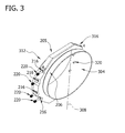
- Fig. 3 is a perspective schematic view of sensor assembly 200 taken along area 3 (shown in Fig. 2 ).
- Collar 204 includes exterior surface 205 and an interior surface 304 that is opposite surface 205. Portion 206 of exterior surface 205 substantially circumscribes interior surface 304.
- collar 204 is formed symmetrically about a centerline or axis of symmetry 308 that extends therethrough such that a first portion 312 and a second portion 316 each extend outwardly from centerline 308.
- collar first portion 312 is aligned substantially symmetrically with respect to collar second portion 316 and with respect to centerline 308.
- first openings 216 are defined in collar first portion 312. More specifically, each first opening 216 extends from exterior surface 205 to interior surface 304 of collar first portion 312. Collar 204 also includes at least a second opening 320 defined therein. More specifically, in the example embodiment, collar 204 includes four second openings 320 that extend through collar second portion 316 from exterior surface 205 to interior surface 304. In the example embodiment, the number of first openings 216 defined within collar first portion 312 is equal to the number of second openings 320 defined within collar second portion 316. More specifically, in the example embodiment, collar first portion 312 includes four first openings 216 and collar second portion 316 includes four second openings 320.
- collar first and second portion 312 and 316 may have any number of openings 216 that enable assembly 200 to function as described herein.
- Collar 204 may be manufactured with openings 216 and 320 and collar 204 may be subsequently welded onto pipeline 116 (shown in Fig. 1 ).
- sensors 220 are at least partially inserted within first openings 216 and second openings 320. More specifically, each sensor 220 is inserted within a respective first opening 216 and a respective second opening 320 such that each sensor extends from collar exterior surface 205 to collar interior surface 304. In the example embodiment, four sensors 220 are inserted at least partially within four different first openings 216 of first portion 312, and four sensors 220 are each inserted at least partially within four different second openings 320 of collar second portion 316.
- Fig. 4 is a cross-sectional schematic view of sensor assembly 200 and taken along line 4-4 (shown in Fig. 3 ).
- openings 216 are aligned substantially parallel to each other within collar first portion 312.
- second openings 320 are aligned substantially parallel with respect to each other within collar second portion 316.
- first openings 216 are aligned substantially coaxially with respect to second openings 320. More specifically, each respective first opening 216 is aligned substantially coaxially with respect to each respective second opening 320. Such an alignment and orientation enables any sensor 220 that is inserted at least partially within first opening 216 to be aligned substantially coaxially with respect to another sensor 220 that is inserted at least partially within second opening 320.
- sensors 220 includes a first sensor 412 that is at least partially inserted within first opening 216 and a second sensor 416 that is at least partially inserted within second opening 320.
- the alignment and orientation of first opening 216 with respect to second opening 320 enables first sensor 412 to be aligned substantially coaxially with respect to second sensor 416.
- the alignment and orientation of first opening 216 with respect to second opening 320 enables second sensor 416 to be downstream of first sensor 412 when assembly 200 is coupled to pipeline 116 (shown in Fig. 1 ).
- first sensor 412 may be downstream of second sensor 416 when assembly 200 is coupled to pipeline 116.
- fluid transport system 100 receives natural gas via inlet pipeline 110 (shown in Fig. 1 ) at a first predetermined pressure.
- the gas channeled to assembly 102 (shown in Fig. 1 ) via suction fixture 108 (shown in Fig. 1 ) is compressed to a greater density and smaller volume at a second predetermined pressure that is higher than the first predetermined pressure.
- the compressed gas is then discharged to outlet pipeline 116 via discharge fixture 114.
- first sensor 412 detects a rate of flow of the gas and transmits a signal to second sensor 416.
- Second sensor 416 receives the signal and then transmits a reflective signal to first sensor 412. Because first sensor 412 is aligned substantially coaxially with respect to second sensor 416, the signals that are transmitted between first sensor 412 and second sensor 416 are transmitted at a relatively rapid rate. The rapid transmission rate enables sensors 412 and 416 to provide substantially accurate signals to one another.
- each of the signals that are transmitted from first sensor 412 to second sensor 416 are then transmitted to the flow meter (not shown). The flow meter then calculates the velocity and volumetric flow rate of the gas within pipeline 116.
- the above-described sensor assembly may be used with fluid transport systems to enable more accurate measurements of the rate of flow.
- the sensor assembly includes an annular collar that is coupled to at least two sensors.
- the collar includes at least two openings that are sized to receive a sensor therein.
- the collar substantially circumscribes the pipeline and is configured to secure the sensors to the pipeline such that the sensors are substantially coaxially aligned with each other. Such an orientation enables the sensors to provide substantially accurate measurements of the flow rate of the fluid within the pipeline.
- Example embodiments of systems, apparatus, and methods are described above in detail.
- the systems, apparatus, and methods are not limited to the specific embodiments described herein, but rather, components of the sensor assembly and/or steps of assembling the sensor assembly may be utilized independently and separately from other components and/or steps described herein.
- the sensor assembly may also be used in combination with other systems and methods, and is not limited to practice with only a fluid transport system as described herein. Rather, the example embodiment can be implemented and utilized in connection with many other systems.
Landscapes
- Physics & Mathematics (AREA)
- Electromagnetism (AREA)
- Fluid Mechanics (AREA)
- General Physics & Mathematics (AREA)
- Measuring Volume Flow (AREA)
Abstract
Description
- The field of the invention relates generally to fluid transport systems and, more particularly, sensor assemblies that can be used with a pipeline in a fluid transport system.
- Fluid transport is used in a variety of different industries including, but not limited to, the chemical, oil, and gas industries. In at least some known fluid transport applications, fluids are transported from on-shore or off-shore locations to processing plants for subsequent use. Moreover, fluid transport is used in hydrocarbon processing industries and chemical industries, and to facilitate distribution to end-users. Mechanical drives (i.e., gas turbines) and/or electrical machines (i.e., electrically-powered drive motors, or electric drives) may be used to transport fluids. For example, at least some known fluid transport systems use fluid transport apparatus such as compressors, fans and/or pumps that are driven by gas turbines. Often turbines drive the associated fluid transport apparatus via a gearbox that controls a gas turbine output drive shaft speed to a predetermined apparatus drive shaft speed.
- When mechanical drives and/or electrical machinery are used to transport fluids within pipelines of fluid transport systems, it is necessary to determine the flow rate of the fluid within the pipelines. More specifically, maintaining the stability of the flow rate of fluid channeled through the pipelines is desired.
- Several known devices may be used to measure the flow rate of fluids in fluid transport systems. For example, at least some known flow meters and/or sensors may be welded within a pipeline to measure the flow of fluid within the pipeline. In some of such systems, transducers or sensors are inserted into the openings formed within the pipeline. However, such devices may be problematic as the welding may deform the pipeline and/or the pipeline may be damaged when the openings are formed. Moreover, the alignment of the transducers or sensors inserted into the openings may shift during operation. Because of the possibility of alignment shifts, the accuracy of the measurements provided by such transducers or sensors may be limited.
- In one embodiment, a sensor assembly for use with a fluid transport system is provided. The sensor assembly includes at least two sensors that are configured to measure a rate of flow of a fluid channeled through a pipeline of the fluid transport system. Moreover, the sensor assembly includes an annular collar that is coupled to the two sensors. The collar includes at least a first opening and at least a second opening defined therein. The first opening and the second opening are each sized to receive the two sensors therein such that the two sensors are substantially coaxially aligned with each other. A first sensor of the two sensors is positioned downstream from a second sensor of the two sensors.
- In another embodiment, a fluid transport system is provided. The fluid transport system includes at least one pipeline and a sensor assembly that substantially circumscribes the pipeline. The sensor assembly includes at least two sensors that are configured to measure a rate of flow of a fluid channeled through the pipeline. Moreover, the sensor assembly includes an annular collar that is coupled to the two sensors. The collar includes at least a first opening and at least a second opening defined therein. The first opening and the second opening are each sized to receive the two sensors therein such that the two sensors are substantially coaxially aligned with each other. A first sensor of the two sensors is positioned downstream from a second sensor of the two sensors
- In yet another embodiment, a method of assembling a sensor assembly for use with a fluid transport system is provided. The method includes coupling at least two sensors configured to measure a rate of flow of a fluid within a pipeline of the fluid transport system to an annular collar. The annular collar includes at least a first opening and at least a second opening defined therein. Moreover, the first opening and the second opening are configured to receive the sensors therein such that the two sensors are substantially coaxially aligned with each other. A first sensor of the two sensors is positioned downstream from a second sensor of the two sensors.
-
-
Fig. 1 is a cross-sectional schematic view of a portion of an example fluid transport system; -
Fig. 2 is a schematic view of an example sensor assembly that may be used with the fluid transport system shown inFig. 1 and taken alongarea 2; -
Fig. 3 is a perspective schematic view of the sensor assembly shown inFig. 2 and taken alongarea 3; and -
Fig. 4 is a cross-sectional schematic view of the sensor assembly shown inFig. 3 and taken along line 4-4. - The example apparatus, systems, and methods described herein overcome at least some disadvantages of known techniques and sensor systems used to measure the flow rate of fluids within fluid transport systems by providing a sensor assembly that includes sensors that are securely coupled to a pipeline of a fluid transport system such that substantially accurate measurements of the flow rate of a fluid channeled within the pipeline are facilitated. In the example embodiment, the sensor assembly includes an annular collar that is coupled to at least two sensors. The collar includes at least two openings that are sized to receive a sensor therein. The collar substantially circumscribes the pipeline and is configured to secure the sensors to the pipeline such that the sensors are substantially coaxially aligned with each other. Such an orientation enables the sensors to provide substantially accurate measurements of the flow rate of the fluid within the pipeline.
-
Figure 1 is a cross-sectional schematic view of a portion of an examplefluid transport system 100. In the example embodiment,system 100 is a submerged natural gas compressing station that includes afluid transport assembly 102. While the example embodiment includes a natural gas compressing station, the present invention is not limited to any one particular system, and one of ordinary skill in the art will appreciate that the current invention may be used in connection with other fluid transport systems. - In the example embodiment,
system 100 includes a housing 106 and thatassembly 102 is secured within housing 106. In the example embodiment, housing 106 includes anassembly suction fixture 108 that is coupled in flow communication to aninlet pipeline 110. In the example embodiment,system 100 also includes anassembly end piece 112 that is coupled to housing 106 such thatpiece 112 extends outward from housing 106.End piece 112 enclosesassembly 102 withinsystem 100 subsequent to insertion ofassembly 102 into housing 106 and includes anassembly discharge fixture 114 that is coupled in flow communication to anoutlet pipeline 116 that is substantially similar toinlet pipeline 110. - In the example embodiment,
assembly 102 includes arotatable drive shaft 128 that is rotatably coupled to a rotor (not shown). Moreover,assembly 102 includes at least oneassembly stage 130. The rotor andshaft 128 are rotatable about an axis ofrotation 132. In the example embodiment, asensor assembly 200 is coupled tooutlet pipeline 116. Although in the exampleembodiment sensor assembly 200 is illustrated as being coupled topipeline 116, it should be noted thatsensor assembly 200 is not limited to being coupled to any particular pipeline withinsystem 100, and one of ordinary skill in the art will appreciate thatsensor assembly 200 may be used with any pipeline withinsystem 100.Sensor assembly 200, in the example embodiment, includes at least two sensors (not shown inFig. 1 ) that are used to measure a rate of flow of transport fluid channeled throughpipeline 116.Sensor assembly 200, in the example embodiment, is manufactured such thatsensor assembly 200 may be sized and shaped to be coupled to any substantially large pipeline, such as a pipeline that has a diameter of at least approximately 24 inches. - During operation, in the example embodiment,
system 100 receives natural gas viainlet pipeline 110 at a first predetermined pressure. The gas is channeled toassembly 102 viasuction fixture 108 and is compressed to a greater density and smaller volume at a second predetermined pressure that is higher than the first predetermined pressure. The compressed gas is discharged tooutlet pipeline 116 viadischarge fixture 114. The rate of flow of the fluid is measured via the sensors that are included insensor assembly 200. -
Fig. 2 is a side schematic view ofsensor assembly 200 coupled to a portion ofoutlet pipeline 116 and taken along area 2 (shown inFig. 1 ). In the example embodiment,sensor assembly 200 includes anannular collar 204 that is substantially elliptical.Annular collar 204 may be formed from any material, such as, but not limited to, a metallic material and/or a metal alloy material, that enables predetermined operational parameters associated with the fluid being transported to be satisfied and that enables assembly 200 to function as described herein. - In the example embodiment,
collar 204 includes an interior surface (not shown inFig. 2 ) and anexterior surface 205.Exterior surface 205 has afirst portion 206 that substantially circumscribes the interior surface ofannular collar 204.Exterior surface 205 also has asecond portion 207 that extends outwardly fromfirst portion 206. In the example embodiment,first portion 206 is formed integrally withsecond portion 207. Alternatively,first portion 206 may be coupled tosecond portion 207. -
Collar 204, in the example embodiment, is coupled tooutlet pipeline 116 such thatcollar 204 substantially circumscribes at least a portion ofoutlet pipeline 116. More specifically, a cut (not shown) is formed throughoutlet pipeline 116 between afirst portion 208 and asecond portion 212. In the example embodiment, the cut is formed using a cutting tool, such as a saw. Alternatively, the cut may be formed using any known method that enablessensor assembly 200 to function as described herein. In the example embodiment,annular collar 204 is coupled topipeline 116 such that pipefirst portion 208 and pipesecond portion 212 are securely coupled viacollar 204. Alternatively,collar 204 may be coupled topipeline 116 in any manner that enablessensor assembly 200 to function as described herein. -
Collar 204 includes at least afirst opening 216 that extends throughcollar 204. More specifically, in the example embodiment,collar 204 includes fourfirst openings 216. Alternatively,collar 204 includes any number of openings that enablessensor assembly 200 to function as described herein. Moreover,collar 204 also includes at least a second opening (not shown inFig. 2 ) that is described in more detail below. In the example embodiment,collar 204 is coupled tooutlet pipeline 116 such that eachfirst opening 216 and each second opening are positioned at a 45 degree angle with respect to the fluid flow withinpipeline 116. - In the example embodiment,
sensor assembly 200 includes at least twosensors 220 that are used to measure a rate of flow of transport fluid channeled throughpipeline 116. In the example embodiment,sensors 220 are compact ultrasonic transducers that transmit and receive ultrasonic pluses through the fluid being channeled throughpipeline 116. Alternatively,sensors 220 may be any type of sensor that enables fluid flow rates to be measured and that fit withinsensor assembly 200 to enableassembly 200 to function as described herein. - In the example embodiment, each
sensor 220 is coupled tocollar 204. More specifically, eachsensor 220 is at least partially inserted within arespective opening 216. As such, in the example embodiment, each of foursensors 220 shown inFig. 2 are each at least partially inserted within a respectivefirst opening 216. Moreover, in the example embodiment,sensors 220 are also coupled to a flow meter (not shown) that is used to calculate the velocity and volumetric flow rate of the fluid. Alternatively,sensors 220 may be coupled to any other device that can measure fluid flow rates withinpipeline 116 and that enablessensor assembly 200 to function as described herein. The flow meter may be a component withinassembly 200 or a separate structure that is coupled toassembly 200. -
Fig. 3 is a perspective schematic view ofsensor assembly 200 taken along area 3 (shown inFig. 2 ).Collar 204 includesexterior surface 205 and aninterior surface 304 that isopposite surface 205.Portion 206 ofexterior surface 205 substantially circumscribesinterior surface 304. Moreover,collar 204 is formed symmetrically about a centerline or axis ofsymmetry 308 that extends therethrough such that afirst portion 312 and asecond portion 316 each extend outwardly fromcenterline 308. In the example embodiment, collarfirst portion 312 is aligned substantially symmetrically with respect to collarsecond portion 316 and with respect tocenterline 308. - In the example embodiment,
first openings 216 are defined in collarfirst portion 312. More specifically, eachfirst opening 216 extends fromexterior surface 205 tointerior surface 304 of collarfirst portion 312.Collar 204 also includes at least asecond opening 320 defined therein. More specifically, in the example embodiment,collar 204 includes foursecond openings 320 that extend through collarsecond portion 316 fromexterior surface 205 tointerior surface 304. In the example embodiment, the number offirst openings 216 defined within collarfirst portion 312 is equal to the number ofsecond openings 320 defined within collarsecond portion 316. More specifically, in the example embodiment, collarfirst portion 312 includes fourfirst openings 216 and collarsecond portion 316 includes foursecond openings 320. Alternatively, collar first andsecond portion openings 216 that enable assembly 200 to function as described herein.Collar 204 may be manufactured withopenings collar 204 may be subsequently welded onto pipeline 116 (shown inFig. 1 ). - In the example embodiment,
sensors 220 are at least partially inserted withinfirst openings 216 andsecond openings 320. More specifically, eachsensor 220 is inserted within a respectivefirst opening 216 and a respectivesecond opening 320 such that each sensor extends from collarexterior surface 205 to collarinterior surface 304. In the example embodiment, foursensors 220 are inserted at least partially within four differentfirst openings 216 offirst portion 312, and foursensors 220 are each inserted at least partially within four differentsecond openings 320 of collarsecond portion 316. -
Fig. 4 is a cross-sectional schematic view ofsensor assembly 200 and taken along line 4-4 (shown inFig. 3 ). In the example embodiment,openings 216 are aligned substantially parallel to each other within collarfirst portion 312. Similarly,second openings 320 are aligned substantially parallel with respect to each other within collarsecond portion 316. - Moreover, in the example embodiment,
first openings 216 are aligned substantially coaxially with respect tosecond openings 320. More specifically, each respectivefirst opening 216 is aligned substantially coaxially with respect to each respectivesecond opening 320. Such an alignment and orientation enables anysensor 220 that is inserted at least partially withinfirst opening 216 to be aligned substantially coaxially with respect to anothersensor 220 that is inserted at least partially withinsecond opening 320. - For example, in the example embodiment,
sensors 220 includes afirst sensor 412 that is at least partially inserted withinfirst opening 216 and asecond sensor 416 that is at least partially inserted withinsecond opening 320. The alignment and orientation offirst opening 216 with respect tosecond opening 320 enablesfirst sensor 412 to be aligned substantially coaxially with respect tosecond sensor 416. The alignment and orientation offirst opening 216 with respect tosecond opening 320 enablessecond sensor 416 to be downstream offirst sensor 412 whenassembly 200 is coupled to pipeline 116 (shown inFig. 1 ). Alternatively,first sensor 412 may be downstream ofsecond sensor 416 whenassembly 200 is coupled topipeline 116. - During operation, fluid transport system 100 (shown in
Fig. 1 ) receives natural gas via inlet pipeline 110 (shown inFig. 1 ) at a first predetermined pressure. The gas channeled to assembly 102 (shown inFig. 1 ) via suction fixture 108 (shown inFig. 1 ) is compressed to a greater density and smaller volume at a second predetermined pressure that is higher than the first predetermined pressure. The compressed gas is then discharged tooutlet pipeline 116 viadischarge fixture 114. - In the example embodiment, as gas is channeled through
outlet pipeline 116,first sensor 412 detects a rate of flow of the gas and transmits a signal tosecond sensor 416.Second sensor 416 receives the signal and then transmits a reflective signal tofirst sensor 412. Becausefirst sensor 412 is aligned substantially coaxially with respect tosecond sensor 416, the signals that are transmitted betweenfirst sensor 412 andsecond sensor 416 are transmitted at a relatively rapid rate. The rapid transmission rate enablessensors first sensor 412 tosecond sensor 416 are then transmitted to the flow meter (not shown). The flow meter then calculates the velocity and volumetric flow rate of the gas withinpipeline 116. - As compared to known systems, apparatus, and methods that are used to measure the flow rate of fluids in fluid transport systems, the above-described sensor assembly may be used with fluid transport systems to enable more accurate measurements of the rate of flow. More specifically, in the example embodiment, the sensor assembly includes an annular collar that is coupled to at least two sensors. The collar includes at least two openings that are sized to receive a sensor therein. The collar substantially circumscribes the pipeline and is configured to secure the sensors to the pipeline such that the sensors are substantially coaxially aligned with each other. Such an orientation enables the sensors to provide substantially accurate measurements of the flow rate of the fluid within the pipeline.
- Example embodiments of systems, apparatus, and methods are described above in detail. The systems, apparatus, and methods are not limited to the specific embodiments described herein, but rather, components of the sensor assembly and/or steps of assembling the sensor assembly may be utilized independently and separately from other components and/or steps described herein. For example, the sensor assembly may also be used in combination with other systems and methods, and is not limited to practice with only a fluid transport system as described herein. Rather, the example embodiment can be implemented and utilized in connection with many other systems.
- Although specific features of various embodiments of the invention may be shown in some drawings and not in others, this is for convenience only. In accordance with the principles of the invention, any feature of a drawing may be referenced and/or claimed in combination with any feature of any other drawing.
- This written description uses examples to disclose the invention, including the best mode, and also to enable any person skilled in the art to practice the invention, including making and using any devices or systems and performing any incorporated methods. The patentable scope of the invention is defined by the claims, and may include other examples that occur to those skilled in the art. Such other examples are intended to be within the scope of the claims if they have structural elements that do not differ from the literal language of the claims, or if they include equivalent structural elements with insubstantial differences from the literal language of the claims.
Claims (15)
- A sensor assembly (200) for use with a fluid transport system (100), said sensor assembly comprising:at least two sensors (220) configured to measure a rate of flow of a fluid channeled through a pipeline (116) of the fluid transport system; andan annular collar (204) coupled to said at least two sensors, said collar comprises at least a first opening (216) and at least a second opening (320) defined therein, each of said at least a first opening and said at least a second opening is sized to receive one of said at least two sensors therein such that said at least two sensors are substantially coaxially aligned with each other, a first sensor (412) of said at least two sensors is positioned downstream from a second sensor (416) of said at least two sensors.
- A sensor assembly (200) in accordance with Claim 1, wherein said at least a first opening (216) is substantially coaxially aligned with respect to said at least a second opening (320).
- A sensor assembly (200) in accordance with Claim 1 or Claim 2, wherein said first sensor (412) is inserted at least partially within said at least a first opening (216) and said second sensor (416) is inserted at least partially within said at least a second opening.
- A sensor assembly (200) in accordance with Claim 1, 2 or 3, wherein said collar (204) comprises an exterior surface (205) and an interior surface (304) opposite said exterior surface.
- A sensor assembly (200) in accordance with Claim 4, wherein said at least a first opening (216) and said at least a second opening (320) each extend from said exterior surface (205) to said interior surface (304).
- A sensor assembly (200) in accordance with Claim 4 or Claim 5, wherein said exterior surface (205) comprises:a first portion (206) substantially circumscribing said interior surface (304);
anda second portion (207) extending outwardly from said first portion. - A sensor assembly (200) in accordance with Claim 6, wherein said second portion is formed integrally with said first portion (206).
- A fluid transport system (100) comprising:at least one pipeline (116); anda sensor assembly (200) substantially circumscribing said at least one pipeline, said sensor assembly in accordance with any one of Claims 1 to 7.
- A method of assembling a sensor assembly for use with a fluid transport system, said method comprising:coupling at least two sensors (220) configured to measure a rate of flow of a fluid within a pipeline (116) of the fluid transport system to an annular collar (204) that includes at least a first opening (216) and at least a second opening (320) defined therein; andconfiguring each of the at least a first opening (216) and the at least a second opening to receive one of the at least two sensors (220) therein such that the at least two sensors (220) are substantially coaxially aligned with each other, a first sensor of the at least two sensors is positioned downstream from a second sensor of the at least two sensors (220).
- A method in accordance with Claim 9, further comprising aligning the at least a first opening to be substantially coaxial with respect to the at least a second opening.
- A method in accordance with Claim 9 or Claim 10, wherein coupling at least two sensors further comprises coupling the first sensor and the second sensor to the annular collar (204).
- A method in accordance with Claim 11, further comprising:inserting the first sensor at least partially within the at least a first opening (216); andinserting the second sensor at least partially within the at least a second opening (320).
- A method in accordance with any one of Claims 9 to 12, wherein coupling at least two sensors (220) further comprises coupling the at least two sensors to an annular collar (204) that includes an exterior surface and an interior surface.
- A method in accordance with Claim 13, further comprising configuring the at least a first opening (216) and the at least a second opening (320) to extend from the exterior surface to the interior surface.
- A method in accordance with Claim 14, wherein coupling the at least two sensors (220) to an annular collar (204) that includes an exterior surface and an interior surface further comprises coupling the at least two sensors (220) to an annular collar (204) that includes an exterior surface that includes a first portion substantially circumscribing the interior surface and a second portion extending outwardly from the first portion.
Applications Claiming Priority (1)
| Application Number | Priority Date | Filing Date | Title |
|---|---|---|---|
| US13/152,504 US8438936B2 (en) | 2011-06-03 | 2011-06-03 | Sensor assembly including a collar for mounting sensors to a pipeline |
Publications (1)
| Publication Number | Publication Date |
|---|---|
| EP2530437A1 true EP2530437A1 (en) | 2012-12-05 |
Family
ID=46229255
Family Applications (1)
| Application Number | Title | Priority Date | Filing Date |
|---|---|---|---|
| EP12170445A Withdrawn EP2530437A1 (en) | 2011-06-03 | 2012-06-01 | Sensor assembly for use with a fluid transport system and method of assembling same |
Country Status (3)
| Country | Link |
|---|---|
| US (1) | US8438936B2 (en) |
| EP (1) | EP2530437A1 (en) |
| CN (1) | CN102809396A (en) |
Families Citing this family (3)
| Publication number | Priority date | Publication date | Assignee | Title |
|---|---|---|---|---|
| JP4875780B2 (en) * | 2010-06-22 | 2012-02-15 | 株式会社泉技研 | Ultrasonic flow measuring device and ultrasonic flow measuring method |
| WO2016205632A1 (en) * | 2015-06-17 | 2016-12-22 | Berkeley Springs Instruments Llc | Transducer mounting apparatus |
| EP3550291A1 (en) * | 2018-04-05 | 2019-10-09 | Georg Fischer Rohrleitungssysteme AG | Fastening device for measuring devices on pipes |
Citations (4)
| Publication number | Priority date | Publication date | Assignee | Title |
|---|---|---|---|---|
| EP0036658A1 (en) * | 1980-03-25 | 1981-09-30 | Fuji Electric Co. Ltd. | Ultrasonic device for measuring the flow of a fluid in a conduit |
| US4374477A (en) * | 1980-03-25 | 1983-02-22 | Fuji Electric Co., Ltd. | Ultrasonic measuring device |
| US20070151363A1 (en) * | 2005-12-30 | 2007-07-05 | Honeywell International Inc. | Non-invasive sensing technique for measuring gas flow and temperature |
| WO2011020143A1 (en) * | 2009-08-18 | 2011-02-24 | Rubicon Research Pty Ltd | Flow meter assembly, gate assemblies and methods of flow measurement |
Family Cites Families (16)
| Publication number | Priority date | Publication date | Assignee | Title |
|---|---|---|---|---|
| US3964308A (en) | 1973-09-04 | 1976-06-22 | Scarpa Laboratories, Inc. | Ultrasonic flowmeter |
| US3906791A (en) * | 1973-10-01 | 1975-09-23 | Panametrics | Area averaging ultrasonic flowmeters |
| US4004461A (en) * | 1975-11-07 | 1977-01-25 | Panametrics, Inc. | Ultrasonic measuring system with isolation means |
| US4098117A (en) * | 1977-04-29 | 1978-07-04 | Joseph Baumoel | Open channel flow transducer for sewerage system |
| US4286470A (en) * | 1979-10-19 | 1981-09-01 | Lfe Corporation | Clamp-on ultrasonic transducer |
| JPH01148912A (en) | 1987-12-04 | 1989-06-12 | Agency Of Ind Science & Technol | Ring vortex flowmeter |
| JPH0778438B2 (en) * | 1988-07-08 | 1995-08-23 | エンドレス ウント ハウザー フローテック アクチエンゲゼルシヤフト | Ultrasonic flow rate measuring method and device |
| US5437194A (en) * | 1991-03-18 | 1995-08-01 | Panametrics, Inc. | Ultrasonic transducer system with temporal crosstalk isolation |
| JP3246851B2 (en) | 1995-04-10 | 2002-01-15 | 東京計装株式会社 | Ultrasonic flowmeter detector |
| US6128072A (en) | 1998-04-23 | 2000-10-03 | Nova Gas Transmission Ltd. | Optical flow meter integrally mounted to a rigid plate with direct optical access to the interior of a pipe |
| EP1182431A4 (en) | 1999-03-17 | 2006-06-14 | Matsushita Electric Industrial Co Ltd | ULTRASOUND FLOWMETER |
| US6732595B2 (en) * | 2002-07-18 | 2004-05-11 | Panametrics, Inc. | Method of and system for determining the mass flow rate of a fluid flowing in a conduit |
| JP4355792B2 (en) * | 2002-08-29 | 2009-11-04 | 東京瓦斯株式会社 | Thermal flow meter |
| DE102004060065B4 (en) | 2004-12-14 | 2016-10-20 | Robert Bosch Gmbh | Ultrasonic flow meter with guide elements |
| DE102004061404A1 (en) | 2004-12-21 | 2006-07-06 | Robert Bosch Gmbh | Ultrasonic flow meter and method for flow measurement by means of ultrasound |
| US7823462B2 (en) | 2007-12-14 | 2010-11-02 | Cameron International Corporation | Turbulence conditioner for transit time ultrasonic flow meters and method |
-
2011
- 2011-06-03 US US13/152,504 patent/US8438936B2/en not_active Expired - Fee Related
-
2012
- 2012-06-01 EP EP12170445A patent/EP2530437A1/en not_active Withdrawn
- 2012-06-04 CN CN2012101802886A patent/CN102809396A/en active Pending
Patent Citations (4)
| Publication number | Priority date | Publication date | Assignee | Title |
|---|---|---|---|---|
| EP0036658A1 (en) * | 1980-03-25 | 1981-09-30 | Fuji Electric Co. Ltd. | Ultrasonic device for measuring the flow of a fluid in a conduit |
| US4374477A (en) * | 1980-03-25 | 1983-02-22 | Fuji Electric Co., Ltd. | Ultrasonic measuring device |
| US20070151363A1 (en) * | 2005-12-30 | 2007-07-05 | Honeywell International Inc. | Non-invasive sensing technique for measuring gas flow and temperature |
| WO2011020143A1 (en) * | 2009-08-18 | 2011-02-24 | Rubicon Research Pty Ltd | Flow meter assembly, gate assemblies and methods of flow measurement |
Also Published As
| Publication number | Publication date |
|---|---|
| CN102809396A (en) | 2012-12-05 |
| US8438936B2 (en) | 2013-05-14 |
| US20120304759A1 (en) | 2012-12-06 |
Similar Documents
| Publication | Publication Date | Title |
|---|---|---|
| US8714309B2 (en) | High pressure lubrication system | |
| CA2786401C (en) | Ultrasonic flow meter, transducer assembly, and methods of manufacturing the same | |
| EP3120120B1 (en) | Pipe assembly with stepped flow conditioners | |
| KR102026276B1 (en) | Flow volume measurement device for turbo compressor, and turbo compressor | |
| EP2641064A1 (en) | Chordal gas flowmeter with transducers installed outside the pressure boundary, housing and method | |
| US8438936B2 (en) | Sensor assembly including a collar for mounting sensors to a pipeline | |
| US20150240843A1 (en) | Flow conditioner with integral vanes | |
| EP2444781A1 (en) | Ultrasonic measurement of flow velocity | |
| CN102792133A (en) | Ultrasonic flow meter with transducer assembly having a rotatable receptacle and elbow connector | |
| CN107013492B (en) | Compressor housing for air cycle machine | |
| CN205449170U (en) | Gaseous turbine flowmeter of intelligence with self -diagnostic function | |
| US9689886B2 (en) | Flow angle probe with a passively rotating vane | |
| EP2423511A2 (en) | A supersonic compressor rotor and method of assembling same | |
| CN110174147A (en) | Oil-water two-phase flow real-time measurement apparatus and method based on dynamic rotation spiral Flow Technique | |
| EP2333495A1 (en) | Ultrasonic consumption flow meter with connection piece | |
| CN112814916A (en) | Horizontal test model pump of axial-flow pump | |
| WO2021104892A1 (en) | Debris detection system | |
| JP7199186B2 (en) | Turbo-type pump, blade tip clearance measurement device for turbo-type pump, and blade tip clearance measurement method | |
| CN109098965A (en) | A kind of detection device of oil pump volumetric efficiency | |
| CN103547807A (en) | Pump, pump system and method for pumping a medium | |
| CN203688002U (en) | Novel gas turbine flowmeter | |
| Jin et al. | Excitation of blade vibration due to surge of centrifugal compressors | |
| EP3348971A1 (en) | Harvesting energy on a meter device | |
| EP3964801B1 (en) | An ultrasonic flow meter flow tube and a method for manufacturing the flow tube | |
| KR101479648B1 (en) | Volumetric flow meter |
Legal Events
| Date | Code | Title | Description |
|---|---|---|---|
| PUAI | Public reference made under article 153(3) epc to a published international application that has entered the european phase |
Free format text: ORIGINAL CODE: 0009012 |
|
| AK | Designated contracting states |
Kind code of ref document: A1 Designated state(s): AL AT BE BG CH CY CZ DE DK EE ES FI FR GB GR HR HU IE IS IT LI LT LU LV MC MK MT NL NO PL PT RO RS SE SI SK SM TR |
|
| AX | Request for extension of the european patent |
Extension state: BA ME |
|
| 17P | Request for examination filed |
Effective date: 20130605 |
|
| RBV | Designated contracting states (corrected) |
Designated state(s): AL AT BE BG CH CY CZ DE DK EE ES FI FR GB GR HR HU IE IS IT LI LT LU LV MC MK MT NL NO PL PT RO RS SE SI SK SM TR |
|
| STAA | Information on the status of an ep patent application or granted ep patent |
Free format text: STATUS: THE APPLICATION IS DEEMED TO BE WITHDRAWN |
|
| 18D | Application deemed to be withdrawn |
Effective date: 20170103 |