EP2530427A1 - Portable gauge and method for measuring tape gaps - Google Patents
Portable gauge and method for measuring tape gaps Download PDFInfo
- Publication number
- EP2530427A1 EP2530427A1 EP12275068A EP12275068A EP2530427A1 EP 2530427 A1 EP2530427 A1 EP 2530427A1 EP 12275068 A EP12275068 A EP 12275068A EP 12275068 A EP12275068 A EP 12275068A EP 2530427 A1 EP2530427 A1 EP 2530427A1
- Authority
- EP
- European Patent Office
- Prior art keywords
- gauge
- tape
- strips
- along
- frame
- Prior art date
- Legal status (The legal status is an assumption and is not a legal conclusion. Google has not performed a legal analysis and makes no representation as to the accuracy of the status listed.)
- Granted
Links
- 238000000034 method Methods 0.000 title claims description 33
- 239000002131 composite material Substances 0.000 claims abstract description 34
- 238000005259 measurement Methods 0.000 claims description 59
- 238000007689 inspection Methods 0.000 claims description 8
- 238000005096 rolling process Methods 0.000 claims description 8
- 238000004519 manufacturing process Methods 0.000 description 14
- 230000008569 process Effects 0.000 description 7
- 238000010586 diagram Methods 0.000 description 6
- 239000000463 material Substances 0.000 description 3
- 230000003287 optical effect Effects 0.000 description 3
- 230000008901 benefit Effects 0.000 description 2
- 230000008878 coupling Effects 0.000 description 2
- 238000010168 coupling process Methods 0.000 description 2
- 238000005859 coupling reaction Methods 0.000 description 2
- 238000012423 maintenance Methods 0.000 description 2
- 230000001960 triggered effect Effects 0.000 description 2
- 238000004458 analytical method Methods 0.000 description 1
- 230000001419 dependent effect Effects 0.000 description 1
- 238000013461 design Methods 0.000 description 1
- 230000007613 environmental effect Effects 0.000 description 1
- 230000010354 integration Effects 0.000 description 1
- 238000000691 measurement method Methods 0.000 description 1
- 230000007246 mechanism Effects 0.000 description 1
- 230000004048 modification Effects 0.000 description 1
- 238000012986 modification Methods 0.000 description 1
- 230000008520 organization Effects 0.000 description 1
- 238000009419 refurbishment Methods 0.000 description 1
- 238000012552 review Methods 0.000 description 1
- 230000000007 visual effect Effects 0.000 description 1
Images


Classifications
-
- G—PHYSICS
- G01—MEASURING; TESTING
- G01B—MEASURING LENGTH, THICKNESS OR SIMILAR LINEAR DIMENSIONS; MEASURING ANGLES; MEASURING AREAS; MEASURING IRREGULARITIES OF SURFACES OR CONTOURS
- G01B11/00—Measuring arrangements characterised by the use of optical techniques
- G01B11/02—Measuring arrangements characterised by the use of optical techniques for measuring length, width or thickness
-
- G—PHYSICS
- G01—MEASURING; TESTING
- G01B—MEASURING LENGTH, THICKNESS OR SIMILAR LINEAR DIMENSIONS; MEASURING ANGLES; MEASURING AREAS; MEASURING IRREGULARITIES OF SURFACES OR CONTOURS
- G01B11/00—Measuring arrangements characterised by the use of optical techniques
- G01B11/14—Measuring arrangements characterised by the use of optical techniques for measuring distance or clearance between spaced objects or spaced apertures
-
- G—PHYSICS
- G01—MEASURING; TESTING
- G01B—MEASURING LENGTH, THICKNESS OR SIMILAR LINEAR DIMENSIONS; MEASURING ANGLES; MEASURING AREAS; MEASURING IRREGULARITIES OF SURFACES OR CONTOURS
- G01B11/00—Measuring arrangements characterised by the use of optical techniques
- G01B11/24—Measuring arrangements characterised by the use of optical techniques for measuring contours or curvatures
- G01B11/25—Measuring arrangements characterised by the use of optical techniques for measuring contours or curvatures by projecting a pattern, e.g. one or more lines, moiré fringes on the object
-
- G—PHYSICS
- G01—MEASURING; TESTING
- G01B—MEASURING LENGTH, THICKNESS OR SIMILAR LINEAR DIMENSIONS; MEASURING ANGLES; MEASURING AREAS; MEASURING IRREGULARITIES OF SURFACES OR CONTOURS
- G01B11/00—Measuring arrangements characterised by the use of optical techniques
Definitions
- the present disclosure generally relates to the fabrication of composite structures formed from laying down composite tape strips, and deals more particularly with a portable gauge and method for measuring the gaps between the tape strips, especially after an area of a structure has been reworked.
- CTLs composite tape layup machines
- CTLs composite tape layup machines
- These relatively large and expensive machines use a computer controlled tape placement head to simultaneously lay down multiple strips of composite prepreg tape on a mandrel or other surface.
- the head places the tape strips in substantially parallel relationship and in edge-to-edge contact, however, small gaps may occur between edges of adjacent strips. If these gaps exceed an allowable tolerance, they may affect the quality and/or performance of the completed structure.
- gaps exceed the allowed tolerance, it may be necessary to rework these areas of the structure in order to bring the structure to within manufacturing specifications. Following rework of the tape strips, the areas are re-inspected to assure that tape gaps have been brought to within specified tolerances.
- the tape gap inspection process may be performed by a technician using a hand gauge to make each individual tape gap measurement.
- the technician is required to manually reposition the gauge to each measurement point along the length of a reworked tape.
- the technician kneels and takes a visual gap reading.
- This hand measurement technique is labor intensive and may be impractical for use on large scale structures because of the number of measurements that may be necessary and the time required to complete the measurements. Also, the accuracy of the hand held measurements may be subject to the skill level of the technician.
- Tape gaps may also be measured automatically a using non-contact inspection device integrated into the tape placement head of the CTML, however this solution may require that the CTLM be taken off-line from production to perform the inspection process.
- the resulting machine downtime may reduce production throughput, and may be inefficient where only a single reworked tape strip requires inspection.
- the disclosed embodiments provide a portable gauge and related method for rapidly performing multiple tape gap measurements useful in inspecting reworked sections of large scale composite structures.
- the embodiments may reduce labor costs and avoid interruptions in production flow.
- the portable gauge allows automated triggering, acquisition and analysis of tape gap measurements.
- the gauge employs an active steering system that automatically steers along tape strip edges, thereby allowing the gauge to be moved rapidly while continuous gap measurements are performed.
- a tape gap inspection gauge comprises a measurement system for measuring a gap between adjacent strips of the tape.
- the measurement system includes at least one non-contact sensor for sensing the edge of at least one of the tape strips.
- the gage further comprises a movement system for moving the measurement system along the surface of the tape strips.
- the gauge further includes a frame on which the measurement system is mounted.
- the movement system includes wheels supporting the frame for rolling movement along the tape strip surface, and a steering system on the frame for steering at least one steerable wheel.
- the measurement system may include two laser line projectors for projecting laser lines across the edges of two adjacent tape strips, and two non-contact sensors for detecting the edges of the adjacent tape strips.
- the steering system may include a servo motor and linkage coupled between the servo motor and the steerable wheel.
- a portable gauge for inspecting the surface of a composite structure formed from strips of composite tape.
- the gauge comprises a measurement system for measuring a feature of the strips of the tape, and a movement system adapted to be placed on the surface of the structure for moving the measurement system along the surface.
- the feature may comprise a gap between adjacent tape strips.
- the measurement system may comprise sensors for sensing the edges of adjacent ones of the tape strips, and a computer for calculating the gap based on the location of the sensed edges.
- the measurement system may include a pair of laser line projectors for projecting laser lines across the edges of the adjacent tape strips, and the sensors are positioned to sense 2-D reflections of the projected laser lines from the surface of the structure.
- the invention relates to a portable gauge for inspecting the surface of a composite structure, formed from strips of composite tape, comprising a measurement system for measuring a feature of the strips of the tape, and a movement system adapted to be placed on the surface of the structure for moving the measurement system along the surface.
- the feature may be a gap between adjacent tape strips.
- the measurement system may includes sensors for sensing the edges of adjacent tape strips and a computer coupled with the sensors for calculating the gap based on the location of the sensed edges.
- the measurement system may include a pair of laser line projectors for projecting laser lines across the edges of the adjacent tape strips.
- the sensors can be positioned to sense 2-D reflections of the projected laser lines from the surface of the structure.
- the above described portable gauge may further comprise a frame having the measurement system mounted thereon, and wherein the movement system may include members for supporting the frame on and movement along the surface of the structure.
- the movement system may include an active steering system for automatically steering the movement of the gauge along the tape strip surface.
- the measurement system may include a controller for automatically triggering, acquiring, and analyzing measurements of the feature.
- the above described portable gauge may further comprise an arm coupled with the frame and adapted to be engaged by an operator for moving the frame along the surface.
- the above described portable gauge may further comprise an encoder for generating electrical signals related to the position of the measurement system along the length of the tape strips.
- the invention relates to a gauge system for automatically measuring gaps between strips of composite tape forming an aircraft structure, comprises a portable gauge movable along the tape strips, including a frame, wheels on the frame for rolling the frame along the tape strips, including a pair of front wheels and a steerable rear wheel pivotally mounted on the frame behind the front wheels, a servo controlled motor on the frame for steering the rear wheel, linkage coupling the front wheel with the servo motor, a pair of laser scanners mounted on the frame, each of the laser scanners including a laser line projector for projecting a laser line across the edges of the tape strips, and a 2-D sensor for sensing a 2-D reflection of the projected laser lines, an on-board display mounted on the frame for displaying an image representing the tape gap, laser line generator for projecting a line onto the tape that may be used to initially align the frame with the tape strips, an arm adapted to be engaged by a human for pushing or pulling the gauge along the tape strips, a laser device for aligning the gauge on the
- a method is provided of measuring a gap between strips of composite tape forming a composite structure.
- a gauge is placed on the surface of the structure, and is moved along the surface.
- a measurement system on the gauge is used to measure gaps between the tape strips as the gauge moves along the surface.
- the invention relates to a method of measuring gaps between strips of composite tape forming an aircraft structure, comprising placing a wheeled gauge on the surface of the structure, rolling the gauge along the surface of the structure, using a wheel on the gauge to drive a rotary encoder, using the rotary encoder to produce signals representing the position of the gauge in its movement along the surface, projecting a pair of laser lines onto the surface and respectively across two edges of a tape strip, sensing a 2-D reflection of the laser lines using a pair of non-contact sensors on the gauge, including sensing the edges of the tape strips, using a computer to calculate the gap between the tape strips at each of a plurality of positions on the surface of the structure, associating the calculated gaps with the positions of the gauge represented by the signals produced by the rotary encoder, generating steering gauge steering signals based on the edges sensed by the non-contact sensors, using a servo motor to steer one of the wheels on the gauge, and using the steering signals to control the servo motor.
- a composite structure 24 is fabricated by laying up multiple, substantially parallel strips of composite tape 26, sometimes also referred to herein as "tape strips", forming a composite surface 22.
- the composite structure 24 comprises an aircraft wing
- the surface 22 comprises the outer skin of the wing
- the disclosed embodiments may be used in connection with other composite structures that are formed from strips of composite prepreg tape 26.
- the tape strips 26 may comprise groups of composite tows or materials other than composites.
- the parallel tape strips 26 are laid down in substantially edge-to-edge contact with each other.
- gaps 28 may be present between adjacent ones of the tape strips 26.
- the width "W" of a gap 28 exceeds a preselected tolerance, it may be necessary to rework the tape strips 26.
- one or more of the tape strips 26 may be lifted, and repositioned in order to reduce the size of a gap 28.
- the surface 22 is re-inspected to determine whether the gaps 28, if present, are within the desired range of tolerance.
- a portable gauge 20 may be employed to perform the gap inspection process, and particularly to automatically measure and record the width "W" of the gaps 28 in the areas where the surface 22 has been reworked.
- the inspection process may be carried out by a technician who moves the gauge 20 along the tape strip surface 22 in a direction 30 parallel to the tape strips 26 in each of the reworked areas.
- the gauge 20 may include an arm and/or handle 34 that allows the technician to push or pull the gauge 20 along the surface 22 continuously while the gauge 20 steers itself using an edge 27 of one of the tape strips 26 as a guide.
- the gauge 20 performs successive rolling gap measurements at predetermined intervals using a measurement system that projects laser lines 38 onto the surface 22 which traverse across the edges 27 of adjacent tape strips 26.
- the impinging laser lines 38 form a localized 2-D profile that is reflected, sensed and used by a controller 36 to calculate gap measurements.
- the controller 36 may be coupled to the gauge 20 either by wiring 23 or wirelessly.
- the controller 36 may be stationary or may be carried by the technician as the continuous gap measurements are being automatically carried out. In the case of a large scale composite structure 24, it may be possible to carry out tape gap measurements using the disclosed portable gap gauge 20 in one area of the structure 24 while composite tape strips 26 are being laid in another area of the structure 24.
- the laser lines 38 projected onto the tape surface 22 extend traversely across and down into gaps 28 on both sides of a particular tape strip 26b, and are reflected as 2-D surface profiles representing the gaps 28.
- a gap 28 is present between adjacent tape strips 26a, 26b as well as between adjacent tape strips 26b, 26c.
- the 2-D surface profiles are sensed and sent to the controller 36 which computes the width "W" of gap 28 at successive positions "P" as the gauge 20 moves continuously in the direction 30, corresponding to the direction that the tape 26 has been laid down.
- FIG. 4 illustrates a display 37 forming part of the controller 36 which may be used by a technician to view tape gap information, either in real time or after gap measurements are made and recorded.
- the right side of the display 37 shows the ply number 41, gap number 43 and the position 45 along a tape strip 26 where the gap is measured.
- the trigger interval 47 may also be selected, between the positions 45 where gap measurements are made.
- the left side of the display 37 shows a graph 44 in which a measured gap is displayed at 46 in two dimensions, corresponding to the 2-D surface profile along the laser lines 38. These two dimensions comprise the depth of the gap shown on the ordinate 42, and its width and lateral position shown on the abscissa 40.
- FIG. 5 is a functional block diagram of the portable gauge 20 at the system level.
- the gauge 20 includes a frame 48 provided with a movement system 59 that allows the frame 48 to move along the tape strip surface 22.
- a gap measurement system 57 measures the gap 28 between adjacent tape strips 26 ( FIG. 2 ) at preselected intervals as the frame 48 moves along the surface 22, continuously along the path of the tape strips 26. In other embodiments, the gap 28 may be measured continuously, rather than at intervals of time or distance traveled.
- a steering system 55 provides active, automatic steering of the gauge as it moves along the tape surface 22.
- the gauge 20 includes a generally rectangular frame 48 having a rear extension 39.
- the movement system 59 comprises a pair of wheels 50 mounted on the forward end 51 of the frame 48, and a trailing, steerable wheel 52.
- the steerable wheel 52 is mounted on a steering column 62 pivotally mounted on the rear frame extension 39.
- the steering column 62 is pivotable about an axis 53 that extends generally normal to the tape surface 22.
- the wheels 50, 52 allow the frame 48 to roll across surface 22 during the tape gap measurement process. More or less than three wheels 50, 52 may be employed to support the frame 48 for movement along the tape surface 22.
- the movement system 59 may comprise any of various other types of mechanisms and structures that allow the gauge 20 to move along the tape surface 22.
- the movement system 59 may comprise other forms of members, such as skids, skis or tracks that support the frame 48 on the tape strip surface 22 and allow the gauge 20 to traverse over simple or complex contours on the surface 22.
- the steering system 55 ( FIG. 5 ) includes an electrical servo motor 56 mounted on the rear frame extension 39.
- the servo 56 rotates a disk 58 which is connected by a steering link 60 to a steering arm 61 on the steering column 62.
- the rotational motion of the disk 58 is transferred via link 60 and arm 61 to rotate the steering column 62 and the rear wheel 52.
- a pair of 2-D laser line scanners 64, 66 which may comprise commercially available items, are mounted in side-by-side relationship on the frame 48.
- Each of the laser line scanners 64, 66 includes a laser line projector 67 and a corresponding 2-D non-contact optical sensor 69 which sense the 2-D reflections of the lines 38 on the surface 22. These sensed 2-D reflections are converted into electrical signals by the optical sensors 69 which are used by the controller 36 to calculate the tape gaps.
- a position sensor in the form of a rotary encoder 68 or similar device is coupled with one of the forward wheels 50 and functions to produce output signals that represent the linear position of the gauge 20 as it moves along the path of the tapes 26.
- an arm 32 and/or handle 34 shown in FIG. 1 may be attached to the frame 48 in order to allow a technician to roll the gauge 20 along the tape surface 22.
- movement of the gauge 20 may be self-propelled, driven by an on-board motor (not shown)
- FIG. 8 illustrates an alternate of the embodiment of the portable gauge 20 similar to that shown in FIGS. 6 and 7 except that a local display screen 70 is mounted on the frame 48 which provide the technician with a display, similar to that shown in FIG. 4 , of the tape gap 28 being measured, along with the position of the gauge 20.
- FIG. 9 illustrates another embodiment of the portable gauge 20, similar to that shown in FIGS. 6-8 .
- the local display screen 70 is mounted on a support bracket 72 attached to the frame 48.
- a push arm 32 is attached to the support 72 provides the technician with a means of moving the gauge 20 along the tape surface 22.
- Arm 32 may be coupled by a ball joint 74 to an upper arm portion 78 so that as the technician pushes against the arm 32, minimal lateral force is imparted to the gauge 20 which might affect steering.
- a laser line generator 80 is mounted on the forward portion 52 of the frame 48 and is oriented to project a line 82 onto the tape surface 22. Line 82 may be used to align the gauge 20 with one of the tape strips 26 as shown in FIG. 10 , so that the edges 27 of the tape strips 26 are within the field-of-view of the laser scanners 64, 66 at the outset of a gap measurement cycle.
- the portable gauge 20 includes a steering servo motor 56 that controls the rear wheel 52, a pair of laser line scanners 64, 66 and a rotary encoder 68.
- the portable gauge 20 may optionally include a joystick and/or an electrical push button 84 that may be used to control steering or initiate a tape gap measurement cycle.
- the portable gauge 20 may include an optional on-board display screen 70 and a laser line generator 80.
- the on-board display screen 70 may display information similar to that which may be displayed on a touch screen laptop computer 86 forming part of the controller 36 discussed below.
- the controller 36 broadly includes a computer 86 which may comprise a personal computer in the form of touch screen laptop computer which is connected through a USB hub to the remote display screen 70.
- the computer 86 generates and sends steering signals through the USB hub 88 and a servo serial adapter 92 to the steering servo motor 56. Signals generated by the joystick and/or push button 84 are sent to the computer 86 through a joystick control 94 and the USB hub 88.
- the quadrature signals developed by the rotary encoder 68 are delivered through a quadrature serial adapter 96 and the USB hub 88 to the computer 86.
- the computer 86 can be used to control the laser line generator 80.
- FIG. 12 illustrates the overall steps of a method of measuring tape gaps 28 using the portable gauge 20 previously described.
- the gauge 20 is placed on the tape surface 22 and at 102 the laser line generator 80 may be used to align the gauge 20 the along tape strips 26.
- the ply number and gap number are entered into the computer 86 using either the remote on-board screen 70 or the touch screen on the computer 86 which forms part of the controller 36.
- the interval at which gap measurements are triggered is set and a specification range is selected at 108.
- the specification range selected at 108 establishes the criteria for classifying either the type or severity of the tape gap being measured.
- the specification range may correspond to pre-established manufacturing tolerances.
- the portable gauge 20 is moved along the tape surface 22 by a technician using the handheld arm 32 ( FIG. 9 ) to push the gauge 20 forwardly, in the direction 30 ( FIG. 3 ) that the tape strips 26 were initially laid down.
- the gauge 20 may be self-propelled.
- the travel position of the gauge 20 is sensed using the wheel driven rotary encoder 68.
- the positions of the edges 27 of the tape strips 26 are sensed in the triggered intervals using the laser line scanners 64, 66.
- the tape edge information sensed at 114 is used to actively control steering of the gauge 20.
- the sensed tape edge information is output as data from the measurement system 57 to the controller 36, and at 118, the sensed tape edge information is used to calculate the tape gap 28.
- the tape gap calculations are associated with the travel position of the gauge 20 at step 120.
- the calculated tape gaps are stored at 122 along with associated travel positions of the gauge 20, and are displayed at 124 either in real time or in a playback, review mode.
- Embodiments of the disclosure may find use in a variety of potential applications, particularly in the transportation industry, including for example, aerospace, marine and automotive applications, as well as in other industries where gaps between strips of material need to be measured.
- Aircraft applications of the disclosed embodiments may include, for example, without limitation, composite members such as fuselage skins, wing skins, control surfaces, hatches, floor panels, door panels, access panels and empennages, to name a few.
- exemplary method 126 may include specification and design 130 of the aircraft 126 and material procurement 132.
- component and subassembly manufacturing 134 and system integration 136 of the aircraft 126 takes place. Thereafter, the aircraft 126 may go through certification and delivery 138 in order to be placed in service 140. While in service by a customer, the aircraft 126 is scheduled for routine maintenance and service 142 (which may also include modification, reconfiguration, refurbishment, and so on).
- a system integrator may include without limitation any number of aircraft manufacturers and major-system subcontractors; a third party may include without limitation any number of vendors, subcontractors, and suppliers; and an operator may be an airline, leasing company, military entity, service organization, and so on.
- the aircraft 128 produced by exemplary method 128 may include an airframe 144 with a plurality of systems 146 and an interior 148.
- high-level systems 146 include one or more of a propulsion system 150, an electrical system 152, a hydraulic system 154, and an environmental system 156. Any number of other systems may be included.
- an aerospace example is shown, the principles of the disclosure may be applied to other industries, such as the marine and automotive industries.
- Systems and methods embodied herein may be employed during any one or more of the stages of the production and service method 126.
- components or subassemblies corresponding to production process 134 may be fabricated or manufactured in a manner similar to components or subassemblies produced while the aircraft 128 is in service.
- one or more apparatus embodiments, method embodiments, or a combination thereof may be utilized during the production stages 134 and 136, for example, by substantially expediting assembly of or reducing the cost of an aircraft 128.
- apparatus embodiments, method embodiments, or a combination thereof may be utilized while the aircraft 128 is in service, for example and without limitation, to maintenance and service 132.
- a portable gauge for inspecting the surface of a composite structure formed from strips of composite tape comprising: a measurement system for measuring a feature of the strips of the tape; and a movement system adapted to be placed on the surface of the structure for moving the measurement system along the surface.
- the portable gauge of clause A9, wherein the feature is a gap between adjacent tape strips and measurement system includes: sensors for sensing the edges of adjacent ones of the tape strips and a computer coupled with the sensors for calculating the gap based on the location of the sensed edges.
- the measurement system includes a pair of laser line projectors for projecting laser lines across the edges of the adjacent tape strips, and the sensors are positioned to sense 2-D reflections of the projected laser lines from the surface of the structure.
- the portable gauge of clause A9 further comprising: a frame having the measurement system mounted thereon, and wherein the movement system includes members for supporting the frame on and movement along the surface of the structure.
- the portable gauge of clause A12 further comprising: an arm adapted coupled with the frame and adapted to be engaged by an operator for moving the frame along the surface.
- the portable gauge of clause A9 further comprising: an encoder for generating electrical signals related to the position of the measurement system along the length of the tape strips.
- a gauge system for automatically measuring gaps between strips of composite tape forming an aircraft structure comprising: a portable gauge movable along the tape strips, including - a frame, wheels on the frame for rolling the frame along the tape strips, including a pair of front wheels and a steerable rear wheel pivotally mounted on the frame behind the front wheels, a servo controlled motor on the frame for steering the rear wheel, linkage coupling the front wheel with the servo motor, a pair of laser scanners mounted on the frame, each of the laser scanners including a laser line projector for projecting a laser line across the edges of the tape strips, and a 2-D sensor for sensing a 2-D reflection of the projected laser lines, an on-board display mounted on the frame for displaying an image representing the tape gap, laser line generator for projecting a line onto the tape that may be used to initially align the frame with the tape strips, an arm adapted to be engaged by a human for pushing or pulling the gauge along the tape strips, and a laser device for aligning the gauge on the tape strips such that the
- a method of measuring gaps between strips of composite tape forming an aircraft structure comprising: placing a wheeled gauge on the surface of the structure; rolling the gauge along the surface of the structure; using a wheel on the gauge to drive a rotary encoder; using the rotary encoder to produce signals representing the position of the gauge in its movement along the surface; projecting a pair of laser lines onto the surface and respectively across two edges of a tape strip; sensing a 2-D reflection of the laser lines using a pair of non-contact sensors on the gauge, including sensing the edges of the tape strips; using a computer to calculate the gap between the tape strips at each of a plurality of positions on the surface of the structure; associating the calculated gaps with the positions of the gauge represented by the signals produced by the rotary encoder; generating steering gauge steering signals based on the edges sensed by the non-contact sensors; using a servo motor to steer one of the wheels on the gauge; and using the steering signals to control the servo motor.
Landscapes
- Physics & Mathematics (AREA)
- General Physics & Mathematics (AREA)
- Engineering & Computer Science (AREA)
- Computer Vision & Pattern Recognition (AREA)
- Length Measuring Devices By Optical Means (AREA)
- Length Measuring Devices With Unspecified Measuring Means (AREA)
Abstract
Description
- The present disclosure generally relates to the fabrication of composite structures formed from laying down composite tape strips, and deals more particularly with a portable gauge and method for measuring the gaps between the tape strips, especially after an area of a structure has been reworked.
- Large composite structures may be fabricated using automated, composite tape layup machines (CTLMs). These relatively large and expensive machines use a computer controlled tape placement head to simultaneously lay down multiple strips of composite prepreg tape on a mandrel or other surface. The head places the tape strips in substantially parallel relationship and in edge-to-edge contact, however, small gaps may occur between edges of adjacent strips. If these gaps exceed an allowable tolerance, they may affect the quality and/or performance of the completed structure. When gaps exceed the allowed tolerance, it may be necessary to rework these areas of the structure in order to bring the structure to within manufacturing specifications. Following rework of the tape strips, the areas are re-inspected to assure that tape gaps have been brought to within specified tolerances.
- Currently, the tape gap inspection process may be performed by a technician using a hand gauge to make each individual tape gap measurement. The technician is required to manually reposition the gauge to each measurement point along the length of a reworked tape. At each measurement point, the technician kneels and takes a visual gap reading. This hand measurement technique is labor intensive and may be impractical for use on large scale structures because of the number of measurements that may be necessary and the time required to complete the measurements. Also, the accuracy of the hand held measurements may be subject to the skill level of the technician.
- Tape gaps may also be measured automatically a using non-contact inspection device integrated into the tape placement head of the CTML, however this solution may require that the CTLM be taken off-line from production to perform the inspection process. The resulting machine downtime may reduce production throughput, and may be inefficient where only a single reworked tape strip requires inspection.
- Accordingly, there is a need for a method and apparatus for measuring tape gaps that is accurate and efficient in carrying out multiple tape gap measurements over large areas of a structure, and which is not highly dependent upon operator skill.
- The disclosed embodiments provide a portable gauge and related method for rapidly performing multiple tape gap measurements useful in inspecting reworked sections of large scale composite structures. The embodiments may reduce labor costs and avoid interruptions in production flow. The portable gauge allows automated triggering, acquisition and analysis of tape gap measurements. The gauge employs an active steering system that automatically steers along tape strip edges, thereby allowing the gauge to be moved rapidly while continuous gap measurements are performed.
- According to one disclosed embodiment, a tape gap inspection gauge is provided. The gauge comprises a measurement system for measuring a gap between adjacent strips of the tape. The measurement system includes at least one non-contact sensor for sensing the edge of at least one of the tape strips. The gage further comprises a movement system for moving the measurement system along the surface of the tape strips. The gauge further includes a frame on which the measurement system is mounted. The movement system includes wheels supporting the frame for rolling movement along the tape strip surface, and a steering system on the frame for steering at least one steerable wheel. The measurement system may include two laser line projectors for projecting laser lines across the edges of two adjacent tape strips, and two non-contact sensors for detecting the edges of the adjacent tape strips. The steering system may include a servo motor and linkage coupled between the servo motor and the steerable wheel.
- According to another disclosed embodiment, a portable gauge is provided for inspecting the surface of a composite structure formed from strips of composite tape. The gauge comprises a measurement system for measuring a feature of the strips of the tape, and a movement system adapted to be placed on the surface of the structure for moving the measurement system along the surface. The feature may comprise a gap between adjacent tape strips. The measurement system may comprise sensors for sensing the edges of adjacent ones of the tape strips, and a computer for calculating the gap based on the location of the sensed edges. The measurement system may include a pair of laser line projectors for projecting laser lines across the edges of the adjacent tape strips, and the sensors are positioned to sense 2-D reflections of the projected laser lines from the surface of the structure.
- According to yet another embodiment, the invention relates to a portable gauge for inspecting the surface of a composite structure, formed from strips of composite tape, comprising a measurement system for measuring a feature of the strips of the tape, and a movement system adapted to be placed on the surface of the structure for moving the measurement system along the surface.
- In the above described portable gauge the feature may be a gap between adjacent tape strips. The measurement system may includes sensors for sensing the edges of adjacent tape strips and a computer coupled with the sensors for calculating the gap based on the location of the sensed edges.
- In the above described portable gauge, the measurement system may include a pair of laser line projectors for projecting laser lines across the edges of the adjacent tape strips. The sensors can be positioned to sense 2-D reflections of the projected laser lines from the surface of the structure.
- The above described portable gauge may further comprise a frame having the measurement system mounted thereon, and wherein the movement system may include members for supporting the frame on and movement along the surface of the structure.
- In the above described portable gauge, the movement system may include an active steering system for automatically steering the movement of the gauge along the tape strip surface.
- In the above described portable gauge, the measurement system may include a controller for automatically triggering, acquiring, and analyzing measurements of the feature.
- The above described portable gauge may further comprise an arm coupled with the frame and adapted to be engaged by an operator for moving the frame along the surface.
- The above described portable gauge may further comprise an encoder for generating electrical signals related to the position of the measurement system along the length of the tape strips.
- According to still yet another embodiment, the invention relates to a gauge system for automatically measuring gaps between strips of composite tape forming an aircraft structure, comprises a portable gauge movable along the tape strips, including a frame, wheels on the frame for rolling the frame along the tape strips, including a pair of front wheels and a steerable rear wheel pivotally mounted on the frame behind the front wheels, a servo controlled motor on the frame for steering the rear wheel, linkage coupling the front wheel with the servo motor, a pair of laser scanners mounted on the frame, each of the laser scanners including a laser line projector for projecting a laser line across the edges of the tape strips, and a 2-D sensor for sensing a 2-D reflection of the projected laser lines, an on-board display mounted on the frame for displaying an image representing the tape gap, laser line generator for projecting a line onto the tape that may be used to initially align the frame with the tape strips, an arm adapted to be engaged by a human for pushing or pulling the gauge along the tape strips, a laser device for aligning the gauge on the tape strips such that the edges of the tape strips are within the field of view of the 2-D sensors, and a controller coupled with the gauge for delivering steering signals to the servo motor, for calculating the tape gaps at each of a plurality of locations along the tape strip and for associating the calculated tape gaps with the positions along the tape strips. According to still another embodiment, a method is provided of measuring a gap between strips of composite tape forming a composite structure. A gauge is placed on the surface of the structure, and is moved along the surface. A measurement system on the gauge is used to measure gaps between the tape strips as the gauge moves along the surface.
- According to still yet another embodiment, the invention relates to a method of measuring gaps between strips of composite tape forming an aircraft structure, comprising placing a wheeled gauge on the surface of the structure, rolling the gauge along the surface of the structure, using a wheel on the gauge to drive a rotary encoder, using the rotary encoder to produce signals representing the position of the gauge in its movement along the surface, projecting a pair of laser lines onto the surface and respectively across two edges of a tape strip, sensing a 2-D reflection of the laser lines using a pair of non-contact sensors on the gauge, including sensing the edges of the tape strips, using a computer to calculate the gap between the tape strips at each of a plurality of positions on the surface of the structure, associating the calculated gaps with the positions of the gauge represented by the signals produced by the rotary encoder, generating steering gauge steering signals based on the edges sensed by the non-contact sensors, using a servo motor to steer one of the wheels on the gauge, and using the steering signals to control the servo motor.
- Other features, benefits and advantages of the disclosed embodiments will become apparent from the following description of embodiments, when viewed in accordance with the attached drawings and appended claims
-
-
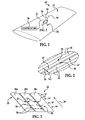
FIG. 1 is an illustration of a perspective view of composite structure being inspected by a portable gauge according to the disclosed embodiments. -
FIG. 2 is an illustration of an enlarged view of the area designated as "FIG. 2 " inFIG. 1 . -
FIG. 3 is an illustration of a perspective view of three adjacent strips of tape showing the 2-D profile of laser lines projected across adjacent tape edges. -
FIG. 4 is an illustration of a computer display screenshot graphically illustrating a tape gap measurement. -
FIG. 5 is a functional block diagram of the portable gauge and related control components. -
FIG. 6 is an illustration of a perspective view of one embodiment of the portable gauge. -
FIG. 7 is an illustration of a plan view of the portable gauge shown inFIG. 6 . -
FIG. 8 is an illustration of a perspective view of another embodiment the portable gauge that includes an on-board display screen. -
FIG. 9 is an illustration of a perspective view of a further embodiment of the portable gauge. -
FIG. 10 is an illustration of a perspective view showing how the portable gauge is initially aligned on a tape surface using a projected laser line. -
FIG. 11 is an illustration of a block diagram of electrical components of the portable gauge and a remote controller. -
FIG. 12 is an illustration of a flow diagram of a method of measuring tape gaps using the portable gauge. -
FIG. 13 is an illustration of a flow diagram of aircraft production and service methodology. -
FIG. 14 is an illustration of a block diagram of an aircraft. - Referring first to
FIGS. 1 and 2 , acomposite structure 24 is fabricated by laying up multiple, substantially parallel strips ofcomposite tape 26, sometimes also referred to herein as "tape strips", forming acomposite surface 22. In the illustrated example, thecomposite structure 24 comprises an aircraft wing, and thesurface 22 comprises the outer skin of the wing, however the disclosed embodiments may be used in connection with other composite structures that are formed from strips ofcomposite prepreg tape 26. The tape strips 26 may comprise groups of composite tows or materials other than composites. - As best seen in
FIG. 2 the parallel tape strips 26 are laid down in substantially edge-to-edge contact with each other. In one or more areas of thecomposite structure 24,gaps 28 may be present between adjacent ones of the tape strips 26. In the event that the width "W" of agap 28 exceeds a preselected tolerance, it may be necessary to rework the tape strips 26. For example, one or more of the tape strips 26 may be lifted, and repositioned in order to reduce the size of agap 28. Following this rework process, thesurface 22 is re-inspected to determine whether thegaps 28, if present, are within the desired range of tolerance. - In accordance with the disclosed embodiments, a
portable gauge 20 may be employed to perform the gap inspection process, and particularly to automatically measure and record the width "W" of thegaps 28 in the areas where thesurface 22 has been reworked. The inspection process may be carried out by a technician who moves thegauge 20 along thetape strip surface 22 in adirection 30 parallel to the tape strips 26 in each of the reworked areas. Thegauge 20 may include an arm and/or handle 34 that allows the technician to push or pull thegauge 20 along thesurface 22 continuously while thegauge 20 steers itself using anedge 27 of one of the tape strips 26 as a guide. Thegauge 20 performs successive rolling gap measurements at predetermined intervals using a measurement system that projectslaser lines 38 onto thesurface 22 which traverse across theedges 27 of adjacent tape strips 26. The impinginglaser lines 38 form a localized 2-D profile that is reflected, sensed and used by acontroller 36 to calculate gap measurements. Thecontroller 36 may be coupled to thegauge 20 either by wiring 23 or wirelessly. Thecontroller 36 may be stationary or may be carried by the technician as the continuous gap measurements are being automatically carried out. In the case of a large scalecomposite structure 24, it may be possible to carry out tape gap measurements using the disclosedportable gap gauge 20 in one area of thestructure 24 while composite tape strips 26 are being laid in another area of thestructure 24. - Referring to
FIG. 3 , thelaser lines 38 projected onto thetape surface 22 extend traversely across and down intogaps 28 on both sides of aparticular tape strip 26b, and are reflected as 2-D surface profiles representing thegaps 28. In the illustrated example, agap 28 is present betweenadjacent tape strips controller 36 which computes the width "W" ofgap 28 at successive positions "P" as thegauge 20 moves continuously in thedirection 30, corresponding to the direction that thetape 26 has been laid down. -
FIG. 4 illustrates adisplay 37 forming part of thecontroller 36 which may be used by a technician to view tape gap information, either in real time or after gap measurements are made and recorded. The right side of thedisplay 37 shows theply number 41,gap number 43 and theposition 45 along atape strip 26 where the gap is measured. Thetrigger interval 47 may also be selected, between thepositions 45 where gap measurements are made. The left side of thedisplay 37 shows agraph 44 in which a measured gap is displayed at 46 in two dimensions, corresponding to the 2-D surface profile along the laser lines 38. These two dimensions comprise the depth of the gap shown on theordinate 42, and its width and lateral position shown on theabscissa 40. -
FIG. 5 is a functional block diagram of theportable gauge 20 at the system level. Thegauge 20 includes aframe 48 provided with amovement system 59 that allows theframe 48 to move along thetape strip surface 22. Agap measurement system 57 measures thegap 28 between adjacent tape strips 26 (FIG. 2 ) at preselected intervals as theframe 48 moves along thesurface 22, continuously along the path of the tape strips 26. In other embodiments, thegap 28 may be measured continuously, rather than at intervals of time or distance traveled. Asteering system 55 provides active, automatic steering of the gauge as it moves along thetape surface 22. - Attention is now directed to
FIGS. 6 and 7 which illustrate additional details of theportable gauge 20. Thegauge 20 includes a generallyrectangular frame 48 having arear extension 39. Themovement system 59 comprises a pair ofwheels 50 mounted on theforward end 51 of theframe 48, and a trailing,steerable wheel 52. Thesteerable wheel 52 is mounted on asteering column 62 pivotally mounted on therear frame extension 39. Thesteering column 62 is pivotable about anaxis 53 that extends generally normal to thetape surface 22. Thewheels frame 48 to roll acrosssurface 22 during the tape gap measurement process. More or less than threewheels frame 48 for movement along thetape surface 22. Also, themovement system 59 may comprise any of various other types of mechanisms and structures that allow thegauge 20 to move along thetape surface 22. For example, and without limitation, themovement system 59 may comprise other forms of members, such as skids, skis or tracks that support theframe 48 on thetape strip surface 22 and allow thegauge 20 to traverse over simple or complex contours on thesurface 22. - The steering system 55 (
FIG. 5 ) includes anelectrical servo motor 56 mounted on therear frame extension 39. Theservo 56 rotates adisk 58 which is connected by asteering link 60 to asteering arm 61 on thesteering column 62. The rotational motion of thedisk 58 is transferred vialink 60 andarm 61 to rotate thesteering column 62 and therear wheel 52. A pair of 2-Dlaser line scanners frame 48. Each of thelaser line scanners laser line projector 67 and a corresponding 2-D non-contactoptical sensor 69 which sense the 2-D reflections of thelines 38 on thesurface 22. These sensed 2-D reflections are converted into electrical signals by theoptical sensors 69 which are used by thecontroller 36 to calculate the tape gaps. - As shown in
FIG. 7 , a position sensor in the form of arotary encoder 68 or similar device is coupled with one of theforward wheels 50 and functions to produce output signals that represent the linear position of thegauge 20 as it moves along the path of thetapes 26. Although not shown inFIGS. 6 or 7 , anarm 32 and/or handle 34 shown inFIG. 1 , may be attached to theframe 48 in order to allow a technician to roll thegauge 20 along thetape surface 22. In other embodiments, it is possible that movement of thegauge 20 may be self-propelled, driven by an on-board motor (not shown) -
FIG. 8 illustrates an alternate of the embodiment of theportable gauge 20 similar to that shown inFIGS. 6 and 7 except that alocal display screen 70 is mounted on theframe 48 which provide the technician with a display, similar to that shown inFIG. 4 , of thetape gap 28 being measured, along with the position of thegauge 20. -
FIG. 9 illustrates another embodiment of theportable gauge 20, similar to that shown inFIGS. 6-8 . In this embodiment, thelocal display screen 70 is mounted on asupport bracket 72 attached to theframe 48. Apush arm 32 is attached to thesupport 72 provides the technician with a means of moving thegauge 20 along thetape surface 22.Arm 32 may be coupled by a ball joint 74 to an upper arm portion 78 so that as the technician pushes against thearm 32, minimal lateral force is imparted to thegauge 20 which might affect steering. Alaser line generator 80 is mounted on theforward portion 52 of theframe 48 and is oriented to project aline 82 onto thetape surface 22.Line 82 may be used to align thegauge 20 with one of the tape strips 26 as shown inFIG. 10 , so that theedges 27 of the tape strips 26 are within the field-of-view of thelaser scanners - Attention is now directed to
FIG. 11 which broadly illustrates several of the electronic components of theportable gauge 20 and thecontroller 36. As previously discussed, theportable gauge 20 includes asteering servo motor 56 that controls therear wheel 52, a pair oflaser line scanners rotary encoder 68. Theportable gauge 20 may optionally include a joystick and/or anelectrical push button 84 that may be used to control steering or initiate a tape gap measurement cycle. Also, as previously discussed, theportable gauge 20 may include an optional on-board display screen 70 and alaser line generator 80. The on-board display screen 70 may display information similar to that which may be displayed on a touchscreen laptop computer 86 forming part of thecontroller 36 discussed below. - The
controller 36 broadly includes acomputer 86 which may comprise a personal computer in the form of touch screen laptop computer which is connected through a USB hub to theremote display screen 70. Thecomputer 86 generates and sends steering signals through theUSB hub 88 and a servoserial adapter 92 to thesteering servo motor 56. Signals generated by the joystick and/or pushbutton 84 are sent to thecomputer 86 through ajoystick control 94 and theUSB hub 88. The quadrature signals developed by therotary encoder 68 are delivered through a quadratureserial adapter 96 and theUSB hub 88 to thecomputer 86. Thecomputer 86 can be used to control thelaser line generator 80. Signals developed by theoptical sensors 69 forming part of the 2-Dlaser line scanners computer 86 via a 2-Dline sensor controller 90. It should be noted here that while thecontroller 36 is depicted as being separate from thegauge 20 in the disclosed embodiment, one or more components of thecontroller 36 may be mounted on-board thegauge 20 in other embodiments. - Attention is now directed to
FIG. 12 which illustrates the overall steps of a method of measuringtape gaps 28 using theportable gauge 20 previously described. Beginning at 100, thegauge 20 is placed on thetape surface 22 and at 102 thelaser line generator 80 may be used to align thegauge 20 the along tape strips 26. Next, atstep 104, the ply number and gap number are entered into thecomputer 86 using either the remote on-board screen 70 or the touch screen on thecomputer 86 which forms part of thecontroller 36. Next, at 106, the interval at which gap measurements are triggered is set and a specification range is selected at 108. The specification range selected at 108 establishes the criteria for classifying either the type or severity of the tape gap being measured. The specification range may correspond to pre-established manufacturing tolerances. At 110, theportable gauge 20 is moved along thetape surface 22 by a technician using the handheld arm 32 (FIG. 9 ) to push thegauge 20 forwardly, in the direction 30 (FIG. 3 ) that the tape strips 26 were initially laid down. Alternatively, as previously mentioned, thegauge 20 may be self-propelled. - At 112, the travel position of the
gauge 20 is sensed using the wheel drivenrotary encoder 68. At 114, the positions of theedges 27 of the tape strips 26 are sensed in the triggered intervals using thelaser line scanners gauge 20. At 117, the sensed tape edge information is output as data from themeasurement system 57 to thecontroller 36, and at 118, the sensed tape edge information is used to calculate thetape gap 28. The tape gap calculations are associated with the travel position of thegauge 20 atstep 120. The calculated tape gaps are stored at 122 along with associated travel positions of thegauge 20, and are displayed at 124 either in real time or in a playback, review mode. - Embodiments of the disclosure may find use in a variety of potential applications, particularly in the transportation industry, including for example, aerospace, marine and automotive applications, as well as in other industries where gaps between strips of material need to be measured. Thus, referring now to
FIGS. 13 and 14 , embodiments of the disclosure may be used in the context of an aircraft manufacturing andservice method 126 as shown inFigure 13 and anaircraft 128 as shown inFigure 14 . Aircraft applications of the disclosed embodiments may include, for example, without limitation, composite members such as fuselage skins, wing skins, control surfaces, hatches, floor panels, door panels, access panels and empennages, to name a few. During pre-production,exemplary method 126 may include specification anddesign 130 of theaircraft 126 andmaterial procurement 132. During production, component andsubassembly manufacturing 134 andsystem integration 136 of theaircraft 126 takes place. Thereafter, theaircraft 126 may go through certification anddelivery 138 in order to be placed inservice 140. While in service by a customer, theaircraft 126 is scheduled for routine maintenance and service 142 (which may also include modification, reconfiguration, refurbishment, and so on). - Each of the processes of
method 126 may be performed or carried out by a system integrator, a third party, and/or an operator (e.g., a customer). For the purposes of this description, a system integrator may include without limitation any number of aircraft manufacturers and major-system subcontractors; a third party may include without limitation any number of vendors, subcontractors, and suppliers; and an operator may be an airline, leasing company, military entity, service organization, and so on. - As shown in
FIG. 14 , theaircraft 128 produced byexemplary method 128 may include anairframe 144 with a plurality ofsystems 146 and an interior 148. Examples of high-level systems 146 include one or more of apropulsion system 150, anelectrical system 152, ahydraulic system 154, and anenvironmental system 156. Any number of other systems may be included. Although an aerospace example is shown, the principles of the disclosure may be applied to other industries, such as the marine and automotive industries. - Systems and methods embodied herein may be employed during any one or more of the stages of the production and
service method 126. For example, components or subassemblies corresponding toproduction process 134 may be fabricated or manufactured in a manner similar to components or subassemblies produced while theaircraft 128 is in service. Also, one or more apparatus embodiments, method embodiments, or a combination thereof may be utilized during the production stages 134 and 136, for example, by substantially expediting assembly of or reducing the cost of anaircraft 128. Similarly, one or more of apparatus embodiments, method embodiments, or a combination thereof may be utilized while theaircraft 128 is in service, for example and without limitation, to maintenance andservice 132. - Other method and apparatus embodiments are described in the clauses below.
- A9. A portable gauge for inspecting the surface of a composite structure formed from strips of composite tape, comprising: a measurement system for measuring a feature of the strips of the tape; and a movement system adapted to be placed on the surface of the structure for moving the measurement system along the surface.
- A10. The portable gauge of clause A9, wherein the feature is a gap between adjacent tape strips and measurement system includes: sensors for sensing the edges of adjacent ones of the tape strips and a computer coupled with the sensors for calculating the gap based on the location of the sensed edges.
- A11. The portable gauge of clause A10, wherein: the measurement system includes a pair of laser line projectors for projecting laser lines across the edges of the adjacent tape strips, and the sensors are positioned to sense 2-D reflections of the projected laser lines from the surface of the structure.
- A12. The portable gauge of clause A9, further comprising: a frame having the measurement system mounted thereon, and wherein the movement system includes members for supporting the frame on and movement along the surface of the structure.
- A13. The portable gauge of clause A12, wherein the movement system includes an active steering system for automatically steering the movement of the gauge along the tape strip surface.
- A14. The portable gauge of clause A9, wherein the measurement system includes a controller for automatically triggering acquiring and analyzing measurements of the feature.
- A15. The portable gauge of clause A12, further comprising: an arm adapted coupled with the frame and adapted to be engaged by an operator for moving the frame along the surface.
- A16. The portable gauge of clause A9, further comprising: an encoder for generating electrical signals related to the position of the measurement system along the length of the tape strips.
- A17. A gauge system for automatically measuring gaps between strips of composite tape forming an aircraft structure, comprising: a portable gauge movable along the tape strips, including - a frame, wheels on the frame for rolling the frame along the tape strips, including a pair of front wheels and a steerable rear wheel pivotally mounted on the frame behind the front wheels, a servo controlled motor on the frame for steering the rear wheel, linkage coupling the front wheel with the servo motor, a pair of laser scanners mounted on the frame, each of the laser scanners including a laser line projector for projecting a laser line across the edges of the tape strips, and a 2-D sensor for sensing a 2-D reflection of the projected laser lines, an on-board display mounted on the frame for displaying an image representing the tape gap, laser line generator for projecting a line onto the tape that may be used to initially align the frame with the tape strips, an arm adapted to be engaged by a human for pushing or pulling the gauge along the tape strips, and a laser device for aligning the gauge on the tape strips such that the edges of the tape strips are within the filed of view of the 2-D sensors; and a controller coupled with the gauge for delivering steering signals to the servo motor, for calculating the tape gaps at each of a plurality of locations along the tape strip and for associating the calculated tape gaps with the positions along the tape strips.
- A18. A method of measuring gaps between strips of composite tape forming an aircraft structure, comprising: placing a wheeled gauge on the surface of the structure; rolling the gauge along the surface of the structure; using a wheel on the gauge to drive a rotary encoder; using the rotary encoder to produce signals representing the position of the gauge in its movement along the surface; projecting a pair of laser lines onto the surface and respectively across two edges of a tape strip; sensing a 2-D reflection of the laser lines using a pair of non-contact sensors on the gauge, including sensing the edges of the tape strips; using a computer to calculate the gap between the tape strips at each of a plurality of positions on the surface of the structure; associating the calculated gaps with the positions of the gauge represented by the signals produced by the rotary encoder; generating steering gauge steering signals based on the edges sensed by the non-contact sensors; using a servo motor to steer one of the wheels on the gauge; and using the steering signals to control the servo motor.
- Although the embodiments of this disclosure have been described with respect to certain exemplary embodiments, it is to be understood that the specific embodiments are for purposes of illustration and not limitation, as other variations will occur to those of skill in the art.
Claims (15)
- A tape gap inspection gauge, comprising:a measurement system for measuring a gap between adjacent strips of the tape, including at least one non-contact sensor for sensing the edge of at least one of the tape strips; anda movement system for moving the measurement system along the surface of the tape strips.
- The gauge of claim 1, further comprising:a frame, andwherein the measurement system is mounted on the frame and the movement system includes a steering system on the frame for steering the movement of the frame along the tape strip surface.
- The gauge of claim 2, wherein:the movement system includes wheels supporting the frame for rolling movement along the tape strip surface, andthe steering system includes a servo motor coupled with at least one of the wheels for steering the wheel.
- The gauge of claim 3, further comprising:a controller for controlling the operation of the servo motor based on the location of an edge sensed by the non-contact sensor.
- The gauge of claim 1, wherein the measurement system includes two of the non-contact sensors for detecting the edges of at two adjacent tape strips.
- The gauge of claim 5, wherein:the measurement system includes a pair of laser line projectors for respectively projecting laser lines across the edges of adjacent ones of the tape strips, andthe non-contact sensors are operative for sensing a 2-D profile of the laser lines reflected from the tape strip surface.
- The gauge of claim 1, further comprising:a position sensor for sensing the position of the measurement system as the measurement system moves along the tape strip surface.
- The gauge of claim 1, further comprising:a controller for calculating the gap based on the sensed edge of the tape strip and for controlling the movement system.
- A method of measuring a gap between strips of composite tape forming a composite structure, comprising:placing a gauge on the surface of the structure;moving the gauge along the surface of the structure;using a measurement system on the gauge to measure gaps between the tape strips as the gauge is moved along the surface.
- The method of claim 9, wherein moving the gauge along the surface of the structure includes:rolling a frame along the surface, andautomatically steering the movement of the frame.
- The method of claim 9, wherein using the measurement system to measure the gaps includes:sensing the position of the edges of adjacent tape strips of the tape as the gauge is moved along the surface, andcalculating gaps between the adjacent strips based on the sensed position of the tape strip edges.
- The method of claim 11, further comprising:sensing the position of the gauge as the gauge moves along the surface; andcorrelating the calculated gaps with the recorded positions of the gauge.
- The method of claim 12, wherein sensing the position of the gauge is performed by:using a surface engaging wheel to drive a rotary encoder, andusing the rotary encoder to generate signals related to the position of the gauge on the surface.
- The method of claim 11, wherein sensing the position of the edges includes:projecting a line of light onto surface and the across the edges of adjacent strips of the tape, andsensing a 2-D reflection of the line of light.
- The method of claim 11, wherein moving the gauge along the surface includes automatically steering the gauge based on the sensed position of the tape strip edges.
Applications Claiming Priority (1)
| Application Number | Priority Date | Filing Date | Title |
|---|---|---|---|
| US13/118,410 US8514412B2 (en) | 2011-05-28 | 2011-05-28 | Portable gauge and method for measuring tape gaps |
Publications (2)
| Publication Number | Publication Date |
|---|---|
| EP2530427A1 true EP2530427A1 (en) | 2012-12-05 |
| EP2530427B1 EP2530427B1 (en) | 2018-03-21 |
Family
ID=46420032
Family Applications (1)
| Application Number | Title | Priority Date | Filing Date |
|---|---|---|---|
| EP12275068.0A Not-in-force EP2530427B1 (en) | 2011-05-28 | 2012-05-14 | Portable gauge and method for measuring tape gaps |
Country Status (5)
| Country | Link |
|---|---|
| US (1) | US8514412B2 (en) |
| EP (1) | EP2530427B1 (en) |
| JP (1) | JP6128752B2 (en) |
| CA (1) | CA2773821C (en) |
| ES (1) | ES2674146T3 (en) |
Families Citing this family (4)
| Publication number | Priority date | Publication date | Assignee | Title |
|---|---|---|---|---|
| US9855733B2 (en) * | 2015-03-02 | 2018-01-02 | The Boeing Company | Method for achieving low porosity in composite laminates |
| US10197392B2 (en) * | 2015-06-23 | 2019-02-05 | The Boeing Company | Automated resin ridge reduction system |
| GB2564709B (en) * | 2017-07-21 | 2020-02-12 | Magma Global Ltd | Composite tape tracking |
| JP7822749B2 (en) * | 2020-11-18 | 2026-03-03 | ザ・ボーイング・カンパニー | Dynamic mapping for moving parts within a manufacturing environment |
Citations (2)
| Publication number | Priority date | Publication date | Assignee | Title |
|---|---|---|---|---|
| WO2005103608A1 (en) * | 2004-04-21 | 2005-11-03 | Remote Vision Solutions Pty Ltd | Continuous surface deformation measurement |
| US20070271064A1 (en) * | 2006-05-16 | 2007-11-22 | The Boeing Company | System and method for identifying a feature of a workpiece |
Family Cites Families (18)
| Publication number | Priority date | Publication date | Assignee | Title |
|---|---|---|---|---|
| US4666303A (en) * | 1983-07-11 | 1987-05-19 | Diffracto Ltd. | Electro-optical gap and flushness sensors |
| JPS63175854U (en) * | 1987-05-06 | 1988-11-15 | ||
| JPH071235B2 (en) * | 1987-07-01 | 1995-01-11 | 富士写真フイルム株式会社 | Bonding inspection device |
| US5052799A (en) * | 1989-07-17 | 1991-10-01 | Thurman Sasser | Object orienting systems and systems and processes relating thereto |
| US5120976A (en) * | 1990-07-25 | 1992-06-09 | The Boeing Company | Strip lay-up verification system with width and centerline skew determination |
| JPH0727511A (en) * | 1993-07-08 | 1995-01-27 | Sekisui Chem Co Ltd | Weld line position detection method |
| US5562788A (en) | 1994-09-20 | 1996-10-08 | The Boeing Company | Composite material laser flaw detection |
| JPH10260141A (en) * | 1997-03-18 | 1998-09-29 | Hitachi Denshi Ltd | Defect inspection equipment |
| JP2000283731A (en) * | 1999-03-30 | 2000-10-13 | Osaka Gas Co Ltd | Weld line position measuring method, weld line position measuring device, and traveling body automatically following weld line |
| JP2003004642A (en) * | 2001-06-19 | 2003-01-08 | Ilc:Kk | Floor material deterioration observation robot and floor material management system using it |
| CA2412815A1 (en) * | 2002-11-27 | 2004-05-27 | Martin Deschambault | Mobile and modular robot platform with several means of locomotion for making advanced movements in three dimensions |
| JP3728511B2 (en) * | 2003-07-07 | 2005-12-21 | 国立大学法人名古屋大学 | Mobile three-dimensional structure measuring device |
| US7289656B2 (en) | 2003-12-02 | 2007-10-30 | The Boeing Company | Systems and methods for determining inconsistency characteristics of a composite structure |
| US7253908B2 (en) * | 2004-07-22 | 2007-08-07 | The Boeing Company | Non-destructive inspection using laser profiling and associated method |
| US7978328B2 (en) * | 2006-03-28 | 2011-07-12 | The Boeing Company | Vision inspection system device and method |
| US20070277919A1 (en) | 2006-05-16 | 2007-12-06 | The Boeing Company | Systems and methods for monitoring automated composite manufacturing processes |
| US7495758B2 (en) * | 2006-09-06 | 2009-02-24 | Theo Boeing Company | Apparatus and methods for two-dimensional and three-dimensional inspection of a workpiece |
| US7876458B2 (en) * | 2007-02-01 | 2011-01-25 | Michael Rogler Kildevaeld | Highlighting gaps in a surface |
-
2011
- 2011-05-28 US US13/118,410 patent/US8514412B2/en not_active Expired - Fee Related
-
2012
- 2012-04-10 CA CA2773821A patent/CA2773821C/en not_active Expired - Fee Related
- 2012-05-14 ES ES12275068.0T patent/ES2674146T3/en active Active
- 2012-05-14 EP EP12275068.0A patent/EP2530427B1/en not_active Not-in-force
- 2012-05-18 JP JP2012114986A patent/JP6128752B2/en active Active
Patent Citations (2)
| Publication number | Priority date | Publication date | Assignee | Title |
|---|---|---|---|---|
| WO2005103608A1 (en) * | 2004-04-21 | 2005-11-03 | Remote Vision Solutions Pty Ltd | Continuous surface deformation measurement |
| US20070271064A1 (en) * | 2006-05-16 | 2007-11-22 | The Boeing Company | System and method for identifying a feature of a workpiece |
Also Published As
| Publication number | Publication date |
|---|---|
| US20120300221A1 (en) | 2012-11-29 |
| JP6128752B2 (en) | 2017-05-17 |
| CA2773821C (en) | 2016-07-26 |
| ES2674146T3 (en) | 2018-06-27 |
| JP2012247414A (en) | 2012-12-13 |
| US8514412B2 (en) | 2013-08-20 |
| EP2530427B1 (en) | 2018-03-21 |
| CA2773821A1 (en) | 2012-11-28 |
Similar Documents
| Publication | Publication Date | Title |
|---|---|---|
| US11485018B2 (en) | Robotic end effector system with surface tracking and methods for use | |
| US20200230899A1 (en) | In-situ monitoring of thermoformable composites | |
| US8568545B2 (en) | Automated material removal in composite structures | |
| AU2006279900B2 (en) | Systems and methods for in-process vision inspection for automated machines | |
| EP2952890B1 (en) | Automated scanning method for non-destructive inspection of curved cylinder-like workpieces | |
| US8524020B2 (en) | Method of restoring a composite airframe | |
| EP1857260B1 (en) | Systems and methods for monitoring automated composite fabrication processes | |
| US10899089B2 (en) | Automated fiber placement end effector with laminar gas cooling jet and infrared image processor for in-situ inspection | |
| CN107436590B (en) | Inspection of a tow laid by a robot | |
| US12605842B2 (en) | Robot tracking device | |
| US20190331620A1 (en) | Methods for Inspecting Structures Having Non-Planar Surfaces Using Location Alignment Feedback | |
| CA2773821C (en) | Portable gauge and method for measuring tape gaps | |
| US20120328159A9 (en) | System and method for determining cumulative tow gap width | |
| JP2010540901A (en) | Method and apparatus for measuring the width of a composite tape | |
| EP4071467B1 (en) | Ultrasound inspection system and method | |
| JP2012247414A5 (en) | ||
| EP3552809B1 (en) | Automated fiber placement end effector with laminar gas cooling jet and infrared image processor for in-situ inspection | |
| JP2022080860A (en) | Dynamic indexing for moving parts in fabrication environment | |
| US20230341342A1 (en) | In-situ monitoring of thermoformable composites | |
| CN116413053A (en) | On-line consistency detection and analysis method for production line tooling equipment | |
| EP4494855A1 (en) | Composite lamination system and methods | |
| EP4000888B1 (en) | Continuously moving line for making composite laminate parts | |
| NL2020882B1 (en) | Automated fiber placement end effector with laminar gas cooling jet and infrared image processor for in-situ inspection |
Legal Events
| Date | Code | Title | Description |
|---|---|---|---|
| PUAI | Public reference made under article 153(3) epc to a published international application that has entered the european phase |
Free format text: ORIGINAL CODE: 0009012 |
|
| 17P | Request for examination filed |
Effective date: 20120514 |
|
| AK | Designated contracting states |
Kind code of ref document: A1 Designated state(s): AL AT BE BG CH CY CZ DE DK EE ES FI FR GB GR HR HU IE IS IT LI LT LU LV MC MK MT NL NO PL PT RO RS SE SI SK SM TR |
|
| AX | Request for extension of the european patent |
Extension state: BA ME |
|
| GRAP | Despatch of communication of intention to grant a patent |
Free format text: ORIGINAL CODE: EPIDOSNIGR1 |
|
| INTG | Intention to grant announced |
Effective date: 20171002 |
|
| GRAS | Grant fee paid |
Free format text: ORIGINAL CODE: EPIDOSNIGR3 |
|
| GRAA | (expected) grant |
Free format text: ORIGINAL CODE: 0009210 |
|
| AK | Designated contracting states |
Kind code of ref document: B1 Designated state(s): AL AT BE BG CH CY CZ DE DK EE ES FI FR GB GR HR HU IE IS IT LI LT LU LV MC MK MT NL NO PL PT RO RS SE SI SK SM TR |
|
| REG | Reference to a national code |
Ref country code: GB Ref legal event code: FG4D |
|
| REG | Reference to a national code |
Ref country code: CH Ref legal event code: EP |
|
| REG | Reference to a national code |
Ref country code: AT Ref legal event code: REF Ref document number: 981592 Country of ref document: AT Kind code of ref document: T Effective date: 20180415 |
|
| REG | Reference to a national code |
Ref country code: IE Ref legal event code: FG4D |
|
| REG | Reference to a national code |
Ref country code: DE Ref legal event code: R096 Ref document number: 602012044149 Country of ref document: DE |
|
| REG | Reference to a national code |
Ref country code: FR Ref legal event code: PLFP Year of fee payment: 7 |
|
| REG | Reference to a national code |
Ref country code: ES Ref legal event code: FG2A Ref document number: 2674146 Country of ref document: ES Kind code of ref document: T3 Effective date: 20180627 |
|
| REG | Reference to a national code |
Ref country code: NL Ref legal event code: MP Effective date: 20180321 |
|
| PG25 | Lapsed in a contracting state [announced via postgrant information from national office to epo] |
Ref country code: LT Free format text: LAPSE BECAUSE OF FAILURE TO SUBMIT A TRANSLATION OF THE DESCRIPTION OR TO PAY THE FEE WITHIN THE PRESCRIBED TIME-LIMIT Effective date: 20180321 Ref country code: CY Free format text: LAPSE BECAUSE OF FAILURE TO SUBMIT A TRANSLATION OF THE DESCRIPTION OR TO PAY THE FEE WITHIN THE PRESCRIBED TIME-LIMIT Effective date: 20180321 Ref country code: FI Free format text: LAPSE BECAUSE OF FAILURE TO SUBMIT A TRANSLATION OF THE DESCRIPTION OR TO PAY THE FEE WITHIN THE PRESCRIBED TIME-LIMIT Effective date: 20180321 Ref country code: NO Free format text: LAPSE BECAUSE OF FAILURE TO SUBMIT A TRANSLATION OF THE DESCRIPTION OR TO PAY THE FEE WITHIN THE PRESCRIBED TIME-LIMIT Effective date: 20180621 Ref country code: HR Free format text: LAPSE BECAUSE OF FAILURE TO SUBMIT A TRANSLATION OF THE DESCRIPTION OR TO PAY THE FEE WITHIN THE PRESCRIBED TIME-LIMIT Effective date: 20180321 |
|
| REG | Reference to a national code |
Ref country code: LT Ref legal event code: MG4D |
|
| REG | Reference to a national code |
Ref country code: AT Ref legal event code: MK05 Ref document number: 981592 Country of ref document: AT Kind code of ref document: T Effective date: 20180321 |
|
| PG25 | Lapsed in a contracting state [announced via postgrant information from national office to epo] |
Ref country code: LV Free format text: LAPSE BECAUSE OF FAILURE TO SUBMIT A TRANSLATION OF THE DESCRIPTION OR TO PAY THE FEE WITHIN THE PRESCRIBED TIME-LIMIT Effective date: 20180321 Ref country code: SE Free format text: LAPSE BECAUSE OF FAILURE TO SUBMIT A TRANSLATION OF THE DESCRIPTION OR TO PAY THE FEE WITHIN THE PRESCRIBED TIME-LIMIT Effective date: 20180321 Ref country code: RS Free format text: LAPSE BECAUSE OF FAILURE TO SUBMIT A TRANSLATION OF THE DESCRIPTION OR TO PAY THE FEE WITHIN THE PRESCRIBED TIME-LIMIT Effective date: 20180321 Ref country code: BG Free format text: LAPSE BECAUSE OF FAILURE TO SUBMIT A TRANSLATION OF THE DESCRIPTION OR TO PAY THE FEE WITHIN THE PRESCRIBED TIME-LIMIT Effective date: 20180621 Ref country code: GR Free format text: LAPSE BECAUSE OF FAILURE TO SUBMIT A TRANSLATION OF THE DESCRIPTION OR TO PAY THE FEE WITHIN THE PRESCRIBED TIME-LIMIT Effective date: 20180622 |
|
| PG25 | Lapsed in a contracting state [announced via postgrant information from national office to epo] |
Ref country code: RO Free format text: LAPSE BECAUSE OF FAILURE TO SUBMIT A TRANSLATION OF THE DESCRIPTION OR TO PAY THE FEE WITHIN THE PRESCRIBED TIME-LIMIT Effective date: 20180321 Ref country code: NL Free format text: LAPSE BECAUSE OF FAILURE TO SUBMIT A TRANSLATION OF THE DESCRIPTION OR TO PAY THE FEE WITHIN THE PRESCRIBED TIME-LIMIT Effective date: 20180321 Ref country code: EE Free format text: LAPSE BECAUSE OF FAILURE TO SUBMIT A TRANSLATION OF THE DESCRIPTION OR TO PAY THE FEE WITHIN THE PRESCRIBED TIME-LIMIT Effective date: 20180321 Ref country code: PL Free format text: LAPSE BECAUSE OF FAILURE TO SUBMIT A TRANSLATION OF THE DESCRIPTION OR TO PAY THE FEE WITHIN THE PRESCRIBED TIME-LIMIT Effective date: 20180321 Ref country code: IT Free format text: LAPSE BECAUSE OF FAILURE TO SUBMIT A TRANSLATION OF THE DESCRIPTION OR TO PAY THE FEE WITHIN THE PRESCRIBED TIME-LIMIT Effective date: 20180321 Ref country code: AL Free format text: LAPSE BECAUSE OF FAILURE TO SUBMIT A TRANSLATION OF THE DESCRIPTION OR TO PAY THE FEE WITHIN THE PRESCRIBED TIME-LIMIT Effective date: 20180321 |
|
| PG25 | Lapsed in a contracting state [announced via postgrant information from national office to epo] |
Ref country code: SK Free format text: LAPSE BECAUSE OF FAILURE TO SUBMIT A TRANSLATION OF THE DESCRIPTION OR TO PAY THE FEE WITHIN THE PRESCRIBED TIME-LIMIT Effective date: 20180321 Ref country code: SM Free format text: LAPSE BECAUSE OF FAILURE TO SUBMIT A TRANSLATION OF THE DESCRIPTION OR TO PAY THE FEE WITHIN THE PRESCRIBED TIME-LIMIT Effective date: 20180321 Ref country code: AT Free format text: LAPSE BECAUSE OF FAILURE TO SUBMIT A TRANSLATION OF THE DESCRIPTION OR TO PAY THE FEE WITHIN THE PRESCRIBED TIME-LIMIT Effective date: 20180321 Ref country code: CZ Free format text: LAPSE BECAUSE OF FAILURE TO SUBMIT A TRANSLATION OF THE DESCRIPTION OR TO PAY THE FEE WITHIN THE PRESCRIBED TIME-LIMIT Effective date: 20180321 |
|
| REG | Reference to a national code |
Ref country code: CH Ref legal event code: PL |
|
| PG25 | Lapsed in a contracting state [announced via postgrant information from national office to epo] |
Ref country code: PT Free format text: LAPSE BECAUSE OF FAILURE TO SUBMIT A TRANSLATION OF THE DESCRIPTION OR TO PAY THE FEE WITHIN THE PRESCRIBED TIME-LIMIT Effective date: 20180723 |
|
| REG | Reference to a national code |
Ref country code: DE Ref legal event code: R097 Ref document number: 602012044149 Country of ref document: DE |
|
| PLBE | No opposition filed within time limit |
Free format text: ORIGINAL CODE: 0009261 |
|
| STAA | Information on the status of an ep patent application or granted ep patent |
Free format text: STATUS: NO OPPOSITION FILED WITHIN TIME LIMIT |
|
| REG | Reference to a national code |
Ref country code: BE Ref legal event code: MM Effective date: 20180531 |
|
| PG25 | Lapsed in a contracting state [announced via postgrant information from national office to epo] |
Ref country code: MC Free format text: LAPSE BECAUSE OF FAILURE TO SUBMIT A TRANSLATION OF THE DESCRIPTION OR TO PAY THE FEE WITHIN THE PRESCRIBED TIME-LIMIT Effective date: 20180321 Ref country code: DK Free format text: LAPSE BECAUSE OF FAILURE TO SUBMIT A TRANSLATION OF THE DESCRIPTION OR TO PAY THE FEE WITHIN THE PRESCRIBED TIME-LIMIT Effective date: 20180321 |
|
| REG | Reference to a national code |
Ref country code: IE Ref legal event code: MM4A |
|
| 26N | No opposition filed |
Effective date: 20190102 |
|
| PG25 | Lapsed in a contracting state [announced via postgrant information from national office to epo] |
Ref country code: LI Free format text: LAPSE BECAUSE OF NON-PAYMENT OF DUE FEES Effective date: 20180531 Ref country code: CH Free format text: LAPSE BECAUSE OF NON-PAYMENT OF DUE FEES Effective date: 20180531 |
|
| PG25 | Lapsed in a contracting state [announced via postgrant information from national office to epo] |
Ref country code: LU Free format text: LAPSE BECAUSE OF NON-PAYMENT OF DUE FEES Effective date: 20180514 |
|
| PG25 | Lapsed in a contracting state [announced via postgrant information from national office to epo] |
Ref country code: IE Free format text: LAPSE BECAUSE OF NON-PAYMENT OF DUE FEES Effective date: 20180514 |
|
| PG25 | Lapsed in a contracting state [announced via postgrant information from national office to epo] |
Ref country code: BE Free format text: LAPSE BECAUSE OF NON-PAYMENT OF DUE FEES Effective date: 20180531 Ref country code: SI Free format text: LAPSE BECAUSE OF FAILURE TO SUBMIT A TRANSLATION OF THE DESCRIPTION OR TO PAY THE FEE WITHIN THE PRESCRIBED TIME-LIMIT Effective date: 20180321 |
|
| REG | Reference to a national code |
Ref country code: DE Ref legal event code: R082 Ref document number: 602012044149 Country of ref document: DE Representative=s name: MAIER, LL.M., MICHAEL C., DE Ref country code: DE Ref legal event code: R082 Ref document number: 602012044149 Country of ref document: DE Representative=s name: BOULT WADE TENNANT LLP, DE |
|
| PG25 | Lapsed in a contracting state [announced via postgrant information from national office to epo] |
Ref country code: MT Free format text: LAPSE BECAUSE OF NON-PAYMENT OF DUE FEES Effective date: 20180514 |
|
| REG | Reference to a national code |
Ref country code: DE Ref legal event code: R082 Ref document number: 602012044149 Country of ref document: DE Representative=s name: BOULT WADE TENNANT LLP, DE |
|
| PG25 | Lapsed in a contracting state [announced via postgrant information from national office to epo] |
Ref country code: TR Free format text: LAPSE BECAUSE OF FAILURE TO SUBMIT A TRANSLATION OF THE DESCRIPTION OR TO PAY THE FEE WITHIN THE PRESCRIBED TIME-LIMIT Effective date: 20180321 |
|
| PG25 | Lapsed in a contracting state [announced via postgrant information from national office to epo] |
Ref country code: HU Free format text: LAPSE BECAUSE OF FAILURE TO SUBMIT A TRANSLATION OF THE DESCRIPTION OR TO PAY THE FEE WITHIN THE PRESCRIBED TIME-LIMIT; INVALID AB INITIO Effective date: 20120514 |
|
| PG25 | Lapsed in a contracting state [announced via postgrant information from national office to epo] |
Ref country code: MK Free format text: LAPSE BECAUSE OF NON-PAYMENT OF DUE FEES Effective date: 20180321 |
|
| PG25 | Lapsed in a contracting state [announced via postgrant information from national office to epo] |
Ref country code: IS Free format text: LAPSE BECAUSE OF FAILURE TO SUBMIT A TRANSLATION OF THE DESCRIPTION OR TO PAY THE FEE WITHIN THE PRESCRIBED TIME-LIMIT Effective date: 20180721 |
|
| PGFP | Annual fee paid to national office [announced via postgrant information from national office to epo] |
Ref country code: FR Payment date: 20200525 Year of fee payment: 9 Ref country code: ES Payment date: 20200601 Year of fee payment: 9 Ref country code: DE Payment date: 20200528 Year of fee payment: 9 |
|
| PGFP | Annual fee paid to national office [announced via postgrant information from national office to epo] |
Ref country code: GB Payment date: 20200527 Year of fee payment: 9 |
|
| REG | Reference to a national code |
Ref country code: DE Ref legal event code: R119 Ref document number: 602012044149 Country of ref document: DE |
|
| GBPC | Gb: european patent ceased through non-payment of renewal fee |
Effective date: 20210514 |
|
| PG25 | Lapsed in a contracting state [announced via postgrant information from national office to epo] |
Ref country code: GB Free format text: LAPSE BECAUSE OF NON-PAYMENT OF DUE FEES Effective date: 20210514 Ref country code: DE Free format text: LAPSE BECAUSE OF NON-PAYMENT OF DUE FEES Effective date: 20211201 |
|
| PG25 | Lapsed in a contracting state [announced via postgrant information from national office to epo] |
Ref country code: FR Free format text: LAPSE BECAUSE OF NON-PAYMENT OF DUE FEES Effective date: 20210531 |
|
| REG | Reference to a national code |
Ref country code: ES Ref legal event code: FD2A Effective date: 20220801 |
|
| PG25 | Lapsed in a contracting state [announced via postgrant information from national office to epo] |
Ref country code: ES Free format text: LAPSE BECAUSE OF NON-PAYMENT OF DUE FEES Effective date: 20210515 |