EP2530244A2 - A turbine blade or vane segment and a method of cooling a gap between these segments - Google Patents
A turbine blade or vane segment and a method of cooling a gap between these segments Download PDFInfo
- Publication number
- EP2530244A2 EP2530244A2 EP12169886A EP12169886A EP2530244A2 EP 2530244 A2 EP2530244 A2 EP 2530244A2 EP 12169886 A EP12169886 A EP 12169886A EP 12169886 A EP12169886 A EP 12169886A EP 2530244 A2 EP2530244 A2 EP 2530244A2
- Authority
- EP
- European Patent Office
- Prior art keywords
- substantially axially
- pressure
- side edges
- extending
- extending side
- Prior art date
- Legal status (The legal status is an assumption and is not a legal conclusion. Google has not performed a legal analysis and makes no representation as to the accuracy of the status listed.)
- Granted
Links
Images


Classifications
-
- F—MECHANICAL ENGINEERING; LIGHTING; HEATING; WEAPONS; BLASTING
- F01—MACHINES OR ENGINES IN GENERAL; ENGINE PLANTS IN GENERAL; STEAM ENGINES
- F01D—NON-POSITIVE DISPLACEMENT MACHINES OR ENGINES, e.g. STEAM TURBINES
- F01D5/00—Blades; Blade-carrying members; Heating, heat-insulating, cooling or antivibration means on the blades or the members
- F01D5/12—Blades
- F01D5/14—Form or construction
- F01D5/18—Hollow blades, i.e. blades with cooling or heating channels or cavities; Heating, heat-insulating or cooling means on blades
- F01D5/187—Convection cooling
-
- F—MECHANICAL ENGINEERING; LIGHTING; HEATING; WEAPONS; BLASTING
- F01—MACHINES OR ENGINES IN GENERAL; ENGINE PLANTS IN GENERAL; STEAM ENGINES
- F01D—NON-POSITIVE DISPLACEMENT MACHINES OR ENGINES, e.g. STEAM TURBINES
- F01D11/00—Preventing or minimising internal leakage of working-fluid, e.g. between stages
- F01D11/005—Sealing means between non relatively rotating elements
- F01D11/006—Sealing the gap between rotor blades or blades and rotor
-
- F—MECHANICAL ENGINEERING; LIGHTING; HEATING; WEAPONS; BLASTING
- F01—MACHINES OR ENGINES IN GENERAL; ENGINE PLANTS IN GENERAL; STEAM ENGINES
- F01D—NON-POSITIVE DISPLACEMENT MACHINES OR ENGINES, e.g. STEAM TURBINES
- F01D9/00—Stators
- F01D9/06—Fluid supply conduits to nozzles or the like
- F01D9/065—Fluid supply or removal conduits traversing the working fluid flow, e.g. for lubrication-, cooling-, or sealing fluids
-
- F—MECHANICAL ENGINEERING; LIGHTING; HEATING; WEAPONS; BLASTING
- F05—INDEXING SCHEMES RELATING TO ENGINES OR PUMPS IN VARIOUS SUBCLASSES OF CLASSES F01-F04
- F05D—INDEXING SCHEME FOR ASPECTS RELATING TO NON-POSITIVE-DISPLACEMENT MACHINES OR ENGINES, GAS-TURBINES OR JET-PROPULSION PLANTS
- F05D2240/00—Components
- F05D2240/80—Platforms for stationary or moving blades
- F05D2240/81—Cooled platforms
-
- F—MECHANICAL ENGINEERING; LIGHTING; HEATING; WEAPONS; BLASTING
- F05—INDEXING SCHEMES RELATING TO ENGINES OR PUMPS IN VARIOUS SUBCLASSES OF CLASSES F01-F04
- F05D—INDEXING SCHEME FOR ASPECTS RELATING TO NON-POSITIVE-DISPLACEMENT MACHINES OR ENGINES, GAS-TURBINES OR JET-PROPULSION PLANTS
- F05D2270/00—Control
- F05D2270/30—Control parameters, e.g. input parameters
- F05D2270/301—Pressure
- F05D2270/3015—Pressure differential pressure
-
- Y—GENERAL TAGGING OF NEW TECHNOLOGICAL DEVELOPMENTS; GENERAL TAGGING OF CROSS-SECTIONAL TECHNOLOGIES SPANNING OVER SEVERAL SECTIONS OF THE IPC; TECHNICAL SUBJECTS COVERED BY FORMER USPC CROSS-REFERENCE ART COLLECTIONS [XRACs] AND DIGESTS
- Y02—TECHNOLOGIES OR APPLICATIONS FOR MITIGATION OR ADAPTATION AGAINST CLIMATE CHANGE
- Y02T—CLIMATE CHANGE MITIGATION TECHNOLOGIES RELATED TO TRANSPORTATION
- Y02T50/00—Aeronautics or air transport
- Y02T50/60—Efficient propulsion technologies, e.g. for aircraft
Definitions
- the present invention relates generally to turbomachines and more particularly to vane and blade assemblies utilized in the high pressure turbine section of gas turbine engines.
- Certain components of the gas turbine engine for example, stationary vane segments of a turbine stator assembly which closely surround the turbine rotor and which define the outer boundary for the hot combustion gases flowing through the turbine, are directly exposed to the heated stream of combustion gases.
- the vane segments typically incorporate one, two or more individual vanes or airfoils extending between inner and outer bands or shrouds.
- a turbine vane segment comprising at least one airfoil extending radially outwardly from a radially inner band, the radially inner band formed with substantially axially-extending side edges; the at least one airfoil formed with a leading edge, a trailing edge, a pressure side and a suction side; the pressure side facing one of the substantially axially-extending edges and the leading edge located proximate to the one of the substantially axially-extending edges; and a plurality of cooling passages formed in the radially inner band in fluid communication with a source of cooling air and exiting the inner band via a plurality of exit holes in the one of the substantially axially-extending edges, the plurality of exit holes confined to a region along the one of the substantially axially-extending side edges where static pressure P S along the one of the substantially axially-extending side edges lies in a pressure range, ⁇ P D , substantially between the stage inlet total pressure, PT, and a pressure
- each vane segment includes at least one airfoil extending between radially inner and outer bands, at least the radially inner band formed with substantially axially-extending side edges; the airfoil formed with a leading edge, a trailing edge, a pressure side and a suction side, and an internal cooling plenum; the pressure side facing one of the substantially axially-extending side edges and the leading edge located proximate to the one of the substantially axially-extending side edges; the method comprising identifying a length portion of the one of the substantially axially-extending side edges of the radially inner or outer bands where static pressure P S along the one of the substantially axially-extending side edges lies in a pressure range, ⁇ P D , substantially between the total stage inlet pressure P T and a pressure that is substantially about 1.5 times the dynamic pressure range below the total stage inlet pressure.
- a turbine vane segment 10 includes a radially outer band or shroud 12 and a radially inner band or shroud 14. Between the inner and outer bands, there is a pair of airfoils 16 and 18 (a two-airfoil segment is sometimes referred to as a "doublet"). Other vane segments may have one or more than two individual airfoils, and the invention here is not limited to any particular number of airfoils in the vane segment.
- the airfoils 16 and 18 are substantially identical with the exception of their orientation relative to the inner and outer bands. Accordingly, and with reference especially to Fig. 3 , it may be seen that the blade or airfoil 16 has a leading edge 20, a trailing edge 22, a pressure side 24 and a suction side 26.
- the individual arcuate vane segments 10 are arranged in a stationary, annular array about the turbine rotor as is well understood in the art.
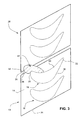
- Figs. 2 and 3 show a pair of vane segments 10 and 28 as they would appear in an installed state, with a gap 30 extending substantially axially therebetween.
- the substantially axially-extending side edges 32 and 34 of the segment 10 are referred to as slashfaces.
- slashface 32 of the segment 10 and slashface 36 of the segment 28 are opposed to each other and define the gap 30, also referred to herein as the "chute" or "chute region”.
- the leading edge 20 of the airfoil 16 lies in relatively close proximity to the slashface 32.
- cooling passages may be formed to exit from the slashface 32 of vane segment 10 and/or the slashface 36 of the adjacent vane segment 28 as described further herein.
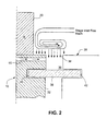
- the chute 30 can be seen clearly between the opposed slashfaces 32, 36 of respective segments 10, 28, and the radial depth of the chute 30 is defined by the location of an intersegment seal 38 ( Fig. 2 ) seated in respective slots 40, 42 and extending axially along the adjacent slashfaces 32, 36.
- the chute 30 is supplied with cooling air that is focused or concentrated only on the high pressure region 44 of the slashface 32.
- FIG. 3 where the high pressure region 44 is schematically shown at the leading edge 20, and extending partially along the pressure side 24 of the airfoil 16, and with a fairly well-defmed high pressure area along the slashface 32.
- the range of high pressures determined to be potentially damaging to the slashface 32 and hence the entire vane segment 10, is within certain boundaries along the slashface as defmed below.
- identification of the high pressure region along the slashface 32 to be cooled can be determined by calculating total pressure P T and Mach number M at the inlet to the turbine stage; static pressure P S along the slashface 32; and dynamic pressure ⁇ P D which is defmed as P T -P S at the stage inlet, which can be calculated by standard isentropic flow equations as a function of stage inlet total pressure and stage inlet Mach number. As can be seen in Fig.
- the highest pressures along the slashface 32 lie in a region where static pressure P S along said one of said substantially axially-extending side edges lies in a pressure range ⁇ P substantially between the stage inlet total pressure P T and a pressure that is substantially about 1.5 times the dynamic pressure range ⁇ P D below the stage inlet total pressure.
- a plurality of cooling passages 46, 48, 50, 52 and 54 extend through the inner band 14 of either airfoil adjacent to the chute gap from an internal plenum provided within the airfoil 16 to the slashface 32.
- cooling passages 47, 49, 51 and 53 could extend to the chute 30 from a plenum (not shown) in airfoil 56 in the adjacent vane segment 28.
- cooling air could be supplied from both sets of cooling passages, or from any other available source.
- the hot combustion gas in the chute 30 is partially prevented from entering the chute by mixing the cooling air with the combustion gas, and the slashface 32 (particularly in the high pressure region 44) is exposed to cooler air.
- the cooling air flowing through the passages 46, 48, 50, 52 and 54 has a further beneficial effect in that they cool the inner band 14 by convective cooling.
- the invention is not limited to utilization along a single edge of the inner band, but is also applicable to either or both of inner and outer bands.
- the invention has applicability not only to stationary vane segments but also to rotating buckets on rotor wheels located between the vane stages.
Landscapes
- Engineering & Computer Science (AREA)
- Mechanical Engineering (AREA)
- General Engineering & Computer Science (AREA)
- Physics & Mathematics (AREA)
- Fluid Mechanics (AREA)
- Turbine Rotor Nozzle Sealing (AREA)
Abstract
Description
- The present invention relates generally to turbomachines and more particularly to vane and blade assemblies utilized in the high pressure turbine section of gas turbine engines.
- It is desirable to operate a gas turbine engine at high temperatures most efficient for generating and extracting energy from the combustion gases. Certain components of the gas turbine engine, for example, stationary vane segments of a turbine stator assembly which closely surround the turbine rotor and which define the outer boundary for the hot combustion gases flowing through the turbine, are directly exposed to the heated stream of combustion gases. The vane segments typically incorporate one, two or more individual vanes or airfoils extending between inner and outer bands or shrouds.
- It has been determined that there is the potential for significant increases in temperature on the sidewalls of the vane segments, due to a lack of cooling air sweeping over the intersegment gap between two adjacent vane segments. Instead of cooling air, hot combustion gas is forced into the "chute" above the intersegment seal in the gap between adjacent vane segments. The combustion gas heats the edges of the vane segment inner (or outer) shroud or band on two faces i.e., the forward edge of the segment and an adjacent side edge. The most problematic is the vane segment side edge, or slashface, closest to the leading edge of one of the vane segment airfoils, where combustion gas pressure is highest. The concentrated heat load can potentially result in oxidation, cracking and burning, often resulting in irreparable damage to the nozzle or vane segment.
- The current accepted solution to this problem is to pressurize the entire nozzle diaphragm so as to force enough cooling air into the chute region to purge any resident hot gases. This option, however, significantly degrades performance of the turbine engine due to the diversion of relatively large amounts of compressor discharge air to pressurize the nozzle diaphragm.
- There remains a need, therefore, for a solution that does not degrade turbine engine performance, and which is comparatively simple and less expensive than current solutions.
- Accordingly, in a first aspect, there is provided a turbine vane segment comprising at least one airfoil extending radially outwardly from a radially inner band, the radially inner band formed with substantially axially-extending side edges; the at least one airfoil formed with a leading edge, a trailing edge, a pressure side and a suction side; the pressure side facing one of the substantially axially-extending edges and the leading edge located proximate to the one of the substantially axially-extending edges; and a plurality of cooling passages formed in the radially inner band in fluid communication with a source of cooling air and exiting the inner band via a plurality of exit holes in the one of the substantially axially-extending edges, the plurality of exit holes confined to a region along the one of the substantially axially-extending side edges where static pressure PS along the one of the substantially axially-extending side edges lies in a pressure range, ΔPD, substantially between the stage inlet total pressure, PT, and a pressure that is substantially about 1.5 times the dynamic pressure range, ΔPD, below the stage inlet total pressure. The dynamic pressure range is defmed as the difference between the stage inlet total pressure and the stage inlet static pressure as defined by a standard isentropic dynamic head equation as a function of stage inlet Mach number.
- In another aspect, there is a provided a method of cooling a gap between inner bands of a pair of adjacent vane segments of a stator assembly surrounding a rotor wherein each vane segment includes at least one airfoil extending between radially inner and outer bands, at least the radially inner band formed with substantially axially-extending side edges; the airfoil formed with a leading edge, a trailing edge, a pressure side and a suction side, and an internal cooling plenum; the pressure side facing one of the substantially axially-extending side edges and the leading edge located proximate to the one of the substantially axially-extending side edges; the method comprising identifying a length portion of the one of the substantially axially-extending side edges of the radially inner or outer bands where static pressure PS along the one of the substantially axially-extending side edges lies in a pressure range, ΔPD, substantially between the total stage inlet pressure PT and a pressure that is substantially about 1.5 times the dynamic pressure range below the total stage inlet pressure.; and supplying cooling air to the gap along one of the substantially axially-extending side edges at locations only in the identified length portion.
- Embodiments of the present invention will now be described, by way of example only, with reference to the accompanying drawings in which:
-
Fig. 1 is a perspective view of a gas turbine nozzle segment, including radially inner and outer bands; -
Fig. 2 is a schematic representation of adjacent segments with cooling of a chute region between adjacent nozzle segments in accordance with an exemplary but nonlimiting embodiment; -
Fig. 3 is a schematic plan view of adjacent nozzle segments illustrating a maximum pressure field along the radially inner band of the segment; -
Fig. 4 is a schematic plan view of cooling passage arrangements in adjacent vane segments for cooling a high pressure region of an inner band slashface of the segment; and -
Fig. 5 is a plot showing the stage inlet total pressure PT and the range of pressure ΔPD between the stage inlet total pressure and a pressure that is 1.5 times the dynamic pressure value ΔPD below the stage inlet total pressure. - With reference especially to
Figs. 1-4 , aturbine vane segment 10 includes a radially outer band orshroud 12 and a radially inner band orshroud 14. Between the inner and outer bands, there is a pair ofairfoils 16 and 18 (a two-airfoil segment is sometimes referred to as a "doublet"). Other vane segments may have one or more than two individual airfoils, and the invention here is not limited to any particular number of airfoils in the vane segment. Theairfoils Fig. 3 , it may be seen that the blade orairfoil 16 has a leadingedge 20, atrailing edge 22, apressure side 24 and asuction side 26. - The individual
arcuate vane segments 10 are arranged in a stationary, annular array about the turbine rotor as is well understood in the art.Figs. 2 and3 show a pair ofvane segments gap 30 extending substantially axially therebetween. The substantially axially-extendingside edges segment 10 are referred to as slashfaces. Thus,slashface 32 of thesegment 10 andslashface 36 of thesegment 28 are opposed to each other and define thegap 30, also referred to herein as the "chute" or "chute region". - It will be appreciated from the orientation of the
airfoils inner band 14, that the leadingedge 20 of theairfoil 16 lies in relatively close proximity to theslashface 32. Generally, it is the region along theslashface 32 and proximate the leading edge of one of the two airfoils in the segment that experiences a local maximum static pressure as the hot combustion gases flow from the combustor into the turbine stages. In this case, it is theslashface 32 proximate leadingedge 20 ofairfoil 16 that experiences the highest range of combustion gas pressures. - In the exemplary but nonlimiting embodiment, and as best seen in
Fig. 3 , cooling passages may be formed to exit from theslashface 32 ofvane segment 10 and/or theslashface 36 of theadjacent vane segment 28 as described further herein. Thechute 30 can be seen clearly between theopposed slashfaces respective segments chute 30 is defined by the location of an intersegment seal 38 (Fig. 2 ) seated inrespective slots adjacent slashfaces - As already noted, with the
airfoil leading edge 20 located proximate theslashface 32, localized high pressure may be experienced in the chute 30 (seeFigs. 2 and3 ) along a limited portion of the axial length of theslashface 32. In accordance with an exemplary but nonlimiting embodiment of this invention, thechute 30 is supplied with cooling air that is focused or concentrated only on thehigh pressure region 44 of theslashface 32. In this regard, attention is directed specifically toFig. 3 where thehigh pressure region 44 is schematically shown at the leadingedge 20, and extending partially along thepressure side 24 of theairfoil 16, and with a fairly well-defmed high pressure area along theslashface 32. The range of high pressures determined to be potentially damaging to theslashface 32 and hence theentire vane segment 10, is within certain boundaries along the slashface as defmed below. By supplying cooling air to thechute 30 at just the region subjected to the predetermined high pressure range, it is possible to substantially neutralize the potential damage to the nozzle segment along theslashface 32. - In the exemplary embodiment, and with reference to the pressure plot shown in
Figure 5 , identification of the high pressure region along theslashface 32 to be cooled can be determined by calculating total pressure PT and Mach number M at the inlet to the turbine stage; static pressure PS along theslashface 32; and dynamic pressure ΔPD which is defmed as PT-PS at the stage inlet, which can be calculated by standard isentropic flow equations as a function of stage inlet total pressure and stage inlet Mach number. As can be seen inFig. 5 , the highest pressures along theslashface 32 lie in a region where static pressure PS along said one of said substantially axially-extending side edges lies in a pressure range ΔP substantially between the stage inlet total pressure PT and a pressure that is substantially about 1.5 times the dynamic pressure range ΔPD below the stage inlet total pressure. - With reference now to
Fig. 4 , a plurality ofcooling passages inner band 14 of either airfoil adjacent to the chute gap from an internal plenum provided within theairfoil 16 to theslashface 32. Alternatively,cooling passages chute 30 from a plenum (not shown) inairfoil 56 in theadjacent vane segment 28. In still another alternative arrangement, cooling air could be supplied from both sets of cooling passages, or from any other available source. - Thus, the forward and
aft cooling passages slashface 32 at substantially the length-wise boundaries of thehigh pressure region 44. By utilizing cooling air supplied from the airfoil plenum, the hot combustion gas in thechute 30 is partially prevented from entering the chute by mixing the cooling air with the combustion gas, and the slashface 32 (particularly in the high pressure region 44) is exposed to cooler air. In addition, the cooling air flowing through thepassages inner band 14 by convective cooling. - It will be appreciated that because different turbine models and stages within those models will incorporate various vane segment designs, it is not possible to describe in any generic, structural sense, exactly where the region of high pressures will occur. Nevertheless, for a given turbine model/turbine stage, the ordinarily skilled worker in the art can determine where regions of high pressure occur, and can also determine not only the location of maximum pressure, but also the location of a range of pressures that are considered potentially harmful. By defining the region R as explained above, it is possible to generate pressure data for other models and other stages, with cooling schemes implemented accordingly so as to adequately protect the slashface nearest the region of maximum gaspath pressure.
- It should also be understood that the invention is not limited to utilization along a single edge of the inner band, but is also applicable to either or both of inner and outer bands. In addition, the invention has applicability not only to stationary vane segments but also to rotating buckets on rotor wheels located between the vane stages.
- While the invention has been described in connection with what is presently considered to be the most practical and preferred embodiment, it is to be understood that the invention is not to be limited to the disclosed embodiment, but on the contrary, is intended to cover various modifications and equivalent arrangements included within the spirit and scope of the appended claims.
Claims (13)
- A turbine vane or blade segment (10,28) comprising at least one airfoil (16,18) extending radially outwardly from a radially inner band (14), said radially inner band (14) formed with substantially axially-extending side edges; said at least one airfoil (16,18) formed with a leading edge (20), a trailing edge (22), a pressure side (24) and a suction side (26); said pressure side (24) facing one of said substantially axially-extending side edges (32,34) and said leading edge (20) located proximate to said one of said substantially axially-extending side edges; and a plurality of cooling passages (46,48,50,52,54) formed in said radially inner band (14) in fluid communication with a source of cooling air and exiting said inner band (14) via a plurality of exit holes (40,42) in said one of said substantially axially-extending side edges (32,34), said plurality of exit holes (40,42) confined to a region (44) where static pressure PS along said one of said substantially axially-extending side edges (32,34) lies in a pressure range ΔPD substantially between the stage inlet total pressure PT and a pressure that is substantially about 1.5 times the dynamic pressure ΔPD below the stage inlet total pressure.
- The turbine vane or blade segment (10,28) of claim 1, wherein said plurality of cooling passages (46,48,50,52,54) originate at said leading edge (20) and fan out to said plurality of exit holes (40,42).
- The turbine vane or blade segment of claim 2, wherein first and second marginal ones of said plurality of cooling passages (46,48,50,52,54) extend to lengthwise boundaries of said region (44).
- The turbine vane or blade segment of any of claims 1 to 3, wherein said at least one airfoil (16,18) comprises a pair of airfoils including said at least one airfoil (16) and an adjacent second airfoil (18) proximate the other of said substantially axially-extending edges (32,34), a pressure side (24) and a leading edge (20) of said second airfoil (18) facing away from the other of said substantially axially-extending side edges.
- The turbine vane or blade segment of claim 4, wherein there are no cooling passages (46,48,50,52,54) in said inner band (14) exiting along said other of said substantially axially-extending side edges (32,34).
- The turbine vane segment of any preceding claim, wherein said turbine vane or blade segment is adapted for attachment to a turbine rotor assembly.
- A method of cooling a gap (30) between inner (14) or outer bands (12) of a pair of vane segments (10,28) of a stator assembly surrounding a rotor wherein each vane segment (10,28) includes at least one airfoil (16,18) extending between radially inner (14) and outer bands (12), said radially inner (14) and outer bands (12) formed with substantially axially-extending side edges (32,34); said airfoil (16,18) formed with a leading edge (20), a trailing edge (22), a pressure side (24) and a suction side (26); said pressure side (24) facing one of said substantially axially-extending edges (32,34) and said leading edge (20) located proximate to said one of said substantially axially-extending edges (32,34); the method comprising:(a) identifying a length portion of said one of said substantially axially-extending side edges (32,34) of said radially inner (14) or outer (12) bands where region where static pressure PS along said one of said substantially axially-extending side edges (32,34) lies in a pressure range, ΔPD, substantially between the stage inlet total pressure PT and a pressure that is substantially about 1.5 times the dynamic pressure ΔPD below the stage inlet total pressure.(b) supplying cooling air to said gap (30) along one of said substantially axially-extending side edges (32,34) at locations only in the identified length portion.
- The method of claim 7, wherein (b) is carried out by supplying cooling air from a plenum internal to said airfoil (16,18).
- The method of claim 8 wherein (b) is further carried out by providing plural cooling passages (46,48,50,52,54) in communication with said plenum and extending from said leading edge (20) and fanning outwardly to said one of said substantially axially-extending side edges (32,34).
- The method of any of claims 7 to 9, wherein said step (b) is carried out only with respect to said one of said substantially axially-extending side edges (32,34) of said inner band (14).
- The method of claim 9, wherein forward and aft passages of said plural cooling passages (46,48,50,52,54) exit said one of said substantially axially-extending side edges (32.34) at forward and aft boundaries of said length portion.
- The method of any of claims 7 to 11, wherein there are no cooling passages (46,48,50,52,54) in said inner (14) or outer (12) band exiting along said other of said substantially axially-extending side edges (32,34).
- The method of any of claims 7 to 12, wherein said gap (30) has a radial depth defined by a seal (38) extending between the pair of adjacent vane segments (10,28).
Applications Claiming Priority (1)
| Application Number | Priority Date | Filing Date | Title |
|---|---|---|---|
| US13/151,564 US8651799B2 (en) | 2011-06-02 | 2011-06-02 | Turbine nozzle slashface cooling holes |
Publications (3)
| Publication Number | Publication Date |
|---|---|
| EP2530244A2 true EP2530244A2 (en) | 2012-12-05 |
| EP2530244A3 EP2530244A3 (en) | 2017-11-01 |
| EP2530244B1 EP2530244B1 (en) | 2019-12-11 |
Family
ID=46149326
Family Applications (1)
| Application Number | Title | Priority Date | Filing Date |
|---|---|---|---|
| EP12169886.4A Active EP2530244B1 (en) | 2011-06-02 | 2012-05-29 | A stator assembly for surrounding a rotor and a method of cooling |
Country Status (3)
| Country | Link |
|---|---|
| US (1) | US8651799B2 (en) |
| EP (1) | EP2530244B1 (en) |
| CN (1) | CN102808656B (en) |
Cited By (2)
| Publication number | Priority date | Publication date | Assignee | Title |
|---|---|---|---|---|
| CN105745397A (en) * | 2013-11-26 | 2016-07-06 | 通用电气公司 | Cooled airfoil trailing edge and method of cooling the airfoil trailing edge |
| US10774662B2 (en) | 2018-07-17 | 2020-09-15 | Rolls-Royce Corporation | Separable turbine vane stage |
Families Citing this family (2)
| Publication number | Priority date | Publication date | Assignee | Title |
|---|---|---|---|---|
| EP3091182B1 (en) * | 2015-05-07 | 2019-10-30 | Ansaldo Energia IP UK Limited | Blade |
| US11608754B2 (en) | 2021-07-14 | 2023-03-21 | Doosan Enerbility Co., Ltd. | Turbine nozzle assembly and gas turbine including the same |
Family Cites Families (28)
| Publication number | Priority date | Publication date | Assignee | Title |
|---|---|---|---|---|
| BE755567A (en) * | 1969-12-01 | 1971-02-15 | Gen Electric | FIXED VANE STRUCTURE, FOR GAS TURBINE ENGINE AND ASSOCIATED TEMPERATURE ADJUSTMENT ARRANGEMENT |
| US4017213A (en) * | 1975-10-14 | 1977-04-12 | United Technologies Corporation | Turbomachinery vane or blade with cooled platforms |
| US4244676A (en) * | 1979-06-01 | 1981-01-13 | General Electric Company | Cooling system for a gas turbine using a cylindrical insert having V-shaped notch weirs |
| CN1162345A (en) * | 1994-10-31 | 1997-10-15 | 西屋电气公司 | Gas turbine blades with cooled platforms |
| JPH11166401A (en) * | 1997-12-03 | 1999-06-22 | Toshiba Corp | Gas turbine cooling blade |
| US6190130B1 (en) * | 1998-03-03 | 2001-02-20 | Mitsubishi Heavy Industries, Ltd. | Gas turbine moving blade platform |
| DE19856199A1 (en) * | 1998-12-05 | 2000-06-08 | Abb Alstom Power Ch Ag | Cooling in gas turbines |
| US6290459B1 (en) * | 1999-11-01 | 2001-09-18 | General Electric Company | Stationary flowpath components for gas turbine engines |
| US6517312B1 (en) | 2000-03-23 | 2003-02-11 | General Electric Company | Turbine stator vane segment having internal cooling circuits |
| US6652220B2 (en) | 2001-11-15 | 2003-11-25 | General Electric Company | Methods and apparatus for cooling gas turbine nozzles |
| US6609880B2 (en) | 2001-11-15 | 2003-08-26 | General Electric Company | Methods and apparatus for cooling gas turbine nozzles |
| US6969233B2 (en) | 2003-02-27 | 2005-11-29 | General Electric Company | Gas turbine engine turbine nozzle segment with a single hollow vane having a bifurcated cavity |
| US7600972B2 (en) * | 2003-10-31 | 2009-10-13 | General Electric Company | Methods and apparatus for cooling gas turbine engine rotor assemblies |
| US6887033B1 (en) * | 2003-11-10 | 2005-05-03 | General Electric Company | Cooling system for nozzle segment platform edges |
| US7029228B2 (en) * | 2003-12-04 | 2006-04-18 | General Electric Company | Method and apparatus for convective cooling of side-walls of turbine nozzle segments |
| US7008178B2 (en) | 2003-12-17 | 2006-03-07 | General Electric Company | Inboard cooled nozzle doublet |
| US7140835B2 (en) | 2004-10-01 | 2006-11-28 | General Electric Company | Corner cooled turbine nozzle |
| US20060269409A1 (en) * | 2005-05-27 | 2006-11-30 | Mitsubishi Heavy Industries, Ltd. | Gas turbine moving blade having a platform, a method of forming the moving blade, a sealing plate, and a gas turbine having these elements |
| US7387488B2 (en) | 2005-08-05 | 2008-06-17 | General Electric Company | Cooled turbine shroud |
| US7581401B2 (en) | 2005-09-15 | 2009-09-01 | General Electric Company | Methods and apparatus for cooling gas turbine engine components |
| US7377743B2 (en) | 2005-12-19 | 2008-05-27 | General Electric Company | Countercooled turbine nozzle |
| US7416391B2 (en) | 2006-02-24 | 2008-08-26 | General Electric Company | Bucket platform cooling circuit and method |
| US20100322767A1 (en) * | 2009-06-18 | 2010-12-23 | Nadvit Gregory M | Turbine Blade Having Platform Cooling Holes |
| US7836703B2 (en) | 2007-06-20 | 2010-11-23 | General Electric Company | Reciprocal cooled turbine nozzle |
| US8206114B2 (en) * | 2008-04-29 | 2012-06-26 | United Technologies Corporation | Gas turbine engine systems involving turbine blade platforms with cooling holes |
| GB0901129D0 (en) * | 2009-01-26 | 2009-03-11 | Rolls Royce Plc | Rotor blade |
| US20120177479A1 (en) * | 2011-01-06 | 2012-07-12 | Gm Salam Azad | Inner shroud cooling arrangement in a gas turbine engine |
| US8641377B1 (en) * | 2011-02-23 | 2014-02-04 | Florida Turbine Technologies, Inc. | Industrial turbine blade with platform cooling |
-
2011
- 2011-06-02 US US13/151,564 patent/US8651799B2/en active Active
-
2012
- 2012-05-29 EP EP12169886.4A patent/EP2530244B1/en active Active
- 2012-06-01 CN CN201210191714.6A patent/CN102808656B/en active Active
Non-Patent Citations (1)
| Title |
|---|
| None |
Cited By (3)
| Publication number | Priority date | Publication date | Assignee | Title |
|---|---|---|---|---|
| CN105745397A (en) * | 2013-11-26 | 2016-07-06 | 通用电气公司 | Cooled airfoil trailing edge and method of cooling the airfoil trailing edge |
| US9732617B2 (en) | 2013-11-26 | 2017-08-15 | General Electric Company | Cooled airfoil trailing edge and method of cooling the airfoil trailing edge |
| US10774662B2 (en) | 2018-07-17 | 2020-09-15 | Rolls-Royce Corporation | Separable turbine vane stage |
Also Published As
| Publication number | Publication date |
|---|---|
| EP2530244B1 (en) | 2019-12-11 |
| EP2530244A3 (en) | 2017-11-01 |
| CN102808656B (en) | 2016-05-04 |
| CN102808656A (en) | 2012-12-05 |
| US20120308399A1 (en) | 2012-12-06 |
| US8651799B2 (en) | 2014-02-18 |
Similar Documents
| Publication | Publication Date | Title |
|---|---|---|
| US10648362B2 (en) | Spline for a turbine engine | |
| EP2055898B1 (en) | Gas turbine engine with circumferential array of airfoils with platform cooling | |
| US11655718B2 (en) | Blade with tip rail, cooling | |
| JP5491110B2 (en) | Shrouds for turbomachinery | |
| EP2374997B1 (en) | Component for a gas turbine engine | |
| CN204253116U (en) | For the protective housing sections of combustion gas turbine shell | |
| EP2586996A2 (en) | Turbine bucket angel wing features for forward cavity flow control and related method | |
| US9657642B2 (en) | Turbine sections of gas turbine engines with dual use of cooling air | |
| US10577943B2 (en) | Turbine engine airfoil insert | |
| EP2597260B1 (en) | Bucket assembly for turbine system | |
| EP2264283A2 (en) | A cooled component for a gas turbine engine | |
| US10066488B2 (en) | Turbomachine blade with generally radial cooling conduit to wheel space | |
| US20180320530A1 (en) | Airfoil with tip rail cooling | |
| CA2552214A1 (en) | Blades for a gas turbine engine with integrated sealing plate and method | |
| US20150226069A1 (en) | Rotating turbine component with preferential hole alignment | |
| EP2597263A1 (en) | Bucket assembly for turbine system | |
| CN104136720B (en) | Devices for turbo machines | |
| EP2530244B1 (en) | A stator assembly for surrounding a rotor and a method of cooling | |
| CN104520538B (en) | Turbine blade | |
| US20130318982A1 (en) | Turbine cooling apparatus | |
| US10738638B2 (en) | Rotor blade with wheel space swirlers and method for forming a rotor blade with wheel space swirlers | |
| CN101672202A (en) | Flow inhibitor of turbomachine shroud | |
| US20130236329A1 (en) | Rotor blade with one or more side wall cooling circuits | |
| US10697313B2 (en) | Turbine engine component with an insert |
Legal Events
| Date | Code | Title | Description |
|---|---|---|---|
| PUAI | Public reference made under article 153(3) epc to a published international application that has entered the european phase |
Free format text: ORIGINAL CODE: 0009012 |
|
| AK | Designated contracting states |
Kind code of ref document: A2 Designated state(s): AL AT BE BG CH CY CZ DE DK EE ES FI FR GB GR HR HU IE IS IT LI LT LU LV MC MK MT NL NO PL PT RO RS SE SI SK SM TR |
|
| AX | Request for extension of the european patent |
Extension state: BA ME |
|
| PUAL | Search report despatched |
Free format text: ORIGINAL CODE: 0009013 |
|
| AK | Designated contracting states |
Kind code of ref document: A3 Designated state(s): AL AT BE BG CH CY CZ DE DK EE ES FI FR GB GR HR HU IE IS IT LI LT LU LV MC MK MT NL NO PL PT RO RS SE SI SK SM TR |
|
| AX | Request for extension of the european patent |
Extension state: BA ME |
|
| RIC1 | Information provided on ipc code assigned before grant |
Ipc: F01D 11/00 20060101ALI20170928BHEP Ipc: F01D 5/18 20060101AFI20170928BHEP Ipc: F01D 9/06 20060101ALI20170928BHEP |
|
| STAA | Information on the status of an ep patent application or granted ep patent |
Free format text: STATUS: REQUEST FOR EXAMINATION WAS MADE |
|
| 17P | Request for examination filed |
Effective date: 20180502 |
|
| RBV | Designated contracting states (corrected) |
Designated state(s): AL AT BE BG CH CY CZ DE DK EE ES FI FR GB GR HR HU IE IS IT LI LT LU LV MC MK MT NL NO PL PT RO RS SE SI SK SM TR |
|
| STAA | Information on the status of an ep patent application or granted ep patent |
Free format text: STATUS: EXAMINATION IS IN PROGRESS |
|
| 17Q | First examination report despatched |
Effective date: 20180717 |
|
| GRAP | Despatch of communication of intention to grant a patent |
Free format text: ORIGINAL CODE: EPIDOSNIGR1 |
|
| STAA | Information on the status of an ep patent application or granted ep patent |
Free format text: STATUS: GRANT OF PATENT IS INTENDED |
|
| INTG | Intention to grant announced |
Effective date: 20190627 |
|
| GRAS | Grant fee paid |
Free format text: ORIGINAL CODE: EPIDOSNIGR3 |
|
| GRAA | (expected) grant |
Free format text: ORIGINAL CODE: 0009210 |
|
| STAA | Information on the status of an ep patent application or granted ep patent |
Free format text: STATUS: THE PATENT HAS BEEN GRANTED |
|
| AK | Designated contracting states |
Kind code of ref document: B1 Designated state(s): AL AT BE BG CH CY CZ DE DK EE ES FI FR GB GR HR HU IE IS IT LI LT LU LV MC MK MT NL NO PL PT RO RS SE SI SK SM TR |
|
| REG | Reference to a national code |
Ref country code: GB Ref legal event code: FG4D |
|
| REG | Reference to a national code |
Ref country code: CH Ref legal event code: EP |
|
| REG | Reference to a national code |
Ref country code: AT Ref legal event code: REF Ref document number: 1212379 Country of ref document: AT Kind code of ref document: T Effective date: 20191215 |
|
| REG | Reference to a national code |
Ref country code: DE Ref legal event code: R096 Ref document number: 602012066347 Country of ref document: DE |
|
| REG | Reference to a national code |
Ref country code: IE Ref legal event code: FG4D |
|
| REG | Reference to a national code |
Ref country code: NL Ref legal event code: MP Effective date: 20191211 |
|
| REG | Reference to a national code |
Ref country code: LT Ref legal event code: MG4D |
|
| PG25 | Lapsed in a contracting state [announced via postgrant information from national office to epo] |
Ref country code: ES Free format text: LAPSE BECAUSE OF FAILURE TO SUBMIT A TRANSLATION OF THE DESCRIPTION OR TO PAY THE FEE WITHIN THE PRESCRIBED TIME-LIMIT Effective date: 20191211 Ref country code: NO Free format text: LAPSE BECAUSE OF FAILURE TO SUBMIT A TRANSLATION OF THE DESCRIPTION OR TO PAY THE FEE WITHIN THE PRESCRIBED TIME-LIMIT Effective date: 20200311 Ref country code: GR Free format text: LAPSE BECAUSE OF FAILURE TO SUBMIT A TRANSLATION OF THE DESCRIPTION OR TO PAY THE FEE WITHIN THE PRESCRIBED TIME-LIMIT Effective date: 20200312 Ref country code: SE Free format text: LAPSE BECAUSE OF FAILURE TO SUBMIT A TRANSLATION OF THE DESCRIPTION OR TO PAY THE FEE WITHIN THE PRESCRIBED TIME-LIMIT Effective date: 20191211 Ref country code: LV Free format text: LAPSE BECAUSE OF FAILURE TO SUBMIT A TRANSLATION OF THE DESCRIPTION OR TO PAY THE FEE WITHIN THE PRESCRIBED TIME-LIMIT Effective date: 20191211 Ref country code: BG Free format text: LAPSE BECAUSE OF FAILURE TO SUBMIT A TRANSLATION OF THE DESCRIPTION OR TO PAY THE FEE WITHIN THE PRESCRIBED TIME-LIMIT Effective date: 20200311 Ref country code: FI Free format text: LAPSE BECAUSE OF FAILURE TO SUBMIT A TRANSLATION OF THE DESCRIPTION OR TO PAY THE FEE WITHIN THE PRESCRIBED TIME-LIMIT Effective date: 20191211 Ref country code: LT Free format text: LAPSE BECAUSE OF FAILURE TO SUBMIT A TRANSLATION OF THE DESCRIPTION OR TO PAY THE FEE WITHIN THE PRESCRIBED TIME-LIMIT Effective date: 20191211 |
|
| PG25 | Lapsed in a contracting state [announced via postgrant information from national office to epo] |
Ref country code: RS Free format text: LAPSE BECAUSE OF FAILURE TO SUBMIT A TRANSLATION OF THE DESCRIPTION OR TO PAY THE FEE WITHIN THE PRESCRIBED TIME-LIMIT Effective date: 20191211 Ref country code: HR Free format text: LAPSE BECAUSE OF FAILURE TO SUBMIT A TRANSLATION OF THE DESCRIPTION OR TO PAY THE FEE WITHIN THE PRESCRIBED TIME-LIMIT Effective date: 20191211 |
|
| PG25 | Lapsed in a contracting state [announced via postgrant information from national office to epo] |
Ref country code: AL Free format text: LAPSE BECAUSE OF FAILURE TO SUBMIT A TRANSLATION OF THE DESCRIPTION OR TO PAY THE FEE WITHIN THE PRESCRIBED TIME-LIMIT Effective date: 20191211 |
|
| PG25 | Lapsed in a contracting state [announced via postgrant information from national office to epo] |
Ref country code: RO Free format text: LAPSE BECAUSE OF FAILURE TO SUBMIT A TRANSLATION OF THE DESCRIPTION OR TO PAY THE FEE WITHIN THE PRESCRIBED TIME-LIMIT Effective date: 20191211 Ref country code: CZ Free format text: LAPSE BECAUSE OF FAILURE TO SUBMIT A TRANSLATION OF THE DESCRIPTION OR TO PAY THE FEE WITHIN THE PRESCRIBED TIME-LIMIT Effective date: 20191211 Ref country code: PT Free format text: LAPSE BECAUSE OF FAILURE TO SUBMIT A TRANSLATION OF THE DESCRIPTION OR TO PAY THE FEE WITHIN THE PRESCRIBED TIME-LIMIT Effective date: 20200506 Ref country code: EE Free format text: LAPSE BECAUSE OF FAILURE TO SUBMIT A TRANSLATION OF THE DESCRIPTION OR TO PAY THE FEE WITHIN THE PRESCRIBED TIME-LIMIT Effective date: 20191211 Ref country code: NL Free format text: LAPSE BECAUSE OF FAILURE TO SUBMIT A TRANSLATION OF THE DESCRIPTION OR TO PAY THE FEE WITHIN THE PRESCRIBED TIME-LIMIT Effective date: 20191211 |
|
| PG25 | Lapsed in a contracting state [announced via postgrant information from national office to epo] |
Ref country code: SK Free format text: LAPSE BECAUSE OF FAILURE TO SUBMIT A TRANSLATION OF THE DESCRIPTION OR TO PAY THE FEE WITHIN THE PRESCRIBED TIME-LIMIT Effective date: 20191211 Ref country code: IS Free format text: LAPSE BECAUSE OF FAILURE TO SUBMIT A TRANSLATION OF THE DESCRIPTION OR TO PAY THE FEE WITHIN THE PRESCRIBED TIME-LIMIT Effective date: 20200411 Ref country code: SM Free format text: LAPSE BECAUSE OF FAILURE TO SUBMIT A TRANSLATION OF THE DESCRIPTION OR TO PAY THE FEE WITHIN THE PRESCRIBED TIME-LIMIT Effective date: 20191211 |
|
| REG | Reference to a national code |
Ref country code: DE Ref legal event code: R097 Ref document number: 602012066347 Country of ref document: DE |
|
| REG | Reference to a national code |
Ref country code: AT Ref legal event code: MK05 Ref document number: 1212379 Country of ref document: AT Kind code of ref document: T Effective date: 20191211 |
|
| PLBE | No opposition filed within time limit |
Free format text: ORIGINAL CODE: 0009261 |
|
| STAA | Information on the status of an ep patent application or granted ep patent |
Free format text: STATUS: NO OPPOSITION FILED WITHIN TIME LIMIT |
|
| PG25 | Lapsed in a contracting state [announced via postgrant information from national office to epo] |
Ref country code: DK Free format text: LAPSE BECAUSE OF FAILURE TO SUBMIT A TRANSLATION OF THE DESCRIPTION OR TO PAY THE FEE WITHIN THE PRESCRIBED TIME-LIMIT Effective date: 20191211 |
|
| 26N | No opposition filed |
Effective date: 20200914 |
|
| PG25 | Lapsed in a contracting state [announced via postgrant information from national office to epo] |
Ref country code: AT Free format text: LAPSE BECAUSE OF FAILURE TO SUBMIT A TRANSLATION OF THE DESCRIPTION OR TO PAY THE FEE WITHIN THE PRESCRIBED TIME-LIMIT Effective date: 20191211 Ref country code: PL Free format text: LAPSE BECAUSE OF FAILURE TO SUBMIT A TRANSLATION OF THE DESCRIPTION OR TO PAY THE FEE WITHIN THE PRESCRIBED TIME-LIMIT Effective date: 20191211 Ref country code: SI Free format text: LAPSE BECAUSE OF FAILURE TO SUBMIT A TRANSLATION OF THE DESCRIPTION OR TO PAY THE FEE WITHIN THE PRESCRIBED TIME-LIMIT Effective date: 20191211 |
|
| PG25 | Lapsed in a contracting state [announced via postgrant information from national office to epo] |
Ref country code: LI Free format text: LAPSE BECAUSE OF NON-PAYMENT OF DUE FEES Effective date: 20200531 Ref country code: CH Free format text: LAPSE BECAUSE OF NON-PAYMENT OF DUE FEES Effective date: 20200531 Ref country code: IT Free format text: LAPSE BECAUSE OF FAILURE TO SUBMIT A TRANSLATION OF THE DESCRIPTION OR TO PAY THE FEE WITHIN THE PRESCRIBED TIME-LIMIT Effective date: 20191211 Ref country code: MC Free format text: LAPSE BECAUSE OF FAILURE TO SUBMIT A TRANSLATION OF THE DESCRIPTION OR TO PAY THE FEE WITHIN THE PRESCRIBED TIME-LIMIT Effective date: 20191211 |
|
| REG | Reference to a national code |
Ref country code: BE Ref legal event code: MM Effective date: 20200531 |
|
| GBPC | Gb: european patent ceased through non-payment of renewal fee |
Effective date: 20200529 |
|
| PG25 | Lapsed in a contracting state [announced via postgrant information from national office to epo] |
Ref country code: LU Free format text: LAPSE BECAUSE OF NON-PAYMENT OF DUE FEES Effective date: 20200529 |
|
| PG25 | Lapsed in a contracting state [announced via postgrant information from national office to epo] |
Ref country code: IE Free format text: LAPSE BECAUSE OF NON-PAYMENT OF DUE FEES Effective date: 20200529 Ref country code: FR Free format text: LAPSE BECAUSE OF NON-PAYMENT OF DUE FEES Effective date: 20200531 Ref country code: GB Free format text: LAPSE BECAUSE OF NON-PAYMENT OF DUE FEES Effective date: 20200529 |
|
| PG25 | Lapsed in a contracting state [announced via postgrant information from national office to epo] |
Ref country code: BE Free format text: LAPSE BECAUSE OF NON-PAYMENT OF DUE FEES Effective date: 20200531 |
|
| PG25 | Lapsed in a contracting state [announced via postgrant information from national office to epo] |
Ref country code: TR Free format text: LAPSE BECAUSE OF FAILURE TO SUBMIT A TRANSLATION OF THE DESCRIPTION OR TO PAY THE FEE WITHIN THE PRESCRIBED TIME-LIMIT Effective date: 20191211 Ref country code: MT Free format text: LAPSE BECAUSE OF FAILURE TO SUBMIT A TRANSLATION OF THE DESCRIPTION OR TO PAY THE FEE WITHIN THE PRESCRIBED TIME-LIMIT Effective date: 20191211 Ref country code: CY Free format text: LAPSE BECAUSE OF FAILURE TO SUBMIT A TRANSLATION OF THE DESCRIPTION OR TO PAY THE FEE WITHIN THE PRESCRIBED TIME-LIMIT Effective date: 20191211 |
|
| PG25 | Lapsed in a contracting state [announced via postgrant information from national office to epo] |
Ref country code: MK Free format text: LAPSE BECAUSE OF FAILURE TO SUBMIT A TRANSLATION OF THE DESCRIPTION OR TO PAY THE FEE WITHIN THE PRESCRIBED TIME-LIMIT Effective date: 20191211 |
|
| P01 | Opt-out of the competence of the unified patent court (upc) registered |
Effective date: 20230522 |
|
| REG | Reference to a national code |
Ref country code: DE Ref legal event code: R082 Ref document number: 602012066347 Country of ref document: DE Ref country code: DE Ref legal event code: R081 Ref document number: 602012066347 Country of ref document: DE Owner name: GENERAL ELECTRIC TECHNOLOGY GMBH, CH Free format text: FORMER OWNER: GENERAL ELECTRIC COMPANY, SCHENECTADY, N.Y., US |
|
| PGFP | Annual fee paid to national office [announced via postgrant information from national office to epo] |
Ref country code: DE Payment date: 20250423 Year of fee payment: 14 |