EP2530243A2 - An apparatus and a method of shaping an edge of an aerofoil - Google Patents
An apparatus and a method of shaping an edge of an aerofoil Download PDFInfo
- Publication number
- EP2530243A2 EP2530243A2 EP12169238A EP12169238A EP2530243A2 EP 2530243 A2 EP2530243 A2 EP 2530243A2 EP 12169238 A EP12169238 A EP 12169238A EP 12169238 A EP12169238 A EP 12169238A EP 2530243 A2 EP2530243 A2 EP 2530243A2
- Authority
- EP
- European Patent Office
- Prior art keywords
- brush
- axis
- edge
- aerofoil
- brushes
- Prior art date
- Legal status (The legal status is an assumption and is not a legal conclusion. Google has not performed a legal analysis and makes no representation as to the accuracy of the status listed.)
- Withdrawn
Links
Images


Classifications
-
- F—MECHANICAL ENGINEERING; LIGHTING; HEATING; WEAPONS; BLASTING
- F01—MACHINES OR ENGINES IN GENERAL; ENGINE PLANTS IN GENERAL; STEAM ENGINES
- F01D—NON-POSITIVE DISPLACEMENT MACHINES OR ENGINES, e.g. STEAM TURBINES
- F01D5/00—Blades; Blade-carrying members; Heating, heat-insulating, cooling or antivibration means on the blades or the members
- F01D5/005—Repairing methods or devices
-
- B—PERFORMING OPERATIONS; TRANSPORTING
- B24—GRINDING; POLISHING
- B24D—TOOLS FOR GRINDING, BUFFING OR SHARPENING
- B24D13/00—Wheels having flexibly-acting working parts, e.g. buffing wheels; Mountings therefor
- B24D13/14—Wheels having flexibly-acting working parts, e.g. buffing wheels; Mountings therefor acting by the front face
- B24D13/145—Wheels having flexibly-acting working parts, e.g. buffing wheels; Mountings therefor acting by the front face having a brush-like working surface
-
- B—PERFORMING OPERATIONS; TRANSPORTING
- B24—GRINDING; POLISHING
- B24B—MACHINES, DEVICES, OR PROCESSES FOR GRINDING OR POLISHING; DRESSING OR CONDITIONING OF ABRADING SURFACES; FEEDING OF GRINDING, POLISHING, OR LAPPING AGENTS
- B24B19/00—Single-purpose machines or devices for particular grinding operations not covered by any other main group
- B24B19/14—Single-purpose machines or devices for particular grinding operations not covered by any other main group for grinding turbine blades, propeller blades or the like
-
- F—MECHANICAL ENGINEERING; LIGHTING; HEATING; WEAPONS; BLASTING
- F05—INDEXING SCHEMES RELATING TO ENGINES OR PUMPS IN VARIOUS SUBCLASSES OF CLASSES F01-F04
- F05D—INDEXING SCHEME FOR ASPECTS RELATING TO NON-POSITIVE-DISPLACEMENT MACHINES OR ENGINES, GAS-TURBINES OR JET-PROPULSION PLANTS
- F05D2230/00—Manufacture
- F05D2230/80—Repairing, retrofitting or upgrading methods
-
- Y—GENERAL TAGGING OF NEW TECHNOLOGICAL DEVELOPMENTS; GENERAL TAGGING OF CROSS-SECTIONAL TECHNOLOGIES SPANNING OVER SEVERAL SECTIONS OF THE IPC; TECHNICAL SUBJECTS COVERED BY FORMER USPC CROSS-REFERENCE ART COLLECTIONS [XRACs] AND DIGESTS
- Y10—TECHNICAL SUBJECTS COVERED BY FORMER USPC
- Y10T—TECHNICAL SUBJECTS COVERED BY FORMER US CLASSIFICATION
- Y10T29/00—Metal working
- Y10T29/49—Method of mechanical manufacture
- Y10T29/49316—Impeller making
- Y10T29/49318—Repairing or disassembling
Definitions
- the present invention relates to an apparatus and a method of shaping an edge of an aerofoil and in particular to an apparatus and method of shaping a leading edge of a gas turbine engine fan blade or compressor blade.
- the leading edges of fan blades and/or compressor blades of gas turbine engines suffer from erosion during operation due to particles flowing into the intake of the gas turbine engine impacting and eroding the leading edges of the fan blades and/or the leading edges of the compressor blades.
- the leading edges of the fan blades and the compressor blades are generally provided with a profiled leading edge, e.g. an elliptical leading edge, for optimum aerodynamic efficiency.
- the impacts of particles on the leading edges of the fan blades and/or the leading edges of the compressor blades erodes and blunts the leading edges of the fan blades and/or the leading edges of the compressor blades.
- the blunting of the leading edges of the fan blades and/or the leading edges of the compressor blades reduces the efficiency and/or the flutter margin of the fan and/or compressor of the gas turbine engine.
- the present invention provides an apparatus for shaping an edge of an aerofoil, the apparatus comprising a first brush and a second brush, each brush comprising a plurality of bristles extending substantially parallel to each other, a first device arranged to rotate the first brush about a first axis, the first axis being arranged substantially parallel to the bristles of the first brush, a second device arranged to rotate the second brush about a second axis, the second axis being arranged substantially parallel to the bristles of the second brush, a support structure arranged to hold the first brush such that the first axis intersects a first surface of an edge of an aerofoil and arranged to hold the second brush such that the second axis intersects a second surface of the edge of the aerofoil, means to move the first brush such that the first brush contacts the first surface of the edge and means to move the second brush such that the second brush contacts the second surface of the edge, means to produce relative movement between the first brush and the second brush and the aerofoil such that the first
- the apparatus may comprise a plurality of first brushes and a plurality of second brushes, each brush comprising a plurality of bristles extending substantially parallel to each other, a first device arranged to rotate each first brush about a respective first axis, each first axis being arranged substantially parallel to the bristles of the respective first brush, a second device arranged to rotate each second brush about a respective second axis, each second axis being arranged substantially parallel to the bristles of the respective second brush, a support structure arranged to hold the plurality of first brushes such that each first axis intersects a first surface of an edge of an aerofoil and arranged to hold the plurality of second brushes such that each second axis intersects a second surface of the edge of the aerofoil, means to move the plurality of first brushes such that the first brushes contact the first surface of the edge and means to move the plurality of second brushes such that the second brushes contact the second surface of the edge, means to produce relative movement between the plurality of first brushes and the plurality of second
- the support structure may be arranged to hold each of the first and second brushes such that each first axis and each second axis intersect the first and second surfaces respectively at angle in the range of 30° to 75°.
- the support structure may be arranged to hold each of the first and second brushes such that each first axis and each second axis intersect the first and second surfaces respectively at angle of 55 ° to 75°.
- the support structure may be arranged to hold each of the first and second brushes such that each first axis and each second axis intersect the first and second surfaces respectively at angle of 60°.
- the support structure may comprise an adjuster to vary the angle at which the first axis and the second axis of each of the first and each second brushes intersect the first and second surfaces respectively.
- Each first brush may comprise alumina bristles or silicon carbide bristles.
- Each second brush may comprise alumina bristles or silicon carbide bristles.
- the first device may comprise an electric motor, a hydraulic motor or a pneumatic motor and the second device may comprise an electric motor, a hydraulic motor or a pneumatic motor or the first device and the second device may comprise a single electric motor, a single hydraulic motor or a single pneumatic motor.
- the first axis and the second axis may be arranged in a plane. Alternatively the first axis and the second axis may be arranged in two parallel planes.
- the first device may comprise a first motor.
- the first motor may comprise an electric motor, a hydraulic motor or a pneumatic motor.
- the first device may comprise gears.
- the first device may comprise one or more drive shafts and the drive shaft may be a flexible drive shaft.
- the first motor may be arranged to drive the first brush via the gears and drive shaft or drive shafts.
- the first motor may be arranged to drive the first brush directly.
- the second device may comprise a second motor.
- the second motor may comprise an electric motor, a hydraulic motor or a pneumatic motor.
- the second device may comprise gears.
- the second device may comprise one or more drive shafts and the drive shaft may be a flexible drive shaft.
- the second motor may be arranged to drive the second brush via the gears and drive shaft or drive shafts.
- the second motor may be arranged to drive the second brush directly.
- the first device and the second device may share a single motor arranged to drive the first device and the second device.
- the single motor may be arranged to drive the first brush and the second brush via the respective gears and respective drive shaft or respective drive shafts.
- the present invention also provides a method of shaping an edge of an aerofoil, the method comprising a) providing a first brush and a second brush, each brush comprising a plurality of bristles extending substantially parallel to each other, b) rotating the first brush about a first axis and rotating the second brush about a second axis, the first axis being arranged substantially parallel to the bristles of the first brush and the second axis being arranged substantially parallel to the bristles of the second brush, c) arranging the first axis to intersect a first surface of an edge of an aerofoil and arranging the second axis to intersect a second surface of the edge of the aerofoil, d) moving the first brush such that the first brush contacts the first surface of the edge and moving the second brush such that the second brush contacts the second surface of the edge e) producing relative movement between the first brush and the second brush and the aerofoil such that the first brush and the second brush move longitudinally along the edge of the aerofoil to shape the edge
- the method may comprise a) providing a plurality of first brushes and a plurality of second brushes, each brush comprising a plurality of bristles extending substantially parallel to each other, b) rotating each first brush about a respective first axis and rotating each second brush about a respective second axis, each first axis being arranged substantially parallel to the bristles of the respective first brush and each second axis being arranged substantially parallel to the bristles of the respective second brush, c) arranging each first axis to intersect a first surface of an edge of an aerofoil and arranging each second axis to intersect a second surface of the edge of the aerofoil, d) moving the first brushes such that the first brushes contact the first surface of the edge and moving the second brushes such that the second brushes contact the second surface of the edge e) producing relative movement between the first brushes and the second brushes and the aerofoil such that the first brushes and the second brushes move longitudinally along the edge of the aerofoil to shape the edge of the aerofoil.
- the method may comprise arranging each first axis and each second axis to intersect the first and second surfaces respectively at angle in the range of 30° to 75°.
- the method may comprise arranging each first axis and each second axis to intersect the first and second surfaces respectively at angle in the range of 30° to 75°.
- the method may comprise arranging each first axis and each second axis to intersect the first and second surfaces respectively at angle of 60°.
- the method may comprise varying the angle at which each first axis and each second axis intersect the first and second surfaces respectively.
- Each first brush may comprise alumina bristles or silicon carbide bristles.
- Each second brush may comprise alumina bristles or silicon carbide bristles.
- the method may comprise arranging the first axis and the second axis in a plane.
- the method may comprise arranging the first axis and the second axis in two parallel planes.
- the method may comprise shaping the leading edge of an aerofoil.
- the method may comprise reshaping an edge of a worn aerofoil.
- the method may comprise shaping the edge of a gas turbine engine aerofoil.
- the method may comprise shaping the edge of a fan blade, a fan outlet guide vane, a compressor blade or a compressor vane.
- the method may comprise shaping the edge of a blade on an integrally bladed disc, shaping the edge of a blade mounted in a slot in the periphery of rotor disc or shaping the edge of a blade mounted in a slot in the periphery of a rotor drum.
- the method may comprise shaping the edge of the aerofoil while the aerofoil is in the gas turbine engine.
- the method may comprise shaping the edge of a steam turbine aerofoil, a water turbine aerofoil, a wind turbine aerofoil etc.
- the present invention also provides an apparatus for shaping an edge of a component, the apparatus comprising a first brush and a second brush, each brush comprising a plurality of bristles extending substantially parallel to each other, a first device arranged to rotate the first brush about a first axis, the first axis being arranged substantially parallel to the bristles of the first brush, a second device arranged to rotate the second brush about a second axis, the second axis being arranged substantially parallel to the bristles of the second brush, a support structure arranged to hold the first brush such that the first axis intersects a first surface of an edge of a component and arranged to hold the second brush such that the second axis intersects a second surface of the edge of the component, means to move the first brush such that the first brush contacts the first surface of the edge and means to move the second brush such that the second brush contacts the second surface of the edge, means to produce relative movement between the first brush and the second brush and the component such that the first brush and the second brush move longitudinally along
- the present invention also provides a method of shaping an edge of a component, the method comprising a) providing a first brush and a second brush, each brush comprising a plurality of bristles extending substantially parallel to each other, b) rotating the first brush about a first axis and rotating the second brush about a second axis, the first axis being arranged substantially parallel to the bristles of the first brush and the second axis being arranged substantially parallel to the bristles of the second brush, c) arranging the first axis to intersect a first surface of an edge of a component and arranging the second axis to intersect a second surface of the edge of the component, d) moving the first brush such that the first brush contacts the first surface of the edge and moving the second brush such that the second brush contacts the second surface of the edge e) producing relative movement between the first brush and the second brush and the component such that the first brush and the second brush move longitudinally along the edge of the component to shape the edge of the component.
- a turbofan gas turbine engine 10 as shown in figure 1 , comprises in flow series an intake 11, a fan 12, an intermediate pressure compressor 13, a high pressure compressor 14, a combustor 15, a high pressure turbine 16, an intermediate pressure turbine 17, a low pressure turbine 18 and an exhaust 19.
- the high pressure turbine 16 is arranged to drive the high pressure compressor 14 via a first shaft 26.
- the intermediate pressure turbine 17 is arranged to drive the intermediate pressure compressor 14 via a second shaft 28 and the low pressure turbine 19 is arranged to drive the fan 12 via a third shaft 30.
- air flows into the intake 11 and is compressed by the fan 12.
- a first portion of the air flows through, and is compressed by, the intermediate pressure compressor 13 and the high pressure compressor 14 and is supplied to the combustor 15.
- Fuel is injected into the combustor 15 and is burnt in the air to produce hot exhaust gases which flow through, and drive, the high pressure turbine 16, the intermediate pressure turbine 17 and the low pressure turbine 18.
- the hot exhaust gases leaving the low pressure turbine 18 flow through the exhaust 19 to provide propulsive thrust.
- a second portion of the air bypasses the main engine to provide propulsive thrust.
- the fan 12 comprises a fan rotor assembly 32 comprising a fan rotor, a fan disc, 34 and a plurality of circumferentially spaced radially outwardly extending fan rotor blades 36.
- the fan rotor, fan disc, 34 has a rim 38 and a plurality of circumferentially spaced slots 40 are provided in the rim 38 of the fan rotor, fan disc 34.
- Each fan rotor blade 36 has a root 42 and the root 42 of each fan rotor blade 36 is arranged in a corresponding one of the slots 40 in the rim 38 of the fan rotor, fan disc 34.
- each fan rotor blade 36 is firtree shaped, or dovetail shaped, in cross-section and each slot 40 is correspondingly shaped to receive the root 42 of the corresponding fan rotor blade 36.
- the fan rotor blades 36 are integral with the fan rotor, fan disc, 34 and the fan rotor blades 36 are friction welded, laser welded, electron beam welded or diffusion bonded to the periphery of the fan rotor, fan disc, 34.
- Each fan rotor blade 36 also has an aerofoil 44 and the aerofoil 44 of each fan rotor blade 36 has a leading edge 46, a trailing edge 48, a convex suction surface 50 extending from the leading edge 46 to the trailing edge 48 and a concave pressure surface 52 extending from the leading edge 46 to the tailing edge 48.
- the leading edge 46 of the aerofoil 44 of each fan rotor blade 36 is generally elliptical in profile, but other suitable shapes may be used.
- leading edges 46 of the aerofoils 44 of the fan rotor blades 36 suffer from erosion during operation of the turbofan gas turbine engine 10 and the aerodynamic efficiency and surge margin of the fan 12 is reduced. Thus, it is desirable to restore the leading edges 46 of the aerofoils 44 of the fan rotor blades 36 back to their original shape.
- An apparatus 100 for shaping an edge 46 of an aerofoil 44, as shown in figures 3 to 8 comprises a first brush 102 and a second brush 104.
- Each brush 102 and 104 comprises a plurality of bristles 106, 108 respectively.
- the bristles 106, 108 in each brush 102, 104 extend substantially parallel to each other, as shown in figure 8 .
- a first motor 110 is arranged to rotate the first brush 102 about a first axis 112 and the first axis 112 is arranged substantially parallel to the bristles 106 of the first brush 102.
- a second motor 114 is arranged to rotate the second brush 104 about a second axis 116 and the second axis 116 is arranged substantially parallel to the bristles 108 of the second brush 104.
- a support structure 118 is arranged to hold the first brush 102 such that the first axis 112 intersects a first surface 54 of an edge 46 of an aerofoil 44 and the support structure 118 is arranged to hold the second brush 104 such that the second axis 116 intersects a second surface 56 of the edge 46 of the aerofoil 44.
- first brush 102 position, or move, the first brush 102 such that the first brush 102 contacts the first surface 54 of the edge 46 of the aerofoil 44 and there are means 122 to position, or move, the second brush 104 such that the second brush 104 contacts the second surface 56 of the edge 46 of the aerofoil 44.
- means 124 to produce relative movement the first brush 102 and the second brush 104 and the aerofoil 44 such that the first brush 102 and the second brush 104 move longitudinally along the edge 46 of the aerofoil 44 to shape the edge 46 of the aerofoil 44.
- the first and second surfaces 54 and 56 meet at the leading edge 46 of the aerofoil 44.
- the support structure 118 comprises a first member, a plate member, 126 having a first curved slot 128 and a second curved slot 130, as shown in figure 5 .
- a housing 132 of the first motor 110 is clamped between a first clamp member 134 and a second clamp member 136 using a first pair of fasteners, e.g. two bolts, 138 and 140 which pass through apertures 142 and 144 in the first clamp member 134 and are secured in respective aligned threaded apertures 146 and 148 in the second clamp member 136, as shown in figures 3 and 6 .
- a housing 150 of the second motor 114 is clamped between a third clamp member 152 and a fourth clamp member 154 using a second pair of fasteners, e.g.
- the second clamp member 136 has a first pair of parallel slots 168 and 170 and the fourth clamp member 154 has a second pair of parallel slots 172 and 174, as shown more clearly in figure 6 .
- a third pair of fasteners e.g.
- a fourth pair of fasteners e.g.
- two nuts and bolts, 180 and 182 extend through the second pair of parallel slots 172 and 174 and through the second curved slot 130 such that the second motor 114 and second brush 102 are movable in an arc along the second curved slot 130 to vary the angle of the axis of rotation 116 of the second brush 102 relative to the leading edge 46 of the aerofoil 44.
- the first pair of parallel slots 168 and 170 allow the first brush 102 and first motor 110 to be moved towards or away from the leading edge 46 of the aerofoil 44 by un-tightening the third pair of fasteners 176 and 178.
- the second pair of parallel slots 172 and 174 allow the second brush 104 and second motor 114 to be moved towards or away from the leading edge 46 of the aerofoil 44 by un-tightening the fourth pair of fasteners 180 and 182.
- the support structure 118 is arranged to hold the first and second brushes 102 and 104 such that the first axis 112 and the second axis 116 intersect the first and second surfaces 54 and 56 respectively at angle in the range of 30° to 75°.
- the support structure 118 is arranged to hold the first and second brushes 102 and 104 such that the first axis 112 and the second axis 116 intersect the first and second surfaces 54 and 56 respectively at angle in the range of 55° to 75°.
- the support structure 118 is arranged to hold the first and second brushes 102 and 104 such that the first axis 112 and the second axis 116 intersect the first and second surfaces 54 and 56 respectively at angle of 60°.
- the support structure 118 comprises an adjuster to vary the angle at which the first axis 112 and the second axis 116 of the first and second brushes 102 and 104 intersect the first and second surfaces 54 and 56 respectively.
- the adjuster comprises the first curved slot 128, the second curved slot 130, the third pair of fasteners 176 and 178 and the fourth pair of fasteners 180 and 182.
- the first brush 102 and/or the second brush 104 comprise alumina bristles 106, 108, but other suitable abrasive bristles may be used.
- the first and second brushes 102 and 104 may comprise XEBEC (RTM) brushes obtained from Xebec Technology Co, Japan, and especially XEBEC (RTM) A21 white brushes, which comprise a sleeve 103, 105 in which the bristles 106, 108 are held and the free length of the bristles 106, 108 extending from sleeves 103, 105 is adjustable using a screw 107, 109 as shown in figure 8 .
- RTM XEBEC
- the first motor 110 and/or the second motor 114 may comprise an electric motor, a hydraulic motor or a pneumatic motor.
- the first axis 112 and the second axis 114 may be arranged in a common plane, alternatively the first axis 112 and the second axis 114 may be arranged in two parallel planes as shown in figure 4 .
- the first brush 102 and the second brush 104 may be arranged to rotate in opposite directions to prevent damage to the first brush 102 and/or damage to the second brush 104 if there is a possibility that the bristles of the first and second brushes 102 and 104 may contact each other.
- the first brush 102 and the second brush 104 may be arranged to rotate in the same direction if there is no possibility that the bristles of the first and second brushes 102 and 104 may contact each other.
- the apparatus 100 may be mounted on a milling machine and an aerofoil 44 may be held by the milling machine. As seen in figure 6 , the aerofoil 44 is held such that it extends substantially vertically from the milling machine and the edge 46 extends substantially horizontally. In operation, initially the first axis 112 is arranged to intersect the first surface 54 of the edge 46 of the aerofoil 44 and the second axis 116 is arranged to intersect the second surface 56 of the edge 46 of the aerofoil 44.
- first brush 102 is positioned, or moved, such that the first brush 102 contacts the first surface 54 of the edge 46 of the aerofoil 44 and the second brush 104 is positioned, moved, such that the second brush 104 contacts the second surface 56 of the edge 46 of the aerofoil.
- first brush 102 is rotated about the first axis 112 and the second brush 104 is rotated about the second axis 116 and relative movement is provided between the first brush 102 and the second brush 104 on the one hand and the aerofoil 44 on the other hand such that the first brush 102 and the second brush 104 move longitudinally along the edge 46 of the aerofoil 14 to shape the edge 46 of the aerofoil 44 and in particular shape the first surface 54 and the second surface 56 of the edge 46 of the aerofoil 44.
- Either the first and second brushes 102 and 104 and support structure 118 are held stationary and the aerofoil 44 is moved or the first and second brushes 102 and 104 and support structure 118 are moved and the aerofoil 44 is held stationary.
- the first and second axes 112 and 116 may arranged at the same angle to a vertical line V extending from the edge 46 of the aerofoil 44 and are arranged at angles W and X in the range of 30° to 75°, preferably 55° to 75°, relative to the vertical line V and the first and second axes 112 and 116 may both be arranged at angles W and X of 60° relative to the vertical line V.
- the first axis 112 and the second axis 114 are arranged in two parallel planes such that the first and second brushes 102 and 104 do not interfere with each other.
- the first and second axes 112 and 116 may arranged at different angles to a vertical line V extending from the edge 46 of the aerofoil 44 if the edge 46 of the aerofoil 44 is asymmetric, due to the design of the aerofoil 44 or by preferential erosion of one side of the edge 46 of the aerofoil 44.
- the rotational speed of the first and second brushes 102 and 104 may be varied, the first and second brushes 102 and 104 may be moved towards or away from the edge 46 of the aerofoil 44 to take into account the thickness of the aerofoil 44 and the angle of the axes of rotation 112 and 116 of the first and second brushes 102 and 104 may be varied to allow different profiles, different ellipses, to be produced at the edge 46 of the aerofoil 44.
- the angle of the brushes with respect to the aerofoil, the free length of the bristles, the overall depth of cut of the brushes against the aerofoil, the number of cuts of the brushes along the edge of the aerofoil at different positions relative to the aerofoil, the number of passes of the brushes along the edge of the aerofoil at the same position relative to the aerofoil, the rotational speed of the brushes and the feed rate, the speed, at which the brushes move along the edge of the aerofoil may all be varied to vary the ellipse ratio for the edge of the aerofoil.
- Changing the angle of the brushes has a significant effect on the ellipse ratio. Changing the angle of the brushes changes the ellipse ratio and in particular increasing the angle of the brushes increases the ellipse ratio.
- the brushes were set at an angle of 60°, the feed rate was 200mm/min, the brush rotation speed was 3000rpm, number of passes was 4, number of stages was 4, the depth of cut was 0.53mm, effective depth of cut was 0.265mm and the brushes were XEBEC A21 brushes.
- the method may comprise shaping the edge of a gas turbine engine aerofoil.
- the method may comprise shaping the edge of a fan blade, a fan outlet guide vane, a compressor blade or a compressor vane.
- the method may comprise shaping a leading edge of an aerofoil, e.g. a blade or a vane.
- the aerofoil may comprise a titanium alloy, a nickel or steel.
- An example of a titanium alloy is titanium 6-4 consisting of 6wt% aluminium, 4wt% vanadium and the balance titanium plus incidental impurities and minor additions.
- An example of a nickel alloy is Inconel 718.
- the method may comprise reshaping an edge of a worn aerofoil.
- the method may comprise shaping the edge of the aerofoil while the aerofoil is in the gas turbine engine.
- the aerofoil may be an aerofoil of integrally bladed disc or a separate aerofoil mounted in a slot in the periphery of a disc or separate aerofoil mounted in a slot in the periphery of a drum.
- the method may comprise removing a casing from gas turbine engine and then shaping the aerofoil while the aerofoil is on an integrally bladed disc or while the aerofoil is mounted in a slot in the periphery of a disc or while the aerofoil is mounted in a slot in the periphery of a drum of the gas turbine engine.
- the method may comprise mounting the apparatus on an aerofoil and then moving the brushes along the edge of the aerofoil.
- the method may comprise passing the brushes through an aperture in a casing with a boroscope and shaping the edge of an aerofoil while the aerofoil is in the gas turbine engine and in this case the brushes and associated structures and drives etc may be miniaturised.
- first motor to drive the first brush directly
- second motor arranged to drive the second brush directly
- the first device may comprise a first motor arranged to drive the first brush via gears
- the second device may comprise a second motor arranged to drive the second brush via gears.
- the first device and the second device may share a single motor which is arranged to drive both the first device and the second device.
- first brush arranged such that the first axis intersects a first surface of an edge of an aerofoil and a second brush arranged such that the second axis intersects a second surface of the edge of the aerofoil
- second brush arranged such that the second axis intersects a second surface of the edge of the aerofoil
- first brushes arranged such that the axis of each of the first brushes intersect a first surface of an edge of an aerofoil
- second brushes arranged such that the axis of each of the second brushes intersect a second surface of the edge of the aerofoil.
- the axes of the first brushes may be parallel and the axes of the second brushes may be parallel.
- the present invention is equally applicable to aerofoils for other gas turbine engines, e.g. turbojet, turboprop and turboshaft gas turbine engines and for gas turbine engine with one, two or more shafts.
- the present invention is equally applicable for shaping edges, e.g. leading edges, of blades or vanes.
Abstract
Description
- The present invention relates to an apparatus and a method of shaping an edge of an aerofoil and in particular to an apparatus and method of shaping a leading edge of a gas turbine engine fan blade or compressor blade.
- The leading edges of fan blades and/or compressor blades of gas turbine engines suffer from erosion during operation due to particles flowing into the intake of the gas turbine engine impacting and eroding the leading edges of the fan blades and/or the leading edges of the compressor blades. The leading edges of the fan blades and the compressor blades are generally provided with a profiled leading edge, e.g. an elliptical leading edge, for optimum aerodynamic efficiency. However, during operation of the gas turbine engine the impacts of particles on the leading edges of the fan blades and/or the leading edges of the compressor blades erodes and blunts the leading edges of the fan blades and/or the leading edges of the compressor blades. The blunting of the leading edges of the fan blades and/or the leading edges of the compressor blades reduces the efficiency and/or the flutter margin of the fan and/or compressor of the gas turbine engine.
- There is a need for an apparatus and a method to shape, or re-shape, the leading edge of a fan blade or compressor blade of a gas turbine engine.
- Accordingly the present invention provides an apparatus for shaping an edge of an aerofoil, the apparatus comprising a first brush and a second brush, each brush comprising a plurality of bristles extending substantially parallel to each other, a first device arranged to rotate the first brush about a first axis, the first axis being arranged substantially parallel to the bristles of the first brush, a second device arranged to rotate the second brush about a second axis, the second axis being arranged substantially parallel to the bristles of the second brush, a support structure arranged to hold the first brush such that the first axis intersects a first surface of an edge of an aerofoil and arranged to hold the second brush such that the second axis intersects a second surface of the edge of the aerofoil, means to move the first brush such that the first brush contacts the first surface of the edge and means to move the second brush such that the second brush contacts the second surface of the edge, means to produce relative movement between the first brush and the second brush and the aerofoil such that the first brush and the second brush move longitudinally along the edge of the aerofoil to shape the edge of the aerofoil.
- The apparatus may comprise a plurality of first brushes and a plurality of second brushes, each brush comprising a plurality of bristles extending substantially parallel to each other, a first device arranged to rotate each first brush about a respective first axis, each first axis being arranged substantially parallel to the bristles of the respective first brush, a second device arranged to rotate each second brush about a respective second axis, each second axis being arranged substantially parallel to the bristles of the respective second brush, a support structure arranged to hold the plurality of first brushes such that each first axis intersects a first surface of an edge of an aerofoil and arranged to hold the plurality of second brushes such that each second axis intersects a second surface of the edge of the aerofoil, means to move the plurality of first brushes such that the first brushes contact the first surface of the edge and means to move the plurality of second brushes such that the second brushes contact the second surface of the edge, means to produce relative movement between the plurality of first brushes and the plurality of second brushes and the aerofoil such that the plurality of first brushes and the plurality of second brushes move longitudinally along the edge of the aerofoil to shape the edge of the aerofoil.
- The support structure may be arranged to hold each of the first and second brushes such that each first axis and each second axis intersect the first and second surfaces respectively at angle in the range of 30° to 75°.
- The support structure may be arranged to hold each of the first and second brushes such that each first axis and each second axis intersect the first and second surfaces respectively at angle of 55 ° to 75°.
- The support structure may be arranged to hold each of the first and second brushes such that each first axis and each second axis intersect the first and second surfaces respectively at angle of 60°.
- The support structure may comprise an adjuster to vary the angle at which the first axis and the second axis of each of the first and each second brushes intersect the first and second surfaces respectively.
- Each first brush may comprise alumina bristles or silicon carbide bristles. Each second brush may comprise alumina bristles or silicon carbide bristles.
- The first device may comprise an electric motor, a hydraulic motor or a pneumatic motor and the second device may comprise an electric motor, a hydraulic motor or a pneumatic motor or the first device and the second device may comprise a single electric motor, a single hydraulic motor or a single pneumatic motor.
- The first axis and the second axis may be arranged in a plane. Alternatively the first axis and the second axis may be arranged in two parallel planes.
- The first device may comprise a first motor. The first motor may comprise an electric motor, a hydraulic motor or a pneumatic motor. The first device may comprise gears. The first device may comprise one or more drive shafts and the drive shaft may be a flexible drive shaft. The first motor may be arranged to drive the first brush via the gears and drive shaft or drive shafts. The first motor may be arranged to drive the first brush directly. The second device may comprise a second motor. The second motor may comprise an electric motor, a hydraulic motor or a pneumatic motor. The second device may comprise gears. The second device may comprise one or more drive shafts and the drive shaft may be a flexible drive shaft. The second motor may be arranged to drive the second brush via the gears and drive shaft or drive shafts. The second motor may be arranged to drive the second brush directly. The first device and the second device may share a single motor arranged to drive the first device and the second device. The single motor may be arranged to drive the first brush and the second brush via the respective gears and respective drive shaft or respective drive shafts.
- The present invention also provides a method of shaping an edge of an aerofoil, the method comprising a) providing a first brush and a second brush, each brush comprising a plurality of bristles extending substantially parallel to each other, b) rotating the first brush about a first axis and rotating the second brush about a second axis, the first axis being arranged substantially parallel to the bristles of the first brush and the second axis being arranged substantially parallel to the bristles of the second brush, c) arranging the first axis to intersect a first surface of an edge of an aerofoil and arranging the second axis to intersect a second surface of the edge of the aerofoil, d) moving the first brush such that the first brush contacts the first surface of the edge and moving the second brush such that the second brush contacts the second surface of the edge e) producing relative movement between the first brush and the second brush and the aerofoil such that the first brush and the second brush move longitudinally along the edge of the aerofoil to shape the edge of the aerofoil.
- The method may comprise a) providing a plurality of first brushes and a plurality of second brushes, each brush comprising a plurality of bristles extending substantially parallel to each other, b) rotating each first brush about a respective first axis and rotating each second brush about a respective second axis, each first axis being arranged substantially parallel to the bristles of the respective first brush and each second axis being arranged substantially parallel to the bristles of the respective second brush, c) arranging each first axis to intersect a first surface of an edge of an aerofoil and arranging each second axis to intersect a second surface of the edge of the aerofoil, d) moving the first brushes such that the first brushes contact the first surface of the edge and moving the second brushes such that the second brushes contact the second surface of the edge e) producing relative movement between the first brushes and the second brushes and the aerofoil such that the first brushes and the second brushes move longitudinally along the edge of the aerofoil to shape the edge of the aerofoil.
- The method may comprise arranging each first axis and each second axis to intersect the first and second surfaces respectively at angle in the range of 30° to 75°.
- The method may comprise arranging each first axis and each second axis to intersect the first and second surfaces respectively at angle in the range of 30° to 75°.
- The method may comprise arranging each first axis and each second axis to intersect the first and second surfaces respectively at angle of 60°.
- The method may comprise varying the angle at which each first axis and each second axis intersect the first and second surfaces respectively.
- Each first brush may comprise alumina bristles or silicon carbide bristles. Each second brush may comprise alumina bristles or silicon carbide bristles.
- The method may comprise arranging the first axis and the second axis in a plane.
- Alternatively the method may comprise arranging the first axis and the second axis in two parallel planes.
- The method may comprise shaping the leading edge of an aerofoil. The method may comprise reshaping an edge of a worn aerofoil.
- The method may comprise shaping the edge of a gas turbine engine aerofoil. The method may comprise shaping the edge of a fan blade, a fan outlet guide vane, a compressor blade or a compressor vane. The method may comprise shaping the edge of a blade on an integrally bladed disc, shaping the edge of a blade mounted in a slot in the periphery of rotor disc or shaping the edge of a blade mounted in a slot in the periphery of a rotor drum. The method may comprise shaping the edge of the aerofoil while the aerofoil is in the gas turbine engine.
- Alternatively the method may comprise shaping the edge of a steam turbine aerofoil, a water turbine aerofoil, a wind turbine aerofoil etc.
- The present invention also provides an apparatus for shaping an edge of a component, the apparatus comprising a first brush and a second brush, each brush comprising a plurality of bristles extending substantially parallel to each other, a first device arranged to rotate the first brush about a first axis, the first axis being arranged substantially parallel to the bristles of the first brush, a second device arranged to rotate the second brush about a second axis, the second axis being arranged substantially parallel to the bristles of the second brush, a support structure arranged to hold the first brush such that the first axis intersects a first surface of an edge of a component and arranged to hold the second brush such that the second axis intersects a second surface of the edge of the component, means to move the first brush such that the first brush contacts the first surface of the edge and means to move the second brush such that the second brush contacts the second surface of the edge, means to produce relative movement between the first brush and the second brush and the component such that the first brush and the second brush move longitudinally along the edge of the component to shape the edge of the component.
- The present invention also provides a method of shaping an edge of a component, the method comprising a) providing a first brush and a second brush, each brush comprising a plurality of bristles extending substantially parallel to each other, b) rotating the first brush about a first axis and rotating the second brush about a second axis, the first axis being arranged substantially parallel to the bristles of the first brush and the second axis being arranged substantially parallel to the bristles of the second brush, c) arranging the first axis to intersect a first surface of an edge of a component and arranging the second axis to intersect a second surface of the edge of the component, d) moving the first brush such that the first brush contacts the first surface of the edge and moving the second brush such that the second brush contacts the second surface of the edge e) producing relative movement between the first brush and the second brush and the component such that the first brush and the second brush move longitudinally along the edge of the component to shape the edge of the component.
- The present invention will be more fully described by way of example with reference to the accompanying drawings, in which:-
-
Figure 1 is a cross-sectional view of an upper half of a turbofan gas turbine engine showing a fan blade which has a leading edge which has been shaped using a method according to the present invention. -
Figure 2 is an enlarged cross-sectional view through a portion of a fan rotor assembly showing a fan blade which has a leading edge which has been shaped using a method according to the present invention. -
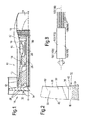
Figure 3 is a perspective view of an apparatus for shaping an edge of an aerofoil according to the present invention. -
Figure 4 is a plan view of the apparatus for shaping an edge of an aerofoil shown infigure 3 . -
Figure 5 is a view in the direction of arrow A infigure 3 showing a support structure of the apparatus for shaping an edge of an aerofoil. -
Figure 6 is an enlarged perspective view of part of the apparatus shown infigure 3 showing a brush, a motor and a clamp. -
Figure 7 is a view of the apparatus for shaping an edge of an aerofoil according to the present invention installed on a milling machine. -
Figure 8 is an enlarged view of a brush. - A turbofan
gas turbine engine 10, as shown infigure 1 , comprises in flow series an intake 11, afan 12, anintermediate pressure compressor 13, ahigh pressure compressor 14, acombustor 15, ahigh pressure turbine 16, anintermediate pressure turbine 17, alow pressure turbine 18 and anexhaust 19. Thehigh pressure turbine 16 is arranged to drive thehigh pressure compressor 14 via afirst shaft 26. Theintermediate pressure turbine 17 is arranged to drive theintermediate pressure compressor 14 via asecond shaft 28 and thelow pressure turbine 19 is arranged to drive thefan 12 via athird shaft 30. In operation air flows into the intake 11 and is compressed by thefan 12. A first portion of the air flows through, and is compressed by, theintermediate pressure compressor 13 and thehigh pressure compressor 14 and is supplied to thecombustor 15. Fuel is injected into thecombustor 15 and is burnt in the air to produce hot exhaust gases which flow through, and drive, thehigh pressure turbine 16, theintermediate pressure turbine 17 and thelow pressure turbine 18. The hot exhaust gases leaving thelow pressure turbine 18 flow through theexhaust 19 to provide propulsive thrust. A second portion of the air bypasses the main engine to provide propulsive thrust. - The
fan 12, as shown infigure 2 , comprises afan rotor assembly 32 comprising a fan rotor, a fan disc, 34 and a plurality of circumferentially spaced radially outwardly extendingfan rotor blades 36. The fan rotor, fan disc, 34 has arim 38 and a plurality of circumferentially spacedslots 40 are provided in therim 38 of the fan rotor,fan disc 34. Eachfan rotor blade 36 has aroot 42 and theroot 42 of eachfan rotor blade 36 is arranged in a corresponding one of theslots 40 in therim 38 of the fan rotor,fan disc 34. Theroot 42 of eachfan rotor blade 36 is firtree shaped, or dovetail shaped, in cross-section and eachslot 40 is correspondingly shaped to receive theroot 42 of the correspondingfan rotor blade 36. Alternatively thefan rotor blades 36 are integral with the fan rotor, fan disc, 34 and thefan rotor blades 36 are friction welded, laser welded, electron beam welded or diffusion bonded to the periphery of the fan rotor, fan disc, 34. - Each
fan rotor blade 36 also has anaerofoil 44 and theaerofoil 44 of eachfan rotor blade 36 has aleading edge 46, a trailingedge 48, aconvex suction surface 50 extending from the leadingedge 46 to the trailingedge 48 and aconcave pressure surface 52 extending from the leadingedge 46 to the tailingedge 48. The leadingedge 46 of theaerofoil 44 of eachfan rotor blade 36 is generally elliptical in profile, but other suitable shapes may be used. - As mentioned previously the
leading edges 46 of theaerofoils 44 of thefan rotor blades 36 suffer from erosion during operation of the turbofangas turbine engine 10 and the aerodynamic efficiency and surge margin of thefan 12 is reduced. Thus, it is desirable to restore theleading edges 46 of theaerofoils 44 of thefan rotor blades 36 back to their original shape. - An
apparatus 100 for shaping anedge 46 of anaerofoil 44, as shown infigures 3 to 8 comprises afirst brush 102 and asecond brush 104. Eachbrush bristles bristles brush figure 8 . Afirst motor 110 is arranged to rotate thefirst brush 102 about afirst axis 112 and thefirst axis 112 is arranged substantially parallel to thebristles 106 of thefirst brush 102. Asecond motor 114 is arranged to rotate thesecond brush 104 about asecond axis 116 and thesecond axis 116 is arranged substantially parallel to thebristles 108 of thesecond brush 104. Asupport structure 118 is arranged to hold thefirst brush 102 such that thefirst axis 112 intersects afirst surface 54 of anedge 46 of anaerofoil 44 and thesupport structure 118 is arranged to hold thesecond brush 104 such that thesecond axis 116 intersects asecond surface 56 of theedge 46 of theaerofoil 44. There are means 120 to position, or move, thefirst brush 102 such that thefirst brush 102 contacts thefirst surface 54 of theedge 46 of theaerofoil 44 and there aremeans 122 to position, or move, thesecond brush 104 such that thesecond brush 104 contacts thesecond surface 56 of theedge 46 of theaerofoil 44. There are means 124 to produce relative movement thefirst brush 102 and thesecond brush 104 and theaerofoil 44 such that thefirst brush 102 and thesecond brush 104 move longitudinally along theedge 46 of theaerofoil 44 to shape theedge 46 of theaerofoil 44. The first andsecond surfaces leading edge 46 of theaerofoil 44. Thesupport structure 118 comprises a first member, a plate member, 126 having a firstcurved slot 128 and a secondcurved slot 130, as shown infigure 5 . Ahousing 132 of thefirst motor 110 is clamped between afirst clamp member 134 and asecond clamp member 136 using a first pair of fasteners, e.g. two bolts, 138 and 140 which pass throughapertures first clamp member 134 and are secured in respective aligned threadedapertures 146 and 148 in thesecond clamp member 136, as shown infigures 3 and6 . Ahousing 150 of thesecond motor 114 is clamped between athird clamp member 152 and afourth clamp member 154 using a second pair of fasteners, e.g. two bolts, 156 and 158 which pass throughapertures third clamp member 152 and are secured in respective aligned threadedapertures 164 and 166 in thefourth clamp member 154, as shown infigure 3 . Thesecond clamp member 136 has a first pair ofparallel slots fourth clamp member 154 has a second pair ofparallel slots figure 6 . A third pair of fasteners, e.g. two nuts bolts, 176 and 178 extend through the first pair ofparallel slots curved slot 128 such that thefirst motor 110 andfirst brush 102 are movable in an arc along the firstcurved slot 128 to vary the angle of the axis ofrotation 112 of thefirst brush 102 relative to the leadingedge 46 of theaerofoil 44. A fourth pair of fasteners, e.g. two nuts and bolts, 180 and 182 extend through the second pair ofparallel slots curved slot 130 such that thesecond motor 114 andsecond brush 102 are movable in an arc along the secondcurved slot 130 to vary the angle of the axis ofrotation 116 of thesecond brush 102 relative to the leadingedge 46 of theaerofoil 44. The first pair ofparallel slots first brush 102 andfirst motor 110 to be moved towards or away from the leadingedge 46 of theaerofoil 44 by un-tightening the third pair offasteners parallel slots second brush 104 andsecond motor 114 to be moved towards or away from the leadingedge 46 of theaerofoil 44 by un-tightening the fourth pair offasteners 180 and 182. - The
support structure 118 is arranged to hold the first andsecond brushes first axis 112 and thesecond axis 116 intersect the first andsecond surfaces support structure 118 is arranged to hold the first andsecond brushes first axis 112 and thesecond axis 116 intersect the first andsecond surfaces support structure 118 is arranged to hold the first andsecond brushes first axis 112 and thesecond axis 116 intersect the first andsecond surfaces - The
support structure 118 comprises an adjuster to vary the angle at which thefirst axis 112 and thesecond axis 116 of the first andsecond brushes second surfaces curved slot 128, the secondcurved slot 130, the third pair offasteners fasteners 180 and 182. - The
first brush 102 and/or thesecond brush 104 comprise alumina bristles 106, 108, but other suitable abrasive bristles may be used. The first andsecond brushes sleeve bristles bristles sleeves screw figure 8 . - The
first motor 110 and/or thesecond motor 114 may comprise an electric motor, a hydraulic motor or a pneumatic motor. - The
first axis 112 and thesecond axis 114 may be arranged in a common plane, alternatively thefirst axis 112 and thesecond axis 114 may be arranged in two parallel planes as shown infigure 4 . Thefirst brush 102 and thesecond brush 104 may be arranged to rotate in opposite directions to prevent damage to thefirst brush 102 and/or damage to thesecond brush 104 if there is a possibility that the bristles of the first andsecond brushes first brush 102 and thesecond brush 104 may be arranged to rotate in the same direction if there is no possibility that the bristles of the first andsecond brushes - The
apparatus 100 may be mounted on a milling machine and anaerofoil 44 may be held by the milling machine. As seen infigure 6 , theaerofoil 44 is held such that it extends substantially vertically from the milling machine and theedge 46 extends substantially horizontally. In operation, initially thefirst axis 112 is arranged to intersect thefirst surface 54 of theedge 46 of theaerofoil 44 and thesecond axis 116 is arranged to intersect thesecond surface 56 of theedge 46 of theaerofoil 44. Then thefirst brush 102 is positioned, or moved, such that thefirst brush 102 contacts thefirst surface 54 of theedge 46 of theaerofoil 44 and thesecond brush 104 is positioned, moved, such that thesecond brush 104 contacts thesecond surface 56 of theedge 46 of the aerofoil. Then thefirst brush 102 is rotated about thefirst axis 112 and thesecond brush 104 is rotated about thesecond axis 116 and relative movement is provided between thefirst brush 102 and thesecond brush 104 on the one hand and theaerofoil 44 on the other hand such that thefirst brush 102 and thesecond brush 104 move longitudinally along theedge 46 of theaerofoil 14 to shape theedge 46 of theaerofoil 44 and in particular shape thefirst surface 54 and thesecond surface 56 of theedge 46 of theaerofoil 44. Either the first andsecond brushes support structure 118 are held stationary and theaerofoil 44 is moved or the first andsecond brushes support structure 118 are moved and theaerofoil 44 is held stationary. The first andsecond axes edge 46 of theaerofoil 44 and are arranged at angles W and X in the range of 30° to 75°, preferably 55° to 75°, relative to the vertical line V and the first andsecond axes first axis 112 and thesecond axis 114 are arranged in two parallel planes such that the first andsecond brushes second axes edge 46 of theaerofoil 44 if theedge 46 of theaerofoil 44 is asymmetric, due to the design of theaerofoil 44 or by preferential erosion of one side of theedge 46 of theaerofoil 44. - The rotational speed of the first and
second brushes second brushes edge 46 of theaerofoil 44 to take into account the thickness of theaerofoil 44 and the angle of the axes ofrotation second brushes edge 46 of theaerofoil 44. The angle of the brushes with respect to the aerofoil, the free length of the bristles, the overall depth of cut of the brushes against the aerofoil, the number of cuts of the brushes along the edge of the aerofoil at different positions relative to the aerofoil, the number of passes of the brushes along the edge of the aerofoil at the same position relative to the aerofoil, the rotational speed of the brushes and the feed rate, the speed, at which the brushes move along the edge of the aerofoil may all be varied to vary the ellipse ratio for the edge of the aerofoil. Changing the angle of the brushes has a significant effect on the ellipse ratio. Changing the angle of the brushes changes the ellipse ratio and in particular increasing the angle of the brushes increases the ellipse ratio. - In one example the brushes were set at an angle of 60°, the feed rate was 200mm/min, the brush rotation speed was 3000rpm, number of passes was 4, number of stages was 4, the depth of cut was 0.53mm, effective depth of cut was 0.265mm and the brushes were XEBEC A21 brushes.
- The method may comprise shaping the edge of a gas turbine engine aerofoil. The method may comprise shaping the edge of a fan blade, a fan outlet guide vane, a compressor blade or a compressor vane. The method may comprise shaping a leading edge of an aerofoil, e.g. a blade or a vane. The aerofoil may comprise a titanium alloy, a nickel or steel. An example of a titanium alloy is titanium 6-4 consisting of 6wt% aluminium, 4wt% vanadium and the balance titanium plus incidental impurities and minor additions. An example of a nickel alloy is Inconel 718.
- The method may comprise reshaping an edge of a worn aerofoil. The method may comprise shaping the edge of the aerofoil while the aerofoil is in the gas turbine engine. The aerofoil may be an aerofoil of integrally bladed disc or a separate aerofoil mounted in a slot in the periphery of a disc or separate aerofoil mounted in a slot in the periphery of a drum. The method may comprise removing a casing from gas turbine engine and then shaping the aerofoil while the aerofoil is on an integrally bladed disc or while the aerofoil is mounted in a slot in the periphery of a disc or while the aerofoil is mounted in a slot in the periphery of a drum of the gas turbine engine. The method may comprise mounting the apparatus on an aerofoil and then moving the brushes along the edge of the aerofoil. The method may comprise passing the brushes through an aperture in a casing with a boroscope and shaping the edge of an aerofoil while the aerofoil is in the gas turbine engine and in this case the brushes and associated structures and drives etc may be miniaturised.
- Although the present invention has been described with reference to the use of a first motor to drive the first brush directly and a second motor arranged to drive the second brush directly, it may be possible to provide other arrangements to drive the first brush and the second brush, e.g. a first device and a second device respectively. The first device may comprise a first motor arranged to drive the first brush via gears and the second device may comprise a second motor arranged to drive the second brush via gears. Alternatively the first device and the second device may share a single motor which is arranged to drive both the first device and the second device.
- Although the present invention has been described with reference to the use of a plate with curved slots to enable adjustment of the first and second angles of the first and second brushes respectively it is equally possible to use other suitable devices, e.g. first and second curved tracks along which the first and second brushes may move.
- Although the present invention has been described with reference to a first brush arranged such that the first axis intersects a first surface of an edge of an aerofoil and a second brush arranged such that the second axis intersects a second surface of the edge of the aerofoil it is equally possible to provide a plurality of first brushes arranged such that the axis of each of the first brushes intersect a first surface of an edge of an aerofoil and a plurality of second brushes arranged such that the axis of each of the second brushes intersect a second surface of the edge of the aerofoil. The axes of the first brushes may be parallel and the axes of the second brushes may be parallel.
- The present invention is equally applicable to aerofoils for other gas turbine engines, e.g. turbojet, turboprop and turboshaft gas turbine engines and for gas turbine engine with one, two or more shafts. The present invention is equally applicable for shaping edges, e.g. leading edges, of blades or vanes.
Claims (17)
- An apparatus (100) for shaping an edge (46) of an aerofoil (44), the apparatus (100) comprising a first brush (102) and a second brush (104), each brush (102,104) comprising a plurality of bristles extending substantially parallel to each other, a first device (110) arranged to rotate the first brush (102) about a first axis (112), the first axis (112) being arranged substantially parallel to the bristles of the first brush (102), a second device (114) arranged to rotate the second brush (104) about a second axis (116), the second axis (116) being arranged substantially parallel to the bristles of the second brush (104), a support structure (118) arranged to hold the first brush (102) such that the first axis (112) intersects a first surface (54) of an edge (46) of an aerofoil (44) and arranged to hold the second brush (104) such that the second axis (116) intersects a second surface (56) of the edge (46) of the aerofoil (44), means to move the first brush (102) such that the first brush (102) contacts the first surface (54) of the edge (46) and means to move the second brush (104) such that the second brush (104) contacts the second surface (56) of the edge (46), means to produce relative movement between the first brush (102) and the second brush (104) and the aerofoil (44) such that the first brush (102) and the second brush (104) move longitudinally along the edge (46) of the aerofoil (44) to shape the edge (46) of the aerofoil (44).
- An apparatus as claimed in claims 1 comprising a plurality of first brushes and a plurality of second brushes, each brush comprising a plurality of bristles extending substantially parallel to each other, a first device arranged to rotate each first brush about a respective first axis, each first axis being arranged substantially parallel to the bristles of the respective first brush, a second device arranged to rotate each second brush about a respective second axis, each second axis being arranged substantially parallel to the bristles of the respective second brush, a support structure arranged to hold the plurality of first brushes such that each first axis intersects a first surface of an edge of an aerofoil and arranged to hold the plurality of second brushes such that each second axis intersects a second surface of the edge of the aerofoil, means to move the plurality of first brushes such that the first brushes contact the first surface of the edge and means to move the plurality of second brushes such that the second brushes contact the second surface of the edge, means to produce relative movement between the plurality of first brushes and the plurality of second brushes and the aerofoil such that the plurality of first brushes and the plurality of second brushes move longitudinally along the edge of the aerofoil to shape the edge of the aerofoil.
- An apparatus as claimed in claim 1 or claim 2 wherein the support structure is arranged to hold each of the first and second brushes (102, 104) such that each first axis (112) and each second axis (116) intersect the first and second surfaces (54, 56) respectively at angle in the range of 30° to 75°.
- An apparatus as claimed in claim 3 wherein the support structure is arranged to hold each of the first and second brushes (102, 104) such that each first axis (112) and each second axis (116) intersect the first and second surfaces (54, 56) respectively at angle of 55° to 75°.
- An apparatus as claimed in any of claims 1 to 4 wherein the support structure comprises an adjuster (128, 130, 176, 178, 180, 182) to vary the angle at which the first axis (112) and the second axis (116) of each of the first and second brushes (102, 140) intersect the first and second surfaces (54, 56) respectively.
- An apparatus as claimed in any of claims 1 to 5 wherein each first brush (102) and/or each second brush (104) comprises alumina bristles or silicon carbide bristles.
- An apparatus as claimed in any of claims 1 to 6 wherein the first device (110) comprises an electric motor, a hydraulic motor or a pneumatic motor and the second device (114) comprises an electric motor, a hydraulic motor or a pneumatic motor or the first device (110) and the second device (114) comprise a single electric motor, a single hydraulic motor or a single pneumatic motor.
- An apparatus as claimed in claim 1 wherein the first axis (112) and the second axis (116) are arranged in a plane or the first axis (112) and the second axis (114) are arranged in two parallel planes.
- A method of shaping an edge (46) of an aerofoil (44), the method comprising:-a) providing a first brush (102) and a second brush (104), each brush (102, 104) comprising a plurality of bristles extending substantially parallel to each other,b) rotating the first brush (102) about a first axis (112) and rotating the second brush (104) about a second axis (116), the first axis (112) being arranged substantially parallel to the bristles of the first brush (102) and the second axis (116) being arranged substantially parallel to the bristles of the second brush (104),c) arranging the first axis (112) to intersect a first surface (54) of an edge (46) of an aerofoil (44) and arranging the second axis (116) to intersect a second surface (56) of the edge (46) of the aerofoil (44),d) moving the first brush (102) such that the first brush (102) contacts the first surface (54) of the edge (46) and moving the second brush (104) such that the second brush (104) contacts the second surface (56) of the edge (46),e) producing relative movement between the first brush (102) and the second brush (104) and the aerofoil (44) such that the first brush (102) and the second brush (104) move longitudinally along the edge (46) of the aerofoil (44) to shape the edge (46) of the aerofoil (44).
- A method as claimed in claim 9 comprising:-a) providing a plurality of first brushes and a plurality of second brushes, each brush comprising a plurality of bristles extending substantially parallel to each other,b) rotating each first brush about a respective first axis and rotating each second brush about a respective second axis, each first axis being arranged substantially parallel to the bristles of the respective first brush and each second axis being arranged substantially parallel to the bristles of the respective second brush,c) arranging each first axis to intersect a first surface of an edge of an aerofoil and arranging each second axis to intersect a second surface of the edge of the aerofoil,d) moving the first brushes such that the first brushes contact the first surface of the edge and moving the second brushes such that the second brushes contact the second surface of the edge,e) producing relative movement between the first brushes and the second brushes and the aerofoil such that the first brushes and the second brushes move longitudinally along the edge of the aerofoil to shape the edge of the aerofoil.
- A method as claimed in claim 9 or claim 10 comprising arranging each first axis (112) and each second axis (116) to intersect the first and second surfaces (54, 56) respectively at angle in the range of 30° to 75°.
- A method as claimed in claim 11 comprising arranging each first axis (112) and each second axis (116) to intersect the first and second surfaces (54, 56) respectively at angle in the range of 55° to 75°.
- A method as claimed in any of claims 9 to 12 comprising varying the angle at which each first axis (112) and each second axis (116) intersect the first and second surfaces (54, 56) respectively.
- A method as claimed in any of claims 9 to 13 wherein each first brush (102) and/or each second brush (104) comprises alumina bristles or silicon carbide bristles.
- A method as claimed in any of claims 9 to 14 comprising arranging the first axis (112) and the second axis (116) in a plane or arranging the first axis (112) and the second axis (116) in two parallel planes.
- A method as claimed in any of claims 9 to 15 comprising shaping the leading edge (46) of an aerofoil (44) or reshaping an edge (46) of a worn aerofoil (44).
- A method as claimed in any of claims 9 to 16 comprising shaping the edge (46) of a fan blade, a fan outlet guide vane, a compressor blade or a compressor vane.
Applications Claiming Priority (1)
| Application Number | Priority Date | Filing Date | Title |
|---|---|---|---|
| GB1109303.6A GB2491398B (en) | 2011-06-03 | 2011-06-03 | An apparatus and a method of shaping an edge of an aerofoil |
Publications (1)
| Publication Number | Publication Date |
|---|---|
| EP2530243A2 true EP2530243A2 (en) | 2012-12-05 |
Family
ID=44343336
Family Applications (1)
| Application Number | Title | Priority Date | Filing Date |
|---|---|---|---|
| EP12169238A Withdrawn EP2530243A2 (en) | 2011-06-03 | 2012-05-24 | An apparatus and a method of shaping an edge of an aerofoil |
Country Status (4)
| Country | Link |
|---|---|
| US (1) | US9039490B2 (en) |
| EP (1) | EP2530243A2 (en) |
| GB (1) | GB2491398B (en) |
| SG (1) | SG185918A1 (en) |
Cited By (2)
| Publication number | Priority date | Publication date | Assignee | Title |
|---|---|---|---|---|
| CN110026863A (en) * | 2019-04-30 | 2019-07-19 | 深圳市鑫汇达机械设计有限公司 | A kind of lifting airscrew grinding device |
| CN110788695A (en) * | 2019-10-29 | 2020-02-14 | 滁州市高洁特玻璃制品有限公司 | Adjustable dust removal grinding device of glass board |
Families Citing this family (6)
| Publication number | Priority date | Publication date | Assignee | Title |
|---|---|---|---|---|
| FR2964585B1 (en) * | 2010-09-15 | 2012-10-05 | Snecma | METHOD AND MACHINE TOOL FOR ADJUSTING THE CONTOUR OF A WORKPIECE |
| GB2491397B (en) * | 2011-06-03 | 2013-11-27 | Rolls Royce Plc | An apparatus and a method of shaping an edge of an aerofoil |
| CN105397590B (en) * | 2015-12-29 | 2017-05-31 | 中信戴卡股份有限公司 | A kind of online burr remover of the wheel of size adjustable |
| US10125611B2 (en) | 2016-02-17 | 2018-11-13 | General Electric Company | System and method for in situ repair of turbine blades of gas turbine engines |
| CN109158978A (en) * | 2018-11-06 | 2019-01-08 | 中信戴卡股份有限公司 | A kind of wheel loss of weight nest cleaning plant |
| CN114682992B (en) * | 2022-02-25 | 2023-10-10 | 镇江福斯特汽车零部件有限公司 | Preparation shaping device of special self-adjusting regulator for automobile brake |
Family Cites Families (23)
| Publication number | Priority date | Publication date | Assignee | Title |
|---|---|---|---|---|
| US3473181A (en) * | 1968-02-28 | 1969-10-21 | Lenco Inc | Dual mounted cup steel brushes for metal cleaning |
| US5105583A (en) * | 1990-08-29 | 1992-04-21 | Hammond Machinery Inc. | Workpiece deburring method and apparatus |
| US5197191A (en) * | 1991-03-04 | 1993-03-30 | General Electric Company | Repair of airfoil edges |
| JPH07164293A (en) * | 1993-12-15 | 1995-06-27 | Yamaha Motor Co Ltd | Deburring brush device and deburring brush and machining center installing holder |
| US6302625B1 (en) * | 1999-10-15 | 2001-10-16 | United Technologies Corporation | Method and apparatus for refurbishing a gas turbine airfoil |
| CH695442A5 (en) * | 2002-01-31 | 2006-05-31 | Alstom Technology Ltd | Method and apparatus for round-machining a blank in a milling machine. |
| ATE327080T1 (en) * | 2002-02-28 | 2006-06-15 | Nina Himmer | AUTOMATED PROCESSING UNIT FOR A WORKSTATION |
| DE10338682B4 (en) * | 2002-09-25 | 2010-03-18 | Georg Weber | Device for processing substantially flat workpieces |
| US7032279B2 (en) * | 2002-10-18 | 2006-04-25 | General Electric Company | Apparatus and methods for repairing compressor airfoils in situ |
| DE202004002905U1 (en) * | 2003-09-08 | 2004-04-29 | ProFin Prograssive Finish AG | Tool for processing surfaces, edge areas and contours |
| JP4258480B2 (en) * | 2005-03-15 | 2009-04-30 | トヨタ自動車株式会社 | Grinding machine and grinding system |
| GB0612925D0 (en) | 2006-06-29 | 2006-08-09 | Rolls Royce Plc | Method and system for measuring a component |
| DE102006036839A1 (en) * | 2006-08-07 | 2008-02-14 | Rolls-Royce Deutschland Ltd & Co Kg | Method for deburring power-unit edges e.g. for gas-turbine, involves deburring brush operated at prescribed cutting speed |
| WO2008077398A1 (en) * | 2006-12-22 | 2008-07-03 | Vestas Wind Systems A/S | Automatic grinding machine for grinding elongated objects, like rotor blades for windturbines |
| DE102007031656A1 (en) * | 2007-07-06 | 2009-01-08 | Heesemann, Jürgen, Dipl.-Ing. | grinding machine |
| DE102007041805A1 (en) | 2007-08-30 | 2009-03-05 | Rolls-Royce Deutschland Ltd & Co Kg | Method and apparatus for blade tip machining of impeller drums of turbomachinery |
| CN101497178A (en) * | 2008-02-01 | 2009-08-05 | 鸿富锦精密工业(深圳)有限公司 | Sanding device |
| DE102008017624A1 (en) | 2008-04-04 | 2009-10-08 | Rolls-Royce Deutschland Ltd & Co Kg | Method for aerodynamically shaping the leading edge of blisk blades |
| GB0812478D0 (en) | 2008-07-09 | 2008-08-13 | Rolls Royce Plc | An apparatus and a method of measuring erosion of an edge of a turbomachine aerofoil |
| GB0902333D0 (en) * | 2009-02-13 | 2009-04-01 | Rolls Royce Plc | A surface treatment device |
| GB2491397B (en) * | 2011-06-03 | 2013-11-27 | Rolls Royce Plc | An apparatus and a method of shaping an edge of an aerofoil |
| EP2730370B1 (en) * | 2012-11-13 | 2015-10-14 | Siemens Aktiengesellschaft | Method to adjust a predetermined radial tip clearance of a turbomachine blade |
| US9017141B2 (en) * | 2013-01-04 | 2015-04-28 | White Drive Products, Inc. | Deburring machine and method for deburring |
-
2011
- 2011-06-03 GB GB1109303.6A patent/GB2491398B/en not_active Expired - Fee Related
-
2012
- 2012-05-24 US US13/479,881 patent/US9039490B2/en not_active Expired - Fee Related
- 2012-05-24 EP EP12169238A patent/EP2530243A2/en not_active Withdrawn
- 2012-05-25 SG SG2012038667A patent/SG185918A1/en unknown
Non-Patent Citations (1)
| Title |
|---|
| None |
Cited By (4)
| Publication number | Priority date | Publication date | Assignee | Title |
|---|---|---|---|---|
| CN110026863A (en) * | 2019-04-30 | 2019-07-19 | 深圳市鑫汇达机械设计有限公司 | A kind of lifting airscrew grinding device |
| CN110026863B (en) * | 2019-04-30 | 2020-11-10 | 义乌国信土地规划咨询有限公司 | Helicopter rotor grinding device |
| CN110788695A (en) * | 2019-10-29 | 2020-02-14 | 滁州市高洁特玻璃制品有限公司 | Adjustable dust removal grinding device of glass board |
| CN110788695B (en) * | 2019-10-29 | 2021-10-19 | 滁州市高洁特玻璃制品有限公司 | Adjustable dust removal grinding device of glass board |
Also Published As
| Publication number | Publication date |
|---|---|
| GB2491398B (en) | 2013-11-27 |
| GB2491398A (en) | 2012-12-05 |
| GB201109303D0 (en) | 2011-07-20 |
| SG185918A1 (en) | 2012-12-28 |
| US20120309274A1 (en) | 2012-12-06 |
| US9039490B2 (en) | 2015-05-26 |
Similar Documents
| Publication | Publication Date | Title |
|---|---|---|
| US9039490B2 (en) | Method of shaping an edge of an aerofoil | |
| US20150000132A1 (en) | Apparatus and a method of shaping an edge of an aerofoil | |
| US7887299B2 (en) | Rotary body for turbo machinery with mistuned blades | |
| US7874794B2 (en) | Blade row for a rotary machine and method of fabricating same | |
| EP3108123B1 (en) | Turbofan engine with geared architecture and lpc airfoils | |
| GB2475140A (en) | An Exhaust Ring and Method to Reduce Turbine Acoustic Signature | |
| EP3017898A1 (en) | Attrition liner machining tool | |
| CN1880729A (en) | Turbine blade and method of fabricating same | |
| EP3093436A1 (en) | Blade/disk dovetail backcut for blade/disk stress reduction for a second stage of a turbomachine | |
| EP3315734B1 (en) | Apparatus for circumferential separation of turbine blades | |
| EP2458156A2 (en) | Turbine engine stator e.g. a compressor stator | |
| US20060018753A1 (en) | High pressure tandem turbine | |
| EP2486241B1 (en) | Guide vane with a winglet for an energy converting machine and machine for converting energy comprising the guide vane | |
| EP2204536B1 (en) | Method of tuning a compressor stator blade. | |
| EP3124754A1 (en) | Near flow path seal for a turbomachine | |
| US11053796B2 (en) | Turbomachine modification apparatus and method | |
| US10072512B2 (en) | Turbine nozzle and shroud | |
| US10330113B2 (en) | Method of manufacturing a gas turbine engine | |
| US11141800B2 (en) | Device and method for re-contouring a gas turbine blade | |
| EP3696380A1 (en) | Adapter for positioning a machining tool between two aerofoils | |
| EP4159370A1 (en) | Tool and repair method for removing a thermal barrier coating | |
| KR20230117376A (en) | Methods for forming or repairing parts having protruding sections, and related turbomachinery parts | |
| KR20230113322A (en) | Methods for forming or repairing parts having protruding sections, and related turbomachinery parts | |
| EP3108121B1 (en) | Turbofan engine with geared architecture and lpc airfoils |
Legal Events
| Date | Code | Title | Description |
|---|---|---|---|
| PUAI | Public reference made under article 153(3) epc to a published international application that has entered the european phase |
Free format text: ORIGINAL CODE: 0009012 |
|
| AK | Designated contracting states |
Kind code of ref document: A2 Designated state(s): AL AT BE BG CH CY CZ DE DK EE ES FI FR GB GR HR HU IE IS IT LI LT LU LV MC MK MT NL NO PL PT RO RS SE SI SK SM TR |
|
| AX | Request for extension of the european patent |
Extension state: BA ME |
|
| RBV | Designated contracting states (corrected) |
Designated state(s): AL AT BE BG CH CY CZ DE DK EE ES FI FR GR HR HU IE IS IT LI LT LU LV MC MK MT NL NO PL PT RO RS SE SI SK SM TR |
|
| RAP1 | Party data changed (applicant data changed or rights of an application transferred) |
Owner name: ROLLS-ROYCE PLC |
|
| STAA | Information on the status of an ep patent application or granted ep patent |
Free format text: STATUS: THE APPLICATION IS DEEMED TO BE WITHDRAWN |
|
| 18D | Application deemed to be withdrawn |
Effective date: 20151201 |