EP2530018A1 - Systems and methods for refueling spacecraft - Google Patents
Systems and methods for refueling spacecraft Download PDFInfo
- Publication number
- EP2530018A1 EP2530018A1 EP12164864A EP12164864A EP2530018A1 EP 2530018 A1 EP2530018 A1 EP 2530018A1 EP 12164864 A EP12164864 A EP 12164864A EP 12164864 A EP12164864 A EP 12164864A EP 2530018 A1 EP2530018 A1 EP 2530018A1
- Authority
- EP
- European Patent Office
- Prior art keywords
- propellant
- spacecraft
- ullage
- tank
- client
- Prior art date
- Legal status (The legal status is an assumption and is not a legal conclusion. Google has not performed a legal analysis and makes no representation as to the accuracy of the status listed.)
- Granted
Links
Images

Classifications
-
- B—PERFORMING OPERATIONS; TRANSPORTING
- B64—AIRCRAFT; AVIATION; COSMONAUTICS
- B64G—COSMONAUTICS; VEHICLES OR EQUIPMENT THEREFOR
- B64G1/00—Cosmonautic vehicles
- B64G1/22—Parts of, or equipment specially adapted for fitting in or to, cosmonautic vehicles
- B64G1/40—Arrangements or adaptations of propulsion systems
- B64G1/402—Propellant tanks; Feeding propellants
- B64G1/4024—Propellant tanks; Feeding propellants refuelling in space
Definitions
- the following disclosure relates generally to systems and methods for transferring propellant between two spacecraft and, more particularly, to on-orbit satellite refueling.
- the propulsion system can include both mono-propellant rocket thrusters (i.e., thrusters that use a single type of propellant, such as hydrazine) and bi-propellant thrusters (i.e., thrusters that use two types of propellant, such as a fuel (e.g., monomethylhydrazine (“MMH”)) and an oxidizer (e.g., nitrogen tetroxide (“NTO”)).
- a fuel e.g., monomethylhydrazine (“MMH”)
- NTO nitrogen tetroxide
- One method of on-orbit satellite refueling includes docking a "servicing" satellite to an orbiting "client" satellite in need of propellant.
- a first propellant line from a supply tank on the servicing satellite is releasably connected to a second propellant line leading to the propellant tank on the client satellite.
- the propellant from the supply tank is then transferred to the client tank via the mated propellant lines.
- the ullage typically includes some liquid fuel vapor.
- One problem with the refueling method described above is that, as the client tank is filled, the ullage in the client tank vents to space. Venting this fuel-laced pressurant to space in close proximity to the client and servicing satellites can contaminate and damage solar panels and/or other sensitive equipment on the satellites.
- a method for transferring propellant from a first spacecraft to a second spacecraft in accordance with one aspect of the invention includes releasably connecting a first propellant conduit carried by the first spacecraft to a second propellant conduit carried by the second spacecraft, and releasably connecting a first ullage conduit carried by the first spacecraft to a second ullage conduit carried by the second spacecraft.
- the method further includes transferring propellant from the first spacecraft to the second spacecraft via the first and second propellant conduits, and transferring ullage from the second spacecraft to the first spacecraft via the first and second ullage conduits.
- transferring propellant from the first spacecraft to the second spacecraft can include transferring propellant from a first propellant tank carried by the first spacecraft to a second propellant tank carried by the second spacecraft, and transferring ullage from the second spacecraft to the first spacecraft can include transferring ullage from the second propellant tank to the first propellant tank.
- a method of refueling spacecraft in accordance with another aspect of the invention includes releasably coupling a first spacecraft to a second spacecraft, and transferring propellant from a first tank carried by the first spacecraft to a second tank carried by the second spacecraft.
- the method can further include transferring ullage from the second tank to the first tank while transferring the propellant from the first tank to the second tank.
- a propellant supply spacecraft configured in accordance with a further aspect of the invention includes a first propellant tank and a spacecraft refueling interface.
- the first propellant tank includes a propellant outlet and an ullage inlet.
- the refueling interface includes a first propellant transfer coupling in fluid communication with the propellant outlet, and a first ullage transfer coupling in fluid communication with the ullage inlet.
- the first propellant transferring coupling is configured to be releasably connected to a second propellant transfer coupling carried by a client spacecraft so that propellant from the first propellant tank can flow into the second propellant tank.
- the first ullage transfer coupling is configured to be releasably connected to a second ullage transfer coupling carried by the second spacecraft so that ullage from the second propellant tank can flow into the first propellant tank while the propellant is flowing from the first propellant tank into the second propellant tank.
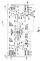
- Figure 1 is a partially schematic diagram of a spacecraft refueling system configured in accordance with an embodiment of the invention.
- Figure 2 is a flow diagram illustrating a routine for refueling a spacecraft in accordance with an embodiment of the invention.
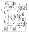
- Figure 3 is a partially schematic diagram of a spacecraft refueling system configured in accordance with another embodiment of the invention.
- FIG. 1 is a partially schematic diagram of a spacecraft refueling system 100 configured in accordance with an embodiment of the invention.
- the spacecraft refueling system 100 includes a propellant supply spacecraft 110 and a propellant receiving spacecraft 160.
- the propellant supply spacecraft 110 is referred to below as the "supply spacecraft 110”
- the propellant receiving spacecraft 160 is referred to below as the "client spacecraft 160.”
- the client spacecraft 160 can be an orbiting satellite, such as a research satellite, a communication satellite, a weather satellite, a navigational satellite, etc., having a mono-propellant propulsion system.
- the supply spacecraft 110 can be another satellite or spacecraft that has docked with the client spacecraft 160 for the purpose of refueling the client spacecraft 160.
- the supply spacecraft 110 can refuel the client spacecraft 160 by flowing propellant from a supply tank 120 to a receiving tank 170, while simultaneously flowing pressurant or "ullage" from the receiving tank 170 back into the supply tank 120.
- Transferring propellant in a closed-loop system such as this avoids venting fuel-rich ullage to space in close proximity to the supply spacecraft 110 and the client spacecraft 160, which could damage solar panels and/or other critical surfaces and equipment on the spacecraft.
- a further advantage of this approach is that it recycles the ullage from the receiving tank 170 and uses it to replenish the supply tank 120, thereby reducing the amount of stored ullage that needs to be carried aloft by the supply spacecraft 110.
- the supply spacecraft 110 can include a propulsion system 112 (e.g., a mono- propellant and/or bi-propellant propulsion system), a guidance system 114, and an on-board power system 116 (e.g., batteries, solar panels, etc.). These systems can be at least generally similar in structure and function to conventional spacecraft systems known in the art.
- the supply spacecraft 110 can also include a spacecraft controller 118.
- the controller 118 can include a processor 117 configured to execute computer-readable instructions stored in memory 119.
- the computer-readable instructions enable the controller 118 to control the propulsion system 112, the guidance system 114, and the power system 116.
- the computer-readable instructions also enable the controller 118 to control refueling operations associated with the propellant supply tank 120 (the "supply tank 120").
- the supply tank 120 carries a propellant 122 (identified as a first propellant portion 122a) suitable for use with monopropellant propulsion systems.
- propellants can include hydrazine, hydrogen peroxide, and/or other suitable monopropellants known in the art.
- the supply tank 120 can include a propellant management device (PMD) 124 to separate the propellant 122a from a pressurant or ullage 123 (identified as a first ullage portion 123a).
- Suitable ullages can include, for example, gaseous nitrogen (N 2 ), helium (He), etc.
- the PMD 124 can include a bladder, diaphragm, or other suitable positive expulsion device known in the art.
- the PMD 124 can include other types of PMD devices known in the art, depending on the type of propellant being used.
- surface tension type PMD devices such as a screen or vane type PMD, can be used.
- the supply spacecraft 120 can also include a first refueling interface 136a having a first propellant coupling 137a and a first ullage coupling 141a.
- the client spacecraft 160 can include a corresponding second refueling interface 136b having a second propellant coupling 137b and a second ullage coupling 141b.
- the first propellant coupling 137a is configured to releasably engage the second propellant coupling 137b
- the first ullage coupling 141a is configured to releasably engage the second ullage coupling 141b, when the first refueling interface 136a mates to the second refueling interface 136b.
- the propellant couplings 137, and the ullage couplings 141 can include various types of "quick-disconnect" fittings known in the art for releasably connecting fluid conduits together.
- a first propellant transfer conduit 132a operably extends from a propellant outlet 128 on the supply tank 120 to the first propellant coupling 137a on the first refueling interface 136a.
- the first propellant transfer conduit 132a is referred to below as the "first propellant line 132a.”
- the PMD 124 helps keep the propellant 122a over the propellant outlet 128 at all times.
- a propellant mover 130 e.g., a pump, such as an electrically driven mechanical pump, etc.
- a first ullage transfer conduit 142a operably extends from the first ullage coupling 141a on the first refueling interface 136a to an ullage inlet 126 on the supply tank 120.
- the first ullage transfer conduit 142a is referred to below as the "first ullage line 142a.”
- a first ullage valve 144a controls the flow of ullage through the first ullage line 142a.
- a first ullage storage tank 150a carries a portion of the ullage 123 (identified as a third ullage portion 123c).
- a third ullage valve 144c controls the flow of ullage from the storage tank 150a to the ullage inlet 126 if needed to supplement the ullage 123a in the supply tank 120 during, for example, the refueling procedures discussed in detail below.
- the client spacecraft 160 can include a propulsion system 162, a guidance system 164, and an on-board power system 166.
- the propulsion system 162 can include one or more mono-propellant thrusters 163 (illustrated individually as a first thruster 163a and a second thruster 163b).
- the client spacecraft 160 can further include a spacecraft controller 168.
- the controller 168 can include a processor 167 configured to execute computer-readable instructions stored in memory 169.
- the computer-readable instructions enable the controller 168 to control the propulsion system 162, the guidance system 164, and the power system 166.
- the computer-readable instructions also enable the controller 168 to control refueling operations associated with the propellant receiving tank 170.
- the propellant receiving tank 170 is referred to below as the "client tank 170.”
- the client tank 170 carries a portion of the propellant 122 (identified as a second propellant portion 122b) and a portion of the ullage 123 (identified as a second ullage portion 123b).
- a PMD 174 separates the ullage 123b from the propellant 122b.
- the PMD 174 can be at least generally similar in structure and function to the PMD 124 on the supply spacecraft 110.
- a second propellant transfer conduit 132b operably extends from the second propellant coupling 137b on the second refueling interface 136b to a propellant inlet 176 on the client tank 170.
- the second propellant transfer conduit 132b is referred to below as the "second propellant line 132b.”
- a second propellant transfer valve 134b controls the flow of propellant through the second propellant line 136b.
- a second ullage transfer conduit 142b operably extends from an ullage outlet 178 on the client tank 170 to the second ullage coupling 141b on the second refueling interface 136b.
- the second ullage transfer conduit 142b is referred to below as the "second ullage line 142b.”
- the PMD 174 helps keep the propellant 122b away from the ullage outlet 178 at all times.
- a second ullage valve 144b controls the flow of ullage through the second ullage line 142b.
- a second ullage storage tank 150b carries a portion of the ullage 123 (identified as a fourth ullage portion 123d).
- a fourth ullage valve 144d controls the flow of ullage from the storage tank 150b to the supply tank 170 during, for example, operation of the propulsion system 162.
- Figure 2 is a flow diagram of a routine 200 for refueling a spacecraft in accordance with an embodiment of the invention.
- the routine 200 is described below with reference to the spacecraft refueling system 100 of Figure 1 .
- the supply-side controller 118 can implement those portions of the routine 200 carried out by the supply spacecraft 110
- the receive-side controller 168 can implement those portions of the routine 200 carried out by the client spacecraft 160.
- various portions of the routine 200 can be implemented by other processing devices residing wholly or in part on one or both of the supply spacecraft 110 and/or the client spacecraft 160.
- the routine 200 can also be employed by other spacecraft refueling systems.
- the routine 200 can be employed by other mono-propellant and/or bi-propellant refueling systems (such as the bi-propellant refueling system described below with reference to Figure 3 ).
- the first propellant line 132a is releasably connected to the second propellant line 132b.
- the propellant lines 132 can be automatically connected together when the first refueling interface 136a on the supply spacecraft 110 is mated to the second refueling interface 136b on the client spacecraft 160.
- the first propellant coupling 137a can be releasably engaged with the second propellant coupling 137b.
- the propellant couplings 137 can include suitable quick disconnects known in the art for this purpose.
- the first ullage line 142a is releasably connected to the second ullage line 142b.
- the first ullage coupling 141a can be releasably engaged with the second ullage coupling 141b as the first refueling interface 136a is mated to the second refueling interface 136b.
- the first propellant transfer valve 134a on the first propellant line 132a, and the second propellant transfer valve 134b on the second propellant line 132b are opened.
- the first ullage transfer valve 144a on the first ullage line 142a, and the second ullage transfer valve 144b on the second ullage line 142b are opened.
- the propellant 122a from the supply tank 120 flows into the client tank 170 via the propellant lines 132.
- the propellant mover 130 facilitates movement of the propellant 122a from the supply tank 120 to the client tank 170.
- the propellant 122a flows into the client tank 170, the displaced ullage 123b flows out of the client tank 170 and into the supply tank 120 via the ullage lines 142.
- the routine determines if refueling is complete. This can occur when the client tank 170 is at least approximately full of the propellant 122. If refueling is not complete, the routine returns to block 210 and repeats. When refueling is complete, the routine proceeds to block 216. In block 216, the first and second propellant transfer valves 134a,b, and the first and second ullage transfer valves 144a,b, are closed. In block 218, the first refueling interface 136a separates from the second refueling interface 136b.
- the first propellant coupling 136a disengages from the second propellant coupling 137b
- the first ullage coupling 141a disengages from the second ullage coupling 141b, thereby disconnecting the first fuel line 132a from the second fuel line 132b, and the first ullage line 142a from the second ullage line 142b.
- the routine is complete.
- the client spacecraft 160 can operate the thrusters 163 as needed to maintain proper orbit.
- a thruster valve 188 is opened allowing the propellant 122b to flow from the client tank 170 to the thrusters 163.
- the fourth ullage valve 144d is opened to allow the ullage 123d to flow into the client tank 170 and pressurize the propellant 122b.
- FIG 3 is a partially schematic diagram of a spacecraft refueling system 300 configured in accordance with another embodiment of the invention.
- the spacecraft refueling system 300 includes a supply spacecraft 310 and a client spacecraft 360.
- Many components and features of the supply spacecraft 310 and the client spacecraft 360 can be at least generally similar in structure and function to corresponding features of the supply spacecraft 110 and the client spacecraft 160, respectively, described in detail above with reference to Figures 1 and 2 .
- the client spacecraft 360 includes a bipropellant propulsion system 362 having a first thruster 363a and a second thruster 363b.
- the bipropellant propulsion system 362 can use a first propellant, such as a fuel 322 (identified as a first fuel portion 322a) carried by a first client tank 370a, and a second propellant, such as an oxidizer 325 (identified as a first oxidizer portion 325a) carried by a second client tank 370b.
- the fuel 322a can include monomethyl hydrazine (MMH), liquid hydrogen, RP1, etc.
- the oxidizer 325a can include nitrogen tetroxide (NTO), liquid oxygen, etc.
- the first propellant tank 370a and the second propellant tank 370b can include surface-tension type PMDs 374 (identified individually as a first PMD 374a and a second PMD 374b).
- Each of the PMDs 374 can include a plurality of screen/vanes 375 and one or more baffle systems 377 for collecting the propellant.
- the PMD 374a keeps the fuel 322a separate from an ullage 323 (identified individually as a first ullage portion 323a).
- the PMD 374b keeps the oxidizer 325a separate from a second portion of the ullage 323 (identified as a second ullage portion 323b).
- the supply spacecraft 310 includes a first supply tank 320a and a second supply tank 320b.
- the first supply tank 320a carries a portion of the fuel 322 (identified as a second fuel portion 322b) for refueling the first client tank 370a.
- the second supply tank 320b carries a portion of the oxidizer 325 (identified as a second oxidizer portion 325b) for replenishing the oxidizer in the second client tank 370b.
- a first refueling interface 336a on the supply spacecraft 310 is releasably mated to a second refueling interface 336b on the client spacecraft 360.
- the first refueling interface 336a includes a first propellant coupling 337a in fluid communication with the first supply tank 320a, and a second propellant coupling 337b in fluid communication with the second supply tank 320b.
- the first refueling interface 336a also includes a first ullage coupling 341a in fluid communication with the first supply tank 320a and, a second ullage coupling 341b in fluid communication with the second supply tank 320b.
- the second refueling interface 336b on the client spacecraft 360 includes a third propellant coupling 337c and a third ullage coupling 341c in fluid communication with the first client tank 370a, and a fourth propellant coupling 337d and a fourth ullage coupling 341d in fluid communication with the second client tank 370b.
- the fuel 322b flows from the first supply tank 320a to the first client tank 370a via a first propellant line 332a.
- a first propellant mover 330a (e.g., an electrically-driven mechanical pump) facilitates the flow of the fuel 322b through the first propellant line 332a.
- the oxidizer 325b flows from the second supply tank 320b to the second client tank 370b via a second propellant line 332b.
- a second propellant mover 330b can facilitate the flow of the oxidizer 325b through the second propellant line 332b.
- the ullage 323b flows out of the second client tank 370b and into the second supply tank 320b via a second ullage line 342b.
- the first refueling interface 336a is disengaged from the second refueling interface 336b and the supply spacecraft 310 separates from the client spacecraft 360 in a suitable separation maneuver.
- the client spacecraft 360 can then operate the bipropellant propulsion system 362 by opening a first thruster valve 388a to flow the fuel 322a from the first client tank 370a, and opening a second thruster value 388b to flow the oxidizer 325a from the second client tank 370b.
- ullage from a first storage tank 390a can flow into the first client tank 370a to maintain fuel pressure.
- ullage from a second storage tank 390b can flow into the second client tank 370b to maintain oxidizer pressure.
Landscapes
- Engineering & Computer Science (AREA)
- Chemical & Material Sciences (AREA)
- Combustion & Propulsion (AREA)
- Remote Sensing (AREA)
- Aviation & Aerospace Engineering (AREA)
- Filling Or Discharging Of Gas Storage Vessels (AREA)
- Pipeline Systems (AREA)
Abstract
Description
- This invention was made with Government support under Agreement No. MDA972-00-9-0015 awarded by DARPA. The Government has certain rights in the invention.
- The following disclosure relates generally to systems and methods for transferring propellant between two spacecraft and, more particularly, to on-orbit satellite refueling.
- Communication satellites typically have on-board propulsion systems for achieving and maintaining orbit. The propulsion system can include both mono-propellant rocket thrusters (i.e., thrusters that use a single type of propellant, such as hydrazine) and bi-propellant thrusters (i.e., thrusters that use two types of propellant, such as a fuel (e.g., monomethylhydrazine ("MMH")) and an oxidizer (e.g., nitrogen tetroxide ("NTO")). Regardless of the type of propellant used, without propellant the satellite cannot maintain its orbit indefinitely, and will eventually reenter the earth's atmosphere.
- One method of on-orbit satellite refueling that has been proposed includes docking a "servicing" satellite to an orbiting "client" satellite in need of propellant. During the docking procedure, a first propellant line from a supply tank on the servicing satellite is releasably connected to a second propellant line leading to the propellant tank on the client satellite. The propellant from the supply tank is then transferred to the client tank via the mated propellant lines. Once the fuel transfer is complete, the two spacecraft separate. As the spacecraft separate, the two propellant lines automatically disconnect.
- In most cases, there is no physical separation in bi-propellant tanks between the liquid propellant and the pressurant or "ullage" gas. As a result, the ullage typically includes some liquid fuel vapor. One problem with the refueling method described above is that, as the client tank is filled, the ullage in the client tank vents to space. Venting this fuel-laced pressurant to space in close proximity to the client and servicing satellites can contaminate and damage solar panels and/or other sensitive equipment on the satellites.
- The following summary is provided for the benefit of the reader only, and is not intended to limited the invention as forth by the claims in any way.
- The invention is directed generally toward systems and methods for refueling spacecraft. A method for transferring propellant from a first spacecraft to a second spacecraft in accordance with one aspect of the invention includes releasably connecting a first propellant conduit carried by the first spacecraft to a second propellant conduit carried by the second spacecraft, and releasably connecting a first ullage conduit carried by the first spacecraft to a second ullage conduit carried by the second spacecraft. The method further includes transferring propellant from the first spacecraft to the second spacecraft via the first and second propellant conduits, and transferring ullage from the second spacecraft to the first spacecraft via the first and second ullage conduits. In one embodiment, transferring propellant from the first spacecraft to the second spacecraft can include transferring propellant from a first propellant tank carried by the first spacecraft to a second propellant tank carried by the second spacecraft, and transferring ullage from the second spacecraft to the first spacecraft can include transferring ullage from the second propellant tank to the first propellant tank.
- A method of refueling spacecraft in accordance with another aspect of the invention includes releasably coupling a first spacecraft to a second spacecraft, and transferring propellant from a first tank carried by the first spacecraft to a second tank carried by the second spacecraft. The method can further include transferring ullage from the second tank to the first tank while transferring the propellant from the first tank to the second tank.
- A propellant supply spacecraft configured in accordance with a further aspect of the invention includes a first propellant tank and a spacecraft refueling interface. The first propellant tank includes a propellant outlet and an ullage inlet. The refueling interface includes a first propellant transfer coupling in fluid communication with the propellant outlet, and a first ullage transfer coupling in fluid communication with the ullage inlet. The first propellant transferring coupling is configured to be releasably connected to a second propellant transfer coupling carried by a client spacecraft so that propellant from the first propellant tank can flow into the second propellant tank. The first ullage transfer coupling is configured to be releasably connected to a second ullage transfer coupling carried by the second spacecraft so that ullage from the second propellant tank can flow into the first propellant tank while the propellant is flowing from the first propellant tank into the second propellant tank.
-
Figure 1 is a partially schematic diagram of a spacecraft refueling system configured in accordance with an embodiment of the invention. -
Figure 2 is a flow diagram illustrating a routine for refueling a spacecraft in accordance with an embodiment of the invention. -
Figure 3 is a partially schematic diagram of a spacecraft refueling system configured in accordance with another embodiment of the invention. - The following disclosure describes various methods and systems for refueling spacecraft. Certain details are set forth in the following description and in
Figures 1-3 to provide a thorough understanding of various embodiments of the invention. Other details describing well-known structures and systems often associated with satellites and other spacecraft, and spacecraft propulsion systems and propellants, are not set forth in the following disclosure to avoid unnecessarily obscuring the description of the various embodiments of the invention. - Many of the details, dimensions, angles and other features shown in the Figures are merely illustrative of particular embodiments of the invention. Accordingly, other embodiments can have other details, dimensions, angles and features without departing from the spirit or scope of the present invention. In addition, further embodiments of the invention can be practiced without several of the details described below.
- In the Figures, identical reference numbers identify identical, or at least generally similar, elements. To facilitate the discussion of any particular element, the most significant digit or digits of any reference number refer to the Figure in which that element is first introduced. For example,
element 110 is first introduced and discussed with reference toFigure 1 . -
Figure 1 is a partially schematic diagram of aspacecraft refueling system 100 configured in accordance with an embodiment of the invention. The spacecraft refuelingsystem 100 includes apropellant supply spacecraft 110 and apropellant receiving spacecraft 160. For ease of reference, thepropellant supply spacecraft 110 is referred to below as the "supply spacecraft 110," and the propellantreceiving spacecraft 160 is referred to below as the "client spacecraft 160." In the illustrated embodiment, theclient spacecraft 160 can be an orbiting satellite, such as a research satellite, a communication satellite, a weather satellite, a navigational satellite, etc., having a mono-propellant propulsion system. Thesupply spacecraft 110 can be another satellite or spacecraft that has docked with theclient spacecraft 160 for the purpose of refueling theclient spacecraft 160. - As described in greater detail below, the
supply spacecraft 110 can refuel theclient spacecraft 160 by flowing propellant from asupply tank 120 to a receivingtank 170, while simultaneously flowing pressurant or "ullage" from thereceiving tank 170 back into thesupply tank 120. Transferring propellant in a closed-loop system such as this avoids venting fuel-rich ullage to space in close proximity to thesupply spacecraft 110 and theclient spacecraft 160, which could damage solar panels and/or other critical surfaces and equipment on the spacecraft. A further advantage of this approach is that it recycles the ullage from thereceiving tank 170 and uses it to replenish thesupply tank 120, thereby reducing the amount of stored ullage that needs to be carried aloft by thesupply spacecraft 110. These and other aspects of therefueling system 100 are described in greater detail below with reference toFigures 1-3 . - The
supply spacecraft 110 can include a propulsion system 112 (e.g., a mono- propellant and/or bi-propellant propulsion system), aguidance system 114, and an on-board power system 116 (e.g., batteries, solar panels, etc.). These systems can be at least generally similar in structure and function to conventional spacecraft systems known in the art. In addition, thesupply spacecraft 110 can also include aspacecraft controller 118. Thecontroller 118 can include aprocessor 117 configured to execute computer-readable instructions stored inmemory 119. The computer-readable instructions enable thecontroller 118 to control thepropulsion system 112, theguidance system 114, and thepower system 116. The computer-readable instructions also enable thecontroller 118 to control refueling operations associated with the propellant supply tank 120 (the "supply tank 120"). - The
supply tank 120 carries a propellant 122 (identified as afirst propellant portion 122a) suitable for use with monopropellant propulsion systems. Such propellants can include hydrazine, hydrogen peroxide, and/or other suitable monopropellants known in the art. Thesupply tank 120 can include a propellant management device (PMD) 124 to separate thepropellant 122a from a pressurant or ullage 123 (identified as afirst ullage portion 123a). Suitable ullages can include, for example, gaseous nitrogen (N2), helium (He), etc. ThePMD 124 can include a bladder, diaphragm, or other suitable positive expulsion device known in the art. In addition, in other embodiments, thePMD 124 can include other types of PMD devices known in the art, depending on the type of propellant being used. For example, as described in detail below with reference toFigure 3 , in some embodiments surface tension type PMD devices, such as a screen or vane type PMD, can be used. - The
supply spacecraft 120 can also include afirst refueling interface 136a having afirst propellant coupling 137a and afirst ullage coupling 141a. Theclient spacecraft 160 can include a correspondingsecond refueling interface 136b having asecond propellant coupling 137b and asecond ullage coupling 141b. Thefirst propellant coupling 137a is configured to releasably engage thesecond propellant coupling 137b, and thefirst ullage coupling 141a is configured to releasably engage thesecond ullage coupling 141b, when thefirst refueling interface 136a mates to thesecond refueling interface 136b. For this purpose, the propellant couplings 137, and the ullage couplings 141, can include various types of "quick-disconnect" fittings known in the art for releasably connecting fluid conduits together. - A first
propellant transfer conduit 132a operably extends from apropellant outlet 128 on thesupply tank 120 to thefirst propellant coupling 137a on thefirst refueling interface 136a. For ease of reference, the firstpropellant transfer conduit 132a is referred to below as the "first propellant line 132a." ThePMD 124 helps keep thepropellant 122a over thepropellant outlet 128 at all times. A propellant mover 130 (e.g., a pump, such as an electrically driven mechanical pump, etc.) can facilitate movement of thepropellant 122a through thefirst propellant line 132a when a first propellant valve 134a is open. - A first ullage transfer conduit 142a operably extends from the
first ullage coupling 141a on thefirst refueling interface 136a to anullage inlet 126 on thesupply tank 120. For ease of reference, the first ullage transfer conduit 142a is referred to below as the "first ullage line 142a." A first ullage valve 144a controls the flow of ullage through the first ullage line 142a. A firstullage storage tank 150a carries a portion of the ullage 123 (identified as athird ullage portion 123c). Athird ullage valve 144c controls the flow of ullage from thestorage tank 150a to theullage inlet 126 if needed to supplement theullage 123a in thesupply tank 120 during, for example, the refueling procedures discussed in detail below. - The
client spacecraft 160 can include apropulsion system 162, aguidance system 164, and an on-board power system 166. Thepropulsion system 162 can include one or more mono-propellant thrusters 163 (illustrated individually as a first thruster 163a and asecond thruster 163b). Theclient spacecraft 160 can further include aspacecraft controller 168. Thecontroller 168 can include aprocessor 167 configured to execute computer-readable instructions stored inmemory 169. The computer-readable instructions enable thecontroller 168 to control thepropulsion system 162, theguidance system 164, and thepower system 166. The computer-readable instructions also enable thecontroller 168 to control refueling operations associated with thepropellant receiving tank 170. For ease of reference, thepropellant receiving tank 170 is referred to below as the "client tank 170." - In the illustrated embodiment, the
client tank 170 carries a portion of the propellant 122 (identified as asecond propellant portion 122b) and a portion of the ullage 123 (identified as asecond ullage portion 123b). APMD 174 separates theullage 123b from thepropellant 122b. ThePMD 174 can be at least generally similar in structure and function to thePMD 124 on thesupply spacecraft 110. A secondpropellant transfer conduit 132b operably extends from thesecond propellant coupling 137b on thesecond refueling interface 136b to apropellant inlet 176 on theclient tank 170. For ease of reference, the secondpropellant transfer conduit 132b is referred to below as the "second propellant line 132b." A secondpropellant transfer valve 134b controls the flow of propellant through thesecond propellant line 136b. - A second
ullage transfer conduit 142b operably extends from anullage outlet 178 on theclient tank 170 to thesecond ullage coupling 141b on thesecond refueling interface 136b. For ease of reference, the secondullage transfer conduit 142b is referred to below as the "second ullage line 142b." ThePMD 174 helps keep thepropellant 122b away from theullage outlet 178 at all times. Asecond ullage valve 144b controls the flow of ullage through thesecond ullage line 142b. A secondullage storage tank 150b carries a portion of the ullage 123 (identified as afourth ullage portion 123d). Afourth ullage valve 144d controls the flow of ullage from thestorage tank 150b to thesupply tank 170 during, for example, operation of thepropulsion system 162. -
Figure 2 is a flow diagram of a routine 200 for refueling a spacecraft in accordance with an embodiment of the invention. For purposes of illustration, the routine 200 is described below with reference to thespacecraft refueling system 100 ofFigure 1 . For example, in one embodiment, the supply-side controller 118 can implement those portions of the routine 200 carried out by thesupply spacecraft 110, and the receive-side controller 168 can implement those portions of the routine 200 carried out by theclient spacecraft 160. In other embodiments, however, various portions of the routine 200 can be implemented by other processing devices residing wholly or in part on one or both of thesupply spacecraft 110 and/or theclient spacecraft 160. Furthermore, the routine 200 can also be employed by other spacecraft refueling systems. For example, the routine 200 can be employed by other mono-propellant and/or bi-propellant refueling systems (such as the bi-propellant refueling system described below with reference toFigure 3 ). - Referring to
Figures 1 and2 together, inblock 202, thefirst propellant line 132a is releasably connected to thesecond propellant line 132b. In one embodiment, the propellant lines 132 can be automatically connected together when thefirst refueling interface 136a on thesupply spacecraft 110 is mated to thesecond refueling interface 136b on theclient spacecraft 160. As the two interfaces come together, thefirst propellant coupling 137a can be releasably engaged with thesecond propellant coupling 137b. As discussed above, the propellant couplings 137 can include suitable quick disconnects known in the art for this purpose. Inblock 204, the first ullage line 142a is releasably connected to thesecond ullage line 142b. As with the propellant lines 132, thefirst ullage coupling 141a can be releasably engaged with thesecond ullage coupling 141b as thefirst refueling interface 136a is mated to thesecond refueling interface 136b. - In
block 206, the first propellant transfer valve 134a on thefirst propellant line 132a, and the secondpropellant transfer valve 134b on thesecond propellant line 132b, are opened. Inblock 208, the first ullage transfer valve 144a on the first ullage line 142a, and the secondullage transfer valve 144b on thesecond ullage line 142b, are opened. Inblock 210, thepropellant 122a from thesupply tank 120 flows into theclient tank 170 via the propellant lines 132. Thepropellant mover 130 facilitates movement of thepropellant 122a from thesupply tank 120 to theclient tank 170. As thepropellant 122a flows into theclient tank 170, the displacedullage 123b flows out of theclient tank 170 and into thesupply tank 120 via the ullage lines 142. - In
decision block 214, the routine determines if refueling is complete. This can occur when theclient tank 170 is at least approximately full of the propellant 122. If refueling is not complete, the routine returns to block 210 and repeats. When refueling is complete, the routine proceeds to block 216. Inblock 216, the first and second propellant transfer valves 134a,b, and the first and second ullage transfer valves 144a,b, are closed. Inblock 218, thefirst refueling interface 136a separates from thesecond refueling interface 136b. As the two interfaces move away from each other, thefirst propellant coupling 136a disengages from thesecond propellant coupling 137b, and thefirst ullage coupling 141a disengages from thesecond ullage coupling 141b, thereby disconnecting thefirst fuel line 132a from thesecond fuel line 132b, and the first ullage line 142a from thesecond ullage line 142b. Afterblock 218, the routine is complete. - Once the
supply spacecraft 110 has moved away from theclient spacecraft 160 in an appropriate separation maneuver, theclient spacecraft 160 can operate the thrusters 163 as needed to maintain proper orbit. To operate the thrusters 163, athruster valve 188 is opened allowing thepropellant 122b to flow from theclient tank 170 to the thrusters 163. As thepropellant 122b flows out of theclient tank 170, thefourth ullage valve 144d is opened to allow theullage 123d to flow into theclient tank 170 and pressurize thepropellant 122b. -
Figure 3 is a partially schematic diagram of aspacecraft refueling system 300 configured in accordance with another embodiment of the invention. Thespacecraft refueling system 300 includes asupply spacecraft 310 and aclient spacecraft 360. Many components and features of thesupply spacecraft 310 and theclient spacecraft 360 can be at least generally similar in structure and function to corresponding features of thesupply spacecraft 110 and theclient spacecraft 160, respectively, described in detail above with reference toFigures 1 and2 . In the embodiment ofFigure 3 , however, theclient spacecraft 360 includes abipropellant propulsion system 362 having a first thruster 363a and asecond thruster 363b. Thebipropellant propulsion system 362 can use a first propellant, such as a fuel 322 (identified as afirst fuel portion 322a) carried by afirst client tank 370a, and a second propellant, such as an oxidizer 325 (identified as a first oxidizer portion 325a) carried by asecond client tank 370b. Thefuel 322a can include monomethyl hydrazine (MMH), liquid hydrogen, RP1, etc. The oxidizer 325a can include nitrogen tetroxide (NTO), liquid oxygen, etc. Because of the potentially aggressive nature of these propellants, thefirst propellant tank 370a and thesecond propellant tank 370b can include surface-tension type PMDs 374 (identified individually as afirst PMD 374a and asecond PMD 374b). Each of the PMDs 374 can include a plurality of screen/vanes 375 and one ormore baffle systems 377 for collecting the propellant. In thefirst client tank 370a, thePMD 374a keeps thefuel 322a separate from an ullage 323 (identified individually as a first ullage portion 323a). In thesecond client tank 370b, thePMD 374b keeps the oxidizer 325a separate from a second portion of the ullage 323 (identified as asecond ullage portion 323b). - To accommodate the two types of propellant used by the
client spacecraft 360, thesupply spacecraft 310 includes a first supply tank 320a and asecond supply tank 320b. The first supply tank 320a carries a portion of the fuel 322 (identified as asecond fuel portion 322b) for refueling thefirst client tank 370a. Similarly, thesecond supply tank 320b carries a portion of the oxidizer 325 (identified as asecond oxidizer portion 325b) for replenishing the oxidizer in thesecond client tank 370b. - To refuel the
client spacecraft 360 with thesupply spacecraft 310, a first refueling interface 336a on thesupply spacecraft 310 is releasably mated to asecond refueling interface 336b on theclient spacecraft 360. In this embodiment, the first refueling interface 336a includes afirst propellant coupling 337a in fluid communication with the first supply tank 320a, and asecond propellant coupling 337b in fluid communication with thesecond supply tank 320b. The first refueling interface 336a also includes a first ullage coupling 341a in fluid communication with the first supply tank 320a and, asecond ullage coupling 341b in fluid communication with thesecond supply tank 320b. Similarly, thesecond refueling interface 336b on theclient spacecraft 360 includes athird propellant coupling 337c and athird ullage coupling 341c in fluid communication with thefirst client tank 370a, and afourth propellant coupling 337d and afourth ullage coupling 341d in fluid communication with thesecond client tank 370b. During the refueling process, thefuel 322b flows from the first supply tank 320a to thefirst client tank 370a via a first propellant line 332a. As the fuel flows into thefirst client tank 370a, the ullage 323a flows out of theclient tank 370a and into the first supply tank 320a via a first ullage line 342a in a closed-loop manner as described above with reference toFigures 1 and2 . Afirst propellant mover 330a (e.g., an electrically-driven mechanical pump) facilitates the flow of thefuel 322b through the first propellant line 332a. Theoxidizer 325b flows from thesecond supply tank 320b to thesecond client tank 370b via asecond propellant line 332b. Asecond propellant mover 330b can facilitate the flow of theoxidizer 325b through thesecond propellant line 332b. As theoxidizer 325b flows into thesecond client tank 370b, theullage 323b flows out of thesecond client tank 370b and into thesecond supply tank 320b via asecond ullage line 342b. - Once the refueling process is complete, the first refueling interface 336a is disengaged from the
second refueling interface 336b and thesupply spacecraft 310 separates from theclient spacecraft 360 in a suitable separation maneuver. Theclient spacecraft 360 can then operate thebipropellant propulsion system 362 by opening a first thruster valve 388a to flow thefuel 322a from thefirst client tank 370a, and opening asecond thruster value 388b to flow the oxidizer 325a from thesecond client tank 370b. As thefuel 322a flows out of thefirst client tank 370a, ullage from a first storage tank 390a can flow into thefirst client tank 370a to maintain fuel pressure. Similarly, as the oxidizer 325a flows out of thesecond client tank 370b, ullage from asecond storage tank 390b can flow into thesecond client tank 370b to maintain oxidizer pressure. - From the foregoing, it will be appreciated that specific embodiments of the invention have been described herein for purposes of illustration, but that various modifications may be made without deviating from the spirit and scope of the various embodiments of the invention. Further, while various advantages associated with certain embodiments of the invention have been described above in the context of those embodiments, other embodiments may also exhibit such advantages, and not all embodiments need necessarily exhibit such advantages to fall within the scope of the invention. Accordingly, the invention is not limited, except as by the appended claims.
Claims (9)
- A method (200) for transferring propellant (122; 322) from a first spacecraft (110; 330) to a second spacecraft (160; 360), the method comprising:releasably connecting (202) a first propellant conduit (132a) carried by the first spacecraft (110) to a second propellant conduit (132b) carried by the second spacecraft (160);releasably connecting (204) a first ullage conduit (142a) carried by the first spacecraft (110) to a second ullage conduit (1420b) carried by the second spacecraft (160);transferring (210) propellant (122) from the first spacecraft (110) to the second spacecraft (160) via the first and second propellant conduits (132a, b); andtransferring (212) ullage (123) from the second spacecraft (160) to the first spacecraft (110) via the first and second ullage conduits (142a, b).
- The method of claim 1 wherein transferring propellant (122) from the first spacecraft (110) to the second spacecraft (160) via the first and second propellant conduits (132a, b) includes transferring propellant (122) from a first propellant tank (120;320a, b) carried by the first spacecraft (110; 310) to a second propellant tank (170;170a, b) carried by the second spacecraft (160;360).
- The method of claim 1 wherein transferring ullage (123; 323) from the second spacecraft (160) to the first spacecraft (110) via the first and second ullage conduits (141a, b) includes transferring ullage (123) to a first propellant tank (120) carried by the first spacecraft (110) from a second propellant tank (170) carried by the second spacecraft (160).
- The method of claim 1 wherein transferring propellant (122) from the first spacecraft (110) to the second spacecraft (160) via the first and second propellant conduits (123a, b) includes transferring propellant (122) from a first propellant tank (120) carried by the first spacecraft (110) to a second propellant tank (170) carried by the second spacecraft (160), and wherein transferring ullage (123) from the second spacecraft (160) to the first spacecraft (110) via the first and second ullage conduits (142a, b) includes transferring ullage (123) from the second propellant tank (170) to the first propellant tank (120).
- The method of claim 1 wherein transferring propellant (122) from the first spacecraft (110) to the second spacecraft (160) includes mechanically pumping propellant (122) through the first and second propellant conduits (132a, b).
- The method of claim 1 wherein transferring propellant (122) from the first spacecraft (110) to the second spacecraft (160) includes operating a mechanical pump (130), wherein the mechanical pump (130) receives the propellant (122) from an outlet (128) in fluid communication with a first propellant tank (120) carried by the first spacecraft (110), and wherein the mechanical pump (130) provides the propellant (122) to an inlet (176) in fluid communication with a second propellant tank (170) carried by the second spacecraft (160).
- The method of claim 1 wherein the first propellant conduit (132a) is releasably connected to the second propellant conduit (132b), and the first ullage conduit (142a) is releasably connected to the second ullage conduit (142b), at least approximately simultaneously.
- A propellant supply spacecraft (110; 310) comprising:a supply tank (120) having a propellant outlet (128) and an ullage inlet (126); anda spacecraft refueling interface (136), the refueling interface (136) including:a first propellant transfer coupling (136a) in fluid communication with the propellant outlet (128), wherein the first propellant transfer coupling (137a) is configured to be releasably connected to a second propellant transfer coupling (137b) carried by a client spacecraft (160; 360) so that propellant (122) from the supply tank (120) can flow into a client tank (170; 370) carried by the client spacecraft (160; 360); anda first ullage transfer coupling (141a) in fluid communication with the ullage inlet (126), wherein the first ullage transfer coupling (141a) is configured to be releasably connected to a second ullage transfer coupling (141b) carried by the client spacecraft (160) so that ullage (123) from the client tank (170) can flow into the supply tank (120) while propellant (122) is flowing from the supply tank (120) into the client tank (170).
- The propellant supply spacecraft of claim 8, further comprising a pump (130) in fluid communication with the propellant outlet (128) to facilitate the flow of propellant (122) from the supply tank (170) to the client tank (120).
Priority Applications (1)
| Application Number | Priority Date | Filing Date | Title |
|---|---|---|---|
| EP12164864.6A EP2530018B1 (en) | 2006-11-28 | 2006-11-28 | Systems and methods for refueling spacecraft |
Applications Claiming Priority (3)
| Application Number | Priority Date | Filing Date | Title |
|---|---|---|---|
| EP06851772A EP2086836B1 (en) | 2006-11-28 | 2006-11-28 | Systems and methods for refueling spacecraft |
| PCT/US2006/045561 WO2008066512A2 (en) | 2006-11-28 | 2006-11-28 | Systems and methods for refueling spacecraft |
| EP12164864.6A EP2530018B1 (en) | 2006-11-28 | 2006-11-28 | Systems and methods for refueling spacecraft |
Related Parent Applications (4)
| Application Number | Title | Priority Date | Filing Date |
|---|---|---|---|
| PCT/US2005/045561 Previously-Filed-Application WO2006060828A2 (en) | 2004-12-02 | 2005-12-02 | Flow force compensated sleeve valve |
| EP06851772.1 Division | 2006-11-28 | ||
| EP06851772A Division EP2086836B1 (en) | 2006-11-28 | 2006-11-28 | Systems and methods for refueling spacecraft |
| WOPCT/US2005/045561 Previously-Filed-Application | 2006-11-28 |
Publications (2)
| Publication Number | Publication Date |
|---|---|
| EP2530018A1 true EP2530018A1 (en) | 2012-12-05 |
| EP2530018B1 EP2530018B1 (en) | 2014-07-23 |
Family
ID=39468390
Family Applications (2)
| Application Number | Title | Priority Date | Filing Date |
|---|---|---|---|
| EP06851772A Active EP2086836B1 (en) | 2006-11-28 | 2006-11-28 | Systems and methods for refueling spacecraft |
| EP12164864.6A Active EP2530018B1 (en) | 2006-11-28 | 2006-11-28 | Systems and methods for refueling spacecraft |
Family Applications Before (1)
| Application Number | Title | Priority Date | Filing Date |
|---|---|---|---|
| EP06851772A Active EP2086836B1 (en) | 2006-11-28 | 2006-11-28 | Systems and methods for refueling spacecraft |
Country Status (3)
| Country | Link |
|---|---|
| EP (2) | EP2086836B1 (en) |
| JP (1) | JP5124589B2 (en) |
| WO (1) | WO2008066512A2 (en) |
Cited By (9)
| Publication number | Priority date | Publication date | Assignee | Title |
|---|---|---|---|---|
| CN103950554A (en) * | 2014-04-10 | 2014-07-30 | 中国运载火箭技术研究院 | Spacecraft propellant in-orbit filling system and spacecraft propellant in-orbit filling method |
| CN105065898A (en) * | 2015-07-24 | 2015-11-18 | 北京控制工程研究所 | Through-type on-orbit refueling system of satellite propulsion system |
| US10611504B2 (en) | 2014-08-26 | 2020-04-07 | Effective Space Solutions Ltd. | Docking system and method for satellites |
| US10625882B2 (en) | 2017-03-06 | 2020-04-21 | Effective Space Solutions Ltd. | Service satellite for providing in-orbit services using variable thruster control |
| US11346306B1 (en) | 2019-01-03 | 2022-05-31 | Ball Aerospace & Technologies Corp. | Chemical and cold gas propellant systems and methods |
| US11498705B1 (en) | 2019-05-09 | 2022-11-15 | Ball Aerospace & Technology Corp. | On orbit fluid propellant dispensing systems and methods |
| US11945606B1 (en) | 2021-10-19 | 2024-04-02 | Ball Aerospace & Technologies Corp. | Electric propulsion based spacecraft propulsion systems and methods utilizing multiple propellants |
| US12012233B2 (en) | 2021-05-10 | 2024-06-18 | Ball Aerospace & Technologies Corp. | Active on orbit fluid propellant management and refueling systems and methods |
| WO2024126223A1 (en) * | 2022-12-12 | 2024-06-20 | Gate Space Innovation Gmbh | Refueling system for a spacecraft, and method for filling a fuel tank of a spacecraft |
Families Citing this family (15)
| Publication number | Priority date | Publication date | Assignee | Title |
|---|---|---|---|---|
| CA2831692C (en) * | 2007-03-09 | 2015-01-27 | Macdonald, Dettwiler And Associates Inc. | Satellite refuelling system and method |
| US8873453B2 (en) | 2007-05-14 | 2014-10-28 | Sigma Group, Inc. | Method and apparatus for wireless transmission of high data rate streams |
| CA2850850C (en) | 2011-10-13 | 2019-11-26 | Macdonald Dettwiler And Associates Inc. | Robotic servicing multifunctional tool |
| CA2854375C (en) | 2011-11-15 | 2019-05-07 | Andrew Allen | Propellant transfer system and method for resupply of fluid propellant to on-orbit spacecraft |
| WO2013082719A1 (en) * | 2011-12-05 | 2013-06-13 | Macdonald Dettwiler & Associates Inc. | System and tool for accessing satellite fill/drain valves during propellant resupply |
| WO2014189450A1 (en) | 2013-05-20 | 2014-11-27 | Ecaps Ab | Oxidizer-rich liquid monopropellants for a dual mode chemical rocket engine |
| US9546892B2 (en) * | 2013-10-10 | 2017-01-17 | The Boeing Company | Methods and systems for estimation of propellant transfer in an ion propulsion system |
| US10589879B2 (en) | 2017-06-07 | 2020-03-17 | Space Systems/Loral, Llc | Cross-feeding propellant between stacked spacecraft |
| US11273932B2 (en) | 2017-09-10 | 2022-03-15 | Space Arena, Inc. | Enclosures for facilitating activities in space, and associated systems and methods |
| DK3681804T3 (en) | 2017-09-10 | 2023-08-07 | Orbit Fab Inc | Systems and procedures for delivery, storage and processing of materials in space |
| US10926892B1 (en) | 2017-11-10 | 2021-02-23 | Space Systems/Loral, Llc | On-orbit propellant metering and refueling |
| US11034235B2 (en) | 2017-12-06 | 2021-06-15 | Orbit Fab, Inc. | Systems and methods for creating and automating an enclosed volume with a flexible fuel tank and propellant metering for machine operations |
| EP3829979B1 (en) * | 2018-05-25 | 2025-04-30 | Radian Aerospace, Inc. | Earth to orbit transportation system |
| WO2020010098A1 (en) | 2018-07-03 | 2020-01-09 | Radian Aerospace, Inc. | Rocket propulsion systems and associated methods |
| US11053027B2 (en) | 2018-10-01 | 2021-07-06 | The Boeing Company | Space-based gas supply system |
Citations (2)
| Publication number | Priority date | Publication date | Assignee | Title |
|---|---|---|---|---|
| US4932688A (en) * | 1988-02-29 | 1990-06-12 | The United States Of America As Represented By The Administrator Of The National Aeronautics And Space Administration | System for connecting fluid couplings |
| US5961074A (en) * | 1995-07-17 | 1999-10-05 | The University Of British Columbia | Method and apparatus for pressurized feeding of liquid propellants to a rocket engine |
Family Cites Families (6)
| Publication number | Priority date | Publication date | Assignee | Title |
|---|---|---|---|---|
| US4743278A (en) * | 1986-06-16 | 1988-05-10 | Ford Aerospace & Communications Corporation | Passive propellant management system |
| JPH06316300A (en) * | 1993-03-08 | 1994-11-15 | Mitsubishi Heavy Ind Ltd | Fuel storage unit of earth satellite |
| JP2001082249A (en) * | 1999-09-17 | 2001-03-27 | Toshiba Corp | Spacecraft propulsion device |
| JP2002308200A (en) * | 2001-04-09 | 2002-10-23 | Mitsubishi Electric Corp | Thruster insulation bracket |
| JP4660966B2 (en) * | 2001-05-17 | 2011-03-30 | 株式会社Ihi | Liquid tank |
| JP2005334894A (en) * | 2004-05-24 | 2005-12-08 | Toyota Motor Corp | Fluid delivery method and apparatus |
-
2006
- 2006-11-28 JP JP2009538378A patent/JP5124589B2/en active Active
- 2006-11-28 WO PCT/US2006/045561 patent/WO2008066512A2/en not_active Ceased
- 2006-11-28 EP EP06851772A patent/EP2086836B1/en active Active
- 2006-11-28 EP EP12164864.6A patent/EP2530018B1/en active Active
Patent Citations (2)
| Publication number | Priority date | Publication date | Assignee | Title |
|---|---|---|---|---|
| US4932688A (en) * | 1988-02-29 | 1990-06-12 | The United States Of America As Represented By The Administrator Of The National Aeronautics And Space Administration | System for connecting fluid couplings |
| US5961074A (en) * | 1995-07-17 | 1999-10-05 | The University Of British Columbia | Method and apparatus for pressurized feeding of liquid propellants to a rocket engine |
Non-Patent Citations (1)
| Title |
|---|
| DAVID J. CHATO: "Technologies for Refuelling Spacecraft On-Orbit", SPACE 2000 CONFERENCE AND EXPOSITION, November 2000 (2000-11-01), XP002629802 * |
Cited By (12)
| Publication number | Priority date | Publication date | Assignee | Title |
|---|---|---|---|---|
| CN103950554A (en) * | 2014-04-10 | 2014-07-30 | 中国运载火箭技术研究院 | Spacecraft propellant in-orbit filling system and spacecraft propellant in-orbit filling method |
| CN103950554B (en) * | 2014-04-10 | 2016-05-04 | 中国运载火箭技术研究院 | A kind of spacecraft propulsion agent loading system and method in-orbit |
| US10611504B2 (en) | 2014-08-26 | 2020-04-07 | Effective Space Solutions Ltd. | Docking system and method for satellites |
| CN105065898A (en) * | 2015-07-24 | 2015-11-18 | 北京控制工程研究所 | Through-type on-orbit refueling system of satellite propulsion system |
| US10625882B2 (en) | 2017-03-06 | 2020-04-21 | Effective Space Solutions Ltd. | Service satellite for providing in-orbit services using variable thruster control |
| US11117683B2 (en) | 2017-03-06 | 2021-09-14 | Astroscale Israel, Ltd. | Service satellite for providing in-orbit services using variable thruster control |
| US11286061B2 (en) | 2017-03-06 | 2022-03-29 | Astroscale Israel, Ltd. | Service satellite for providing in-orbit services using variable thruster control |
| US11346306B1 (en) | 2019-01-03 | 2022-05-31 | Ball Aerospace & Technologies Corp. | Chemical and cold gas propellant systems and methods |
| US11498705B1 (en) | 2019-05-09 | 2022-11-15 | Ball Aerospace & Technology Corp. | On orbit fluid propellant dispensing systems and methods |
| US12012233B2 (en) | 2021-05-10 | 2024-06-18 | Ball Aerospace & Technologies Corp. | Active on orbit fluid propellant management and refueling systems and methods |
| US11945606B1 (en) | 2021-10-19 | 2024-04-02 | Ball Aerospace & Technologies Corp. | Electric propulsion based spacecraft propulsion systems and methods utilizing multiple propellants |
| WO2024126223A1 (en) * | 2022-12-12 | 2024-06-20 | Gate Space Innovation Gmbh | Refueling system for a spacecraft, and method for filling a fuel tank of a spacecraft |
Also Published As
| Publication number | Publication date |
|---|---|
| WO2008066512A2 (en) | 2008-06-05 |
| JP2010510922A (en) | 2010-04-08 |
| JP5124589B2 (en) | 2013-01-23 |
| EP2086836B1 (en) | 2012-11-21 |
| WO2008066512A3 (en) | 2008-09-25 |
| EP2530018B1 (en) | 2014-07-23 |
| EP2086836A4 (en) | 2011-05-04 |
| EP2086836A2 (en) | 2009-08-12 |
Similar Documents
| Publication | Publication Date | Title |
|---|---|---|
| EP2530018B1 (en) | Systems and methods for refueling spacecraft | |
| US9260206B2 (en) | Propellant transfer system and method for resupply of fluid propellant to on-orbit spacecraft | |
| US9676499B2 (en) | Fuel depot in space | |
| US4609169A (en) | Propellant tank resupply system | |
| EP3412582B1 (en) | Cross-feeding propellant between stacked spacecraft | |
| EP3689758B1 (en) | A fluid transfer system | |
| US12012233B2 (en) | Active on orbit fluid propellant management and refueling systems and methods | |
| Dipprey et al. | Orbital express propellant resupply servicing | |
| Chato | Technologies for refueling spacecraft on-orbit | |
| Radke et al. | Gateway to the Future: Lessons Learned in Development of the Refueling Systems for NASA's First Lunar Space Station | |
| Kutter | Distributed launch-enabling beyond LEO missions | |
| Sahara et al. | Demonstration of propulsion system for microsatellite based on hydrogen peroxide in SOHLA-2 project | |
| Pierce et al. | A Review of In-Space Propellant Transfer Capabilities and Challenges for Missions Involving Propellant Resupply | |
| Trinh et al. | Propulsion System Architecture Refueling Capability Assessment for A Mars Transit Habitat Concept | |
| US20260054858A1 (en) | Reusable space vehicle for long-dwell payload hosting, orbital maneuvers, and downmass operations, and related method | |
| HOBBS | Utility propulsion for the Space Station era | |
| Robinson et al. | Next Generation Reusable Space Transportation System | |
| Grayson | Propellant Trade Study for a Crew Space Vehicle | |
| Robinson et al. | Mostly-reusable LOX/H2 space transportation concept enabled through advanced technologies | |
| Whitehead et al. | Mars to orbit with pumped hydrazine | |
| Carrera et al. | ON ORBIT REFUELING FOR LOW-THRUST BASED GEOSYNCHRONOUS SATELLITES | |
| Nichols | Study of liquid oxygen/liquid hydrogen auxiliary propulsion systems for the space tug | |
| Civek et al. | An industrialization model for satellite propulsion system manufacturing, assembly, integration & test | |
| Baker et al. | Chemical Propulsion Systems for Low Cost Mars Sample Return | |
| Griffiths | Suppression of Propellant Shift in the Cluster II Propulsion Subsystem |
Legal Events
| Date | Code | Title | Description |
|---|---|---|---|
| PUAI | Public reference made under article 153(3) epc to a published international application that has entered the european phase |
Free format text: ORIGINAL CODE: 0009012 |
|
| AC | Divisional application: reference to earlier application |
Ref document number: 2086836 Country of ref document: EP Kind code of ref document: P |
|
| AK | Designated contracting states |
Kind code of ref document: A1 Designated state(s): AT BE BG CH CY CZ DE DK EE ES FI FR GB GR HU IE IS IT LI LT LU LV MC NL PL PT RO SE SI SK TR |
|
| 17P | Request for examination filed |
Effective date: 20130411 |
|
| GRAP | Despatch of communication of intention to grant a patent |
Free format text: ORIGINAL CODE: EPIDOSNIGR1 |
|
| INTG | Intention to grant announced |
Effective date: 20140214 |
|
| GRAS | Grant fee paid |
Free format text: ORIGINAL CODE: EPIDOSNIGR3 |
|
| GRAA | (expected) grant |
Free format text: ORIGINAL CODE: 0009210 |
|
| AC | Divisional application: reference to earlier application |
Ref document number: 2086836 Country of ref document: EP Kind code of ref document: P |
|
| AK | Designated contracting states |
Kind code of ref document: B1 Designated state(s): AT BE BG CH CY CZ DE DK EE ES FI FR GB GR HU IE IS IT LI LT LU LV MC NL PL PT RO SE SI SK TR |
|
| REG | Reference to a national code |
Ref country code: GB Ref legal event code: FG4D |
|
| REG | Reference to a national code |
Ref country code: CH Ref legal event code: EP |
|
| REG | Reference to a national code |
Ref country code: IE Ref legal event code: FG4D |
|
| REG | Reference to a national code |
Ref country code: AT Ref legal event code: REF Ref document number: 678704 Country of ref document: AT Kind code of ref document: T Effective date: 20140815 |
|
| REG | Reference to a national code |
Ref country code: DE Ref legal event code: R096 Ref document number: 602006042461 Country of ref document: DE Effective date: 20140904 |
|
| REG | Reference to a national code |
Ref country code: AT Ref legal event code: MK05 Ref document number: 678704 Country of ref document: AT Kind code of ref document: T Effective date: 20140723 |
|
| REG | Reference to a national code |
Ref country code: NL Ref legal event code: VDEP Effective date: 20140723 |
|
| REG | Reference to a national code |
Ref country code: LT Ref legal event code: MG4D |
|
| PG25 | Lapsed in a contracting state [announced via postgrant information from national office to epo] |
Ref country code: LT Free format text: LAPSE BECAUSE OF FAILURE TO SUBMIT A TRANSLATION OF THE DESCRIPTION OR TO PAY THE FEE WITHIN THE PRESCRIBED TIME-LIMIT Effective date: 20140723 Ref country code: PT Free format text: LAPSE BECAUSE OF FAILURE TO SUBMIT A TRANSLATION OF THE DESCRIPTION OR TO PAY THE FEE WITHIN THE PRESCRIBED TIME-LIMIT Effective date: 20141124 Ref country code: SE Free format text: LAPSE BECAUSE OF FAILURE TO SUBMIT A TRANSLATION OF THE DESCRIPTION OR TO PAY THE FEE WITHIN THE PRESCRIBED TIME-LIMIT Effective date: 20140723 Ref country code: FI Free format text: LAPSE BECAUSE OF FAILURE TO SUBMIT A TRANSLATION OF THE DESCRIPTION OR TO PAY THE FEE WITHIN THE PRESCRIBED TIME-LIMIT Effective date: 20140723 Ref country code: BG Free format text: LAPSE BECAUSE OF FAILURE TO SUBMIT A TRANSLATION OF THE DESCRIPTION OR TO PAY THE FEE WITHIN THE PRESCRIBED TIME-LIMIT Effective date: 20141023 Ref country code: ES Free format text: LAPSE BECAUSE OF FAILURE TO SUBMIT A TRANSLATION OF THE DESCRIPTION OR TO PAY THE FEE WITHIN THE PRESCRIBED TIME-LIMIT Effective date: 20140723 Ref country code: GR Free format text: LAPSE BECAUSE OF FAILURE TO SUBMIT A TRANSLATION OF THE DESCRIPTION OR TO PAY THE FEE WITHIN THE PRESCRIBED TIME-LIMIT Effective date: 20141024 |
|
| PG25 | Lapsed in a contracting state [announced via postgrant information from national office to epo] |
Ref country code: LV Free format text: LAPSE BECAUSE OF FAILURE TO SUBMIT A TRANSLATION OF THE DESCRIPTION OR TO PAY THE FEE WITHIN THE PRESCRIBED TIME-LIMIT Effective date: 20140723 Ref country code: NL Free format text: LAPSE BECAUSE OF FAILURE TO SUBMIT A TRANSLATION OF THE DESCRIPTION OR TO PAY THE FEE WITHIN THE PRESCRIBED TIME-LIMIT Effective date: 20140723 Ref country code: CY Free format text: LAPSE BECAUSE OF FAILURE TO SUBMIT A TRANSLATION OF THE DESCRIPTION OR TO PAY THE FEE WITHIN THE PRESCRIBED TIME-LIMIT Effective date: 20140723 Ref country code: IS Free format text: LAPSE BECAUSE OF FAILURE TO SUBMIT A TRANSLATION OF THE DESCRIPTION OR TO PAY THE FEE WITHIN THE PRESCRIBED TIME-LIMIT Effective date: 20141123 Ref country code: PL Free format text: LAPSE BECAUSE OF FAILURE TO SUBMIT A TRANSLATION OF THE DESCRIPTION OR TO PAY THE FEE WITHIN THE PRESCRIBED TIME-LIMIT Effective date: 20140723 Ref country code: AT Free format text: LAPSE BECAUSE OF FAILURE TO SUBMIT A TRANSLATION OF THE DESCRIPTION OR TO PAY THE FEE WITHIN THE PRESCRIBED TIME-LIMIT Effective date: 20140723 |
|
| REG | Reference to a national code |
Ref country code: DE Ref legal event code: R097 Ref document number: 602006042461 Country of ref document: DE |
|
| PG25 | Lapsed in a contracting state [announced via postgrant information from national office to epo] |
Ref country code: EE Free format text: LAPSE BECAUSE OF FAILURE TO SUBMIT A TRANSLATION OF THE DESCRIPTION OR TO PAY THE FEE WITHIN THE PRESCRIBED TIME-LIMIT Effective date: 20140723 Ref country code: RO Free format text: LAPSE BECAUSE OF FAILURE TO SUBMIT A TRANSLATION OF THE DESCRIPTION OR TO PAY THE FEE WITHIN THE PRESCRIBED TIME-LIMIT Effective date: 20140723 Ref country code: CZ Free format text: LAPSE BECAUSE OF FAILURE TO SUBMIT A TRANSLATION OF THE DESCRIPTION OR TO PAY THE FEE WITHIN THE PRESCRIBED TIME-LIMIT Effective date: 20140723 Ref country code: IT Free format text: LAPSE BECAUSE OF FAILURE TO SUBMIT A TRANSLATION OF THE DESCRIPTION OR TO PAY THE FEE WITHIN THE PRESCRIBED TIME-LIMIT Effective date: 20140723 Ref country code: DK Free format text: LAPSE BECAUSE OF FAILURE TO SUBMIT A TRANSLATION OF THE DESCRIPTION OR TO PAY THE FEE WITHIN THE PRESCRIBED TIME-LIMIT Effective date: 20140723 Ref country code: SK Free format text: LAPSE BECAUSE OF FAILURE TO SUBMIT A TRANSLATION OF THE DESCRIPTION OR TO PAY THE FEE WITHIN THE PRESCRIBED TIME-LIMIT Effective date: 20140723 |
|
| PLBE | No opposition filed within time limit |
Free format text: ORIGINAL CODE: 0009261 |
|
| STAA | Information on the status of an ep patent application or granted ep patent |
Free format text: STATUS: NO OPPOSITION FILED WITHIN TIME LIMIT |
|
| PG25 | Lapsed in a contracting state [announced via postgrant information from national office to epo] |
Ref country code: MC Free format text: LAPSE BECAUSE OF FAILURE TO SUBMIT A TRANSLATION OF THE DESCRIPTION OR TO PAY THE FEE WITHIN THE PRESCRIBED TIME-LIMIT Effective date: 20140723 Ref country code: BE Free format text: LAPSE BECAUSE OF NON-PAYMENT OF DUE FEES Effective date: 20141130 Ref country code: LU Free format text: LAPSE BECAUSE OF FAILURE TO SUBMIT A TRANSLATION OF THE DESCRIPTION OR TO PAY THE FEE WITHIN THE PRESCRIBED TIME-LIMIT Effective date: 20141128 |
|
| REG | Reference to a national code |
Ref country code: CH Ref legal event code: PL |
|
| 26N | No opposition filed |
Effective date: 20150424 |
|
| PG25 | Lapsed in a contracting state [announced via postgrant information from national office to epo] |
Ref country code: CH Free format text: LAPSE BECAUSE OF NON-PAYMENT OF DUE FEES Effective date: 20141130 Ref country code: LI Free format text: LAPSE BECAUSE OF NON-PAYMENT OF DUE FEES Effective date: 20141130 |
|
| REG | Reference to a national code |
Ref country code: IE Ref legal event code: MM4A |
|
| PG25 | Lapsed in a contracting state [announced via postgrant information from national office to epo] |
Ref country code: IE Free format text: LAPSE BECAUSE OF NON-PAYMENT OF DUE FEES Effective date: 20141128 |
|
| REG | Reference to a national code |
Ref country code: FR Ref legal event code: PLFP Year of fee payment: 10 |
|
| PG25 | Lapsed in a contracting state [announced via postgrant information from national office to epo] |
Ref country code: SI Free format text: LAPSE BECAUSE OF FAILURE TO SUBMIT A TRANSLATION OF THE DESCRIPTION OR TO PAY THE FEE WITHIN THE PRESCRIBED TIME-LIMIT Effective date: 20140723 |
|
| PG25 | Lapsed in a contracting state [announced via postgrant information from national office to epo] |
Ref country code: HU Free format text: LAPSE BECAUSE OF FAILURE TO SUBMIT A TRANSLATION OF THE DESCRIPTION OR TO PAY THE FEE WITHIN THE PRESCRIBED TIME-LIMIT; INVALID AB INITIO Effective date: 20061128 Ref country code: TR Free format text: LAPSE BECAUSE OF FAILURE TO SUBMIT A TRANSLATION OF THE DESCRIPTION OR TO PAY THE FEE WITHIN THE PRESCRIBED TIME-LIMIT Effective date: 20140723 Ref country code: BE Free format text: LAPSE BECAUSE OF FAILURE TO SUBMIT A TRANSLATION OF THE DESCRIPTION OR TO PAY THE FEE WITHIN THE PRESCRIBED TIME-LIMIT Effective date: 20140723 |
|
| REG | Reference to a national code |
Ref country code: FR Ref legal event code: PLFP Year of fee payment: 11 |
|
| REG | Reference to a national code |
Ref country code: FR Ref legal event code: PLFP Year of fee payment: 12 |
|
| P01 | Opt-out of the competence of the unified patent court (upc) registered |
Effective date: 20230516 |
|
| PGFP | Annual fee paid to national office [announced via postgrant information from national office to epo] |
Ref country code: DE Payment date: 20251128 Year of fee payment: 20 |
|
| PGFP | Annual fee paid to national office [announced via postgrant information from national office to epo] |
Ref country code: GB Payment date: 20251127 Year of fee payment: 20 |
|
| PGFP | Annual fee paid to national office [announced via postgrant information from national office to epo] |
Ref country code: FR Payment date: 20251125 Year of fee payment: 20 |