EP2528223A2 - Ventilation apparatus with feedback compensation control and method for operating the same - Google Patents
Ventilation apparatus with feedback compensation control and method for operating the same Download PDFInfo
- Publication number
- EP2528223A2 EP2528223A2 EP12003991A EP12003991A EP2528223A2 EP 2528223 A2 EP2528223 A2 EP 2528223A2 EP 12003991 A EP12003991 A EP 12003991A EP 12003991 A EP12003991 A EP 12003991A EP 2528223 A2 EP2528223 A2 EP 2528223A2
- Authority
- EP
- European Patent Office
- Prior art keywords
- voltage
- motor
- unit
- ventilation apparatus
- control signal
- Prior art date
- Legal status (The legal status is an assumption and is not a legal conclusion. Google has not performed a legal analysis and makes no representation as to the accuracy of the status listed.)
- Granted
Links
- 238000009423 ventilation Methods 0.000 title claims abstract description 75
- 238000000034 method Methods 0.000 title claims abstract description 21
- 238000006243 chemical reaction Methods 0.000 claims abstract description 50
- 230000001276 controlling effect Effects 0.000 claims description 19
- 230000001105 regulatory effect Effects 0.000 claims description 19
- 230000003287 optical effect Effects 0.000 description 11
- 238000010586 diagram Methods 0.000 description 7
- 238000002955 isolation Methods 0.000 description 3
- 239000003990 capacitor Substances 0.000 description 2
- 239000000696 magnetic material Substances 0.000 description 1
- 230000002093 peripheral effect Effects 0.000 description 1
Images



Classifications
-
- H—ELECTRICITY
- H02—GENERATION; CONVERSION OR DISTRIBUTION OF ELECTRIC POWER
- H02P—CONTROL OR REGULATION OF ELECTRIC MOTORS, ELECTRIC GENERATORS OR DYNAMO-ELECTRIC CONVERTERS; CONTROLLING TRANSFORMERS, REACTORS OR CHOKE COILS
- H02P7/00—Arrangements for regulating or controlling the speed or torque of electric DC motors
- H02P7/06—Arrangements for regulating or controlling the speed or torque of electric DC motors for regulating or controlling an individual DC dynamo-electric motor by varying field or armature current
- H02P7/18—Arrangements for regulating or controlling the speed or torque of electric DC motors for regulating or controlling an individual DC dynamo-electric motor by varying field or armature current by master control with auxiliary power
- H02P7/24—Arrangements for regulating or controlling the speed or torque of electric DC motors for regulating or controlling an individual DC dynamo-electric motor by varying field or armature current by master control with auxiliary power using discharge tubes or semiconductor devices
- H02P7/28—Arrangements for regulating or controlling the speed or torque of electric DC motors for regulating or controlling an individual DC dynamo-electric motor by varying field or armature current by master control with auxiliary power using discharge tubes or semiconductor devices using semiconductor devices
- H02P7/285—Arrangements for regulating or controlling the speed or torque of electric DC motors for regulating or controlling an individual DC dynamo-electric motor by varying field or armature current by master control with auxiliary power using discharge tubes or semiconductor devices using semiconductor devices controlling armature supply only
- H02P7/29—Arrangements for regulating or controlling the speed or torque of electric DC motors for regulating or controlling an individual DC dynamo-electric motor by varying field or armature current by master control with auxiliary power using discharge tubes or semiconductor devices using semiconductor devices controlling armature supply only using pulse modulation
-
- F—MECHANICAL ENGINEERING; LIGHTING; HEATING; WEAPONS; BLASTING
- F24—HEATING; RANGES; VENTILATING
- F24F—AIR-CONDITIONING; AIR-HUMIDIFICATION; VENTILATION; USE OF AIR CURRENTS FOR SCREENING
- F24F11/00—Control or safety arrangements
- F24F11/70—Control systems characterised by their outputs; Constructional details thereof
- F24F11/72—Control systems characterised by their outputs; Constructional details thereof for controlling the supply of treated air, e.g. its pressure
- F24F11/74—Control systems characterised by their outputs; Constructional details thereof for controlling the supply of treated air, e.g. its pressure for controlling air flow rate or air velocity
- F24F11/77—Control systems characterised by their outputs; Constructional details thereof for controlling the supply of treated air, e.g. its pressure for controlling air flow rate or air velocity by controlling the speed of ventilators
-
- Y—GENERAL TAGGING OF NEW TECHNOLOGICAL DEVELOPMENTS; GENERAL TAGGING OF CROSS-SECTIONAL TECHNOLOGIES SPANNING OVER SEVERAL SECTIONS OF THE IPC; TECHNICAL SUBJECTS COVERED BY FORMER USPC CROSS-REFERENCE ART COLLECTIONS [XRACs] AND DIGESTS
- Y02—TECHNOLOGIES OR APPLICATIONS FOR MITIGATION OR ADAPTATION AGAINST CLIMATE CHANGE
- Y02B—CLIMATE CHANGE MITIGATION TECHNOLOGIES RELATED TO BUILDINGS, e.g. HOUSING, HOUSE APPLIANCES OR RELATED END-USER APPLICATIONS
- Y02B30/00—Energy efficient heating, ventilation or air conditioning [HVAC]
- Y02B30/70—Efficient control or regulation technologies, e.g. for control of refrigerant flow, motor or heating
Definitions
- the present invention relates generally to a ventilation apparatus and a method for operating the same, and more particularly to a ventilation apparatus with feedback compensation control and a method for operating the same.
- a traditional home ventilation apparatus such as an air interchanging fan, is usually involved a shaded-pole motor or a capacitor motor.
- operation efficiency of the shaded-pole or capacitor ventilation apparatus is typically about 0.8 CFM/Watt to 5.0 CFM/Watt. Because the request of operation efficiency for Energy Star in US has to up to 2.8 CMF/Watt, a brushless DC motor (BLDCM) is now used most widely in the home ventilation apparatus.
- BLDCM brushless DC motor
- BLDCM has the advantages, such as simple structure, ruggedness, free maintains, and small size, as well as the properties are similar to the DC motor.
- BLDCM is driven without exciting current because the rotor thereof is composed of permanent magnetic material to produce lower rotation inertia. Accordingly, BLDCMs are widely applied in precision machineries, automatic control applications, consumer electronics, and computer peripherals.
- BLDCMs are used to significantly improve operation efficiency up to 6 CFM/Watt to 12 CFM/Watt, the maximum air flow thereof is reduced. Even if the air flow is increased, power consumption of the ventilation apparatus is correspondingly increased. Both the above-mentioned conditions can not conform to the requests for Energy Star in US.
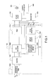
- the ventilation apparatus includes a power conversion unit 10A, a driven circuit 20A, a DC motor 30A, a current-sensing unit 40A, and a microcontroller 50A.
- the power conversion unit 10A receives an AC power voltage Vac and converts the AC power voltage Vac into a DC power voltage Vo.
- the power conversion unit 10A includes an electromagnetic interference filter 102A, a rectifier 104A, a pulse-width modulation integrated circuit (PWM IC) 106A, a DC converter 108A, a filter 110A, an optical coupler 112A, and an error amplifier 114A.
- PWM IC pulse-width modulation integrated circuit
- the electromagnetic interference filter 102A receives the AC power voltage Vac to eliminate noise of the AC power voltage Vac.
- the rectifier 104A is electrically connected to the electromagnetic interference filter 102A to rectify the filtered AC power voltage Vac and output a DC output voltage (not shown).
- the DC converter 108A is electrically connected to the rectifier 104 to receive the DC output voltage and convert energy provided from the AC power voltage Vac to a dc-side load.
- the filter 110A is electrically connected to the DC converter 108A to filter the DC voltage and produce the DC power voltage Vo.
- the PWM IC 106A is electrically connected to the rectifier 104A and the DC converter 108A to output a PWM signal and control power switches (not shown) of the DC converter 108A, thus providing an energy conversion between an input side and an output side of the power conversion unit 10A.
- the optical coupler 112A is electrically connected to the PWM IC 106A to provide signal isolation between the input side and the output side of the power conversion unit 10A.
- the error amplifier 114A is electrically connected to the optical coupler 112A to receive the DC power voltage Vo.
- the DC power voltage Vo is divided through the first resistor R1a, the second resistor R2a to obtain a divided voltage.
- the divided voltage is compared to a reference voltage V1 to produce an error amplifier signal (not shown) and the error amplifier signal is sent to the PWM IC 106A by the optical coupler 112A, thus controlling the DC converter 108A.
- the driven circuit 20A is electrically connected to the power conversion unit 10A to receive the DC power voltage Vo and output a driven voltage (not shown), thus driving the DC motor 30A.
- the DC motor 30A is electrically connected to the driven circuit 20A and driven by the driven voltage outputted from the driven circuit 20A.
- the DC motor 30A is a brushless DC motor, BLDCM.
- the current-sensing unit 40A is electrically connected to driven circuit 20A and the DC motor 30A to sense an output current (not shown) outputted from the DC motor 30A.
- the microcontroller 50A is electrically connected to the current-sensing unit 40A and the driven circuit 20A to receive the output current and the DC power voltage Vo, thus controlling the driven circuit 20A to drive the DC motor 30A.
- Vo V ⁇ 1 ⁇ R ⁇ 1 ⁇ a + R ⁇ 2 ⁇ a R ⁇ 2 ⁇ a
- Fig. 2 is a curve chart of air pressure and air flow of the prior art ventilation apparatus.
- Fig. 2 shows a first curve Cv1 (low-pressure and low-speed curve) and a second curve Cv2 (high-pressure and high-speed curve).
- the curve chart of air pressure and air flow of the ventilation apparatus is shown as the first curve Cv1.
- the curve chart of air pressure and air flow of the ventilation apparatus is shown as the second curve Cv2 when the ventilation apparatus is operated under the high-level DC power voltage Vo.
- the first request energy efficiency
- the second request air flow ratio which is calculated by a third operation point Ps3 and a fourth operation point Ps4 can be achieved when the ventilation apparatus is operated along the second curve CV2.
- the first request cannot be achieved because the air flow exceeds 80 CFM.
- the ventilation apparatus is operated by only using voltage-dividing resistors cannot conform to the requests of Energy Star in US.
- the DC power voltage is compensated and regulated by a voltage compensation unit to conform to requests of power consumption and air flow for the ventilation apparatus.
- An object of the invention is to provide a ventilation apparatus with a feedback compensation control to solve the above-mentioned problems.
- the ventilation apparatus with a two-section feedback compensation control and the ventilation apparatus includes a power conversion unit, a driven circuit, a DC motor, a current-sensing unit, a voltage compensation unit, and a control unit.
- the power conversion unit receives an AC power voltage and converts the AC power voltage into a DC power voltage.
- the driven circuit is electrically connected to the power conversion unit to receive the DC power voltage and output a driven voltage.
- the DC motor is electrically connected to the driven circuit and driven by the driven voltage outputted from the driven circuit.
- the current-sensing unit is electrically connected to driven circuit and the DC motor to sense an output current outputted from the DC motor.
- the voltage compensation unit is electrically connected to the power conversion unit.
- the control unit is electrically connected to the current-sensing unit, the driven circuit, and the voltage compensation unit to receive the output current and produce a threshold current value comparing to the output current.
- control unit When the output current is smaller than the threshold current value, the control unit is configured to produce a DC control signal to control the voltage compensation unit regulating the DC power voltage, thus adjusting speed of the DC motor through the driven circuit.
- Another object of the invention is to provide a ventilation apparatus with a feedback compensation control to solve the above-mentioned problems.
- the ventilation apparatus with a multi-section feedback compensation control and the ventilation apparatus includes a power conversion unit, a driven circuit, a DC motor, a current-sensing unit, a voltage compensation unit, and a control unit.
- the power conversion unit receives an AC power voltage and converts the AC power voltage into a DC power voltage.
- the driven circuit is electrically connected to the power conversion unit to receive the DC power voltage and output a driven voltage.
- the DC motor is electrically connected to the driven circuit and driven by the driven voltage outputted from the driven circuit.
- the current-sensing unit is electrically connected to driven circuit and the DC motor to sense an output current outputted from the DC motor.
- the voltage compensation unit is electrically connected to the power conversion unit.
- the control unit is electrically connected to the current-sensing unit, the driven circuit, and the voltage compensation unit to receive the output current and produce a plurality of threshold current values comparing to the output current.
- the control unit is configured to produce a pulse-width modulation control signal or a digital control signal to control the voltage compensation unit regulating the DC power voltage, thus adjusting speed of the DC motor through the driven circuit according to each threshold current value comparing to the output current.
- Another object of the invention is to provide a method for operating a ventilation apparatus to solve the above-mentioned problems.
- the method is provided to operate the ventilation apparatus with a two-section or a multi-section feedback compensation control and the method includes the following steps: First, a power conversion unit is provided to receive an AC power source and convert the AC power voltage into a DC power voltage. Afterward, a driven circuit is provided to receive the DC power voltage and output a driven voltage to drive a DC motor. Afterward, a current-sensing unit is provided to sense an output current outputted from the DC motor. Afterward, a voltage compensation unit is provided. Finally, a control unit is provided to receive the output current and compare the output current to a threshold current value, thus regulating the DC power voltage by controlling the voltage compensation unit and adjusting speed of the DC motor by the driven circuit.
- Fig. 3 is a circuit diagram of a ventilation apparatus with a two-section feedback compensation control according to a preferred embodiment of the prevent invention.
- the ventilation apparatus includes a power conversion unit 10, a driven circuit 20, a DC motor 30, a current-sensing unit 40, a control unit 50, and a voltage compensation unit 60.
- the power conversion unit 10 receives an AC power voltage Vac and converts the AC power voltage Vac into a DC power voltage Vo.
- the power conversion unit 10 includes an electromagnetic interference filter 102, a rectifier 104, a pulse-width modulation integrated circuit (PWM IC) 106, a DC converter 108, a filter 110, an optical coupler 112, and an error amplifier 114.
- PWM IC pulse-width modulation integrated circuit
- the electromagnetic interference filter 102 receives the AC power voltage Vac to eliminate noise of the AC power voltage Vac.
- the rectifier 104 is electrically connected to the electromagnetic interference filter 102 to rectify the filtered AC power voltage Vac and output a DC output voltage (not shown).
- the DC converter 108 is electrically connected to the rectifier 104 to receive the DC output voltage and convert energy provided from the AC power voltage Vac to a dc-side load.
- the filter 110 is electrically connected to the DC converter 108 to filter the DC voltage and produce the DC power voltage Vo.
- the PWM IC 106 is electrically connected to the rectifier 104 and the DC converter 108 to output a PWM signal and control power switches (not shown) of the DC converter 108, thus providing an energy conversion between an input side and an output side of the power conversion unit 10.
- the optical coupler 112 is electrically connected to the PWM IC 106 to provide signal isolation between the input side and the output side of the power conversion unit 10.
- the error amplifier 114 is electrically connected to the optical coupler 112 to receive the DC power voltage Vo.
- the DC power voltage Vo is divided through the first resistor R1, the second resistor R2, and resistors of the voltage compensation unit 60 (detailed description as follows) to obtain a divided voltage.
- the divided voltage is compared to a reference voltage V1 to produce an error amplifier signal (not shown) and the error amplifier signal is sent to the PWM IC 106 by the optical coupler 112, thus controlling the DC converter 108.
- the driven circuit 20 is electrically connected to the power conversion unit 10 to receive the DC power voltage Vo and output a driven voltage (not shown), thus driving the DC motor 30.
- the DC motor 30 is electrically connected to the driven circuit 20 and driven by the driven voltage outputted from the driven circuit 20.
- the DC motor 30 is a brushless DC motor, BLDCM.
- the voltage compensation unit 60 is electrically connected to the power conversion unit 10 to regulate the DC power voltage Vo, thus adjusting speed of the DC motor 30.
- the current-sensing unit 40 is electrically connected to driven circuit 20 and the DC motor 30 to sense an output current (not shown) outputted from the DC motor 30.
- the control unit 50 is electrically connected to the current-sensing unit 40, the driven circuit 20, and the voltage compensation unit 60 to receive the output current and produce a threshold current value (not shown) comparing to the output current, but not limited. Instead of producing the threshold current value, the control unit 50 alternatively produces a threshold voltage value. In addition, the output current can be converted as an output voltage comparing to the threshold voltage value. If the output current is smaller than the threshold current value, the control unit 50 produces a DC control signal Sc to control the voltage compensation unit 60 regulating the DC power voltage Vo, thus adjusting speed of the DC motor 30 through the driven circuit 20. Hence, the DC motor 30 can be operated under different DC power voltage Vo to meet requests of power consumption and air flow.
- the voltage compensation unit 60 has a third resistor R3 and a first switch S1.
- Fig. 4 is a curve chart of air pressure and air flow of the ventilation apparatus with a feedback compensation control according to the prevent invention.
- Fig. 4 shows a first curve Cv1 (low-pressure and low-speed curve) and a second curve Cv2 (high-pressure and high-speed curve).
- the current-sensing unit 40 senses the output current outputted from the DC motor 30 and the output current is used to compare to the threshold current value, which is produced by the control unit 50, by the voltage compensation unit 60.
- the output current can be converted as an output voltage comparing to a threshold voltage value.
- the control unit 50 can be a microcontroller (MCU).
- the control unit 50 produces the DC control signal Sc to turn on the first switch S1.
- the third resistor R3 is loaded so that the third resistor R3 is electrically connected in parallel to the second resistor R2.
- the DC power voltage Vo is regulated (is increased in this embodiment), thus increasing speed of the DC motor 30.
- the ventilation apparatus is originally operated along the first curve Cv1. After the ventilation apparatus is operated at a first switch operation point Px1, the control unit 50 produces the DC control signal Sc to turn on the first switch S1 and introduce the third resistor R3, thus increasing the DC power voltage Vo and speed of the DC motor 30. Afterward, the operation of the ventilation apparatus is changed to along the second curve Cv2 due to increasing speed of the DC motor 30 before the ventilation apparatus is operated at a second switch operation point Px2. That is, the ventilation apparatus is controlled to be operated along the first curve Cv1 after reaching the first switch operation point Px1 and along the second curve Cv2 before reaching the second switch operation point Px2.
- the above-mentioned operation path of the ventilation apparatus is shown as a third curve Cv3, but not limited.
- the first switch operation point Px1 and the second switch operation point Px2 can be predetermined.
- the output current outputted from the DC motor 30 is compared to the threshold current value produced by the control unit 50 to produce the DC control signal Sc, thus regulating the DC power voltage Vo by controlling the voltage compensation unit 60 and adjusting speed of the DC motor 30 by the driven circuit 20. Accordingly, the requests of air pressure and air flow with regard to Energy Star for the ventilation apparatus can be met.
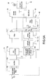
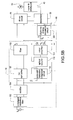
- Fig. 5A and Fig. 5B are circuit diagrams of the ventilation apparatus with a multi-section feedback compensation control according to a first embodiment and a second embodiment of the prevent invention.
- the major difference between this embodiment and the above-mentioned embodiment is that the former is a two-section feedback compensation control.
- the ventilation apparatus includes a power conversion unit 10, a driven circuit 20, a DC motor 30, a current-sensing unit 40, a control unit 50, and a voltage compensation unit 60.
- the power conversion unit 10 receives an AC power voltage Vac and converts the AC power voltage Vac into a DC power voltage Vo.
- the power conversion unit 10 includes an electromagnetic interference filter 102, a rectifier 104, a pulse-width modulation integrated circuit (PWM IC) 106, a DC converter 108, a filter 110, an optical coupler 112, and an error amplifier 114.
- PWM IC pulse-width modulation integrated circuit
- the electromagnetic interference filter 102 receives the AC power voltage Vac to eliminate noise of the AC power voltage Vac.
- the rectifier 104 is electrically connected to the electromagnetic interference filter 102 to rectify the filtered AC power voltage Vac and output a DC output voltage (not shown).
- the DC converter 108 is electrically connected to the rectifier 104 to receive the DC output voltage and convert energy provided from the AC power voltage Vac to a dc-side load.
- the filter 110 is electrically connected to the DC converter 108 to filter the DC voltage and produce the DC power voltage Vo.
- the PWM IC 106 is electrically connected to the rectifier 104 and the DC converter 108 to output a PWM signal and control power switches (not shown) of the DC converter 108, thus providing an energy conversion between an input side and an output side of the power conversion unit 10.
- the optical coupler 112 is electrically connected to the PWM IC 106 to provide signal isolation between the input side and the output side of the power conversion unit 10.
- the error amplifier 114 is electrically connected to the optical coupler 112 to receive the DC power voltage Vo.
- the DC power voltage Vo is divided through the first resistor R1, the second resistor R2, and resistors of the voltage compensation unit 60 (detailed description as follows) to obtain a divided voltage.
- the divided voltage is compared to a reference voltage V1 to produce an error amplifier signal (not shown) and the error amplifier signal is sent to the PWM IC 106, thus controlling the DC converter 108.
- the driven circuit 20 is electrically connected to the power conversion unit 10 to receive the DC power voltage Vo and output a driven voltage (not shown), thus driving the DC motor 30.
- the DC motor 30 is electrically connected to the driven circuit 20 and driven by the driven voltage outputted from the driven circuit 20.
- the DC motor 30 is a brushless DC motor, BLDCM.
- the voltage compensation unit 60 is electrically connected to the power conversion unit 10 to regulate the DC power voltage Vo, thus adjusting speed of the DC motor 30.
- the current-sensing unit 40 is electrically connected to driven circuit 20 and the DC motor 30 to sense an output current (not shown) outputted from the DC motor 30.
- the control unit 50 is electrically connected to the current-sensing unit 40, the driven circuit 20, and the voltage compensation unit 60 to receive the output current and produce a plurality of threshold current values (not shown) comparing to the output current, but not limited. Instead of producing the threshold current values, the control unit 50 also produces a plurality of threshold voltage values. In addition, the output current can be converted as an output voltage comparing to the threshold voltage values.
- the control unit 50 produces a pulse-width modulation control signal Spwm (as shown in Fig. 5A ) or a digital control signal Sd (as shown in Fig.
- the DC motor 30 can be operated under different DC power voltage Vo to meet requests of power consumption and air flow.
- the voltage compensation unit 60 has a fourth resistor R4 and a filter circuit 602.
- the voltage compensation unit 60 has a fourth resistor R4 and a digital-to-analog conversion circuit 604.
- the current-sensing unit 40 senses the output current outputted from the DC motor 30 and the output current is used to compare to the threshold current value, which is produced by the control unit 50, by the voltage compensation unit 60.
- the output current can be converted as an output voltage comparing to a threshold voltage value.
- the control unit 50 can be a microcontroller (MCU).
- the filter circuit 602 filters the PWM control signal Spwm and produces a compensation voltage V2 when the control unit 50 produces the PWM control signal Spwm.
- a voltage level of the compensation voltage V2 can be adjusted by controlling a duty cycle of the PWM control signal Spwm by the control unit 50.
- a new equivalent resistance is formed due to in-parallel connection of the fourth resistor R4 and the second resistor R2 to regulate (to increase in this embodiment) the DC power voltage Vo, thus increasing speed of the DC motor 30.
- the digital-to-analog conversion circuit 604 provides a digital-to-analog operation to the digital control signal Sd and produces a compensation voltage V2 when the control unit 50 produces the digital control signal Sd.
- a voltage level of the compensation voltage V2 can be adjusted by controlling bit values of the digital control signal Sd by the control unit 50.
- a new equivalent resistance is formed due to in-parallel connection of the fourth resistor R4 and the second resistor R2 to regulate (to increase in this embodiment) the DC power voltage Vo, thus increasing speed of the DC motor 30.
- the ventilation apparatus can provide a multi-section feedback compensation control as the two above-mentioned embodiments. That is, the multi-section feedback compensation control can be implemented by controlling the duty cycle of the PWM control signal Spwm or controlling bit values of the digital control signal Sd according to different requests of air pressure and air flow.
- different switch operation points are predetermined to achieve the multi-section feedback compensation control. However, only two switch operation points need to be predetermined for the two-section feedback compensation control. After predetermining the switch operation points, the output current outputted from the DC motor 30 is sensed by the current-sensing unit 40 to compare to the threshold current values produced by the control unit 50, thus producing the PWM control signal Spwm or the digital control signal Sd.
- the PWM control signal Spwm or the digital control signal Sd are received by the filter circuit 602 or the digital-to-analog conversion circuit 604, respectively, to output the compensation voltage V2, thus introducing the fourth resistor R4 to form the new equivalent resistance.
- the DC power voltage Vo is regulated to adjust speed of the DC motor 30 by the driven circuit 20. Accordingly, the requests of air pressure and air flow with regard to Energy Star for the ventilation apparatus can be met.
- Fig. 6 is a flowchart of a method for operating a ventilation apparatus with feedback compensation control according to the present invention.
- the method is provided to operate a ventilation apparatus with a two-section or a multi-section feedback compensation control.
- the method includes following steps: First, a power conversion unit is provided to receive an AC power source and convert the AC power voltage into a DC power voltage (S100).
- the DC motor is a brushless DC motor, BLDCM.
- a driven circuit is provided to receive the DC power voltage and output a driven voltage to drive a DC motor (S200).
- a current-sensing unit is provided to sense an output current outputted from the DC motor (S300).
- a voltage compensation unit is provided (S400).
- the voltage compensation unit has a resistor and a switch component.
- the voltage compensation unit has a resistor and a filter circuit or has a resistor and a digital-to-analog conversion circuit in different embodiments.
- a control unit is provided to receive the output current and comparing the output current to a threshold current value, thus regulating the DC power voltage by the voltage compensation unit and adjusting speed of the DC motor (S500).
- the control unit 50 can be a microcontroller (MCU).
- step S500 the control unit produces a threshold current value to compare to the output current if the output current is smaller than the threshold current value.
- the control unit produces a DC control signal to turn on the switch component to introduce the resistor, thus regulating the DC power voltage by controlling the voltage compensation unit and adjusting speed of the DC motor by the driven circuit.
- the two-section feedback compensation control is implemented to meet requests of power consumption and air flow when the DC motor is operated under different DC power voltage.
- step S500 the control unit produces a plurality of threshold current values to compare to the output current. Also, the control unit produces a PWM control signal according to each threshold current value comparing to the output current, thus controlling the voltage compensation unit to regulate the DC power voltage and adjusting speed of the DC motor by the driven circuit. Accordingly, the multi-section feedback compensation control is implemented to meet requests of power consumption and air flow when the DC motor is operated under different DC power voltage.
- step S500 the control unit produces a plurality of threshold current values to compare to the output current. Also, the control unit produces a digital control signal according to each threshold current value comparing to the output current, thus controlling the voltage compensation unit to regulate the DC power voltage and adjusting speed of the DC motor by the driven circuit. Accordingly, the multi-section feedback compensation control is implemented to meet requests of power consumption and air flow when the DC motor is operated under different DC power voltage.
Landscapes
- Engineering & Computer Science (AREA)
- Power Engineering (AREA)
- Physics & Mathematics (AREA)
- Fluid Mechanics (AREA)
- Chemical & Material Sciences (AREA)
- Combustion & Propulsion (AREA)
- Mechanical Engineering (AREA)
- General Engineering & Computer Science (AREA)
- Control Of Motors That Do Not Use Commutators (AREA)
- Control Of Electric Motors In General (AREA)
- Control Of Direct Current Motors (AREA)
Abstract
Description
- The present invention relates generally to a ventilation apparatus and a method for operating the same, and more particularly to a ventilation apparatus with feedback compensation control and a method for operating the same.
- A traditional home ventilation apparatus, such as an air interchanging fan, is usually involved a shaded-pole motor or a capacitor motor. Also, operation efficiency of the shaded-pole or capacitor ventilation apparatus is typically about 0.8 CFM/Watt to 5.0 CFM/Watt. Because the request of operation efficiency for Energy Star in US has to up to 2.8 CMF/Watt, a brushless DC motor (BLDCM) is now used most widely in the home ventilation apparatus.
- BLDCM has the advantages, such as simple structure, ruggedness, free maintains, and small size, as well as the properties are similar to the DC motor. In addition, BLDCM is driven without exciting current because the rotor thereof is composed of permanent magnetic material to produce lower rotation inertia. Accordingly, BLDCMs are widely applied in precision machineries, automatic control applications, consumer electronics, and computer peripherals.
- Although BLDCMs are used to significantly improve operation efficiency up to 6 CFM/Watt to 12 CFM/Watt, the maximum air flow thereof is reduced. Even if the air flow is increased, power consumption of the ventilation apparatus is correspondingly increased. Both the above-mentioned conditions can not conform to the requests for Energy Star in US.
- Reference is made to
Fig. 1 which is a circuit diagram of a prior art ventilation apparatus. The ventilation apparatus includes apower conversion unit 10A, a drivencircuit 20A, aDC motor 30A, a current-sensing unit 40A, and amicrocontroller 50A. Thepower conversion unit 10A receives an AC power voltage Vac and converts the AC power voltage Vac into a DC power voltage Vo. Thepower conversion unit 10A includes anelectromagnetic interference filter 102A, arectifier 104A, a pulse-width modulation integrated circuit (PWM IC) 106A, aDC converter 108A, afilter 110A, anoptical coupler 112A, and anerror amplifier 114A. - The
electromagnetic interference filter 102A receives the AC power voltage Vac to eliminate noise of the AC power voltage Vac. Therectifier 104A is electrically connected to theelectromagnetic interference filter 102A to rectify the filtered AC power voltage Vac and output a DC output voltage (not shown). TheDC converter 108A is electrically connected to therectifier 104 to receive the DC output voltage and convert energy provided from the AC power voltage Vac to a dc-side load. Thefilter 110A is electrically connected to theDC converter 108A to filter the DC voltage and produce the DC power voltage Vo. The PWM IC 106A is electrically connected to therectifier 104A and theDC converter 108A to output a PWM signal and control power switches (not shown) of theDC converter 108A, thus providing an energy conversion between an input side and an output side of thepower conversion unit 10A. Theoptical coupler 112A is electrically connected to the PWM IC 106A to provide signal isolation between the input side and the output side of thepower conversion unit 10A. Theerror amplifier 114A is electrically connected to theoptical coupler 112A to receive the DC power voltage Vo. The DC power voltage Vo is divided through the first resistor R1a, the second resistor R2a to obtain a divided voltage. The divided voltage is compared to a reference voltage V1 to produce an error amplifier signal (not shown) and the error amplifier signal is sent to thePWM IC 106A by theoptical coupler 112A, thus controlling theDC converter 108A. - The driven
circuit 20A is electrically connected to thepower conversion unit 10A to receive the DC power voltage Vo and output a driven voltage (not shown), thus driving theDC motor 30A. TheDC motor 30A is electrically connected to the drivencircuit 20A and driven by the driven voltage outputted from the drivencircuit 20A. In particular, theDC motor 30A is a brushless DC motor, BLDCM. The current-sensing unit 40A is electrically connected to drivencircuit 20A and theDC motor 30A to sense an output current (not shown) outputted from theDC motor 30A. Themicrocontroller 50A is electrically connected to the current-sensing unit 40A and the drivencircuit 20A to receive the output current and the DC power voltage Vo, thus controlling the drivencircuit 20A to drive theDC motor 30A. - For controlling the ventilation apparatus by using voltage-dividing resistors, due to

- Hence, the DC power voltage Vo is fixed when the first resistor R1a and the second resistor R2a are fixed, and the DC power voltage Vo is equal to

- Reference is made to
Fig. 2 which is a curve chart of air pressure and air flow of the prior art ventilation apparatus.Fig. 2 shows a first curve Cv1 (low-pressure and low-speed curve) and a second curve Cv2 (high-pressure and high-speed curve). When the ventilation apparatus is operated under the low-level DC power voltage Vo, the curve chart of air pressure and air flow of the ventilation apparatus is shown as the first curve Cv1. Similarly, the curve chart of air pressure and air flow of the ventilation apparatus is shown as the second curve Cv2 when the ventilation apparatus is operated under the high-level DC power voltage Vo. - Requests of power consumption and air flow for the ventilation apparatus are regulated by
- Energy Star in US as follows:
- 1. The energy efficiency needs to exceed 2.8 CFM/Watt based on 0.1 inch-H2O and 80 CFM; and
- 2. A ratio between air flow based on 0.25 inch-H2O and that based on 0.1 inch-H2O needs to exceed 60%.
- When the ventilation apparatus is operated along the first curve Cv1, the first request (energy efficiency) can be achieved. However, the second request cannot be achieved because a ratio between air flow based on 0.25 inch-H2O and that based on 0.1 inch-H2O is only 25% (20/80=25%) which is calculated by a first operation point Ps1 and a second operation point Ps2. Furthermore, the second request (air flow ratio which is calculated by a third operation point Ps3 and a fourth operation point Ps4) can be achieved when the ventilation apparatus is operated along the second curve CV2. However, the first request cannot be achieved because the air flow exceeds 80 CFM.
- Hence, the ventilation apparatus is operated by only using voltage-dividing resistors cannot conform to the requests of Energy Star in US.
- Accordingly, it is desirable to provide a ventilation apparatus with a feedback compensation control and a method for operating the same. The DC power voltage is compensated and regulated by a voltage compensation unit to conform to requests of power consumption and air flow for the ventilation apparatus.
- An object of the invention is to provide a ventilation apparatus with a feedback compensation control to solve the above-mentioned problems.
- The ventilation apparatus with a two-section feedback compensation control and the ventilation apparatus includes a power conversion unit, a driven circuit, a DC motor, a current-sensing unit, a voltage compensation unit, and a control unit.
- The power conversion unit receives an AC power voltage and converts the AC power voltage into a DC power voltage. The driven circuit is electrically connected to the power conversion unit to receive the DC power voltage and output a driven voltage. The DC motor is electrically connected to the driven circuit and driven by the driven voltage outputted from the driven circuit. The current-sensing unit is electrically connected to driven circuit and the DC motor to sense an output current outputted from the DC motor. The voltage compensation unit is electrically connected to the power conversion unit. The control unit is electrically connected to the current-sensing unit, the driven circuit, and the voltage compensation unit to receive the output current and produce a threshold current value comparing to the output current.
- When the output current is smaller than the threshold current value, the control unit is configured to produce a DC control signal to control the voltage compensation unit regulating the DC power voltage, thus adjusting speed of the DC motor through the driven circuit.
- Another object of the invention is to provide a ventilation apparatus with a feedback compensation control to solve the above-mentioned problems.
- The ventilation apparatus with a multi-section feedback compensation control and the ventilation apparatus includes a power conversion unit, a driven circuit, a DC motor, a current-sensing unit, a voltage compensation unit, and a control unit.
- The power conversion unit receives an AC power voltage and converts the AC power voltage into a DC power voltage. The driven circuit is electrically connected to the power conversion unit to receive the DC power voltage and output a driven voltage. The DC motor is electrically connected to the driven circuit and driven by the driven voltage outputted from the driven circuit. The current-sensing unit is electrically connected to driven circuit and the DC motor to sense an output current outputted from the DC motor. The voltage compensation unit is electrically connected to the power conversion unit. The control unit is electrically connected to the current-sensing unit, the driven circuit, and the voltage compensation unit to receive the output current and produce a plurality of threshold current values comparing to the output current.
- The control unit is configured to produce a pulse-width modulation control signal or a digital control signal to control the voltage compensation unit regulating the DC power voltage, thus adjusting speed of the DC motor through the driven circuit according to each threshold current value comparing to the output current.
- Another object of the invention is to provide a method for operating a ventilation apparatus to solve the above-mentioned problems.
- The method is provided to operate the ventilation apparatus with a two-section or a multi-section feedback compensation control and the method includes the following steps: First, a power conversion unit is provided to receive an AC power source and convert the AC power voltage into a DC power voltage. Afterward, a driven circuit is provided to receive the DC power voltage and output a driven voltage to drive a DC motor. Afterward, a current-sensing unit is provided to sense an output current outputted from the DC motor. Afterward, a voltage compensation unit is provided. Finally, a control unit is provided to receive the output current and compare the output current to a threshold current value, thus regulating the DC power voltage by controlling the voltage compensation unit and adjusting speed of the DC motor by the driven circuit.
- It is to be understood that both the foregoing general description and the following detailed description are exemplary, and are intended to provide further explanation of the invention as claimed. Other advantages and features of the invention will be apparent from the following description, drawings and claims.
- The features of the invention believed to be novel are set forth with particularity in the appended claims. The invention itself, however, may be best understood by reference to the following detailed description of the invention, which describes an exemplary embodiment of the invention, taken in conjunction with the accompanying drawings, in which:
-
Fig. 1 is a circuit diagram of a prior art ventilation apparatus; -
Fig. 2 is a curve chart of air pressure and air flow of the prior art ventilation apparatus; -
Fig. 3 is a circuit diagram of a ventilation apparatus with a two-section feedback compensation control according to a preferred embodiment of the prevent invention; -
Fig. 4 is a curve chart of air pressure and air flow of the ventilation apparatus with a feedback compensation control according to the prevent invention; -
Fig. 5A is a circuit diagram of a ventilation apparatus with a multi-section feedback compensation control according to a first embodiment of the prevent invention; -
Fig. 5B is a circuit diagram of a ventilation apparatus with a multi-section feedback compensation control according to a second embodiment of the prevent invention; and -
Fig. 6 is a flowchart of a method for operating a ventilation apparatus with feedback compensation control according to the present invention. - Reference will now be made to the drawing figures to describe the present invention in detail.
- Reference is made to
Fig. 3 which is a circuit diagram of a ventilation apparatus with a two-section feedback compensation control according to a preferred embodiment of the prevent invention. The ventilation apparatus includes apower conversion unit 10, a drivencircuit 20, aDC motor 30, a current-sensingunit 40, acontrol unit 50, and avoltage compensation unit 60. - The
power conversion unit 10 receives an AC power voltage Vac and converts the AC power voltage Vac into a DC power voltage Vo. Thepower conversion unit 10 includes anelectromagnetic interference filter 102, arectifier 104, a pulse-width modulation integrated circuit (PWM IC) 106, aDC converter 108, afilter 110, anoptical coupler 112, and anerror amplifier 114. - The
electromagnetic interference filter 102 receives the AC power voltage Vac to eliminate noise of the AC power voltage Vac. Therectifier 104 is electrically connected to theelectromagnetic interference filter 102 to rectify the filtered AC power voltage Vac and output a DC output voltage (not shown). TheDC converter 108 is electrically connected to therectifier 104 to receive the DC output voltage and convert energy provided from the AC power voltage Vac to a dc-side load. Thefilter 110 is electrically connected to theDC converter 108 to filter the DC voltage and produce the DC power voltage Vo. ThePWM IC 106 is electrically connected to therectifier 104 and theDC converter 108 to output a PWM signal and control power switches (not shown) of theDC converter 108, thus providing an energy conversion between an input side and an output side of thepower conversion unit 10. Theoptical coupler 112 is electrically connected to thePWM IC 106 to provide signal isolation between the input side and the output side of thepower conversion unit 10. Theerror amplifier 114 is electrically connected to theoptical coupler 112 to receive the DC power voltage Vo. The DC power voltage Vo is divided through the first resistor R1, the second resistor R2, and resistors of the voltage compensation unit 60 (detailed description as follows) to obtain a divided voltage. The divided voltage is compared to a reference voltage V1 to produce an error amplifier signal (not shown) and the error amplifier signal is sent to thePWM IC 106 by theoptical coupler 112, thus controlling theDC converter 108. - The driven
circuit 20 is electrically connected to thepower conversion unit 10 to receive the DC power voltage Vo and output a driven voltage (not shown), thus driving theDC motor 30. - The
DC motor 30 is electrically connected to the drivencircuit 20 and driven by the driven voltage outputted from the drivencircuit 20. In particular, theDC motor 30 is a brushless DC motor, BLDCM. Thevoltage compensation unit 60 is electrically connected to thepower conversion unit 10 to regulate the DC power voltage Vo, thus adjusting speed of theDC motor 30. - The current-sensing
unit 40 is electrically connected to drivencircuit 20 and theDC motor 30 to sense an output current (not shown) outputted from theDC motor 30. Thecontrol unit 50 is electrically connected to the current-sensingunit 40, the drivencircuit 20, and thevoltage compensation unit 60 to receive the output current and produce a threshold current value (not shown) comparing to the output current, but not limited. Instead of producing the threshold current value, thecontrol unit 50 alternatively produces a threshold voltage value. In addition, the output current can be converted as an output voltage comparing to the threshold voltage value. If the output current is smaller than the threshold current value, thecontrol unit 50 produces a DC control signal Sc to control thevoltage compensation unit 60 regulating the DC power voltage Vo, thus adjusting speed of theDC motor 30 through the drivencircuit 20. Hence, theDC motor 30 can be operated under different DC power voltage Vo to meet requests of power consumption and air flow. - The detailed operation of the ventilation apparatus with the two-section feedback compensation control is described as follows. In this embodiment, the
voltage compensation unit 60 has a third resistor R3 and a first switch S1. Reference is made toFig. 4 which is a curve chart of air pressure and air flow of the ventilation apparatus with a feedback compensation control according to the prevent invention.Fig. 4 shows a first curve Cv1 (low-pressure and low-speed curve) and a second curve Cv2 (high-pressure and high-speed curve). The current-sensingunit 40 senses the output current outputted from theDC motor 30 and the output current is used to compare to the threshold current value, which is produced by thecontrol unit 50, by thevoltage compensation unit 60. Alternatively, the output current can be converted as an output voltage comparing to a threshold voltage value. In particular, thecontrol unit 50 can be a microcontroller (MCU). - If the output current is smaller than the threshold current value, the
control unit 50 produces the DC control signal Sc to turn on the first switch S1. Hence, the third resistor R3 is loaded so that the third resistor R3 is electrically connected in parallel to the second resistor R2. Based on an equivalent resistance due to introduction of the third resistor R3, the DC power voltage Vo is regulated (is increased in this embodiment), thus increasing speed of theDC motor 30. - Accordingly, the DC power voltage Vo is:

- The ventilation apparatus is originally operated along the first curve Cv1. After the ventilation apparatus is operated at a first switch operation point Px1, the
control unit 50 produces the DC control signal Sc to turn on the first switch S1 and introduce the third resistor R3, thus increasing the DC power voltage Vo and speed of theDC motor 30. Afterward, the operation of the ventilation apparatus is changed to along the second curve Cv2 due to increasing speed of theDC motor 30 before the ventilation apparatus is operated at a second switch operation point Px2. That is, the ventilation apparatus is controlled to be operated along the first curve Cv1 after reaching the first switch operation point Px1 and along the second curve Cv2 before reaching the second switch operation point Px2. The above-mentioned operation path of the ventilation apparatus is shown as a third curve Cv3, but not limited. In particular, the first switch operation point Px1 and the second switch operation point Px2 can be predetermined. The output current outputted from theDC motor 30 is compared to the threshold current value produced by thecontrol unit 50 to produce the DC control signal Sc, thus regulating the DC power voltage Vo by controlling thevoltage compensation unit 60 and adjusting speed of theDC motor 30 by the drivencircuit 20. Accordingly, the requests of air pressure and air flow with regard to Energy Star for the ventilation apparatus can be met. - Reference is made to
Fig. 5A andFig. 5B which are circuit diagrams of the ventilation apparatus with a multi-section feedback compensation control according to a first embodiment and a second embodiment of the prevent invention. The major difference between this embodiment and the above-mentioned embodiment is that the former is a two-section feedback compensation control. The ventilation apparatus includes apower conversion unit 10, a drivencircuit 20, aDC motor 30, a current-sensingunit 40, acontrol unit 50, and avoltage compensation unit 60. - The
power conversion unit 10 receives an AC power voltage Vac and converts the AC power voltage Vac into a DC power voltage Vo. Thepower conversion unit 10 includes anelectromagnetic interference filter 102, arectifier 104, a pulse-width modulation integrated circuit (PWM IC) 106, aDC converter 108, afilter 110, anoptical coupler 112, and anerror amplifier 114. - The
electromagnetic interference filter 102 receives the AC power voltage Vac to eliminate noise of the AC power voltage Vac. Therectifier 104 is electrically connected to theelectromagnetic interference filter 102 to rectify the filtered AC power voltage Vac and output a DC output voltage (not shown). TheDC converter 108 is electrically connected to therectifier 104 to receive the DC output voltage and convert energy provided from the AC power voltage Vac to a dc-side load. Thefilter 110 is electrically connected to theDC converter 108 to filter the DC voltage and produce the DC power voltage Vo. ThePWM IC 106 is electrically connected to therectifier 104 and theDC converter 108 to output a PWM signal and control power switches (not shown) of theDC converter 108, thus providing an energy conversion between an input side and an output side of thepower conversion unit 10. Theoptical coupler 112 is electrically connected to thePWM IC 106 to provide signal isolation between the input side and the output side of thepower conversion unit 10. Theerror amplifier 114 is electrically connected to theoptical coupler 112 to receive the DC power voltage Vo. The DC power voltage Vo is divided through the first resistor R1, the second resistor R2, and resistors of the voltage compensation unit 60 (detailed description as follows) to obtain a divided voltage. The divided voltage is compared to a reference voltage V1 to produce an error amplifier signal (not shown) and the error amplifier signal is sent to thePWM IC 106, thus controlling theDC converter 108. - The driven
circuit 20 is electrically connected to thepower conversion unit 10 to receive the DC power voltage Vo and output a driven voltage (not shown), thus driving theDC motor 30. - The
DC motor 30 is electrically connected to the drivencircuit 20 and driven by the driven voltage outputted from the drivencircuit 20. In particular, theDC motor 30 is a brushless DC motor, BLDCM. Thevoltage compensation unit 60 is electrically connected to thepower conversion unit 10 to regulate the DC power voltage Vo, thus adjusting speed of theDC motor 30. - The current-sensing
unit 40 is electrically connected to drivencircuit 20 and theDC motor 30 to sense an output current (not shown) outputted from theDC motor 30. Thecontrol unit 50 is electrically connected to the current-sensingunit 40, the drivencircuit 20, and thevoltage compensation unit 60 to receive the output current and produce a plurality of threshold current values (not shown) comparing to the output current, but not limited. Instead of producing the threshold current values, thecontrol unit 50 also produces a plurality of threshold voltage values. In addition, the output current can be converted as an output voltage comparing to the threshold voltage values. Thecontrol unit 50 produces a pulse-width modulation control signal Spwm (as shown inFig. 5A ) or a digital control signal Sd (as shown inFig. 5B ) to control thevoltage compensation unit 60 regulating the DC power voltage Vo, thus adjusting speed of theDC motor 30 through the drivencircuit 20 according to each threshold current value comparing to the output current. Accordingly, theDC motor 30 can be operated under different DC power voltage Vo to meet requests of power consumption and air flow. - The detailed operation of the ventilation apparatus with the multi-section feedback compensation control is described as follows. In the first embodiment (as shown in
Fig. 5A ), thevoltage compensation unit 60 has a fourth resistor R4 and afilter circuit 602. In the second embodiment (as shown inFig. 5B ), thevoltage compensation unit 60 has a fourth resistor R4 and a digital-to-analog conversion circuit 604. The current-sensingunit 40 senses the output current outputted from theDC motor 30 and the output current is used to compare to the threshold current value, which is produced by thecontrol unit 50, by thevoltage compensation unit 60. Alternatively, the output current can be converted as an output voltage comparing to a threshold voltage value. In particular, thecontrol unit 50 can be a microcontroller (MCU). - With regard to the first embodiment, the
filter circuit 602 filters the PWM control signal Spwm and produces a compensation voltage V2 when thecontrol unit 50 produces the PWM control signal Spwm. In particular, a voltage level of the compensation voltage V2 can be adjusted by controlling a duty cycle of the PWM control signal Spwm by thecontrol unit 50. Hence, a new equivalent resistance is formed due to in-parallel connection of the fourth resistor R4 and the second resistor R2 to regulate (to increase in this embodiment) the DC power voltage Vo, thus increasing speed of theDC motor 30. - Accordingly, the DC power voltage Vo is:

- With regard to the second embodiment, the digital-to-
analog conversion circuit 604 provides a digital-to-analog operation to the digital control signal Sd and produces a compensation voltage V2 when thecontrol unit 50 produces the digital control signal Sd. In particular, a voltage level of the compensation voltage V2 can be adjusted by controlling bit values of the digital control signal Sd by thecontrol unit 50. Hence, a new equivalent resistance is formed due to in-parallel connection of the fourth resistor R4 and the second resistor R2 to regulate (to increase in this embodiment) the DC power voltage Vo, thus increasing speed of theDC motor 30. - Accordingly, the DC power voltage Vo is:

- Accordingly, the ventilation apparatus can provide a multi-section feedback compensation control as the two above-mentioned embodiments. That is, the multi-section feedback compensation control can be implemented by controlling the duty cycle of the PWM control signal Spwm or controlling bit values of the digital control signal Sd according to different requests of air pressure and air flow. Especially to deserve to be mentioned, different switch operation points are predetermined to achieve the multi-section feedback compensation control. However, only two switch operation points need to be predetermined for the two-section feedback compensation control. After predetermining the switch operation points, the output current outputted from the
DC motor 30 is sensed by the current-sensingunit 40 to compare to the threshold current values produced by thecontrol unit 50, thus producing the PWM control signal Spwm or the digital control signal Sd. The PWM control signal Spwm or the digital control signal Sd are received by thefilter circuit 602 or the digital-to-analog conversion circuit 604, respectively, to output the compensation voltage V2, thus introducing the fourth resistor R4 to form the new equivalent resistance. Hence, the DC power voltage Vo is regulated to adjust speed of theDC motor 30 by the drivencircuit 20. Accordingly, the requests of air pressure and air flow with regard to Energy Star for the ventilation apparatus can be met. - Reference is made to
Fig. 6 which is a flowchart of a method for operating a ventilation apparatus with feedback compensation control according to the present invention. The method is provided to operate a ventilation apparatus with a two-section or a multi-section feedback compensation control. The method includes following steps: First, a power conversion unit is provided to receive an AC power source and convert the AC power voltage into a DC power voltage (S100). In particular, the DC motor is a brushless DC motor, BLDCM. Afterward, a driven circuit is provided to receive the DC power voltage and output a driven voltage to drive a DC motor (S200). Afterward, a current-sensing unit is provided to sense an output current outputted from the DC motor (S300). Afterward, a voltage compensation unit is provided (S400). In particular, the voltage compensation unit has a resistor and a switch component. In addition, the voltage compensation unit has a resistor and a filter circuit or has a resistor and a digital-to-analog conversion circuit in different embodiments. Finally, a control unit is provided to receive the output current and comparing the output current to a threshold current value, thus regulating the DC power voltage by the voltage compensation unit and adjusting speed of the DC motor (S500). In particular, thecontrol unit 50 can be a microcontroller (MCU). - With regard to the voltage compensation unit having the resistor and the switch component is discussed as follows. In step S500, the control unit produces a threshold current value to compare to the output current if the output current is smaller than the threshold current value. Hence, the control unit produces a DC control signal to turn on the switch component to introduce the resistor, thus regulating the DC power voltage by controlling the voltage compensation unit and adjusting speed of the DC motor by the driven circuit. Accordingly, the two-section feedback compensation control is implemented to meet requests of power consumption and air flow when the DC motor is operated under different DC power voltage.
- Furthermore, with regard to the voltage compensation unit having the resistor and the filter circuit is discussed as follows. In step S500, the control unit produces a plurality of threshold current values to compare to the output current. Also, the control unit produces a PWM control signal according to each threshold current value comparing to the output current, thus controlling the voltage compensation unit to regulate the DC power voltage and adjusting speed of the DC motor by the driven circuit. Accordingly, the multi-section feedback compensation control is implemented to meet requests of power consumption and air flow when the DC motor is operated under different DC power voltage.
- Furthermore, with regard to the voltage compensation unit having the resistor and the digital-to-analog conversion circuit is discussed as follows. In step S500, the control unit produces a plurality of threshold current values to compare to the output current. Also, the control unit produces a digital control signal according to each threshold current value comparing to the output current, thus controlling the voltage compensation unit to regulate the DC power voltage and adjusting speed of the DC motor by the driven circuit. Accordingly, the multi-section feedback compensation control is implemented to meet requests of power consumption and air flow when the DC motor is operated under different DC power voltage.
- In conclusion, the present invention has following advantages:
- 1. The ventilation apparatus, such as an air interchanging fan, can be operated at rated speed and air flow to consume minimum energy and achieve maximum efficiency;
- 2. The feedback compensation control is provided to prevent the ventilation apparatus from reduction of speed because of the increasing wire resistance coil temperature accompanied by the increasing coil temperature of the DC motor;
- 3. More air flow can be obtained based on the feedback compensation control than that based on a non-feedback compensation control; and
- 4. The feedback compensation control is used to regulate one or more feedback starting voltage to implement the two-section or multi-section feedback compensation control.
Claims (15)
- A ventilation apparatus with a multi-section feedback compensation control; the ventilation apparatus comprising:a power conversion unit (10) receiving an AC power voltage (Vac) and converting the AC power voltage (Vac) into a DC power voltage (Vo);a driven circuit (20) electrically connected to the power conversion unit (10) to receive the DC power voltage (Vo) and output a driven voltage;a DC motor (30) electrically connected to the driven circuit (20) and driven by the driven voltage outputted from the driven circuit (20);a current-sensing unit (40) electrically connected to the DC motor (30) and the driven circuit (20) to sense an output current outputted from the DC motor (30);a voltage compensation unit (60) electrically connected to the power conversion unit (10); anda control unit (50) electrically connected to the current-sensing unit (40), the driven circuit (20), and the voltage compensation unit (60) to receive the output current and produce a plurality of threshold current values comparing to the output current;wherein the control unit (50) is configured to produce a pulse-width modulation control signal (Spwm) or a digital control signal (Sd) to control the voltage compensation unit (60) regulating the DC power voltage (Vo), thus adjusting speed of the DC motor (30) through the driven circuit (20) according to each threshold current value comparing to the output current.
- The ventilation apparatus of claim 1, wherein the voltage compensation unit (60) has a resistor (R4) and a filter circuit (602), and the filter circuit (602) provides a filter operation to the pulse-width modulation control signal (Spwm) when the control unit (50) produces the pulse-width modulation control signal (Spwm).
- The ventilation apparatus of claim 1, wherein the voltage compensation unit (60) has a resistor (R4) and a digital-to-analog conversion circuit (604), and the digital-to-analog conversion circuit (604) provides a digital-to-analog conversion operation to the digital control signal (Sd) when the control unit (50) produces the digital control signal (Sd).
- The ventilation apparatus of claim 1, wherein the control unit (50) is configured to control the voltage compensation unit (60) regulating the DC power voltage (Vo) and adjusting speed of the DC motor (30) through the driven circuit (20) by controlling a duty cycle of the pulse-width modulation control signal (Spwm) or controlling bit values of the digital control signal (Sd).
- The ventilation apparatus of claim 1, wherein the control unit (50) is a microcontroller.
- The ventilation apparatus of claim 1, wherein the DC motor (30) is a brushless DC motor.
- A method for operating a ventilation apparatus with a two-section or a multi-section feedback compensation control; steps of operating the ventilation apparatus comprising:(a) providing a power conversion unit (10) for receiving an AC power voltage (Vac) and converting the AC power voltage (Vac) into a DC power voltage (Vo);(b) providing a driven circuit (20) for receiving the DC power voltage (Vo) and outputting a driven voltage to drive a DC motor (30);(c) providing a current-sensing unit (40) for sensing an output current outputted from the DC motor (30);(d) providing a voltage compensation unit (60); and(e) providing a control unit (50) for receiving the output current and comparing the output current to a threshold current value, thus regulating the DC power voltage (Vo) by controlling the voltage compensation unit (60) and adjusting speed of the DC motor (30) by the driven circuit (20).
- The method for operating the ventilation apparatus of claim 7, in the step (e), the control unit (50) produces a DC control signal (Sc) to control the voltage compensation unit (60) regulating the DC power voltage (Vo), thus adjusting speed of the DC motor (30) through the driven circuit (20) when the output current is smaller than the threshold current value.
- The method for operating the ventilation apparatus of claim 7, in the step (e), the control unit (50) produces a pulse-width modulation control signal (Spwm) or a digital control signal (Sc) to control the voltage compensation unit (60) regulating the DC power voltage (Vo), thus adjusting speed of the DC motor (30) through the driven circuit (20) according to each threshold current value comparing to the output current.
- The method for operating the ventilation apparatus of claim 8, wherein the voltage compensation unit (60) has a resistor (R3) and a switch component (S1); and the control unit (50) loads the resistor (R3) by turning on the switch component (S1) through the DC control signal (Sc), thus regulating the DC power voltage (Vo) and adjusting speed of the DC motor (30) through the driven circuit (20).
- The method for operating the ventilation apparatus of claim 9, wherein the voltage compensation unit (60) has a resistor (R4) and a filter circuit (602); the filter circuit (602) provides a filter operation to the pulse-width modulation control signal (Spwm) when the control unit (50) produces the pulse-width modulation control signal (Spwm).
- The method for operating the ventilation apparatus of claim 9, wherein the voltage compensation unit (60) has a resistor (R4) and a digital-to-analog conversion circuit (604); the digital-to-analog conversion circuit (604) provides a digital-to-analog conversion operation to the digital control signal (Sd) when the control unit (50) produces the digital control signal (Sd).
- The method for operating the ventilation apparatus of claim 9, wherein the control unit (50) controls the voltage compensation unit (60) regulating the DC power voltage (Vo) and adjusting speed of the DC motor (30) through the driven circuit (20) by controlling a duty cycle of the pulse-width modulation control signal (Spwm) or controlling bit values of the digital control signal (Sd).
- The method for operating the ventilation apparatus of claim 7, wherein the control unit (50) is a microcontroller.
- The method for operating the ventilation apparatus of claim 7, wherein the DC motor (30) is a brushless DC motor.
Applications Claiming Priority (1)
| Application Number | Priority Date | Filing Date | Title |
|---|---|---|---|
| TW100117883A TWI435530B (en) | 2011-05-23 | 2011-05-23 | Ventilation apparatus with feedback compensation control and method for operating the same |
Publications (3)
| Publication Number | Publication Date |
|---|---|
| EP2528223A2 true EP2528223A2 (en) | 2012-11-28 |
| EP2528223A3 EP2528223A3 (en) | 2013-10-30 |
| EP2528223B1 EP2528223B1 (en) | 2017-07-05 |
Family
ID=46466041
Family Applications (1)
| Application Number | Title | Priority Date | Filing Date |
|---|---|---|---|
| EP12003991.2A Not-in-force EP2528223B1 (en) | 2011-05-23 | 2012-05-22 | Ventilation apparatus with feedback compensation control and method for operating the same |
Country Status (3)
| Country | Link |
|---|---|
| US (1) | US8749185B2 (en) |
| EP (1) | EP2528223B1 (en) |
| TW (1) | TWI435530B (en) |
Cited By (2)
| Publication number | Priority date | Publication date | Assignee | Title |
|---|---|---|---|---|
| CN104566808A (en) * | 2014-12-24 | 2015-04-29 | 珠海格力电器股份有限公司 | Air conditioner control method and device |
| CN110173806A (en) * | 2019-05-10 | 2019-08-27 | 广东美的制冷设备有限公司 | Air conditioner and its control method and device |
Families Citing this family (2)
| Publication number | Priority date | Publication date | Assignee | Title |
|---|---|---|---|---|
| TWI555324B (en) * | 2014-05-15 | 2016-10-21 | Dyna Rechi Co Ltd | DC brushless motor control system for AC power supply |
| JP6305309B2 (en) * | 2014-10-16 | 2018-04-04 | リンナイ株式会社 | Ventilation equipment |
Family Cites Families (6)
| Publication number | Priority date | Publication date | Assignee | Title |
|---|---|---|---|---|
| EP1039139B1 (en) | 1999-03-23 | 2004-05-26 | ebm-papst Mulfingen GmbH & Co.KG | Blower with characteristic curve |
| US7468595B2 (en) * | 2005-07-26 | 2008-12-23 | Eaton Corporation | System and method of controlling the start-up of an adjustable speed motor drive based sinusoidal output power conditioner |
| TWI301355B (en) | 2005-08-24 | 2008-09-21 | Delta Electronics Inc | Current control device and method |
| JP4444195B2 (en) | 2005-10-04 | 2010-03-31 | パナソニック株式会社 | Blower and electric device equipped with the same |
| KR20080058070A (en) * | 2006-12-21 | 2008-06-25 | 삼성전자주식회사 | BCD motor control method and device |
| KR100946719B1 (en) | 2007-11-28 | 2010-03-12 | 영 춘 정 | Multi-programmable constant flow control device of variable speed non-commutator motor |
-
2011
- 2011-05-23 TW TW100117883A patent/TWI435530B/en active
- 2011-09-30 US US13/250,273 patent/US8749185B2/en active Active
-
2012
- 2012-05-22 EP EP12003991.2A patent/EP2528223B1/en not_active Not-in-force
Non-Patent Citations (1)
| Title |
|---|
| None |
Cited By (2)
| Publication number | Priority date | Publication date | Assignee | Title |
|---|---|---|---|---|
| CN104566808A (en) * | 2014-12-24 | 2015-04-29 | 珠海格力电器股份有限公司 | Air conditioner control method and device |
| CN110173806A (en) * | 2019-05-10 | 2019-08-27 | 广东美的制冷设备有限公司 | Air conditioner and its control method and device |
Also Published As
| Publication number | Publication date |
|---|---|
| TW201249093A (en) | 2012-12-01 |
| US8749185B2 (en) | 2014-06-10 |
| US20120299525A1 (en) | 2012-11-29 |
| TWI435530B (en) | 2014-04-21 |
| EP2528223A3 (en) | 2013-10-30 |
| EP2528223B1 (en) | 2017-07-05 |
Similar Documents
| Publication | Publication Date | Title |
|---|---|---|
| EP2096742B1 (en) | Power factor correction circuit for air conditioning equipment | |
| JP3308993B2 (en) | Electric motor driving device and air conditioner using the same | |
| JP5809833B2 (en) | Motor drive device and motor device using the same | |
| US8988899B2 (en) | Switching regulator device | |
| JP2008061452A (en) | Power supply device and operation control method thereof | |
| US20160197566A1 (en) | Method and apparatus to control a single-phase induction motor | |
| EP2528223B1 (en) | Ventilation apparatus with feedback compensation control and method for operating the same | |
| US12206329B2 (en) | DC/DC converter using partial resonance and control method thereof | |
| US20050146297A1 (en) | Efficiency optimization control for permanent magnet motor drive | |
| CN102801307A (en) | Power converter and control method thereof | |
| US8421390B2 (en) | Fan motor control device | |
| CN102307015B (en) | Switch type power supply device and transient peak current compensation method thereof | |
| KR101075222B1 (en) | Apparatus and method of power factor correction | |
| US20100134054A1 (en) | Fan and motor control device | |
| US8138710B2 (en) | Power drive of electric motor | |
| JP2004260871A (en) | Power supply | |
| CN102801375B (en) | Ventilation device with feedback compensation control and operation method thereof | |
| US20230155500A1 (en) | Load dependent frequency shift boost converter | |
| US8342812B2 (en) | Variable speed air compressing system having AC and DC power sources | |
| JPH1189283A (en) | Motor control device and air conditioner using the same | |
| JP7490089B2 (en) | Air conditioners | |
| US20030052629A1 (en) | Control circuit for a DC brushless motor | |
| JP2005065449A (en) | Motor control device | |
| KR100725868B1 (en) | Maximum torque control system of electric motor | |
| US20070024224A1 (en) | kW-based torque control for AC motors |
Legal Events
| Date | Code | Title | Description |
|---|---|---|---|
| PUAI | Public reference made under article 153(3) epc to a published international application that has entered the european phase |
Free format text: ORIGINAL CODE: 0009012 |
|
| AK | Designated contracting states |
Kind code of ref document: A2 Designated state(s): AL AT BE BG CH CY CZ DE DK EE ES FI FR GB GR HR HU IE IS IT LI LT LU LV MC MK MT NL NO PL PT RO RS SE SI SK SM TR |
|
| AX | Request for extension of the european patent |
Extension state: BA ME |
|
| PUAL | Search report despatched |
Free format text: ORIGINAL CODE: 0009013 |
|
| AK | Designated contracting states |
Kind code of ref document: A3 Designated state(s): AL AT BE BG CH CY CZ DE DK EE ES FI FR GB GR HR HU IE IS IT LI LT LU LV MC MK MT NL NO PL PT RO RS SE SI SK SM TR |
|
| AX | Request for extension of the european patent |
Extension state: BA ME |
|
| RIC1 | Information provided on ipc code assigned before grant |
Ipc: H02P 7/29 20060101AFI20130923BHEP Ipc: H02P 29/00 20060101ALI20130923BHEP |
|
| 17P | Request for examination filed |
Effective date: 20140429 |
|
| RBV | Designated contracting states (corrected) |
Designated state(s): AL AT BE BG CH CY CZ DE DK EE ES FI FR GB GR HR HU IE IS IT LI LT LU LV MC MK MT NL NO PL PT RO RS SE SI SK SM TR |
|
| GRAP | Despatch of communication of intention to grant a patent |
Free format text: ORIGINAL CODE: EPIDOSNIGR1 |
|
| RIC1 | Information provided on ipc code assigned before grant |
Ipc: H02P 7/29 20160101AFI20170119BHEP Ipc: H02P 29/00 20160101ALI20170119BHEP Ipc: F24F 11/00 20060101ALI20170119BHEP |
|
| INTG | Intention to grant announced |
Effective date: 20170213 |
|
| GRAS | Grant fee paid |
Free format text: ORIGINAL CODE: EPIDOSNIGR3 |
|
| GRAA | (expected) grant |
Free format text: ORIGINAL CODE: 0009210 |
|
| AK | Designated contracting states |
Kind code of ref document: B1 Designated state(s): AL AT BE BG CH CY CZ DE DK EE ES FI FR GB GR HR HU IE IS IT LI LT LU LV MC MK MT NL NO PL PT RO RS SE SI SK SM TR |
|
| REG | Reference to a national code |
Ref country code: GB Ref legal event code: FG4D |
|
| REG | Reference to a national code |
Ref country code: CH Ref legal event code: EP |
|
| REG | Reference to a national code |
Ref country code: AT Ref legal event code: REF Ref document number: 907235 Country of ref document: AT Kind code of ref document: T Effective date: 20170715 |
|
| REG | Reference to a national code |
Ref country code: IE Ref legal event code: FG4D |
|
| REG | Reference to a national code |
Ref country code: DE Ref legal event code: R096 Ref document number: 602012034111 Country of ref document: DE |
|
| REG | Reference to a national code |
Ref country code: NL Ref legal event code: MP Effective date: 20170705 |
|
| REG | Reference to a national code |
Ref country code: AT Ref legal event code: MK05 Ref document number: 907235 Country of ref document: AT Kind code of ref document: T Effective date: 20170705 |
|
| REG | Reference to a national code |
Ref country code: LT Ref legal event code: MG4D |
|
| PG25 | Lapsed in a contracting state [announced via postgrant information from national office to epo] |
Ref country code: LT Free format text: LAPSE BECAUSE OF FAILURE TO SUBMIT A TRANSLATION OF THE DESCRIPTION OR TO PAY THE FEE WITHIN THE PRESCRIBED TIME-LIMIT Effective date: 20170705 Ref country code: FI Free format text: LAPSE BECAUSE OF FAILURE TO SUBMIT A TRANSLATION OF THE DESCRIPTION OR TO PAY THE FEE WITHIN THE PRESCRIBED TIME-LIMIT Effective date: 20170705 Ref country code: NO Free format text: LAPSE BECAUSE OF FAILURE TO SUBMIT A TRANSLATION OF THE DESCRIPTION OR TO PAY THE FEE WITHIN THE PRESCRIBED TIME-LIMIT Effective date: 20171005 Ref country code: HR Free format text: LAPSE BECAUSE OF FAILURE TO SUBMIT A TRANSLATION OF THE DESCRIPTION OR TO PAY THE FEE WITHIN THE PRESCRIBED TIME-LIMIT Effective date: 20170705 Ref country code: NL Free format text: LAPSE BECAUSE OF FAILURE TO SUBMIT A TRANSLATION OF THE DESCRIPTION OR TO PAY THE FEE WITHIN THE PRESCRIBED TIME-LIMIT Effective date: 20170705 Ref country code: AT Free format text: LAPSE BECAUSE OF FAILURE TO SUBMIT A TRANSLATION OF THE DESCRIPTION OR TO PAY THE FEE WITHIN THE PRESCRIBED TIME-LIMIT Effective date: 20170705 Ref country code: SE Free format text: LAPSE BECAUSE OF FAILURE TO SUBMIT A TRANSLATION OF THE DESCRIPTION OR TO PAY THE FEE WITHIN THE PRESCRIBED TIME-LIMIT Effective date: 20170705 |
|
| PG25 | Lapsed in a contracting state [announced via postgrant information from national office to epo] |
Ref country code: PL Free format text: LAPSE BECAUSE OF FAILURE TO SUBMIT A TRANSLATION OF THE DESCRIPTION OR TO PAY THE FEE WITHIN THE PRESCRIBED TIME-LIMIT Effective date: 20170705 Ref country code: RS Free format text: LAPSE BECAUSE OF FAILURE TO SUBMIT A TRANSLATION OF THE DESCRIPTION OR TO PAY THE FEE WITHIN THE PRESCRIBED TIME-LIMIT Effective date: 20170705 Ref country code: BG Free format text: LAPSE BECAUSE OF FAILURE TO SUBMIT A TRANSLATION OF THE DESCRIPTION OR TO PAY THE FEE WITHIN THE PRESCRIBED TIME-LIMIT Effective date: 20171005 Ref country code: GR Free format text: LAPSE BECAUSE OF FAILURE TO SUBMIT A TRANSLATION OF THE DESCRIPTION OR TO PAY THE FEE WITHIN THE PRESCRIBED TIME-LIMIT Effective date: 20171006 Ref country code: ES Free format text: LAPSE BECAUSE OF FAILURE TO SUBMIT A TRANSLATION OF THE DESCRIPTION OR TO PAY THE FEE WITHIN THE PRESCRIBED TIME-LIMIT Effective date: 20170705 Ref country code: LV Free format text: LAPSE BECAUSE OF FAILURE TO SUBMIT A TRANSLATION OF THE DESCRIPTION OR TO PAY THE FEE WITHIN THE PRESCRIBED TIME-LIMIT Effective date: 20170705 Ref country code: IS Free format text: LAPSE BECAUSE OF FAILURE TO SUBMIT A TRANSLATION OF THE DESCRIPTION OR TO PAY THE FEE WITHIN THE PRESCRIBED TIME-LIMIT Effective date: 20171105 |
|
| REG | Reference to a national code |
Ref country code: DE Ref legal event code: R097 Ref document number: 602012034111 Country of ref document: DE |
|
| PG25 | Lapsed in a contracting state [announced via postgrant information from national office to epo] |
Ref country code: CZ Free format text: LAPSE BECAUSE OF FAILURE TO SUBMIT A TRANSLATION OF THE DESCRIPTION OR TO PAY THE FEE WITHIN THE PRESCRIBED TIME-LIMIT Effective date: 20170705 Ref country code: DK Free format text: LAPSE BECAUSE OF FAILURE TO SUBMIT A TRANSLATION OF THE DESCRIPTION OR TO PAY THE FEE WITHIN THE PRESCRIBED TIME-LIMIT Effective date: 20170705 Ref country code: RO Free format text: LAPSE BECAUSE OF FAILURE TO SUBMIT A TRANSLATION OF THE DESCRIPTION OR TO PAY THE FEE WITHIN THE PRESCRIBED TIME-LIMIT Effective date: 20170705 |
|
| PLBE | No opposition filed within time limit |
Free format text: ORIGINAL CODE: 0009261 |
|
| STAA | Information on the status of an ep patent application or granted ep patent |
Free format text: STATUS: NO OPPOSITION FILED WITHIN TIME LIMIT |
|
| REG | Reference to a national code |
Ref country code: FR Ref legal event code: PLFP Year of fee payment: 7 |
|
| PG25 | Lapsed in a contracting state [announced via postgrant information from national office to epo] |
Ref country code: SK Free format text: LAPSE BECAUSE OF FAILURE TO SUBMIT A TRANSLATION OF THE DESCRIPTION OR TO PAY THE FEE WITHIN THE PRESCRIBED TIME-LIMIT Effective date: 20170705 Ref country code: SM Free format text: LAPSE BECAUSE OF FAILURE TO SUBMIT A TRANSLATION OF THE DESCRIPTION OR TO PAY THE FEE WITHIN THE PRESCRIBED TIME-LIMIT Effective date: 20170705 Ref country code: IT Free format text: LAPSE BECAUSE OF FAILURE TO SUBMIT A TRANSLATION OF THE DESCRIPTION OR TO PAY THE FEE WITHIN THE PRESCRIBED TIME-LIMIT Effective date: 20170705 Ref country code: EE Free format text: LAPSE BECAUSE OF FAILURE TO SUBMIT A TRANSLATION OF THE DESCRIPTION OR TO PAY THE FEE WITHIN THE PRESCRIBED TIME-LIMIT Effective date: 20170705 |
|
| 26N | No opposition filed |
Effective date: 20180406 |
|
| PG25 | Lapsed in a contracting state [announced via postgrant information from national office to epo] |
Ref country code: SI Free format text: LAPSE BECAUSE OF FAILURE TO SUBMIT A TRANSLATION OF THE DESCRIPTION OR TO PAY THE FEE WITHIN THE PRESCRIBED TIME-LIMIT Effective date: 20170705 |
|
| REG | Reference to a national code |
Ref country code: CH Ref legal event code: PL |
|
| GBPC | Gb: european patent ceased through non-payment of renewal fee |
Effective date: 20180522 |
|
| REG | Reference to a national code |
Ref country code: BE Ref legal event code: MM Effective date: 20180531 |
|
| PG25 | Lapsed in a contracting state [announced via postgrant information from national office to epo] |
Ref country code: MC Free format text: LAPSE BECAUSE OF FAILURE TO SUBMIT A TRANSLATION OF THE DESCRIPTION OR TO PAY THE FEE WITHIN THE PRESCRIBED TIME-LIMIT Effective date: 20170705 |
|
| REG | Reference to a national code |
Ref country code: IE Ref legal event code: MM4A |
|
| PG25 | Lapsed in a contracting state [announced via postgrant information from national office to epo] |
Ref country code: LI Free format text: LAPSE BECAUSE OF NON-PAYMENT OF DUE FEES Effective date: 20180531 Ref country code: CH Free format text: LAPSE BECAUSE OF NON-PAYMENT OF DUE FEES Effective date: 20180531 |
|
| PG25 | Lapsed in a contracting state [announced via postgrant information from national office to epo] |
Ref country code: LU Free format text: LAPSE BECAUSE OF NON-PAYMENT OF DUE FEES Effective date: 20180522 |
|
| PG25 | Lapsed in a contracting state [announced via postgrant information from national office to epo] |
Ref country code: GB Free format text: LAPSE BECAUSE OF NON-PAYMENT OF DUE FEES Effective date: 20180522 Ref country code: IE Free format text: LAPSE BECAUSE OF NON-PAYMENT OF DUE FEES Effective date: 20180522 |
|
| PG25 | Lapsed in a contracting state [announced via postgrant information from national office to epo] |
Ref country code: BE Free format text: LAPSE BECAUSE OF NON-PAYMENT OF DUE FEES Effective date: 20180531 |
|
| PGFP | Annual fee paid to national office [announced via postgrant information from national office to epo] |
Ref country code: DE Payment date: 20190530 Year of fee payment: 8 |
|
| PGFP | Annual fee paid to national office [announced via postgrant information from national office to epo] |
Ref country code: FR Payment date: 20190527 Year of fee payment: 8 |
|
| PG25 | Lapsed in a contracting state [announced via postgrant information from national office to epo] |
Ref country code: MT Free format text: LAPSE BECAUSE OF NON-PAYMENT OF DUE FEES Effective date: 20180522 |
|
| PG25 | Lapsed in a contracting state [announced via postgrant information from national office to epo] |
Ref country code: TR Free format text: LAPSE BECAUSE OF FAILURE TO SUBMIT A TRANSLATION OF THE DESCRIPTION OR TO PAY THE FEE WITHIN THE PRESCRIBED TIME-LIMIT Effective date: 20170705 |
|
| PG25 | Lapsed in a contracting state [announced via postgrant information from national office to epo] |
Ref country code: PT Free format text: LAPSE BECAUSE OF FAILURE TO SUBMIT A TRANSLATION OF THE DESCRIPTION OR TO PAY THE FEE WITHIN THE PRESCRIBED TIME-LIMIT Effective date: 20170705 Ref country code: HU Free format text: LAPSE BECAUSE OF FAILURE TO SUBMIT A TRANSLATION OF THE DESCRIPTION OR TO PAY THE FEE WITHIN THE PRESCRIBED TIME-LIMIT; INVALID AB INITIO Effective date: 20120522 |
|
| PG25 | Lapsed in a contracting state [announced via postgrant information from national office to epo] |
Ref country code: CY Free format text: LAPSE BECAUSE OF FAILURE TO SUBMIT A TRANSLATION OF THE DESCRIPTION OR TO PAY THE FEE WITHIN THE PRESCRIBED TIME-LIMIT Effective date: 20170705 Ref country code: MK Free format text: LAPSE BECAUSE OF NON-PAYMENT OF DUE FEES Effective date: 20170705 |
|
| PG25 | Lapsed in a contracting state [announced via postgrant information from national office to epo] |
Ref country code: AL Free format text: LAPSE BECAUSE OF FAILURE TO SUBMIT A TRANSLATION OF THE DESCRIPTION OR TO PAY THE FEE WITHIN THE PRESCRIBED TIME-LIMIT Effective date: 20170705 |
|
| REG | Reference to a national code |
Ref country code: DE Ref legal event code: R119 Ref document number: 602012034111 Country of ref document: DE |
|
| PG25 | Lapsed in a contracting state [announced via postgrant information from national office to epo] |
Ref country code: FR Free format text: LAPSE BECAUSE OF NON-PAYMENT OF DUE FEES Effective date: 20200531 |
|
| PG25 | Lapsed in a contracting state [announced via postgrant information from national office to epo] |
Ref country code: DE Free format text: LAPSE BECAUSE OF NON-PAYMENT OF DUE FEES Effective date: 20201201 |