EP2527876A1 - Automatic anisotropy, azimuth and dip determination from upscaled image log data - Google Patents
Automatic anisotropy, azimuth and dip determination from upscaled image log data Download PDFInfo
- Publication number
- EP2527876A1 EP2527876A1 EP12168527A EP12168527A EP2527876A1 EP 2527876 A1 EP2527876 A1 EP 2527876A1 EP 12168527 A EP12168527 A EP 12168527A EP 12168527 A EP12168527 A EP 12168527A EP 2527876 A1 EP2527876 A1 EP 2527876A1
- Authority
- EP
- European Patent Office
- Prior art keywords
- depth
- arbitrary plane
- anisotropy
- borehole
- determining
- Prior art date
- Legal status (The legal status is an assumption and is not a legal conclusion. Google has not performed a legal analysis and makes no representation as to the accuracy of the status listed.)
- Withdrawn
Links
- 238000000034 method Methods 0.000 claims abstract description 69
- 238000005259 measurement Methods 0.000 claims abstract description 38
- 238000001739 density measurement Methods 0.000 claims 1
- 230000008569 process Effects 0.000 description 22
- 230000015572 biosynthetic process Effects 0.000 description 16
- 230000008901 benefit Effects 0.000 description 12
- 238000005481 NMR spectroscopy Methods 0.000 description 6
- 230000035699 permeability Effects 0.000 description 6
- 238000007598 dipping method Methods 0.000 description 5
- 238000005553 drilling Methods 0.000 description 5
- 238000010586 diagram Methods 0.000 description 4
- 229930195733 hydrocarbon Natural products 0.000 description 3
- 150000002430 hydrocarbons Chemical class 0.000 description 3
- 239000011435 rock Substances 0.000 description 3
- 238000012360 testing method Methods 0.000 description 3
- 230000004075 alteration Effects 0.000 description 2
- 238000004458 analytical method Methods 0.000 description 2
- 238000004891 communication Methods 0.000 description 2
- 238000013500 data storage Methods 0.000 description 2
- 238000003475 lamination Methods 0.000 description 2
- 238000012986 modification Methods 0.000 description 2
- 230000004048 modification Effects 0.000 description 2
- 238000012545 processing Methods 0.000 description 2
- 238000011179 visual inspection Methods 0.000 description 2
- UFHFLCQGNIYNRP-UHFFFAOYSA-N Hydrogen Chemical compound [H][H] UFHFLCQGNIYNRP-UHFFFAOYSA-N 0.000 description 1
- 238000004364 calculation method Methods 0.000 description 1
- 230000001066 destructive effect Effects 0.000 description 1
- 238000011161 development Methods 0.000 description 1
- 238000006073 displacement reaction Methods 0.000 description 1
- 230000000694 effects Effects 0.000 description 1
- 238000005516 engineering process Methods 0.000 description 1
- 230000007613 environmental effect Effects 0.000 description 1
- 238000011156 evaluation Methods 0.000 description 1
- 229910052739 hydrogen Inorganic materials 0.000 description 1
- 239000001257 hydrogen Substances 0.000 description 1
- 238000003384 imaging method Methods 0.000 description 1
- 230000005415 magnetization Effects 0.000 description 1
- 238000004519 manufacturing process Methods 0.000 description 1
- 230000006855 networking Effects 0.000 description 1
- 239000003208 petroleum Substances 0.000 description 1
- 230000003068 static effect Effects 0.000 description 1
Images



Classifications
-
- G—PHYSICS
- G01—MEASURING; TESTING
- G01V—GEOPHYSICS; GRAVITATIONAL MEASUREMENTS; DETECTING MASSES OR OBJECTS; TAGS
- G01V3/00—Electric or magnetic prospecting or detecting; Measuring magnetic field characteristics of the earth, e.g. declination, deviation
- G01V3/18—Electric or magnetic prospecting or detecting; Measuring magnetic field characteristics of the earth, e.g. declination, deviation specially adapted for well-logging
-
- G—PHYSICS
- G01—MEASURING; TESTING
- G01N—INVESTIGATING OR ANALYSING MATERIALS BY DETERMINING THEIR CHEMICAL OR PHYSICAL PROPERTIES
- G01N24/00—Investigating or analyzing materials by the use of nuclear magnetic resonance, electron paramagnetic resonance or other spin effects
- G01N24/08—Investigating or analyzing materials by the use of nuclear magnetic resonance, electron paramagnetic resonance or other spin effects by using nuclear magnetic resonance
- G01N24/081—Making measurements of geologic samples, e.g. measurements of moisture, pH, porosity, permeability, tortuosity or viscosity
Definitions
- the present invention relates to methods of determining anisotropy, specifically in a borehole.
- the present invention relates to oilfield operations, and more particularly, to methods and systems for determining anisotropy, dip, and azimuth from image data.
- the geological properties of the formation are important throughout the development of a well.
- the geological properties of the formation can be used to determine if the formation contains hydrocarbons, determine the producibility of the hydrocarbons in the formation, and optimize production from the well.
- Wireline logging and/or logging-while-drilling (LWD) or measurement-while-drilling (MWD) are commonly used to obtain measurements that shed light on the geological properties of a formation. Accordingly, one or more logging tools may be lowered into the borehole and used to obtain measurements as the tools traverse the borehole. These measurements may then be used to estimate a number of desired formation properties.
- NMR nuclear magnetic resonance
- One of the applications of NMR and other logging techniques is the analysis of certain properties of the geological formation.
- properties may include, for example, permeability, porosity, resistivity, diffusivity, or viscosity.
- Anisotropic analysis of properties is particularly useful in reservoir engineering where data or logs obtained through multiple measurements at different locations may be combined in order to characterize each flow interval of the geological area by a single anisotropy, such as permeability anisotropy.
- the process of combining the data obtained through multiple measurements and multiple locations is referred to as "up-scaling". Because the measurement data are typically taken at various scales and use different sample sizes, up-scaling the data can be difficult.
- the measurement data is processed by visual inspection and/or correlation.
- a single anisotropy such as permeability anisotropy obtained for a flow interval, may be used to predict the producibility of the well. It is often necessary to perform well testing before such performance predictions can be made. However, the performance of well testing has become undesirable due to the high economic and environmental costs associated with it.
- the sedimentary portion of the earth's surface is made up of successive layers or beds which do not typically have a constant thickness. These layers often exhibit a certain dip, e.g., an inclination with respect to a horizontal plane.
- the dip angle is the angle between the vertical direction and a line perpendicular to the bedding plane.
- the relative borehole dip is the angle between the borehole and a line perpendicular to the bedding planes.
- the dip of formation layers in a formation penetrated by a borehole may convey important information in petroleum prospecting. For example, such information may be useful for evaluating the chances of obtaining hydrocarbons from a borehole, for establishing the nature of adjacent geological structures and for choosing the location of new boreholes.
- an up-scaling method which honors the petrophysical spatial relationships of the data and can be used to combine different types of data including core data, wireline logs, wireline tester data and well testing to obtain image data anisotropy and the dip angle of the anisotropy.
- the azimuth angle is associated with the dipping plane and is the angle formed by the plane defining the anisotropy with respect to the north axis of the earth.
- Relative azimuth is the angle formed by the anisotropy plane and its intersection to the borehole.
- a method of determining anisotropy in a borehole comprising: obtaining an array of measurements along the borehole; selecting a first depth in the borehole; designating an arbitrary plane oriented with respect to the borehole at the first depth; determining an anisotropy for the first depth with respect to the arbitrary plane; repositioning the arbitrary plane at the first depth; determining an anisotropy for different positions of the arbitrary plane at the first depth; identifying a minimum anisotropy coefficient with respect to the arbitrary plane at the first depth, wherein the minimum anisotropy coefficient is identified based on the anisotropy for different positions of the arbitrary plane; and defining an anisotropy tensor for the first depth.
- a method for determining anisotropy comprising: measuring a desired characteristic along a borehole; wherein the desired characteristic is represented by a plurality of data points along the borehole; identifying a plurality of depth locations in the borehole; selecting one of the plurality of depth locations in the borehole as a first depth location; selecting a first set of data points corresponding to the first depth location; selecting an arbitrary plane oriented with respect to the borehole at the first depth location; determining a first anisotropy for the first depth location with respect to the arbitrary plane; reorienting the arbitrary plane at the first depth location; wherein reorienting the arbitrary plane at the first depth location comprises changing at least one of an azimuth angle and a dip angle of the arbitrary plane; determining a second anisotropy for the first depth location with respect to the arbitrary plane; identifying a minimum anisotropy coefficient for the arbitrary plane at the first depth location; and outputting the minimum aniso
- the present invention relates generally to oilfield operations, and more particularly, to methods and systems for determining anisotropy, dip, and azimuth from image data.
- an array of measurements is first obtained along a borehole using traditional logging tools. Using a portion of this array positioned near a depth location, an up-scaling method is used to determine the anisotropy with respect to the plane.
- the up-scaling methods honor the petrophysical spatial relationships of data and determine the image data anisotropy.
- Anisotropy is a result of thin laminations that may be virtually undetectable using normal logs but may be well within the scale of image logs. These thin laminations may be oriented to anisotropy and the bedding plane. Up scaling methods may determine the anisotropy tensor even when this may not be apparent using pattern matching and visual inspection of the data.
- Figure 1 is a flow diagram of steps of an up-scaling method in accordance with an exemplary embodiment of the present invention. Accordingly, at step 102, a depth point along the well bore is selected. Next, at step 104, a set of data points that is centered around the selected depth point is identified from the array of measurements. In one embodiment, the set of data points selected for a depth point may be the set of data points that are 1-5 ft. away from the depth point.
- Figure 2 depicts an array of measurements along the borehole axis (z) with the dipping plane intersecting the borehole.
- the array of measurements may represent any desirable properties of the formation.
- the array of measurement data may be an array of resistivity measurements obtained along the path of a well bore as shown in Figure 2 .
- the anisotropy, dip and azimuth for the formation may be determined as follows.
- any number of data points may be used in the following steps.
- the data points need not be symmetrically distributed around the borehole axis (z) and may be randomly distributed.
- an arbitrary plane oriented with respect to the borehole at the particular depth point is selected.
- the plane may not intersect the actually measured points.
- two or more adjacent image data points can be interpolated to determine a value which the plane intersects.
- two adjacent data points may be used and a linear interpolation may be utilized.
- other interpolation methods such as, for example, bilinear interpolation, bicubic interpolation in two dimensions, and trilinear interpolation in three dimensions may be utilized. Such methods of interpolation are well known to those of ordinary skill in the art and will therefore not be discussed in detail herein.
- FIG 3 consider a series of intersecting planes 302 that are offset from the assumed dipping plane.
- the number of planes and offset distance is arbitrary but should be symmetrical to the central location of all the data points considered as shown in Figure 2 .
- the offset of the planes 302 may be roughly equal to the point spacing and is sufficient to intersect most of the data.
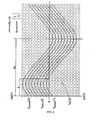
- Figures 2 and 3 may be visualized as shown in Figure 4 where the cylinder of the wellbore is unwrapped and the data is presented in two dimensions.
- the sine curves in Figure 4 are the intersecting planes where the horizontal axis is the angular displacement of the well bore oriented with the earth's axis ("north-south") or high-side of the well bore depending on well bore orientation and the vertical axis is depth along the well bore.
- the interpolation can be done at regular intervals using two or more adjacent data points as described earlier.
- Figure 4 further depicts how the dimensions of the sine curve can be used to determine the orientation of the planes' azimuth angle ⁇ a and dip angle ⁇ d.
- the azimuth angle ⁇ a is oriented to the lowest apex of the sine curve and the dip angle ⁇ d is determined from the amplitude of the sine curve as follows.
- the anisotropy may be determined at step 108 as follows.
- the average resistivity for all the interpolated values of Re intersecting the planes which is the plane resistivity R plane (m) is calculated as follows, where m is the number of data points intersecting the planes.
- the anisotropy coefficient of any rock property is defined as being between 0 and 1 which is either the vertical property divided by the horizontal property or the horizontal property divided by the vertical property.
- the anisotropy coefficient of a rock property may be defined as the numerical average divided by the harmonic average of the rock property.
- the value of the anisotropy as well as the value of the azimuth angle ⁇ a and the dip angle ⁇ d corresponding to the calculated anisotropy for the particular depth point may be stored.
- the plane is repositioned with respect to dip and/or azimuth and the anisotropy is determined and compared to the previous anisotropy measurement.
- the azimuth angle ⁇ a may be varied between 0° and 360° and/or dip angle ⁇ d may be varied between 0° and 90°. The process is repeated until a minimum anisotropy coefficient is determined at each position along the well bore or a selected interval within the well bore.
- step 110 it is determined if the anisotropy at the selected depth point has been calculated for the different values of the azimuth angle ⁇ a between 0° and 360° and/or dip angle ⁇ d between 0° and 90°. If not, at step 112 the arbitrary plane is repositioned at the selected depth point by varying the azimuth angle ⁇ a between 0° and 360° and/or dip angle ⁇ d between 0° and 90°. The anisotropy for the new orientation of the arbitrary plane is determined at step 108.
- Steps 108, 110, and 112 are repeated until the anisotropy is determined for the different values of the azimuth angle ⁇ a between 0° and 360° and/or dip angle ⁇ d between 0° and 90°. As shown in Figure 1 , the process then proceeds to step 114 where the minimum anisotropy coefficient for the particular depth point is selected. In one embodiment, all the anisotropy values stored at step 108 may be compared to determine the minimum anisotropy coefficient at the particular depth point. Once the minimum anisotropy coefficient at the particular depth point is identified, the orientation of the arbitrary plane corresponding to that minimum anisotropy coefficient value may also be identified based on the corresponding azimuth angle ⁇ a and dip angle ⁇ d.
- the minimum anisotropy coefficient and its corresponding azimuth angle ⁇ a and dip angle ⁇ d for the particular depth point may then be provided as an output.
- This minimum value of anisotropy along with the dip and azimuth of the plane now defines the anisotropy tensor for this depth point.
- the process will terminate at step 118. If the selected depth point is not the last depth point that is to be considered, the process will proceed to step 120.
- the selected depth point may then be incremented at step 120 and the process may be repeated for the entire array of measurements along the borehole or a selected portion thereof. In one embodiment, the process may only be repeated for a certain portion of the array of measurements as desired. In one exemplary embodiment, the depth may be incremented by 1 to 5 feet at step 120.
- the resulting anisotropy, dip and azimuth may be plotted with their respective depth positions to provide geological information for the particular formation.
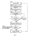
- the azimuth angle ⁇ a may be determined first followed by the dip angle ⁇ d. Accordingly, at step 402, a depth point along the well bore is selected. Next, at step 404, a set of data points that is centered around the selected depth point is identified from the array of measurements. In one embodiment, the set of data points selected for a depth point may be the set of data points that are 1-5 ft. away from the depth point. At step 406, an arbitrary plane oriented with respect to the borehole at the particular depth point is selected.
- Figure 6 depicts a series of lines where each plane is offset by a regular spacing parallel to the assumed azimuth angle ⁇ a.
- a cross section of the well bore may contain an array of circular data points 502.
- the data points do not have to be on the cross section and can be interpolated from adjacent points.
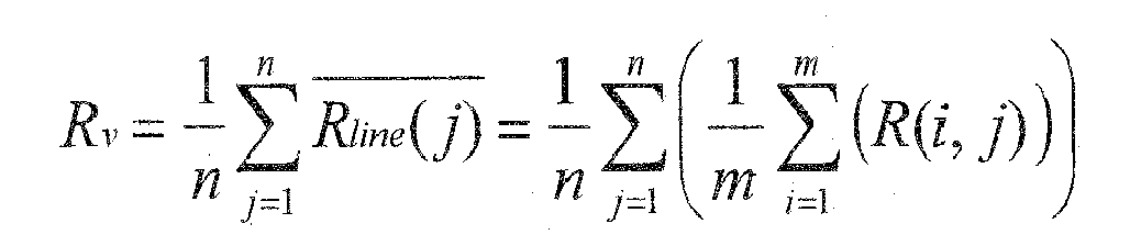
- the anisotropy may then be determined by taking the simple numerical average of all of the points for Rv and then the harmonic average for the averages of each line containing the interpolated points.
- the value of the anisotropy as well as the value of the azimuth angle ⁇ a corresponding to the calculated anisotropy for the particular depth point may be stored.
- the plane is repositioned with respect to azimuth and the anisotropy is determined and compared to the previous anisotropy measurement.
- the dip angle ⁇ d remains unchanged at this step.
- the azimuth angle ⁇ a may be varied between 0° and 360° The process is repeated until a minimum anisotropy coefficient is determined at each position along the well bore or a selected interval within the well bore.
- step 410 it is determined if the anisotropy at the selected depth point has been calculated for the different values of the azimuth angle ⁇ a between 0° and 360°, while dip angle ⁇ d remains substantially constant. If not, at step 412 the arbitrary plane is repositioned at the selected depth point by varying the azimuth angle ⁇ a between 0° and 360°. The anisotropy for the new orientation of the arbitrary plane is determined at step 408. Steps 408, 410, and 412 are repeated until the anisotropy is determined for the different values of the azimuth angle ⁇ a between 0° and 360°.
- step 414 the minimum anisotropy coefficient for the particular depth point is selected.
- all the anisotropy values stored at step 408 may be compared to determine the minimum anisotropy coefficient at the particular depth point.
- the orientation of the arbitrary plane corresponding to that minimum anisotropy coefficient value may also be identified based on the corresponding azimuth angle ⁇ a.
- the minimum anisotropy coefficient and its corresponding azimuth angle ⁇ a for the particular depth point may then be provided as an output at step 414.
- step 416 it is determined if the selected depth point is the last depth point that is to be considered in the borehole. If so, the azimuth angle ⁇ a of the plane at each depth point corresponding to the minimum anisotropy coefficient may be used at step 418 to determine an average azimuth angle ⁇ a-avg. for the particular well bore interval.
- the process will proceed to step 420.
- the selected depth point may then be incremented at step 420 and the process may be repeated for the entire array of measurements along the borehole or a selected portion thereof. In one embodiment, the process may only be repeated for a certain portion of the array of measurements as desired. In one exemplary embodiment, the depth may be incremented by 1 to 5 feet at step 420.
- the ⁇ a-avg. may be used as the assumed azimuth angle for the particular interval and used to determine the dip for this interval.
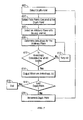
- a depth point along the well bore is selected.
- a set of data points that is centered around the selected depth point is identified from the array of measurements.
- the set of data points selected for a depth point may be the set of data points that are 1-5 ft. away from the depth point.
- an arbitrary plane oriented with respect to the borehole at the particular depth point is selected having the average azimuth angle ⁇ a-avg. and a dip angle ⁇ d.
- the up-scaled resistivity anisotropy may then be determined at step 608.
- the value of the anisotropy as well as the value of the dip angle ⁇ d corresponding to the calculated anisotropy for the particular depth point may be stored.
- the plane is repositioned with respect to dip and the anisotropy is determined and compared to the previous anisotropy measurement.
- the dip angle ⁇ d may be varied between 0° and 90°. The process is repeated until a minimum anisotropy coefficient is determined at each position along the well bore or a selected interval within the well bore.
- step 610 it is determined if the anisotropy at the selected depth point has been calculated for the different values of the dip angle ⁇ d between 0° and 90°.
- the value of the azimuth angle remains substantially constant as ⁇ a-avg..
- step 612 the arbitrary plane is repositioned at the selected depth point by varying the dip angle ⁇ d between 0° and 90°.
- the anisotropy for the new orientation of the arbitrary plane is determined at step 608. Steps 608, 610, and 612 are repeated until the anisotropy is determined for the different values of the dip angle ⁇ d between 0° and 90°.
- step 614 the minimum anisotropy coefficient for the particular depth point is selected.
- all the anisotropy values stored at step 608 may be compared to determine the minimum anisotropy coefficient at the particular depth point.
- the orientation of the arbitrary plane corresponding to that minimum anisotropy coefficient value may also be identified based on the corresponding dip angle ⁇ d.
- the minimum anisotropy coefficient and its corresponding dip angle ⁇ d for the particular depth point may then be provided as an output.
- step 616 it is determined if the selected depth point is the last depth point that is to be considered in the borehole. If so, the process terminates at step 618.
- the process will proceed to step 620.
- the selected depth point may then be incremented at step 620 and the process may be repeated for the entire array of measurements along the borehole or a selected portion thereof. In one embodiment, the process may only be repeated for a certain portion of the array of measurements as desired. In one exemplary embodiment, the depth may be incremented by 1 to 5 feet at step 620.
- determining an average azimuth angle ⁇ a-avg. may speed up the dip determination as only dip angle is determined at each step of the process of Figure 7 .
- the present invention is discussed in conjunction with resistivity images, the method may also be applied to density, porosity and acoustic image logs. Moreover, as would be appreciated by those of ordinary skill in the art, with the benefit of this disclosure, the present invention is not limited to any particular depth location within the well bore a selected interval therein. For instance, the depth locations used in conjunction with the steps of Figure 5 may be the same as or different from the depth locations used in conjunction with the steps of Figure 7 .
- the methods disclosed herein may be automated. Specifically, in one embodiment, the methods disclosed herein may be accomplished using an information handling system.
- An information handling system generally processes, compiles, stores, and/or communicates information or data for business, personal, or other purposes thereby allowing users to take advantage of the value of the information. Because technology and information handling needs and requirements vary between different users or applications, information handling systems may vary with respect to the type of information handled; the methods for handling the information; the methods for processing, storing or communicating the information; the amount of information processed, stored, or communicated; and the speed and efficiency with which the information is processed, stored, or communicated.
- information handling systems allow for information handling systems to be general or configured for a specific user or specific use such as financial transaction processing, airline reservations, enterprise data storage, or global communications.
- information handling systems may include or comprise a variety of hardware and software components that may be configured to process, store, and communicate information and may include one or more computer systems, data storage systems, and networking systems.
- the information handling system may be a desktop or a laptop computer.
- the information handling system may be communicative coupled to a logging tool. As would be appreciated by those of ordinary skill in the art, with the benefit of this disclosure, the information handling system may be coupled to the logging tool through a wired or wireless communication network. The information handling system may then receive the measurement data along the well and process that data in accordance with the methods disclosed herein to provide anisotropy, depth and azimuth information in accordance with an embodiment of the present invention.
Landscapes
- Life Sciences & Earth Sciences (AREA)
- Physics & Mathematics (AREA)
- Engineering & Computer Science (AREA)
- Environmental & Geological Engineering (AREA)
- Geology (AREA)
- High Energy & Nuclear Physics (AREA)
- General Life Sciences & Earth Sciences (AREA)
- General Physics & Mathematics (AREA)
- Geophysics (AREA)
- Geochemistry & Mineralogy (AREA)
- Remote Sensing (AREA)
- Health & Medical Sciences (AREA)
- Chemical & Material Sciences (AREA)
- Analytical Chemistry (AREA)
- Biochemistry (AREA)
- General Health & Medical Sciences (AREA)
- Immunology (AREA)
- Pathology (AREA)
- Geophysics And Detection Of Objects (AREA)
Abstract
A method of determining anisotropy in a borehole is disclosed. An array of measurements along the borehole is obtained and a first depth in the borehole is selected. An arbitrary plane oriented with respect to the borehole at the first depth is designated and an anisotropy for the first depth with respect to the arbitrary plane is determined. The arbitrary plane is repositioned at the first depth and an anisotropy for different positions of the arbitrary plane at the first depth is determined. A minimum anisotropy coefficient with respect to the arbitrary plane at the first depth is identified based on anisotropy for different positions of the arbitrary plane. An anisotropy tensor for the first depth is then identified.
Description
- The present invention relates to methods of determining anisotropy, specifically in a borehole.
- More generally, the present invention relates to oilfield operations, and more particularly, to methods and systems for determining anisotropy, dip, and azimuth from image data.
- When performing oilfield operations it is important to understand the structure and properties of the formation surrounding the well. The geological properties of the formation are important throughout the development of a well. For example, the geological properties of the formation can be used to determine if the formation contains hydrocarbons, determine the producibility of the hydrocarbons in the formation, and optimize production from the well.
- Wireline logging and/or logging-while-drilling (LWD) or measurement-while-drilling (MWD) (collectively "logs") are commonly used to obtain measurements that shed light on the geological properties of a formation. Accordingly, one or more logging tools may be lowered into the borehole and used to obtain measurements as the tools traverse the borehole. These measurements may then be used to estimate a number of desired formation properties.
- One popular logging method utilizes nuclear magnetic resonance ("NMR") measurements. The NMR measurements are based on the fact that when an assembly of magnetic moments, such as those of hydrogen nuclei, are exposed to a static magnetic field, they tend to align along the direction of the magnetic field, resulting in bulk magnetization. Accordingly, the magnetic properties of the nuclei may be used to obtain information about formation properties. Because of its non-destructive character, NMR logging has become one of the common methods for formation evaluation. NMR logging devices may be used independent of the drilling apparatus (i.e. in wireline logging) or in conjunction with the drilling apparatus (i.e. LWD/MWD) to obtain measurements while drilling is taking place.
- One of the applications of NMR and other logging techniques is the analysis of certain properties of the geological formation. Such properties may include, for example, permeability, porosity, resistivity, diffusivity, or viscosity. Anisotropic analysis of properties is particularly useful in reservoir engineering where data or logs obtained through multiple measurements at different locations may be combined in order to characterize each flow interval of the geological area by a single anisotropy, such as permeability anisotropy. The process of combining the data obtained through multiple measurements and multiple locations is referred to as "up-scaling". Because the measurement data are typically taken at various scales and use different sample sizes, up-scaling the data can be difficult.
- Typically, the measurement data is processed by visual inspection and/or correlation. For instance, a single anisotropy, such as permeability anisotropy obtained for a flow interval, may be used to predict the producibility of the well. It is often necessary to perform well testing before such performance predictions can be made. However, the performance of well testing has become undesirable due to the high economic and environmental costs associated with it.
- Additionally it is desirable to obtain dip information for a geological formation. The sedimentary portion of the earth's surface is made up of successive layers or beds which do not typically have a constant thickness. These layers often exhibit a certain dip, e.g., an inclination with respect to a horizontal plane. The dip angle is the angle between the vertical direction and a line perpendicular to the bedding plane. The relative borehole dip is the angle between the borehole and a line perpendicular to the bedding planes. The dip of formation layers in a formation penetrated by a borehole may convey important information in petroleum prospecting. For example, such information may be useful for evaluating the chances of obtaining hydrocarbons from a borehole, for establishing the nature of adjacent geological structures and for choosing the location of new boreholes.
- Accordingly, it is desirable to develop an up-scaling method which honors the petrophysical spatial relationships of the data and can be used to combine different types of data including core data, wireline logs, wireline tester data and well testing to obtain image data anisotropy and the dip angle of the anisotropy. The azimuth angle is associated with the dipping plane and is the angle formed by the plane defining the anisotropy with respect to the north axis of the earth. Relative azimuth is the angle formed by the anisotropy plane and its intersection to the borehole.
- According to a first aspect of the present invention, there is provided a method of determining anisotropy in a borehole comprising: obtaining an array of measurements along the borehole; selecting a first depth in the borehole; designating an arbitrary plane oriented with respect to the borehole at the first depth; determining an anisotropy for the first depth with respect to the arbitrary plane; repositioning the arbitrary plane at the first depth; determining an anisotropy for different positions of the arbitrary plane at the first depth; identifying a minimum anisotropy coefficient with respect to the arbitrary plane at the first depth, wherein the minimum anisotropy coefficient is identified based on the anisotropy for different positions of the arbitrary plane; and defining an anisotropy tensor for the first depth.
- According to a second aspect of the present invention, there is provided a method for determining anisotropy comprising: measuring a desired characteristic along a borehole; wherein the desired characteristic is represented by a plurality of data points along the borehole; identifying a plurality of depth locations in the borehole; selecting one of the plurality of depth locations in the borehole as a first depth location; selecting a first set of data points corresponding to the first depth location; selecting an arbitrary plane oriented with respect to the borehole at the first depth location; determining a first anisotropy for the first depth location with respect to the arbitrary plane; reorienting the arbitrary plane at the first depth location; wherein reorienting the arbitrary plane at the first depth location comprises changing at least one of an azimuth angle and a dip angle of the arbitrary plane; determining a second anisotropy for the first depth location with respect to the arbitrary plane; identifying a minimum anisotropy coefficient for the arbitrary plane at the first depth location; and outputting the minimum anisotropy coefficient of the arbitrary plane at the first depth location.
- To enable a better understanding of the present invention, and to show how the same may be carried into effect, reference will now be made, by way of example only, to the accompanying drawings, in which: -
-
Figure 1 is a flow diagram of steps of a first up-scaling method in accordance with an exemplary embodiment of the present invention; -
Figure 2 is an image array of data along a well bore axis with dipping plane intersecting the borehole in accordance with an exemplary embodiment of the present invention; -
Figure 3 depicts a series of intersecting planes each offset by a regular spacing parallel to the assumed dipping plane in accordance with an exemplary embodiment of the present invention; -
Figure 4 is a two dimensional display of the cylinder shown inFigures 2 and 3 in accordance with an exemplary embodiment of the present invention; -
Figure 5 is a flow diagram of steps of a second up-scaling method in accordance with an exemplary embodiment of the present invention; -
Figure 6 is an image array of data along a well bore axis in accordance with an exemplary embodiment of the present invention; and -
Figure 7 is a flow diagram of steps of a second up-scaling method in accordance with an exemplary embodiment of the present invention. - While explanatory embodiments of this disclosure have been depicted and described by reference to these Figures, such references do not imply a limitation on the disclosure, and no such limitation is to be inferred. The subject matter disclosed is capable of considerable modification, alteration, and equivalents in form and function, as will occur to those skilled in the pertinent art and having the benefit of this disclosure. The depicted and described embodiments of this disclosure are examples only, and not exhaustive of the scope of the disclosure.
- The present invention relates generally to oilfield operations, and more particularly, to methods and systems for determining anisotropy, dip, and azimuth from image data.
- In accordance with an embodiment of the present invention, an array of measurements is first obtained along a borehole using traditional logging tools. Using a portion of this array positioned near a depth location, an up-scaling method is used to determine the anisotropy with respect to the plane. The up-scaling methods honor the petrophysical spatial relationships of data and determine the image data anisotropy. Anisotropy is a result of thin laminations that may be virtually undetectable using normal logs but may be well within the scale of image logs. These thin laminations may be oriented to anisotropy and the bedding plane. Up scaling methods may determine the anisotropy tensor even when this may not be apparent using pattern matching and visual inspection of the data.
-
Figure 1 is a flow diagram of steps of an up-scaling method in accordance with an exemplary embodiment of the present invention. Accordingly, atstep 102, a depth point along the well bore is selected. Next, atstep 104, a set of data points that is centered around the selected depth point is identified from the array of measurements. In one embodiment, the set of data points selected for a depth point may be the set of data points that are 1-5 ft. away from the depth point. -
Figure 2 depicts an array of measurements along the borehole axis (z) with the dipping plane intersecting the borehole. As would be appreciated by those of ordinary skill in the art, with the benefit of this disclosure, the array of measurements may represent any desirable properties of the formation. In one embodiment, the array of measurement data may be an array of resistivity measurements obtained along the path of a well bore as shown inFigure 2 . In accordance with an embodiment of the present invention, the anisotropy, dip and azimuth for the formation may be determined as follows. As would be appreciated by those of ordinary skill in the art, any number of data points may be used in the following steps. Moreover, the data points need not be symmetrically distributed around the borehole axis (z) and may be randomly distributed. - Returning to
Figure 1 , atstep 106, an arbitrary plane oriented with respect to the borehole at the particular depth point is selected. The equation of thearbitrary plane 202 which passes through the origin as shown inFigure 2 , and is centered about an array of data points is as follows:
where θd is the relative dip angle with respect to the borehole axis (z) and θa is the azimuth angle with respect to the x-axis. - In some instances, the plane may not intersect the actually measured points. As would be appreciated by those of ordinary skill in the art, with the benefit of this disclosure, when the plane does not intersect the actually measured points, two or more adjacent image data points can be interpolated to determine a value which the plane intersects. In one exemplary embodiment two adjacent data points may be used and a linear interpolation may be utilized. If more than two adjacent data points are used then other interpolation methods, such as, for example, bilinear interpolation, bicubic interpolation in two dimensions, and trilinear interpolation in three dimensions may be utilized. Such methods of interpolation are well known to those of ordinary skill in the art and will therefore not be discussed in detail herein.
- Turning now to
Figure 3 , consider a series of intersectingplanes 302 that are offset from the assumed dipping plane. The number of planes and offset distance is arbitrary but should be symmetrical to the central location of all the data points considered as shown inFigure 2 . In one exemplary embodiment, the offset of theplanes 302 may be roughly equal to the point spacing and is sufficient to intersect most of the data. - In accordance with another exemplary embodiment of the present invention,
Figures 2 and 3 may be visualized as shown inFigure 4 where the cylinder of the wellbore is unwrapped and the data is presented in two dimensions. The sine curves inFigure 4 are the intersecting planes where the horizontal axis is the angular displacement of the well bore oriented with the earth's axis ("north-south") or high-side of the well bore depending on well bore orientation and the vertical axis is depth along the well bore. The interpolation can be done at regular intervals using two or more adjacent data points as described earlier.Figure 4 further depicts how the dimensions of the sine curve can be used to determine the orientation of the planes' azimuth angle θa and dip angle θd. The azimuth angle θa is oriented to the lowest apex of the sine curve and the dip angle θd is determined from the amplitude of the sine curve as follows.

- With the assumed azimuth angle θa and dip angle θd, the anisotropy may be determined at
step 108 as follows. First, the average resistivity for all the interpolated values of Re intersecting the planes which is the plane resistivity Rplane(m) is calculated as follows, where m is the number of data points intersecting the planes.
- Rplane(j) represents the average for each plane j containing m points. Further, the average Re for all n planes is the vertical resistivity and is obtained as follows:

- Next, the horizontal resistivity (Rh) is determined from harmonic average as:

- Accordingly, for an assumed azimuth angle θa and dip angle θd, the up-scaled resistivity anisotropy may be determined at
step 108 as:
- Because resistivity anisotropy is typically greater than one, it is useful to consider its inverse for imaging data. This normalizes that data from 1 to 0 and may be referred to as the resistivity anisotropy coefficient (λr) which may be determined as:

- In other forms of anisotropy such as permeability anisotropy the vertical permeability is normally lower than the horizontal permeability and therefore varies between 0 and 1. Therefore, in accordance with the methods and systems disclosed herein, the anisotropy coefficient of any rock property is defined as being between 0 and 1 which is either the vertical property divided by the horizontal property or the horizontal property divided by the vertical property. Specifically, the anisotropy coefficient of a rock property may be defined as the numerical average divided by the harmonic average of the rock property.
- As would be apparent to those of ordinary skill in the art, in one embodiment, at
step 108, the value of the anisotropy as well as the value of the azimuth angle θa and the dip angle θd corresponding to the calculated anisotropy for the particular depth point may be stored. - Returning now to
Figure 1 , once anisotropy with respect to a first arbitrary plane is determined, the plane is repositioned with respect to dip and/or azimuth and the anisotropy is determined and compared to the previous anisotropy measurement. In order to reposition the plane, the azimuth angle θa may be varied between 0° and 360° and/or dip angle θd may be varied between 0° and 90°. The process is repeated until a minimum anisotropy coefficient is determined at each position along the well bore or a selected interval within the well bore. - Specifically, as shown in
Figure 1 , atstep 110 it is determined if the anisotropy at the selected depth point has been calculated for the different values of the azimuth angle θa between 0° and 360° and/or dip angle θd between 0° and 90°. If not, atstep 112 the arbitrary plane is repositioned at the selected depth point by varying the azimuth angle θa between 0° and 360° and/or dip angle θd between 0° and 90°. The anisotropy for the new orientation of the arbitrary plane is determined atstep 108.Steps Figure 1 , the process then proceeds to step 114 where the minimum anisotropy coefficient for the particular depth point is selected. In one embodiment, all the anisotropy values stored atstep 108 may be compared to determine the minimum anisotropy coefficient at the particular depth point. Once the minimum anisotropy coefficient at the particular depth point is identified, the orientation of the arbitrary plane corresponding to that minimum anisotropy coefficient value may also be identified based on the corresponding azimuth angle θa and dip angle θd. The minimum anisotropy coefficient and its corresponding azimuth angle θa and dip angle θd for the particular depth point may then be provided as an output. This minimum value of anisotropy along with the dip and azimuth of the plane now defines the anisotropy tensor for this depth point. Atstep 116 it is determined if the selected depth point is the last depth point that is to be considered in the borehole. If so, the process will terminate atstep 118. If the selected depth point is not the last depth point that is to be considered, the process will proceed to step 120. The selected depth point may then be incremented atstep 120 and the process may be repeated for the entire array of measurements along the borehole or a selected portion thereof. In one embodiment, the process may only be repeated for a certain portion of the array of measurements as desired. In one exemplary embodiment, the depth may be incremented by 1 to 5 feet atstep 120. - Once calculations are completed for the different depth points, the resulting anisotropy, dip and azimuth may be plotted with their respective depth positions to provide geological information for the particular formation.
- Turning now to
Figure 5 , in accordance with an exemplary embodiment of the present invention, the azimuth angle θa may be determined first followed by the dip angle θd. Accordingly, atstep 402, a depth point along the well bore is selected. Next, atstep 404, a set of data points that is centered around the selected depth point is identified from the array of measurements. In one embodiment, the set of data points selected for a depth point may be the set of data points that are 1-5 ft. away from the depth point. Atstep 406, an arbitrary plane oriented with respect to the borehole at the particular depth point is selected. -
Figure 6 depicts a series of lines where each plane is offset by a regular spacing parallel to the assumed azimuth angle θa. A cross section of the well bore may contain an array of circular data points 502. As would be appreciated by those of ordinary skill in the art, with the benefit of this disclosure, the data points do not have to be on the cross section and can be interpolated from adjacent points. The anisotropy may then be determined by taking the simple numerical average of all of the points for Rv and then the harmonic average for the averages of each line containing the interpolated points. Specifically, the average for each line j, containing m points, may be obtained as:
- The average Re for all n lines may then be determined as the vertical resistivity, Rv:
- Next, the horizontal resistivity (Rv) may be determined from the harmonic average of the lines:

- Accordingly, for an assumed azimuth angle θa and dip angle θd the up-scaled resistivity anisotropy coefficient may be determined at
step 408 as:
- As would be apparent to those of ordinary skill in the art, in one embodiment, at
step 408, the value of the anisotropy as well as the value of the azimuth angle θa corresponding to the calculated anisotropy for the particular depth point may be stored. - Returning now to
Figure 5 , once anisotropy with respect to a first arbitrary plane is determined, the plane is repositioned with respect to azimuth and the anisotropy is determined and compared to the previous anisotropy measurement. The dip angle θd remains unchanged at this step. In order to reposition the plane, the azimuth angle θa may be varied between 0° and 360° The process is repeated until a minimum anisotropy coefficient is determined at each position along the well bore or a selected interval within the well bore. - Specifically, as shown in
Figure 5 , atstep 410 it is determined if the anisotropy at the selected depth point has been calculated for the different values of the azimuth angle θa between 0° and 360°, while dip angle θd remains substantially constant. If not, atstep 412 the arbitrary plane is repositioned at the selected depth point by varying the azimuth angle θa between 0° and 360°. The anisotropy for the new orientation of the arbitrary plane is determined atstep 408.Steps Figure 5 , the process then proceeds to step 414 where the minimum anisotropy coefficient for the particular depth point is selected. In one embodiment, all the anisotropy values stored atstep 408 may be compared to determine the minimum anisotropy coefficient at the particular depth point. Once the minimum anisotropy coefficient at the particular depth point is identified, the orientation of the arbitrary plane corresponding to that minimum anisotropy coefficient value may also be identified based on the corresponding azimuth angle θa. The minimum anisotropy coefficient and its corresponding azimuth angle θa for the particular depth point may then be provided as an output atstep 414. Atstep 416 it is determined if the selected depth point is the last depth point that is to be considered in the borehole. If so, the azimuth angle θa of the plane at each depth point corresponding to the minimum anisotropy coefficient may be used atstep 418 to determine an average azimuth angle θa-avg. for the particular well bore interval. - If the selected depth point is not the last depth point that is to be considered, the process will proceed to step 420. The selected depth point may then be incremented at
step 420 and the process may be repeated for the entire array of measurements along the borehole or a selected portion thereof. In one embodiment, the process may only be repeated for a certain portion of the array of measurements as desired. In one exemplary embodiment, the depth may be incremented by 1 to 5 feet atstep 420. - Once the average azimuth angle θa-av g. for the particular interval is determined, the θa-avg. may be used as the assumed azimuth angle for the particular interval and used to determine the dip for this interval. Specifically, as shown in
Figure 7 , atstep 602, a depth point along the well bore is selected. Next, atstep 604, a set of data points that is centered around the selected depth point is identified from the array of measurements. In one embodiment, the set of data points selected for a depth point may be the set of data points that are 1-5 ft. away from the depth point. Atstep 606, an arbitrary plane oriented with respect to the borehole at the particular depth point is selected having the average azimuth angle θa-avg. and a dip angle θd. As discussed above in conjunction withFigure 6 , for the assumed azimuth angle θa-avg. and dip angle θd the up-scaled resistivity anisotropy may then be determined atstep 608. - As would be apparent to those of ordinary skill in the art, in one embodiment, at
step 608, the value of the anisotropy as well as the value of the dip angle θd corresponding to the calculated anisotropy for the particular depth point may be stored. - Once anisotropy with respect to a first arbitrary plane is determined, the plane is repositioned with respect to dip and the anisotropy is determined and compared to the previous anisotropy measurement. In order to reposition the plane, the dip angle θd may be varied between 0° and 90°. The process is repeated until a minimum anisotropy coefficient is determined at each position along the well bore or a selected interval within the well bore.
- Specifically, as shown in
Figure 7 , atstep 610 it is determined if the anisotropy at the selected depth point has been calculated for the different values of the dip angle θd between 0° and 90°. The value of the azimuth angle remains substantially constant as θa-avg.. If not, atstep 612 the arbitrary plane is repositioned at the selected depth point by varying the dip angle θd between 0° and 90°. The anisotropy for the new orientation of the arbitrary plane is determined atstep 608.Steps Figure 7 , the process then proceeds to step 614 where the minimum anisotropy coefficient for the particular depth point is selected. In one embodiment, all the anisotropy values stored atstep 608 may be compared to determine the minimum anisotropy coefficient at the particular depth point. Once the minimum anisotropy coefficient at the particular depth point is identified, the orientation of the arbitrary plane corresponding to that minimum anisotropy coefficient value may also be identified based on the corresponding dip angle θd. The minimum anisotropy coefficient and its corresponding dip angle θd for the particular depth point may then be provided as an output. Atstep 616 it is determined if the selected depth point is the last depth point that is to be considered in the borehole. If so, the process terminates atstep 618. - If the selected depth point is not the last depth point that is to be considered, the process will proceed to step 620. The selected depth point may then be incremented at
step 620 and the process may be repeated for the entire array of measurements along the borehole or a selected portion thereof. In one embodiment, the process may only be repeated for a certain portion of the array of measurements as desired. In one exemplary embodiment, the depth may be incremented by 1 to 5 feet atstep 620. As would be appreciated by those of ordinary skill in the art, with the benefit of this disclosure, determining an average azimuth angle θa-avg. may speed up the dip determination as only dip angle is determined at each step of the process ofFigure 7 . - As would be appreciated by those of ordinary skill in the art, with the benefit of this disclosure, while the present invention is discussed in conjunction with resistivity images, the method may also be applied to density, porosity and acoustic image logs. Moreover, as would be appreciated by those of ordinary skill in the art, with the benefit of this disclosure, the present invention is not limited to any particular depth location within the well bore a selected interval therein. For instance, the depth locations used in conjunction with the steps of
Figure 5 may be the same as or different from the depth locations used in conjunction with the steps ofFigure 7 . - As would be appreciated by those of ordinary skill in the art, with the benefit of this disclosure, in one embodiment the methods disclosed herein may be automated. Specifically, in one embodiment, the methods disclosed herein may be accomplished using an information handling system. An information handling system generally processes, compiles, stores, and/or communicates information or data for business, personal, or other purposes thereby allowing users to take advantage of the value of the information. Because technology and information handling needs and requirements vary between different users or applications, information handling systems may vary with respect to the type of information handled; the methods for handling the information; the methods for processing, storing or communicating the information; the amount of information processed, stored, or communicated; and the speed and efficiency with which the information is processed, stored, or communicated. The variations in information handling systems allow for information handling systems to be general or configured for a specific user or specific use such as financial transaction processing, airline reservations, enterprise data storage, or global communications. In addition, information handling systems may include or comprise a variety of hardware and software components that may be configured to process, store, and communicate information and may include one or more computer systems, data storage systems, and networking systems. In one embodiment, the information handling system may be a desktop or a laptop computer.
- The information handling system may be communicative coupled to a logging tool. As would be appreciated by those of ordinary skill in the art, with the benefit of this disclosure, the information handling system may be coupled to the logging tool through a wired or wireless communication network. The information handling system may then receive the measurement data along the well and process that data in accordance with the methods disclosed herein to provide anisotropy, depth and azimuth information in accordance with an embodiment of the present invention.
- Therefore, the present invention is well-adapted to carry out the objects and attain the ends and advantages mentioned as well as those which are inherent therein. While the invention has been depicted and described by reference to exemplary embodiments of the invention, such a reference does not imply a limitation on the invention, and no such limitation is to be inferred. The invention is capable of considerable modification, alteration, and equivalents in form and function, as will occur to those ordinarily skilled in the pertinent arts and having the benefit of this disclosure. The depicted and described embodiments of the invention are exemplary only, and are not exhaustive of the scope of the invention. Consequently, the invention is intended to be limited only by the spirit and scope of the appended claims, giving full cognizance to equivalents in all respects. The terms in the claims have their plain, ordinary meaning unless otherwise explicitly and clearly defined by the patentee.
Claims (20)
- A method of determining anisotropy in a borehole comprising:obtaining an array of measurements along the borehole;selecting a first depth in the borehole;designating an arbitrary plane oriented with respect to the borehole at the first depth;determining an anisotropy for the first depth with respect to the arbitrary plane;repositioning the arbitrary plane at the first depth;determining an anisotropy for different positions of the arbitrary plane at the first depth;identifying a minimum anisotropy coefficient with respect to the arbitrary plane at the first depth,
wherein the minimum anisotropy coefficient is identified based on the anisotropy for different positions of the arbitrary plane; anddefining an anisotropy tensor for the first depth. - The method of claim 1, wherein the arbitrary plane is repositioned by varying at least one of an azimuth angle and a dip angle.
- The method of claim 2, wherein at least one of the azimuth angle is varied between 0° and 360° and the dip angle is varied between 0° and 90°
- The method of any preceding claim, wherein determining an anisotropy for the first depth with respect to the arbitrary plane comprises:determining a horizontal resistivity for the arbitrary plane;determining a vertical resistivity for the arbitrary plane; anddetermining anisotropy for the arbitrary plane using the horizontal resistivity of the arbitrary plane and the vertical resistivity of the arbitrary plane.
- The method of claim 4, wherein determining the horizontal resistivity of the arbitrary plane comprises:designating two or more intersecting planes, wherein the intersecting planes are offset from the arbitrary plane;calculating a horizontal resistivity for each of the two or more intersecting planes;
anddetermining the horizontal resistivity for the arbitrary plane as an average of the horizontal resistivity for each of the two or more intersecting planes. - The method of any preceding claim, wherein the array of measurements is selected from a group consisting of a resistivity measurement, a density measurement, an acoustic measurement, and a porosity measurement.
- The method of any preceding claim, wherein the anisotropy tensor for the first depth comprises at least one of the minimum anisotropy coefficient for the first depth; an azimuth angle of the arbitrary plane corresponding to the minimum anisotropy coefficient for the first depth; and a dip angle of the arbitrary plane corresponding to the minimum anisotropy coefficient for the first depth.
- A method for determining anisotropy comprising:measuring a desired characteristic along a borehole;
wherein the desired characteristic is represented by a plurality of data points along the borehole;identifying a plurality of depth locations in the borehole;selecting one of the plurality of depth locations in the borehole as a first depth location;selecting a first set of data points corresponding to the first depth location;selecting an arbitrary plane oriented with respect to the borehole at the first depth location;determining a first anisotropy for the first depth location with respect to the arbitrary plane;reorienting the arbitrary plane at the first depth location;
wherein reorienting the arbitrary plane at the first depth location comprises changing at least one of an azimuth angle and a dip angle of the arbitrary plane;determining a second anisotropy for the first depth location with respect to the arbitrary plane;identifying a minimum anisotropy coefficient for the arbitrary plane at the first depth location; andoutputting the minimum anisotropy coefficient of the arbitrary plane at the first depth location. - The method of claim 8, wherein the depth locations are at a predetermined distance from each other.
- The method of claim 8 or 9, further comprising outputting the dip angle and the azimuth angle of the arbitrary plane corresponding to the minimum anisotropy coefficient.
- The method of claim 8, 9 or 10 wherein changing at least one of the azimuth angle and the dip angle of the arbitrary plane comprises at least one of changing the azimuth angle between 0° and 360° and changing the dip angle between 0° and 90°
- The method of claim 8 9, 10 or 11, wherein the desired characteristic is selected from a group consisting of a resistivity characteristic, a porosity characteristic, an acoustic characteristic, and a density characteristic.
- The method of any one of claims 8 to 12, wherein determining a first anisotropy for the first depth location with respect to the arbitrary plane comprises:determining a horizontal resistivity for the arbitrary plane;determining a vertical resistivity for the arbitrary plane; anddetermining anisotropy for the arbitrary plane using the horizontal resistivity of the arbitrary plane and the vertical resistivity of the arbitrary plane.
- The method of any one of claims 8 to 13 further comprising:selecting one of the plurality of depth locations in the borehole as a second depth location;
wherein the second depth location is different from the first depth location;selecting a second set of data points corresponding to the second depth location;selecting an arbitrary plane oriented with respect to the borehole at the second depth location;determining a first anisotropy for the second depth location with respect to the arbitrary plane;reorienting the arbitrary plane at the second depth location;
wherein reorienting the arbitrary plane at the second depth location comprises changing at least one of an azimuth angle and a dip angle of the arbitrary plane;determining a second anisotropy for the second depth location with respect to the arbitrary plane;identifying a minimum anisotropy coefficient for the arbitrary plane at the second depth location; andoutputting the minimum anisotropy coefficient of the arbitrary plane at the second depth location. - The method of any one of claims 1 to 7, wherein:obtaining an array of measurements along the borehole comprises obtaining an array of measurements along a selected interval in the borehole;the method further comprises determining an average azimuth angle for the selected interval in the borehole;
the first depth is in the selected interval in the borehole;the arbitrary plane is oriented at the average azimuth angle and a dip angle;repositioning the arbitrary plane at the first depth comprises changing the dip angle of the arbitrary plane; andthe minimum anisotropy coefficient is identified based on the anisotropy for different positions of the arbitrary plane at the first depth. - The method of claim 15, further comprising:selecting a second depth in the borehole;
designating an arbitrary plane oriented with respect to the borehole at the second depth in the selected interval in the borehole;
wherein the arbitrary plane is oriented at the average azimuth angle;determining an anisotropy for the second depth with respect to the arbitrary plane;repositioning the arbitrary plane at the second depth;wherein repositioning the arbitrary plane at the second depth comprises changing the dip angle of the arbitrary plane;determining an anisotropy for different positions of the arbitrary plane;identifying a minimum anisotropy coefficient with respect to the arbitrary plane at the second depth;
wherein the minimum anisotropy coefficient is identified based on the anisotropy for the different positions of the arbitrary plane; anddefining an anisotropy tensor for the second depth. - The method of claim 15 or 16, wherein determining an average azimuth angle for the selected interval in the borehole comprises:obtaining an array of measurements along the selected interval in the borehole;selecting a third depth in the borehole;designating an arbitrary plane oriented with respect to the borehole at the third depth;determining an anisotropy for the third depth with respect to the arbitrary plane;repositioning the arbitrary plane at the third depth;
wherein repositioning the arbitrary plane at the third depth comprises changing an azimuth angle of the arbitrary plane;determining an anisotropy for different positions of the arbitrary plane at the third depth;identifying a minimum anisotropy coefficient with respect to the arbitrary plane at the third depth;
wherein the minimum anisotropy coefficient is identified based on the anisotropy for the different positions of the arbitrary plane at the third depth;identifying a first azimuth angle corresponding to the minimum anisotropy coefficient with respect to the arbitrary plane at the third depth;selecting a fourth depth in the borehole;designating an arbitrary plane oriented with respect to the borehole at the fourth depth;determining an anisotropy for the fourth depth with respect to the arbitrary plane;repositioning the arbitrary plane at the fourth depth;
wherein repositioning the arbitrary plane at the fourth depth comprises changing the azimuth angle of the arbitrary plane;determining an anisotropy for different positions of the arbitrary plane at the fourth depth;identifying a minimum anisotropy coefficient with respect to the arbitrary plane at the fourth depth;identifying a second azimuth angle corresponding to the minimum anisotropy coefficient with respect to the arbitrary plane at the fourth depth;determining an average azimuth angle for the selected interval in the borehole using the first azimuth angle and the second azimuth angle. - The method of claim 15, 16 or 17 further comprising outputting a dip angle and an azimuth angle of the arbitrary plane corresponding to the minimum anisotropy coefficient at the first depth.
- The method of claim 15, 16, 17 or 18 wherein changing the dip angle of the arbitrary plane comprises changing the dip angle between 0° and 90°.
- The method of any one of claims 15 to 19, wherein the array of measurements represent a desired characteristic selected from a group consisting of resistivity characteristic, porosity characteristic, acoustic characteristic, and density characteristic.
Applications Claiming Priority (1)
| Application Number | Priority Date | Filing Date | Title |
|---|---|---|---|
| US13/110,404 US8614577B2 (en) | 2011-05-18 | 2011-05-18 | Automatic anisotropy, azimuth and dip determination from upscaled image log data |
Publications (1)
| Publication Number | Publication Date |
|---|---|
| EP2527876A1 true EP2527876A1 (en) | 2012-11-28 |
Family
ID=46168159
Family Applications (1)
| Application Number | Title | Priority Date | Filing Date |
|---|---|---|---|
| EP12168527A Withdrawn EP2527876A1 (en) | 2011-05-18 | 2012-05-18 | Automatic anisotropy, azimuth and dip determination from upscaled image log data |
Country Status (2)
| Country | Link |
|---|---|
| US (1) | US8614577B2 (en) |
| EP (1) | EP2527876A1 (en) |
Families Citing this family (6)
| Publication number | Priority date | Publication date | Assignee | Title |
|---|---|---|---|---|
| US9659252B2 (en) * | 2012-01-23 | 2017-05-23 | Schlumberger Technology Corporation | Method to characterize heterogeneous anisotropic media |
| RU2606249C1 (en) * | 2013-01-17 | 2017-01-10 | Халлибертон Энерджи Сервисез, Инк. | System and method for formation angle of incidence quick assessment |
| WO2015053876A1 (en) | 2013-10-08 | 2015-04-16 | Exxonmobil Upstream Research Company | Automatic dip picking from wellbore azimuthal image logs |
| US11231517B2 (en) * | 2018-02-27 | 2022-01-25 | Sanvean Technologies Llc | Azimuthal measurement for geosteering |
| CN111796333B (en) * | 2020-06-29 | 2023-09-26 | 中国石油天然气集团有限公司 | Electrical equalization method of microresistivity imaging data based on sliding window |
| US20250043677A1 (en) * | 2023-07-31 | 2025-02-06 | Halliburton Energy Services, Inc. | Automatic Dip Picking From Azimuthal Borehole Images |
Family Cites Families (20)
| Publication number | Priority date | Publication date | Assignee | Title |
|---|---|---|---|---|
| US5960371A (en) * | 1997-09-04 | 1999-09-28 | Schlumberger Technology Corporation | Method of determining dips and azimuths of fractures from borehole images |
| US6727706B2 (en) * | 2001-08-09 | 2004-04-27 | Halliburton Energy Services, Inc. | Virtual steering of induction tool for determination of formation dip angle |
| CA2468865A1 (en) * | 2001-12-03 | 2003-06-12 | Shell Internationale Research Maatschappij B.V. | Method for determining anisotropic resistivity and dip angle in an earth formation |
| US7463035B2 (en) * | 2002-03-04 | 2008-12-09 | Baker Hughes Incorporated | Method and apparatus for the use of multicomponent induction tool for geosteering and formation resistivity data interpretation in horizontal wells |
| US6922373B2 (en) * | 2002-09-14 | 2005-07-26 | Schlumberger Technology Corporation | Method of estimating relative bearing of a borehole receiver |
| AU2003278893A1 (en) * | 2002-09-27 | 2004-04-19 | Baker Hughes Incorporated | A method for resistivity anisotropy determination in conductive borehole environments |
| US6819111B2 (en) * | 2002-11-22 | 2004-11-16 | Baker Hughes Incorporated | Method of determining vertical and horizontal resistivity, and relative dip in anisotropic earth formations having an arbitrary electro-magnetic antenna combination and orientation with additional rotation and position measurements |
| US7224162B2 (en) * | 2003-10-04 | 2007-05-29 | Halliburton Energy Services Group, Inc. | System and methods for upscaling petrophysical data |
| US7027926B2 (en) * | 2004-04-19 | 2006-04-11 | Pathfinder Energy Services, Inc. | Enhanced measurement of azimuthal dependence of subterranean parameters |
| GB2429484B (en) * | 2004-05-21 | 2009-10-28 | Halliburton Energy Serv Inc | Methods and apparatus for measuring formation properties |
| EP1783517A1 (en) * | 2005-11-04 | 2007-05-09 | AGELLIS Group AB | Multi-dimensional imaging method and apparatus |
| CA2650598A1 (en) * | 2006-04-26 | 2007-11-08 | Baker Hughes Incorporated | Method and apparatus for correcting underestimation of formation anisotropy ratio |
| US7778778B2 (en) * | 2006-08-01 | 2010-08-17 | Baker Hughes Incorporated | Correction of multi-component measurements for tool eccentricity in deviated wells |
| US8121788B2 (en) * | 2007-12-21 | 2012-02-21 | Schlumberger Technology Corporation | Method and system to automatically correct LWD depth measurements |
| US8073623B2 (en) * | 2008-01-04 | 2011-12-06 | Baker Hughes Incorporated | System and method for real-time quality control for downhole logging devices |
| US8060309B2 (en) * | 2008-01-29 | 2011-11-15 | Baker Hughes Incorporated | Characterization of fracture length and formation resistivity from array induction data |
| US8680865B2 (en) * | 2010-03-19 | 2014-03-25 | Schlumberger Technology Corporation | Single well reservoir imaging apparatus and methods |
| CA2781567C (en) * | 2010-04-07 | 2015-06-16 | Precision Energy Services, Inc. | Multi-well interference testing and in-situ reservoir behavior characterization |
| US20120242342A1 (en) * | 2011-03-21 | 2012-09-27 | Baker Hughes Incorporated | Correction of Deep Azimuthal Resistivity Measurements for Bending |
| US8954280B2 (en) * | 2011-05-05 | 2015-02-10 | Halliburton Energy Services, Inc. | Methods and systems for determining formation parameters using a rotating tool equipped with tilted antenna loops |
-
2011
- 2011-05-18 US US13/110,404 patent/US8614577B2/en active Active
-
2012
- 2012-05-18 EP EP12168527A patent/EP2527876A1/en not_active Withdrawn
Non-Patent Citations (2)
| Title |
|---|
| TEGWYN PERKINS, MARK PROETT AND RON STAMM: "Another Dimension to Imaging: New Image Process Technique Reveals Hidden Formation Structures", 17 March 2011 (2011-03-17), XP002684248, Retrieved from the Internet <URL:http://www.spwla-abudhabi.com/pdf/Day2_5-SPWLA-Perkins-AnotherDimensiontoImagingv2.pdf> [retrieved on 20110317] * |
| TEGWYN PERKINS, MARK PROETT, RON STAMM: "NEW IMAGE PROCESS TECHNIQUE REVEALS NEW HIDDEN FORMATION STRUCTURES USING ANISOTROPY AND DIP IMAGES", 17 March 2011 (2011-03-17), pages 1 - 8, XP002684249, Retrieved from the Internet <URL:http://www.spwla.org/publications/view/item/3739> [retrieved on 20110317] * |
Also Published As
| Publication number | Publication date |
|---|---|
| US20120293178A1 (en) | 2012-11-22 |
| US8614577B2 (en) | 2013-12-24 |
Similar Documents
| Publication | Publication Date | Title |
|---|---|---|
| US9606257B2 (en) | Real-time fracture detection and fracture orientation estimation using tri-axial induction measurements | |
| AU2012387170B2 (en) | Methods and systems for borehole image forward modeling of formation properties | |
| Yenugu et al. | Seismic texture analysis for reservoir prediction and characterization | |
| US8614577B2 (en) | Automatic anisotropy, azimuth and dip determination from upscaled image log data | |
| US10732310B2 (en) | Seismic attributes derived from the relative geological age property of a volume-based model | |
| Kosari et al. | Fracture characterization by fusion of geophysical and geomechanical data: a case study from the Asmari reservoir, the Central Zagros fold-thrust belt | |
| Dong et al. | A method to construct high-precision complex pore digital rock | |
| Ding et al. | Reliability analysis of seismic attribute in the detection of fault-karst | |
| Mehdipour et al. | The best scenario for geostatistical modeling of porosity in the Sarvak reservoir in an Iranian oil field, using electrofacies, seismic facies, and seismic attributes | |
| Gao et al. | Seismic structure and texture analyses for fractured reservoir characterization: An integrated workflow | |
| He et al. | Radial resistivity measurement method for cylindrical core samples | |
| Al-Ameri et al. | Investigating geomechanical considerations on suitable layer selection for hydraulically fractured horizontal wells placement in tight reservoirs | |
| Frykman et al. | Geostatistical scaling laws applied to core and log data | |
| US20150316682A1 (en) | Distributing petrofacies using analytical modeling | |
| Aadnoy | Quality assurance of wellbore stability analyses | |
| Wu et al. | Detection performance and grading-selection-based inversion of low-frequency alternating current resistivity logging in moderate-high resistance formations | |
| Omeragic et al. | Triaxial induction interpretation in horizontal wells: Mapping boundaries, and characterizing anisotropy and fractures | |
| Calleja et al. | Multi-sensor geosteering | |
| Passey et al. | A systematic approach to evaluate hydrocarbons in thinly bedded reservoirs | |
| Pickup et al. | Geology, geometry, and effective flow | |
| Zhao et al. | Application of apparent resistivity ratio on the interpretation of small central-loop TEM survey in areas of conductive overburden | |
| CN118091786B (en) | Fracture line density correction method and device based on downhole logging data | |
| Ismagilov et al. | Machine learning approach to open hole interpretation and static modelling applied to a giant field | |
| Hati et al. | Identifying Producing Horizons in Fractured Reservoirs a Far Field Acoustic Approach | |
| Camara Salim et al. | Novel 3D Reservoir Characterization Approach in High-Angle Wells by Means of Multiphysics Integration of Seismic and Advanced LWD Ultra-Deep Resistivity Inversions |
Legal Events
| Date | Code | Title | Description |
|---|---|---|---|
| PUAI | Public reference made under article 153(3) epc to a published international application that has entered the european phase |
Free format text: ORIGINAL CODE: 0009012 |
|
| AK | Designated contracting states |
Kind code of ref document: A1 Designated state(s): AL AT BE BG CH CY CZ DE DK EE ES FI FR GB GR HR HU IE IS IT LI LT LU LV MC MK MT NL NO PL PT RO RS SE SI SK SM TR |
|
| AX | Request for extension of the european patent |
Extension state: BA ME |
|
| STAA | Information on the status of an ep patent application or granted ep patent |
Free format text: STATUS: THE APPLICATION IS DEEMED TO BE WITHDRAWN |
|
| 18D | Application deemed to be withdrawn |
Effective date: 20130529 |