EP2527823A1 - Excretion detector and absorbent article - Google Patents
Excretion detector and absorbent article Download PDFInfo
- Publication number
- EP2527823A1 EP2527823A1 EP11734675A EP11734675A EP2527823A1 EP 2527823 A1 EP2527823 A1 EP 2527823A1 EP 11734675 A EP11734675 A EP 11734675A EP 11734675 A EP11734675 A EP 11734675A EP 2527823 A1 EP2527823 A1 EP 2527823A1
- Authority
- EP
- European Patent Office
- Prior art keywords
- neutralizer
- excretion
- detection device
- retention unit
- bodily waste
- Prior art date
- Legal status (The legal status is an assumption and is not a legal conclusion. Google has not performed a legal analysis and makes no representation as to the accuracy of the status listed.)
- Granted
Links
- 230000029142 excretion Effects 0.000 title claims abstract description 130
- 230000002745 absorbent Effects 0.000 title claims description 19
- 239000002250 absorbent Substances 0.000 title claims description 19
- 230000014759 maintenance of location Effects 0.000 claims abstract description 104
- 238000001514 detection method Methods 0.000 claims abstract description 81
- 239000002699 waste material Substances 0.000 claims abstract description 60
- 239000000463 material Substances 0.000 claims abstract description 15
- GPRLSGONYQIRFK-UHFFFAOYSA-N hydron Chemical compound [H+] GPRLSGONYQIRFK-UHFFFAOYSA-N 0.000 claims abstract description 6
- 239000008151 electrolyte solution Substances 0.000 claims description 78
- 239000000243 solution Substances 0.000 claims description 20
- 239000006096 absorbing agent Substances 0.000 claims description 19
- 239000007788 liquid Substances 0.000 claims description 5
- 238000007726 management method Methods 0.000 description 24
- 210000002700 urine Anatomy 0.000 description 22
- 230000005540 biological transmission Effects 0.000 description 15
- 230000013872 defecation Effects 0.000 description 13
- FAPWRFPIFSIZLT-UHFFFAOYSA-M Sodium chloride Chemical compound [Na+].[Cl-] FAPWRFPIFSIZLT-UHFFFAOYSA-M 0.000 description 12
- KRKNYBCHXYNGOX-UHFFFAOYSA-N citric acid Chemical compound OC(=O)CC(O)(C(O)=O)CC(O)=O KRKNYBCHXYNGOX-UHFFFAOYSA-N 0.000 description 12
- 230000027939 micturition Effects 0.000 description 12
- 229910052782 aluminium Inorganic materials 0.000 description 10
- XAGFODPZIPBFFR-UHFFFAOYSA-N aluminium Chemical compound [Al] XAGFODPZIPBFFR-UHFFFAOYSA-N 0.000 description 10
- 239000002585 base Substances 0.000 description 8
- 238000003825 pressing Methods 0.000 description 8
- 238000004519 manufacturing process Methods 0.000 description 6
- 239000011780 sodium chloride Substances 0.000 description 6
- 230000001413 cellular effect Effects 0.000 description 5
- 238000010586 diagram Methods 0.000 description 5
- 239000010408 film Substances 0.000 description 5
- BQCADISMDOOEFD-UHFFFAOYSA-N Silver Chemical compound [Ag] BQCADISMDOOEFD-UHFFFAOYSA-N 0.000 description 4
- 238000005260 corrosion Methods 0.000 description 4
- 230000007797 corrosion Effects 0.000 description 4
- 238000000034 method Methods 0.000 description 4
- 230000000717 retained effect Effects 0.000 description 4
- 229910052709 silver Inorganic materials 0.000 description 4
- 239000004332 silver Substances 0.000 description 4
- 238000003860 storage Methods 0.000 description 4
- 229920001169 thermoplastic Polymers 0.000 description 4
- 239000004416 thermosoftening plastic Substances 0.000 description 4
- RYGMFSIKBFXOCR-UHFFFAOYSA-N Copper Chemical compound [Cu] RYGMFSIKBFXOCR-UHFFFAOYSA-N 0.000 description 3
- 229910052802 copper Inorganic materials 0.000 description 3
- 239000010949 copper Substances 0.000 description 3
- 208000019206 urinary tract infection Diseases 0.000 description 3
- XLYOFNOQVPJJNP-UHFFFAOYSA-N water Substances O XLYOFNOQVPJJNP-UHFFFAOYSA-N 0.000 description 3
- OKTJSMMVPCPJKN-UHFFFAOYSA-N Carbon Chemical compound [C] OKTJSMMVPCPJKN-UHFFFAOYSA-N 0.000 description 2
- XEEYBQQBJWHFJM-UHFFFAOYSA-N Iron Chemical compound [Fe] XEEYBQQBJWHFJM-UHFFFAOYSA-N 0.000 description 2
- HCHKCACWOHOZIP-UHFFFAOYSA-N Zinc Chemical compound [Zn] HCHKCACWOHOZIP-UHFFFAOYSA-N 0.000 description 2
- 239000007864 aqueous solution Substances 0.000 description 2
- 229910052799 carbon Inorganic materials 0.000 description 2
- 230000007613 environmental effect Effects 0.000 description 2
- PCHJSUWPFVWCPO-UHFFFAOYSA-N gold Chemical compound [Au] PCHJSUWPFVWCPO-UHFFFAOYSA-N 0.000 description 2
- 229910052737 gold Inorganic materials 0.000 description 2
- 239000010931 gold Substances 0.000 description 2
- 229910052751 metal Inorganic materials 0.000 description 2
- 239000002184 metal Substances 0.000 description 2
- 239000000203 mixture Substances 0.000 description 2
- 229920000098 polyolefin Polymers 0.000 description 2
- 230000002035 prolonged effect Effects 0.000 description 2
- 239000002904 solvent Substances 0.000 description 2
- KDYFGRWQOYBRFD-UHFFFAOYSA-N succinic acid Chemical compound OC(=O)CCC(O)=O KDYFGRWQOYBRFD-UHFFFAOYSA-N 0.000 description 2
- 229910052725 zinc Inorganic materials 0.000 description 2
- 239000011701 zinc Substances 0.000 description 2
- 229910018626 Al(OH) Inorganic materials 0.000 description 1
- FEWJPZIEWOKRBE-JCYAYHJZSA-N Dextrotartaric acid Chemical compound OC(=O)[C@H](O)[C@@H](O)C(O)=O FEWJPZIEWOKRBE-JCYAYHJZSA-N 0.000 description 1
- 241000282414 Homo sapiens Species 0.000 description 1
- 241001465754 Metazoa Species 0.000 description 1
- FEWJPZIEWOKRBE-UHFFFAOYSA-N Tartaric acid Natural products [H+].[H+].[O-]C(=O)C(O)C(O)C([O-])=O FEWJPZIEWOKRBE-UHFFFAOYSA-N 0.000 description 1
- 239000002253 acid Substances 0.000 description 1
- 239000003513 alkali Substances 0.000 description 1
- 239000003990 capacitor Substances 0.000 description 1
- 239000000470 constituent Substances 0.000 description 1
- 230000000694 effects Effects 0.000 description 1
- 239000003792 electrolyte Substances 0.000 description 1
- 239000000835 fiber Substances 0.000 description 1
- 238000007654 immersion Methods 0.000 description 1
- 229910052742 iron Inorganic materials 0.000 description 1
- 230000002101 lytic effect Effects 0.000 description 1
- 239000001384 succinic acid Substances 0.000 description 1
- 229920003002 synthetic resin Polymers 0.000 description 1
- 239000000057 synthetic resin Substances 0.000 description 1
- 239000011975 tartaric acid Substances 0.000 description 1
- 235000002906 tartaric acid Nutrition 0.000 description 1
- 239000010409 thin film Substances 0.000 description 1
- 230000002485 urinary effect Effects 0.000 description 1
Images



Classifications
-
- A—HUMAN NECESSITIES
- A61—MEDICAL OR VETERINARY SCIENCE; HYGIENE
- A61F—FILTERS IMPLANTABLE INTO BLOOD VESSELS; PROSTHESES; DEVICES PROVIDING PATENCY TO, OR PREVENTING COLLAPSING OF, TUBULAR STRUCTURES OF THE BODY, e.g. STENTS; ORTHOPAEDIC, NURSING OR CONTRACEPTIVE DEVICES; FOMENTATION; TREATMENT OR PROTECTION OF EYES OR EARS; BANDAGES, DRESSINGS OR ABSORBENT PADS; FIRST-AID KITS
- A61F5/00—Orthopaedic methods or devices for non-surgical treatment of bones or joints; Nursing devices ; Anti-rape devices
- A61F5/44—Devices worn by the patient for reception of urine, faeces, catamenial or other discharge; Colostomy devices
- A61F5/451—Genital or anal receptacles
-
- A—HUMAN NECESSITIES
- A61—MEDICAL OR VETERINARY SCIENCE; HYGIENE
- A61F—FILTERS IMPLANTABLE INTO BLOOD VESSELS; PROSTHESES; DEVICES PROVIDING PATENCY TO, OR PREVENTING COLLAPSING OF, TUBULAR STRUCTURES OF THE BODY, e.g. STENTS; ORTHOPAEDIC, NURSING OR CONTRACEPTIVE DEVICES; FOMENTATION; TREATMENT OR PROTECTION OF EYES OR EARS; BANDAGES, DRESSINGS OR ABSORBENT PADS; FIRST-AID KITS
- A61F13/00—Bandages or dressings; Absorbent pads
- A61F13/15—Absorbent pads, e.g. sanitary towels, swabs or tampons for external or internal application to the body; Supporting or fastening means therefor; Tampon applicators
- A61F13/42—Absorbent pads, e.g. sanitary towels, swabs or tampons for external or internal application to the body; Supporting or fastening means therefor; Tampon applicators with wetness indicator or alarm
-
- A—HUMAN NECESSITIES
- A61—MEDICAL OR VETERINARY SCIENCE; HYGIENE
- A61F—FILTERS IMPLANTABLE INTO BLOOD VESSELS; PROSTHESES; DEVICES PROVIDING PATENCY TO, OR PREVENTING COLLAPSING OF, TUBULAR STRUCTURES OF THE BODY, e.g. STENTS; ORTHOPAEDIC, NURSING OR CONTRACEPTIVE DEVICES; FOMENTATION; TREATMENT OR PROTECTION OF EYES OR EARS; BANDAGES, DRESSINGS OR ABSORBENT PADS; FIRST-AID KITS
- A61F13/00—Bandages or dressings; Absorbent pads
- A61F13/15—Absorbent pads, e.g. sanitary towels, swabs or tampons for external or internal application to the body; Supporting or fastening means therefor; Tampon applicators
- A61F13/42—Absorbent pads, e.g. sanitary towels, swabs or tampons for external or internal application to the body; Supporting or fastening means therefor; Tampon applicators with wetness indicator or alarm
- A61F2013/424—Absorbent pads, e.g. sanitary towels, swabs or tampons for external or internal application to the body; Supporting or fastening means therefor; Tampon applicators with wetness indicator or alarm having an electronic device
Definitions
- the present invention relates to an excretion detection device, by which the excretion of bodily waste from a living body is detected, and an absorbent article including such an excretion detection device.
- an excretion detection device configured to detect the excretion of urine or stool from a wearer (living body) of the absorbent article.
- the excretion detection device is loaded in the absorbent article, and upon detection of the excretion of urine or stool from the wearer, the excretion detection device reports the excretion to the outside.
- the aforementioned conventional excretion detection device has the following problem. That is, although the electrodes are in contact with the bodily waste of the wearer, if the pH of the bodily waste is high, corrosion of the electrodes speeds up. Particularly, the pH of urine of elderly persons is often high due to urinary tract infections and the like, and therefore, when the electrodes come in contact with such urine having a high pH, the electrodes corrode fast, and a sufficient electrification time cannot be secured, which is a point of concern.
- an object of the present invention is to provide an excretion detection device by which a sufficient electrification time can be secured even in the case of contact with urine with a high pH, without significantly increasing the manufacturing cost, and also to provide an absorbent article having such an excretion detection device.
- the characteristic of the present invention is an excretion detection device (excretion detection device 10) configured to detect excretion of bodily waste (bodily waste Ex, e.g., urine and stool) from a living body (wearer W), comprising: a power supply unit (power supply unit 160) having electrodes (electrode 121, electrode 122) configured by using materials with different ionization tendencies; a neutralizer retention unit (neutralizer retention unit 112) configured to retain a neutralizer (neutralizer N) for reducing the hydrogen ion index of the bodily waste; and a notification unit (radio transmission unit 180) operated by the electric power generated by the power supply unit, and configured to notify the excretion from the living body to outside the excretion detection device, wherein the electrodes are provided at a position where the electrodes can be in contact with the bodily waste, and the neutralizer retention unit is provided at a position where the neutralizer can be in contact with the bodily
- the excretion detection device preferably comprises a solution retention unit (electrolyte solution retention unit 111) configured to retain an electrolyte solution (electrolyte solution WT), wherein the electrodes are provided at a position where the electrodes can be in contact with the bodily waste and the electrolyte solution, and can also be in contact with the electrolyte solution before the excretion of the bodily waste.
- a solution retention unit electrolyte solution retention unit 111
- electrolyte solution WT electrolyte solution WT
- the neutralizer retention unit is preferably provided so as to be positioned at the upper side of the electrodes during the use of the excretion detection device.
- the neutralizer retention unit is preferably adjacent to the solution retention unit.
- the neutralizer is preferably made to seep out from the neutralizer retention unit by performing a predetermined operation for the neutralizer retention unit, and the neutralizer is brought in contact with the bodily waste.
- the electrolyte solution is preferably made to seep out from the solution retention unit by performing a predetermined operation (e.g., pressing) for the solution retention unit, and the electrolyte solution is brought in contact with the electrodes.
- a predetermined operation e.g., pressing
- an absorbent article e.g., disposable diaper 10A worn by a living body and configured to absorb the bodily waste from the living body
- the absorbent article includes an excretion detection device configured to detect the excretion of the bodily waste
- the excretion detection device comprises: a power supply unit having electrodes configured by using materials with different ionization tendencies; a neutralizer retention unit configured to retain a neutralizer for reducing the hydrogen ion index of the bodily waste; and a notification unit operated by the electric power generated by the power supply unit, and configured to notify excretion from the living body to outside the excretion detection device, wherein the electrodes are provided at a position where the electrodes can be in contact with the bodily waste, and the neutralizer retention unit is provided at a position where the neutralizer can be in contact with the bodily waste.
- the absorbent article preferably comprises: a topsheet (topsheet 11) that is in contact with the living body and allows the passage of liquids; and an absorber (absorber 13) configured to absorb the bodily waste, and the excretion detection device is provided between the topsheet and the absorber.
- an excretion detection device by which a sufficient electrification time can be secured even in the case of contact with urine with a high pH, without increasing the manufacturing cost substantially, and also to provide an absorbent article having such an excretion detection device.
- Fig. 1 is a diagram showing an entire schematic configuration of an excretion management system 1 according to the present embodiment.
- the excretion management system 1 is configured by a radio relay station 20, an excretion management server 40, and an excretion detection device 100.
- a disposable diaper 10A and a disposable diaper 10B are absorbent articles worn by a wearer W (living body), and to absorb a bodily waste such as urine or stool from the wearer W.
- the disposable diaper 10A and the disposable diaper 10B are equipped with the excretion detection device 100 configured to detect excretion of bodily waste.
- the excretion detection device 100 is loaded in an open-type (tape-type) disposable diaper 10A and a pant-type disposable diaper 10B.
- the excretion detection device 100 detects the excretion of bodily waste from the wearer W.
- the excretion detection device 100 is configured by an active-type IC tag that can transmit a radio signal to the radio relay station 20, a temperature sensor, and the like, and repetitively transmits a radio signal including the temperature information (environment information) within the disposable diaper, at a predetermined period.
- the detailed configuration of the excretion detection device 100 is described later.
- the radio relay station 20 converts the radio signal received from the excretion detection device 100 to a radio signal in accordance with a predetermined communication system.
- the radio relay station 20 converts the radio signal received from the excretion detection device 100 to a radio signal of the Personal Handy-phone (PHS system), and then transmits the radio signal to a radio base station 30.
- the radio relay station 20 is a rectangular parallelepiped with one side of a few centimeters or less, which can be installed in the bed as a name tag, and can be installed on to the wearer W. In order to maintain radio communication between the radio relay station 20 and the excretion detection device 100, the radio relay station 20 and the excretion detection device 100 must be positioned within a fixed distance.
- the radio base station 30 is configured to receive a radio signal from the radio relay station 20. In the present embodiment, the radio base station 30 transmits and receives a radio signal in accordance with the PHS system.
- the radio base station 30 is connected to the excretion management server 40 via a wire communication network (not shown in the figure).
- the excretion management server 40 stores a plurality of change patterns of the environmental information (such as the temperature, humidity, and odor) concerning urination and defecation.
- the excretion management server 40 determines the existence or non-existence of urination or defecation by the wearer W based on the temperature information transmitted repetitively from the excretion detection device 100 via the radio relay station 20 and the radio base station 30.
- the excretion management server 40 Upon determining the occurrence of urination or defecation, transmits an email indicating the excretion to a pre-registered cellular phone terminal 50 and a personal computer 60.
- the excretion management server 40 transmits such an email to a pre-registered address in the cellular phone terminal 50 and the personal computer 60, a guardian (caretaker) of the wearer W, who checks the email can quickly take an appropriate measure, such as changing the disposable diaper.
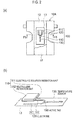
- Fig. 2 (a) is a developed plan view of the disposable diaper 10A in which the excretion detection device 100 is embedded.
- Fig. 2 (b) is a schematic illustration of the appearance of the excretion detection device 100.
- the disposable diaper 10A includes a topsheet 11, a backsheet 12, and an absorber 13.
- the topsheet 11 is in contact with the skin of the wearer W (living body).
- the topsheet 11 is configured from a material that allows liquids such as urine to pass through.
- the backsheet 12 is in contact with the clothing of the wearer W.
- the backsheet 12 is configured from a material that does not allow liquids to pass through.
- the absorber 13 absorbs bodily waste, such as urine or stool.
- the absorber 13 is configured from hydrophilic fibers such as ground pulp.
- the disposable diaper 10A can be manufactured according to a well-known method (for example, Japanese Unexamined Patent Publication No. JP2003-339771 ).
- the excretion detection device 100 is provided between the topsheet 11 and the absorber 13.
- the excretion detection device 100 may be provided between the backsheet 12 and the absorber 13, however, in order to be sure that the stool, which has a higher viscosity as compared to urine, is brought in contact with an electrode unit 120 of the excretion detection device 100, it is desired that the excretion detection device 100 be provided between the topsheet 11 and the absorber 13. Furthermore, even in the case of the open-type disposable diaper 10B, the excretion detection device 100 is desired to be provided between the topsheet 11 and the absorber 13.
- the disposable diaper 10B can be also manufactured according to a well-known method (for example, Japanese Patent Application Publication No. JP2005-58755 ).
- the excretion detection device 100 includes a solution and neutralizer retention unit 110, the electrode unit 120, a temperature sensor 130, and an active tag 150.
- the solution and neutralizer retention unit 110 has an electrolyte solution retention unit 111 and a neutralizer retention unit 112.
- the electrolyte solution retention unit 111 retains an electrolyte solution.
- the neutralizer retention unit 112 retains a neutralizer for reducing the hydrogen ion index (pH) of the bodily waste.
- the neutralizer retention unit 112 is provided adjacent to the electrolyte solution retention unit 111.
- the neutralizer retention unit 112 is provided adjacent to the upper side of the electrolyte solution retention unit 111.
- the electrode unit 120 is provided at the lower side of the electrolyte solution retention unit 111 (towards the absorber 13).
- the temperature sensor 130 is provided on the opposite side of an electrode 121 and an electrode 122, with the active tag 150 being disposed, as the reference, therebetween, in order to prevent coming in contact with the electrolyte solution seeping out from the electrolyte solution retention unit 111 and the neutralizer seeping out from the neutralizer retention unit 112.
- the electrode 121 and the electrode 122 are provided at a position where the electrodes can come in contact with the bodily waste from the wearer W and the electrolyte solution seeping out from the electrolyte solution retention unit 111. That is, the electrode 121 and the electrode 122 can be brought in contact with the electrolyte solution seeping out from the electrolyte solution retention unit 111 before the excretion of urine and the like.
- the active tag 150 is connected to the electrode unit 120 and the temperature sensor 130, and is provided at a position where the active tag 150 does not overlap the solution and neutralizer retention unit 110.
- Fig. 3 is a diagram showing the functional block configuration of the excretion detection device 100.
- the excretion detection device 100 includes the solution and neutralizer retention unit 110, the electrode unit 120, the temperature sensor 130, and the active tag 150.
- the active tag 150 is configured by a power supply unit 160, a control unit 170, and a radio transmission unit 180.
- the solution and neutralizer retention unit 110 has the electrolyte solution retention unit 111 and the neutralizer retention unit 112.
- the electrolyte solution retention unit 111 retains an electrolyte solution prepared by dissolving an electrolyte in a solvent such as water.
- the electrolyte solution retention unit 111 can use an aqueous solution including approx. 1 wt.% to 5 wt.% of sodium chloride (NaCl). That is, an NaCl aqueous solution similar to the urinary constituent is used as the electrolyte solution.
- the electrolyte solution retention unit 111 is a bag-shaped container that can store the liquid, and in the present embodiment, the electrolyte solution retention unit 111 is configured from a thermoplastic film of polyolefin.
- the electrolyte solution retention unit 111 By performing a predetermined operation for the electrolyte solution retention unit 111, for example, by pressing the electrolyte solution retention unit 111 from the topsheet 11 side, the electrolyte solution is made to seep out from the electrolyte solution retention unit 111. That is, by pressing the electrolyte solution retention unit 111, the bag-shaped electrolyte solution retention unit 111 configured from a thermoplastic film is torn, and the electrolyte solution seeps out near the periphery of the electrode unit 120. As a result, the electrolyte solution comes in contact with the electrode 121 and the electrode 122.
- the electrolyte solution retention unit 111 stores only solvents such as water, and powdered sodium chloride may be placed in the proximity of the electrolyte solution retention unit 111. In such a case, the powdered sodium chloride dissolves in the water seeping out from the electrolyte solution retention unit 111 to result in an electrolyte solution. This case also applies to a case where an electrolyte solution is retained by the electrolyte solution retention unit 111.
- the neutralizer retention unit 112 retains a neutralizer, such as citric acid, for reducing the pH of the bodily waste. Besides citric acid, tartaric acid and succinic acid may also be used as the neutralizer.
- the neutralizer retention unit 112 is provided at a position where the neutralizer can be in contact with the bodily waste. Specifically, the neutralizer retention unit 112 is provided to be positioned at the upper side of the electrode unit 120 (towards the backsheet 12) during the use of the excretion detection device 100.
- the neutralizer retention unit 112 is configured from a thermoplastic film of polyolefin. Furthermore, by performing a predetermined operation for the neutralizer retention unit 112, for example, by pressing the electrolyte solution retention unit 111 from the topsheet 11 side, the neutralizer is made to seep out from the neutralizer retention unit 112. That is, by pressing the neutralizer retention unit 112, the bag-shaped neutralizer retention unit 112 configured from a thermoplastic film is torn, and the neutralizer seeps out near the periphery of the bodily waste. As a result, the neutralizer comes in contact with the bodily waste. Therefore, the corrosion of the electrode 121 and the electrode 122 is prevented even when the bodily waste is urine with a high pH, for example.
- the electrode unit 120 is provided at a position where the electrode unit 120 can be in contact with the bodily waste. Specifically, the electrode unit 120 is provided at the lower side of the solution and neutralizer retention unit 110 (towards the absorber 13), and on the absorber 13.
- the pair of electrode 121 and electrode 122 configuring the electrode unit 120 are connected to the power supply unit 160.
- the electrode 121 and the electrode 122 are configured using materials having different ionization tendencies. In the present embodiment, a combination of aluminum and silver (each being a mixture combined with carbon) is used as the electrode 121 and the electrode 122.
- the power supply unit 160 having such an electrode unit 120 functions as a so-called voltaic cell through the interposition of the electrolyte solution or the bodily waste between the electrode 121 and the electrode 122.
- a voltaic cell is a cell that generates electric current by moving electrons through the immersion of electrodes using a metal with a large ionization tendency and a metal with a small ionization tendency, in an electrolyte solution.
- the electrode 121 and the electrode 122 can be brought in contact with the electrolyte solution seeping out from the electrolyte solution retention unit 111 before the excretion of urine and the like. Therefore, a difference in potential occurs between the electrode 121 and the electrode 122 due to the electrolyte solution prior to excretion, and due to the electrolyte solution or the bodily waste after excretion, and electromotive force is obtained.
- the temperature sensor 130 is configured to detect the environmental information that changes as a result of excretion from the wearer W. Specifically, in the disposable diaper 10A, the temperature sensor 130 detects the temperature of the region where the bodily waste is excreted (the region in which the absorber 13 is provided) as the environment information. The temperature sensor 130 is operated by the electric power generated by the power supply unit 160.
- a thin-film thermistor (hereinafter, thermistor) is used as the temperature sensor 130.
- thermistor a thin-film thermistor
- a synthetic-resin film on which the electrode for detecting urine or stool, and the electrode for supplying electric power to the thermistor are marked by a conductive ink is used.
- the active tag 150 is an active-type IC tag with which the electrode unit 120 and the temperature sensor 130 are connected. That is, the active tag 150 can transmit a radio signal without depending on another radio communication device, for example.
- the power supply unit 160 has an electrification circuit 161 and an electricity-storage circuit 162.
- the electrode 121 and the electrode 122 are connected to the electrification circuit 161.
- the electrification circuit 161 is electrified due to the difference in potential that occurs between the electrode 121 and the electrode 122, and stores the generated electric power in the electricity-storage circuit 162.
- the electricity-storage circuit 162 is configured from a capacitor, for example.
- the control unit 170 is operated by the electric power generated by the power supply unit 160. Specifically, based on the value output from the temperature sensor 130, the control unit 170 generates data indicating the temperature information, and then outputs the generated data to the radio transmission unit 180.
- the radio transmission unit 180 is operated by the electric power generated by the power supply unit 160.
- the radio transmission unit 180 notifies the temperature information detected by the temperature sensor 130 to outside the excretion detection device 100.
- the radio transmission unit 180 configures a notification unit configured to notify excretion from the wearer to outside the excretion detection device 100.
- the radio transmission unit 180 transmits a radio signal including the data indicating the temperature information towards the radio relay station 20.
- the radio transmission unit 180 repetitively transmits radio signals at a predetermined period (for example, 10 seconds).
- the excretion detection device 100 functions as a voltaic cell before and after excretion, the excretion detection device 100 is a battery-less type device in which a battery is not loaded for operating the temperature sensor 130, the control unit 170, and the radio transmission unit 180.
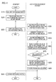
- Fig. 4 shows the excretion management flow using the aforementioned excretion management system 1. Specifically, Fig. 4 shows the flow from the detection of urination or defecation, by the excretion detection device 100, from the wearer W wearing the disposable diaper 10A (or the disposable diaper 10B), up to the transmission of an email notifying the cellular phone terminal 50 and the personal computer 60 of this effect.
- step S10 a guardian and a caretaker (hereinafter, assistant) assisting subjects such as care-receivers in wearing the disposable diaper 10A to take out the disposable diaper 10A from the package, for example.
- assistant assisting subjects such as care-receivers in wearing the disposable diaper 10A to take out the disposable diaper 10A from the package, for example.
- step S20 the assistant presses the solution and neutralizer retention unit 110 embedded at the lower side of the topsheet 11 of the disposable diaper 10A.
- the bag-shaped electrolyte solution retention unit 111 and the neutralizer retention unit 112 are torn.
- step S30 the electrolyte solution (sodium chloride solution) seeps out from the electrolyte solution retention unit 111 near the periphery of the electrode unit 120. Furthermore, the neutralizer seeps out from the neutralizer retention unit 112 near the periphery of the electrode unit 120.
- FIG. 5 is a schematic cross-sectional view of the disposable diaper 10A along an F5-F5 line of Fig. 2 .
- the bag-shaped electrolyte solution retention unit 111 and the neutralizer retention unit 112 are torn.
- an electrolyte solution WT retained in the electrolyte solution retention unit 111 seeps out near the periphery of the electrode 121 and the electrode 122.
- a neutralizer N for example, citric acid
- step S35 the assistant puts on the disposable diaper 10A to the subject, such as an infant or toddler.
- the task of putting on the disposable diaper 10A by the assistant is thus complete.
- step S40 the power supply unit 160 (electrification circuit 161) is electrified due to the interposition of the electrolyte solution between the electrode 121 and the electrode 122, and generates electric power.
- step S50 the excretion detection device 100 starts operating as a result of the electric power generated by the power supply unit 160.
- step S60 the radio transmission unit 180 periodically transmits the temperature information acquired by the temperature sensor 130 to the excretion management server 40. Specifically, as described above, the radio transmission unit 180 transmits the temperature information to the excretion management server 40 via the radio relay station 20 and the radio base station 30.
- step S70 based on the received temperature information, the excretion management server 40 determines whether or not the temperature change pattern matches the already-stored pattern.
- the excretion management server 40 stores the temperature change pattern that occurs as a result of urination, and the temperature change pattern that occurs as a result of defecation.
- the excretion management server 40 identifies urination and defecation.
- step S80 the excretion management server 40 transmits an email indicating the occurrence of urination or defecation to a pre-registered address (the cellular phone terminal 50 and the personal computer 60).
- the neutralizer (citric acid) that has seeped out near the periphery of the electrode 121 and the electrode 122 reduces the pH of the bodily waste (for example, urine), and neutralizes alkalinity of the bodily waste.
- the neutralizer N that has seeped out near the periphery of the electrode 121 and the electrode 122 comes in contact with the bodily waste Ex.
- the alkalinity of the bodily waste Ex is neutralized by the neutralizer N.
- step 90 as a result of receipt of the email, the assistant of the wearer W quickly recognizes urination and defecation by the wearer W, and changes the disposable diaper.
- the assistant In order to prevent interference between the radio signal transmitted by the excretion detection device 100 embedded in the disposable diaper after use, and the radio signal transmitted by the excretion detection device 100 embedded in the new disposable diaper after change, the assistant must take away the disposable diaper after use by more than a fixed distance from the radio relay station 20.
- the neutralizer retention unit 112 is provided at a position where the neutralizer can be in contact with the bodily waste. Specifically, the neutralizer retention unit 112 is provided at the upper side of the electrode unit 120 (electrode 121 and electrode 122). Furthermore, as a result of pressing of the neutralizer retention unit 112, the neutralizer seeps out near the periphery of the electrode unit 120, and the neutralizer comes in contact with the bodily waste. Therefore, the alkalinity of the bodily waste Ex can be neutralized by the neutralizer N.
- the fast corrosion of the electrode unit 120 by urine can be prevented even in a disposable diaper for elderly persons whose pH of urine is often high due to urinary tract infections and the like.
- Materials such as gold, silver, copper, zinc, aluminum, iron, and carbon, and mixtures of these materials have been disclosed in the prior art documents as materials for electrodes, and the use of two different materials with a large difference in ionization tendencies is highly effective in obtaining the electromotive force.
- a combination of aluminum and silver is desired from the viewpoint of safety and the manufacturing cost, as mentioned in the present embodiment.
- aluminum is an amphoteric element, and can be dissolved in both acid and alkali. Therefore, as shown below, generally, a lytic reaction with aluminum occurs in a strong base solution.
- the manufacturing cost also does not increase substantially. Furthermore, because the time until when the aluminum configuring the electrode 121 and the electrode 122 dissolves is prolonged, a sufficient electrification time can be secured even in the case of contact with urine with a high pH.
- the electrode unit 120 is provided at a position where the electrode unit 120 can be in contact with the bodily waste of the wearer W and the electrolyte solution retained by the electrolyte solution retention unit 111. Additionally, the electrode unit 120 can also be contact with the electrolyte solution before excretion by the wearer W. Therefore, electrification by the power supply unit 160 is possible even before urination and defecation.
- the neutralizer retention unit 112 is provided at the upper side of the electrolyte solution retention unit 111, however, the positions of the electrolyte solution retention unit 111 and the neutralizer retention unit 112 may be exchanged.
- the neutralizer retention unit 112 may also be provided adjacent to the electrolyte solution retention unit 111, in a plan view (see Fig. 2 (a) ) of the absorber 13 such that the neutralizer retention unit 112 does not overlap the electrolyte solution retention unit 111.
- the electrolyte solution retention unit 111 need not necessarily be provided.
- the temperature information is transmitted by using the radio transmission unit 180, however, rather than transmitting the temperature information by the radio transmission unit 180, an alarm such as a buzzer may be operated.
- the electrolyte solution retention unit 111 is torn by pressing the electrolyte solution retention unit 111 from the topsheet 11 side, and the electrolyte solution is made to seep out from the electrolyte solution retention unit 111, however, the electrolyte solution may be made to seep out by performing an operation other than pressing.
- the electrolyte solution retention unit 111 may be torn by pulling thread-like members connected to the electrolyte solution retention unit 111.
- the excretion detection device 100 is not just loaded in a diaper, but may also be loaded in an absorbent article such as a sanitary napkin. Additionally, the absorbent article is not just used for human beings, but may also be used for animals, such as pets.
- an excretion detection device by which a sufficient electrification time can be secured even in the case of contact with urine with a high pH, without increasing the manufacturing cost substantially, and also to provide an absorbent article having such an excretion detection device.
Landscapes
- Health & Medical Sciences (AREA)
- Epidemiology (AREA)
- Engineering & Computer Science (AREA)
- Biomedical Technology (AREA)
- Heart & Thoracic Surgery (AREA)
- Vascular Medicine (AREA)
- Life Sciences & Earth Sciences (AREA)
- Animal Behavior & Ethology (AREA)
- General Health & Medical Sciences (AREA)
- Public Health (AREA)
- Veterinary Medicine (AREA)
- Nursing (AREA)
- Orthopedic Medicine & Surgery (AREA)
- Absorbent Articles And Supports Therefor (AREA)
- Orthopedics, Nursing, And Contraception (AREA)
- Investigating Or Analyzing Materials By The Use Of Electric Means (AREA)
Abstract
Description
- The present invention relates to an excretion detection device, by which the excretion of bodily waste from a living body is detected, and an absorbent article including such an excretion detection device.
- As regards the absorbent article such as a disposable diaper, an excretion detection device configured to detect the excretion of urine or stool from a wearer (living body) of the absorbent article is known. The excretion detection device is loaded in the absorbent article, and upon detection of the excretion of urine or stool from the wearer, the excretion detection device reports the excretion to the outside.
- In such an excretion detection device, a method of electrification, by bringing the bodily waste of the wearer in contact with electrodes configured from materials having different ionization tendencies, is known. That is, there has been proposed a device configured to actuate an alarm such as a buzzer by making use of the principle of a voltaic cell rather than using a battery (see
Patent Document 1 and Patent Document 2). - In the excretion detection device disclosed in
Patent Document 1, copper or zinc is used as materials of the electrodes. Furthermore, in the excretion detection device disclosed in Patent Document 2, there are described that electrification through the use of the bodily waste (urine) and a battery are put to use together, and gold, silver, copper, or aluminum can be used as materials of the electrodes. -
- [PATENT DOCUMENT 1]: Japanese Patent Application Publication No.
2002-277435 Fig. 4 ) - [PATENT DOCUMENT 2]: Japanese Patent Application Publication No.
2006-296566 Fig. 1 ) - However, the aforementioned conventional excretion detection device has the following problem. That is, although the electrodes are in contact with the bodily waste of the wearer, if the pH of the bodily waste is high, corrosion of the electrodes speeds up. Particularly, the pH of urine of elderly persons is often high due to urinary tract infections and the like, and therefore, when the electrodes come in contact with such urine having a high pH, the electrodes corrode fast, and a sufficient electrification time cannot be secured, which is a point of concern.
- Though the use of electrodes with high corrosion resistance is thought of, from the viewpoint of the use of such electrodes in sanitary products as well as the manufacturing cost, this is not a practical solution.
- Therefore, an object of the present invention is to provide an excretion detection device by which a sufficient electrification time can be secured even in the case of contact with urine with a high pH, without significantly increasing the manufacturing cost, and also to provide an absorbent article having such an excretion detection device.
- In order to solve the above-mentioned problem, the present invention has the following characteristics. The characteristic of the present invention is an excretion detection device (excretion detection device 10) configured to detect excretion of bodily waste (bodily waste Ex, e.g., urine and stool) from a living body (wearer W), comprising: a power supply unit (power supply unit 160) having electrodes (
electrode 121, electrode 122) configured by using materials with different ionization tendencies; a neutralizer retention unit (neutralizer retention unit 112) configured to retain a neutralizer (neutralizer N) for reducing the hydrogen ion index of the bodily waste; and a notification unit (radio transmission unit 180) operated by the electric power generated by the power supply unit, and configured to notify the excretion from the living body to outside the excretion detection device, wherein the electrodes are provided at a position where the electrodes can be in contact with the bodily waste, and the neutralizer retention unit is provided at a position where the neutralizer can be in contact with the bodily waste. - According to the above-mentioned characteristic of the present invention, the excretion detection device preferably comprises a solution retention unit (electrolyte solution retention unit 111) configured to retain an electrolyte solution (electrolyte solution WT), wherein the electrodes are provided at a position where the electrodes can be in contact with the bodily waste and the electrolyte solution, and can also be in contact with the electrolyte solution before the excretion of the bodily waste.
- According to the above-mentioned characteristic of the present invention, the neutralizer retention unit is preferably provided so as to be positioned at the upper side of the electrodes during the use of the excretion detection device.
- According to the above-mentioned characteristic of the present invention, the neutralizer retention unit is preferably adjacent to the solution retention unit.
- According to the above-mentioned characteristic of the present invention, the neutralizer is preferably made to seep out from the neutralizer retention unit by performing a predetermined operation for the neutralizer retention unit, and the neutralizer is brought in contact with the bodily waste.
- According to the above-mentioned characteristic of the present invention, the electrolyte solution is preferably made to seep out from the solution retention unit by performing a predetermined operation (e.g., pressing) for the solution retention unit, and the electrolyte solution is brought in contact with the electrodes.
- According to the above-mentioned characteristic of the present invention, an absorbent article (e.g.,
disposable diaper 10A) worn by a living body and configured to absorb the bodily waste from the living body, wherein the absorbent article includes an excretion detection device configured to detect the excretion of the bodily waste, and the excretion detection device comprises: a power supply unit having electrodes configured by using materials with different ionization tendencies; a neutralizer retention unit configured to retain a neutralizer for reducing the hydrogen ion index of the bodily waste; and a notification unit operated by the electric power generated by the power supply unit, and configured to notify excretion from the living body to outside the excretion detection device, wherein the electrodes are provided at a position where the electrodes can be in contact with the bodily waste, and the neutralizer retention unit is provided at a position where the neutralizer can be in contact with the bodily waste. - According to the above-mentioned characteristic of the present invention, the absorbent article preferably comprises: a topsheet (topsheet 11) that is in contact with the living body and allows the passage of liquids; and an absorber (absorber 13) configured to absorb the bodily waste, and the excretion detection device is provided between the topsheet and the absorber.
- According to the characteristic of the present invention, it is possible to provide an excretion detection device by which a sufficient electrification time can be secured even in the case of contact with urine with a high pH, without increasing the manufacturing cost substantially, and also to provide an absorbent article having such an excretion detection device.
-
- [
Fig. 1] Fig. 1 is a diagram showing an entire schematic configuration of anexcretion management system 1 according to an embodiment of the present invention. - [
Fig. 2] Fig. 2 is a developed plan view of adisposable diaper 10A in which anexcretion detection device 100 according to the embodiment of the present invention is embedded, and is also a schematic illustration of the appearance of theexcretion detection device 100. - [
Fig. 3] Fig. 3 is a diagram showing a functional block configuration of theexcretion detection device 100 according to the embodiment of the present invention. - [
Fig. 4] Fig. 4 is a diagram showing the excretion management flow using theexcretion management system 1 according to the embodiment of the present invention. - [
Fig. 5] Fig. 5 is a schematic cross-sectional view of thedisposable diaper 10A along an F5-F5 line ofFig. 2 . - Next, an embodiment of an excretion detection device and an absorbent article according to the present invention will be described with reference to drawings. In the following description of the drawings, the same or similar reference numerals are used to designate the same or similar parts. It will be appreciated that the drawings are schematically shown and the ratio and the like of each dimension are different from the real ones.
- Accordingly, specific dimensions should be determined in consideration of the explanation below. Moreover, among the drawings, the respective dimensional relations or ratios may differ.
-
Fig. 1 is a diagram showing an entire schematic configuration of anexcretion management system 1 according to the present embodiment.
As shown inFig. 1 , theexcretion management system 1 is configured by aradio relay station 20, anexcretion management server 40, and anexcretion detection device 100. - A
disposable diaper 10A and adisposable diaper 10B are absorbent articles worn by a wearer W (living body), and to absorb a bodily waste such as urine or stool from the wearer W. Thedisposable diaper 10A and thedisposable diaper 10B are equipped with theexcretion detection device 100 configured to detect excretion of bodily waste. Specifically, theexcretion detection device 100 is loaded in an open-type (tape-type)disposable diaper 10A and a pant-typedisposable diaper 10B. - The
excretion detection device 100 detects the excretion of bodily waste from the wearer W. Theexcretion detection device 100 is configured by an active-type IC tag that can transmit a radio signal to theradio relay station 20, a temperature sensor, and the like, and repetitively transmits a radio signal including the temperature information (environment information) within the disposable diaper, at a predetermined period. The detailed configuration of theexcretion detection device 100 is described later. - The
radio relay station 20 converts the radio signal received from theexcretion detection device 100 to a radio signal in accordance with a predetermined communication system. In the present embodiment, theradio relay station 20 converts the radio signal received from theexcretion detection device 100 to a radio signal of the Personal Handy-phone (PHS system), and then transmits the radio signal to aradio base station 30. Theradio relay station 20 is a rectangular parallelepiped with one side of a few centimeters or less, which can be installed in the bed as a name tag, and can be installed on to the wearer W. In order to maintain radio communication between theradio relay station 20 and theexcretion detection device 100, theradio relay station 20 and theexcretion detection device 100 must be positioned within a fixed distance. - The
radio base station 30 is configured to receive a radio signal from theradio relay station 20. In the present embodiment, theradio base station 30 transmits and receives a radio signal in accordance with the PHS system. Theradio base station 30 is connected to theexcretion management server 40 via a wire communication network (not shown in the figure). - The
excretion management server 40 stores a plurality of change patterns of the environmental information (such as the temperature, humidity, and odor) concerning urination and defecation. Theexcretion management server 40 determines the existence or non-existence of urination or defecation by the wearer W based on the temperature information transmitted repetitively from theexcretion detection device 100 via theradio relay station 20 and theradio base station 30. Upon determining the occurrence of urination or defecation, theexcretion management server 40 transmits an email indicating the excretion to a pre-registeredcellular phone terminal 50 and apersonal computer 60. When theexcretion management server 40 transmits such an email to a pre-registered address in thecellular phone terminal 50 and thepersonal computer 60, a guardian (caretaker) of the wearer W, who checks the email can quickly take an appropriate measure, such as changing the disposable diaper. -
Fig. 2 (a) is a developed plan view of thedisposable diaper 10A in which theexcretion detection device 100 is embedded.Fig. 2 (b) is a schematic illustration of the appearance of theexcretion detection device 100. - As shown in
Fig. 2 (a) , thedisposable diaper 10A includes atopsheet 11, abacksheet 12, and anabsorber 13. Thetopsheet 11 is in contact with the skin of the wearer W (living body). Thetopsheet 11 is configured from a material that allows liquids such as urine to pass through. Thebacksheet 12 is in contact with the clothing of the wearer W. Thebacksheet 12 is configured from a material that does not allow liquids to pass through. Theabsorber 13 absorbs bodily waste, such as urine or stool. Theabsorber 13 is configured from hydrophilic fibers such as ground pulp. Thedisposable diaper 10A can be manufactured according to a well-known method (for example, Japanese Unexamined Patent Publication No.JP2003-339771 - The
excretion detection device 100 is provided between thetopsheet 11 and theabsorber 13. Theexcretion detection device 100 may be provided between thebacksheet 12 and theabsorber 13, however, in order to be sure that the stool, which has a higher viscosity as compared to urine, is brought in contact with anelectrode unit 120 of theexcretion detection device 100, it is desired that theexcretion detection device 100 be provided between thetopsheet 11 and theabsorber 13. Furthermore, even in the case of the open-typedisposable diaper 10B, theexcretion detection device 100 is desired to be provided between thetopsheet 11 and theabsorber 13. Thedisposable diaper 10B can be also manufactured according to a well-known method (for example, Japanese Patent Application Publication No.JP2005-58755 - The
excretion detection device 100 includes a solution andneutralizer retention unit 110, theelectrode unit 120, atemperature sensor 130, and anactive tag 150. The solution andneutralizer retention unit 110 has an electrolytesolution retention unit 111 and aneutralizer retention unit 112. The electrolytesolution retention unit 111 retains an electrolyte solution. Theneutralizer retention unit 112 retains a neutralizer for reducing the hydrogen ion index (pH) of the bodily waste. In the present embodiment, theneutralizer retention unit 112 is provided adjacent to the electrolytesolution retention unit 111. Specifically, theneutralizer retention unit 112 is provided adjacent to the upper side of the electrolytesolution retention unit 111. - The
electrode unit 120 is provided at the lower side of the electrolyte solution retention unit 111 (towards the absorber 13). Thetemperature sensor 130 is provided on the opposite side of anelectrode 121 and anelectrode 122, with theactive tag 150 being disposed, as the reference, therebetween, in order to prevent coming in contact with the electrolyte solution seeping out from the electrolytesolution retention unit 111 and the neutralizer seeping out from theneutralizer retention unit 112. Theelectrode 121 and theelectrode 122 are provided at a position where the electrodes can come in contact with the bodily waste from the wearer W and the electrolyte solution seeping out from the electrolytesolution retention unit 111. That is, theelectrode 121 and theelectrode 122 can be brought in contact with the electrolyte solution seeping out from the electrolytesolution retention unit 111 before the excretion of urine and the like. - The
active tag 150 is connected to theelectrode unit 120 and thetemperature sensor 130, and is provided at a position where theactive tag 150 does not overlap the solution andneutralizer retention unit 110. -
Fig. 3 is a diagram showing the functional block configuration of theexcretion detection device 100. As shown inFig. 3 , theexcretion detection device 100 includes the solution andneutralizer retention unit 110, theelectrode unit 120, thetemperature sensor 130, and theactive tag 150. Furthermore, theactive tag 150 is configured by apower supply unit 160, acontrol unit 170, and aradio transmission unit 180. - As described above, the solution and
neutralizer retention unit 110 has the electrolytesolution retention unit 111 and theneutralizer retention unit 112. - The electrolyte
solution retention unit 111 retains an electrolyte solution prepared by dissolving an electrolyte in a solvent such as water. For example, the electrolytesolution retention unit 111 can use an aqueous solution including approx. 1 wt.% to 5 wt.% of sodium chloride (NaCl). That is, an NaCl aqueous solution similar to the urinary constituent is used as the electrolyte solution. The electrolytesolution retention unit 111 is a bag-shaped container that can store the liquid, and in the present embodiment, the electrolytesolution retention unit 111 is configured from a thermoplastic film of polyolefin. - By performing a predetermined operation for the electrolyte
solution retention unit 111, for example, by pressing the electrolytesolution retention unit 111 from thetopsheet 11 side, the electrolyte solution is made to seep out from the electrolytesolution retention unit 111. That is, by pressing the electrolytesolution retention unit 111, the bag-shaped electrolytesolution retention unit 111 configured from a thermoplastic film is torn, and the electrolyte solution seeps out near the periphery of theelectrode unit 120. As a result, the electrolyte solution comes in contact with theelectrode 121 and theelectrode 122. - The electrolyte
solution retention unit 111 stores only solvents such as water, and powdered sodium chloride may be placed in the proximity of the electrolytesolution retention unit 111. In such a case, the powdered sodium chloride dissolves in the water seeping out from the electrolytesolution retention unit 111 to result in an electrolyte solution. This case also applies to a case where an electrolyte solution is retained by the electrolytesolution retention unit 111. - The
neutralizer retention unit 112 retains a neutralizer, such as citric acid, for reducing the pH of the bodily waste. Besides citric acid, tartaric acid and succinic acid may also be used as the neutralizer. Theneutralizer retention unit 112 is provided at a position where the neutralizer can be in contact with the bodily waste. Specifically, theneutralizer retention unit 112 is provided to be positioned at the upper side of the electrode unit 120 (towards the backsheet 12) during the use of theexcretion detection device 100. - Same as the electrolyte
solution retention unit 111, theneutralizer retention unit 112 is configured from a thermoplastic film of polyolefin. Furthermore, by performing a predetermined operation for theneutralizer retention unit 112, for example, by pressing the electrolytesolution retention unit 111 from thetopsheet 11 side, the neutralizer is made to seep out from theneutralizer retention unit 112. That is, by pressing theneutralizer retention unit 112, the bag-shapedneutralizer retention unit 112 configured from a thermoplastic film is torn, and the neutralizer seeps out near the periphery of the bodily waste. As a result, the neutralizer comes in contact with the bodily waste. Therefore, the corrosion of theelectrode 121 and theelectrode 122 is prevented even when the bodily waste is urine with a high pH, for example. - The
electrode unit 120 is provided at a position where theelectrode unit 120 can be in contact with the bodily waste. Specifically, theelectrode unit 120 is provided at the lower side of the solution and neutralizer retention unit 110 (towards the absorber 13), and on theabsorber 13. The pair ofelectrode 121 andelectrode 122 configuring theelectrode unit 120 are connected to thepower supply unit 160. Theelectrode 121 and theelectrode 122 are configured using materials having different ionization tendencies. In the present embodiment, a combination of aluminum and silver (each being a mixture combined with carbon) is used as theelectrode 121 and theelectrode 122. That is, thepower supply unit 160 having such anelectrode unit 120 functions as a so-called voltaic cell through the interposition of the electrolyte solution or the bodily waste between theelectrode 121 and theelectrode 122. A voltaic cell is a cell that generates electric current by moving electrons through the immersion of electrodes using a metal with a large ionization tendency and a metal with a small ionization tendency, in an electrolyte solution. - As described above, the
electrode 121 and theelectrode 122 can be brought in contact with the electrolyte solution seeping out from the electrolytesolution retention unit 111 before the excretion of urine and the like. Therefore, a difference in potential occurs between theelectrode 121 and theelectrode 122 due to the electrolyte solution prior to excretion, and due to the electrolyte solution or the bodily waste after excretion, and electromotive force is obtained. - The
temperature sensor 130 is configured to detect the environmental information that changes as a result of excretion from the wearer W. Specifically, in thedisposable diaper 10A, thetemperature sensor 130 detects the temperature of the region where the bodily waste is excreted (the region in which theabsorber 13 is provided) as the environment information. Thetemperature sensor 130 is operated by the electric power generated by thepower supply unit 160. - In the present embodiment, a thin-film thermistor (hereinafter, thermistor) is used as the
temperature sensor 130. In thetemperature sensor 130, a synthetic-resin film on which the electrode for detecting urine or stool, and the electrode for supplying electric power to the thermistor are marked by a conductive ink is used. A thermistor that is easily affected by the surrounding temperature at which the heat capacity is less, for example, the ET-103 thermistor manufactured by SEMITEC CORPORATION, is desired to be used as thetemperature sensor 130. - The
active tag 150 is an active-type IC tag with which theelectrode unit 120 and thetemperature sensor 130 are connected. That is, theactive tag 150 can transmit a radio signal without depending on another radio communication device, for example. - The
power supply unit 160 has anelectrification circuit 161 and an electricity-storage circuit 162. Theelectrode 121 and theelectrode 122 are connected to theelectrification circuit 161. Theelectrification circuit 161 is electrified due to the difference in potential that occurs between theelectrode 121 and theelectrode 122, and stores the generated electric power in the electricity-storage circuit 162. The electricity-storage circuit 162 is configured from a capacitor, for example. - The
control unit 170 is operated by the electric power generated by thepower supply unit 160. Specifically, based on the value output from thetemperature sensor 130, thecontrol unit 170 generates data indicating the temperature information, and then outputs the generated data to theradio transmission unit 180. - The
radio transmission unit 180 is operated by the electric power generated by thepower supply unit 160. Theradio transmission unit 180 notifies the temperature information detected by thetemperature sensor 130 to outside theexcretion detection device 100. In the present embodiment, theradio transmission unit 180 configures a notification unit configured to notify excretion from the wearer to outside theexcretion detection device 100. - Specifically, the
radio transmission unit 180 transmits a radio signal including the data indicating the temperature information towards theradio relay station 20. In the present embodiment, theradio transmission unit 180 repetitively transmits radio signals at a predetermined period (for example, 10 seconds). - As described above, because the
excretion detection device 100 functions as a voltaic cell before and after excretion, theexcretion detection device 100 is a battery-less type device in which a battery is not loaded for operating thetemperature sensor 130, thecontrol unit 170, and theradio transmission unit 180. -
Fig. 4 shows the excretion management flow using the aforementionedexcretion management system 1. Specifically,Fig. 4 shows the flow from the detection of urination or defecation, by theexcretion detection device 100, from the wearer W wearing thedisposable diaper 10A (or thedisposable diaper 10B), up to the transmission of an email notifying thecellular phone terminal 50 and thepersonal computer 60 of this effect. - As shown in
Fig. 4 , in step S10, a guardian and a caretaker (hereinafter, assistant) assisting subjects such as care-receivers in wearing thedisposable diaper 10A to take out thedisposable diaper 10A from the package, for example. - In step S20, the assistant presses the solution and
neutralizer retention unit 110 embedded at the lower side of thetopsheet 11 of thedisposable diaper 10A. As a result of such an operation by the assistant, the bag-shaped electrolytesolution retention unit 111 and theneutralizer retention unit 112 are torn. - In step S30, the electrolyte solution (sodium chloride solution) seeps out from the electrolyte
solution retention unit 111 near the periphery of theelectrode unit 120. Furthermore, the neutralizer seeps out from theneutralizer retention unit 112 near the periphery of theelectrode unit 120. - Here, the state in which the electrolyte solution and the neutralizer seep out near the periphery of the
electrode unit 120 is explained with reference toFig. 5. Fig. 5 is a schematic cross-sectional view of thedisposable diaper 10A along an F5-F5 line ofFig. 2 . As shown inFig. 5 , when a portion of the solution andneutralizer retention unit 110 is pressed, the bag-shaped electrolytesolution retention unit 111 and theneutralizer retention unit 112 are torn. As a result, an electrolyte solution WT retained in the electrolytesolution retention unit 111 seeps out near the periphery of theelectrode 121 and theelectrode 122. Similarly, a neutralizer N (for example, citric acid) retained in theneutralizer retention unit 112 seeps out near the periphery of theelectrode 121 and theelectrode 122. - In step S35, the assistant puts on the
disposable diaper 10A to the subject, such as an infant or toddler. The task of putting on thedisposable diaper 10A by the assistant is thus complete. - In step S40, the power supply unit 160 (electrification circuit 161) is electrified due to the interposition of the electrolyte solution between the
electrode 121 and theelectrode 122, and generates electric power. - In step S50, the
excretion detection device 100 starts operating as a result of the electric power generated by thepower supply unit 160. - In step S60, the
radio transmission unit 180 periodically transmits the temperature information acquired by thetemperature sensor 130 to theexcretion management server 40. Specifically, as described above, theradio transmission unit 180 transmits the temperature information to theexcretion management server 40 via theradio relay station 20 and theradio base station 30. - In step S70, based on the received temperature information, the
excretion management server 40 determines whether or not the temperature change pattern matches the already-stored pattern. In the present embodiment, theexcretion management server 40 stores the temperature change pattern that occurs as a result of urination, and the temperature change pattern that occurs as a result of defecation. - For example, if a temperature change pattern during defecation is compared with that during urination, the rise in the temperature is sharper during urination, and the convergence of temperature change is also faster, as compared to defecation. On the other hand, the rise in the temperature is slow during defecation, and the convergence of temperature change is also slow. Based on such differences in the temperature change pattern, the
excretion management server 40 identifies urination and defecation. - When the temperature change pattern based on the received temperature information matches the temperature change pattern of urination or defecation (YES in step S70), then in step S80, the
excretion management server 40 transmits an email indicating the occurrence of urination or defecation to a pre-registered address (thecellular phone terminal 50 and the personal computer 60). - Furthermore, in step S85, the neutralizer (citric acid) that has seeped out near the periphery of the
electrode 121 and theelectrode 122 reduces the pH of the bodily waste (for example, urine), and neutralizes alkalinity of the bodily waste. Specifically, as shown inFig. 5 , when a bodily waste Ex passes through thetopsheet 11 and is absorbed by theabsorber 13, the neutralizer N that has seeped out near the periphery of theelectrode 121 and theelectrode 122 comes in contact with the bodily waste Ex. As a result, the alkalinity of the bodily waste Ex is neutralized by the neutralizer N. - In
step 90, as a result of receipt of the email, the assistant of the wearer W quickly recognizes urination and defecation by the wearer W, and changes the disposable diaper. In order to prevent interference between the radio signal transmitted by theexcretion detection device 100 embedded in the disposable diaper after use, and the radio signal transmitted by theexcretion detection device 100 embedded in the new disposable diaper after change, the assistant must take away the disposable diaper after use by more than a fixed distance from theradio relay station 20. - According to the
excretion detection device 100 explained above, theneutralizer retention unit 112 is provided at a position where the neutralizer can be in contact with the bodily waste. Specifically, theneutralizer retention unit 112 is provided at the upper side of the electrode unit 120 (electrode 121 and electrode 122). Furthermore, as a result of pressing of theneutralizer retention unit 112, the neutralizer seeps out near the periphery of theelectrode unit 120, and the neutralizer comes in contact with the bodily waste. Therefore, the alkalinity of the bodily waste Ex can be neutralized by the neutralizer N. - Thus, the fast corrosion of the
electrode unit 120 by urine can be prevented even in a disposable diaper for elderly persons whose pH of urine is often high due to urinary tract infections and the like. Materials such as gold, silver, copper, zinc, aluminum, iron, and carbon, and mixtures of these materials have been disclosed in the prior art documents as materials for electrodes, and the use of two different materials with a large difference in ionization tendencies is highly effective in obtaining the electromotive force. However, in view of using the electrodes in a disposable diaper, a combination of aluminum and silver is desired from the viewpoint of safety and the manufacturing cost, as mentioned in the present embodiment. - However, aluminum is an amphoteric element, and can be dissolved in both acid and alkali. Therefore, as shown below, generally, a lytic reaction with aluminum occurs in a strong base solution.
-
2 Al + 10 H2O + 2 OH- → 2 [Al(OH)4(H2O)2]- + 3 H2
Particularly, in elderly persons, for example, when the pH of urine becomes high due to urinary tract infections and the like, aluminum gets dissolved. According to the aforementionedexcretion detection device 100, even in such cases, the time until when aluminum gets dissolved can be prolonged. - That is, according to the
excretion detection device 100, because relatively low-cost and safe aluminum is used primarily in theelectrode 121 and theelectrode 122, the manufacturing cost also does not increase substantially. Furthermore, because the time until when the aluminum configuring theelectrode 121 and theelectrode 122 dissolves is prolonged, a sufficient electrification time can be secured even in the case of contact with urine with a high pH. - In the present embodiment, the
electrode unit 120 is provided at a position where theelectrode unit 120 can be in contact with the bodily waste of the wearer W and the electrolyte solution retained by the electrolytesolution retention unit 111. Additionally, theelectrode unit 120 can also be contact with the electrolyte solution before excretion by the wearer W. Therefore, electrification by thepower supply unit 160 is possible even before urination and defecation. - So far, the present invention is disclosed through the above embodiments. However, it should not be interpreted that the statements and drawings constituting a part of the present disclosure limit the present invention. From this disclosure, a variety of alternate embodiments, examples, and applicable techniques will become apparent to one skilled in the art.
- For example, in the aforementioned embodiment, the
neutralizer retention unit 112 is provided at the upper side of the electrolytesolution retention unit 111, however, the positions of the electrolytesolution retention unit 111 and theneutralizer retention unit 112 may be exchanged. Alternatively, theneutralizer retention unit 112 may also be provided adjacent to the electrolytesolution retention unit 111, in a plan view (seeFig. 2 (a) ) of theabsorber 13 such that theneutralizer retention unit 112 does not overlap the electrolytesolution retention unit 111. Furthermore, the electrolytesolution retention unit 111 need not necessarily be provided. - In the aforementioned embodiment, the temperature information is transmitted by using the
radio transmission unit 180, however, rather than transmitting the temperature information by theradio transmission unit 180, an alarm such as a buzzer may be operated. - In the aforementioned embodiment, the electrolyte
solution retention unit 111 is torn by pressing the electrolytesolution retention unit 111 from thetopsheet 11 side, and the electrolyte solution is made to seep out from the electrolytesolution retention unit 111, however, the electrolyte solution may be made to seep out by performing an operation other than pressing. For example, the electrolytesolution retention unit 111 may be torn by pulling thread-like members connected to the electrolytesolution retention unit 111. - Furthermore, the
excretion detection device 100 is not just loaded in a diaper, but may also be loaded in an absorbent article such as a sanitary napkin. Additionally, the absorbent article is not just used for human beings, but may also be used for animals, such as pets. - As described above, needless to say, the present invention includes various embodiments and the like not described here. Therefore, the technical range of the present invention is to be defined only by the inventive specific matter according to the adequate claims from the above description.
- The entire contents of Japanese Patent Application No.
2010-009301 (filed on January 19, 2010 - As described above, according to the present invention, it is possible to provide an excretion detection device by which a sufficient electrification time can be secured even in the case of contact with urine with a high pH, without increasing the manufacturing cost substantially, and also to provide an absorbent article having such an excretion detection device.
-
- 1: excretion management system, 10A, 10B: disposable diaper, 11: topsheet, 12: backsheet, 13: absorber, 20: radio relay station, 30: radio base station, 40: excretion management server, 50: cellular phone terminal, 60: personal computer, 100: excretion detection device, 110: solution and neutralizer retention unit, 111: electrolyte solution retention unit, 112: neutralizer retention unit, 120: electrode unit, 121, 122: electrode, 130: temperature sensor, 150: active tag, 160: power supply unit, 161: electrification circuit, 162: electricity-storage circuit, 170: control unit, 180: radio transmission unit, Ex: bodily waste, N: neutralizer, W: wearer, WT: electrolyte solution
Claims (8)
- An excretion detection device configured to detect excretion of bodily waste from a living body, comprising:a power supply unit having electrodes configured by using materials with different ionization tendencies;a neutralizer retention unit configured to retain a neutralizer for reducing the hydrogen ion index of the bodily waste; anda notification unit operated by the electric power generated by the power supply unit, and configured to notify the excretion from the living body to outside the excretion detection device, whereinthe electrodes are provided at a position where the electrodes can be in contact with the bodily waste,and
the neutralizer retention unit is provided at a position where the neutralizer can be in contact with the bodily waste. - The excretion detection device according to claim 1, further comprising a solution retention unit configured to retain an electrolyte solution, wherein
the electrodes are provided at a position where the electrodes can be in contact with the bodily waste and the electrolyte solution, and can also be in contact with the electrolyte solution before the excretion of the bodily waste. - The excretion detection device according to claim 1 or claim 2, wherein the neutralizer retention unit is provided so as to be positioned at the upper side of the electrodes during the use of the excretion detection device.
- The excretion detection device according to any one of claims 1 through 3, wherein the neutralizer retention unit is adjacent to the solution retention unit.
- The excretion detection device according to any one of claims 1 through 4, wherein the neutralizer is made to seep out from the neutralizer retention unit by performing a predetermined operation for the neutralizer retention unit, and the neutralizer is brought in contact with the bodily waste.
- The excretion detection device according to any one of claims 2 through 5, wherein the electrolyte solution is made to seep out from the solution retention unit by performing a predetermined operation for the solution retention unit, and the electrolyte solution is brought in contact with the electrodes.
- An absorbent article worn by a living body and configured to absorb the bodily waste from the living body, wherein
the absorbent article includes an excretion detection device configured to detect the excretion of the bodily waste, and
he excretion detection device comprises:a power supply unit having electrodes configured by using materials with different ionization tendencies;a neutralizer retention unit configured to retain a neutralizer for reducing the hydrogen ion index of the bodily waste; anda notification unit operated by the electric power generated by the power supply unit, and configured to notify excretion from the living body to outside the excretion detection device, whereinthe electrodes are provided at a position where the electrodes can be in contact with the bodily waste,
and
the neutralizer retention unit is provided at a position where the neutralizer can be in contact with the bodily waste. - The absorbent article according to claim 7, wherein
the absorbent article comprises:a topsheet that is in contact with the living body and allows the passage of liquids; andan absorber configured to absorb the bodily waste, andthe excretion detection device is provided between the topsheet and the absorber.
Applications Claiming Priority (2)
| Application Number | Priority Date | Filing Date | Title |
|---|---|---|---|
| JP2010009301A JP5404444B2 (en) | 2010-01-19 | 2010-01-19 | Excretion detection device and absorbent article |
| PCT/JP2011/050867 WO2011090069A1 (en) | 2010-01-19 | 2011-01-19 | Excretion detector and absorbent article |
Publications (3)
| Publication Number | Publication Date |
|---|---|
| EP2527823A1 true EP2527823A1 (en) | 2012-11-28 |
| EP2527823A4 EP2527823A4 (en) | 2016-12-21 |
| EP2527823B1 EP2527823B1 (en) | 2018-04-18 |
Family
ID=44306869
Family Applications (1)
| Application Number | Title | Priority Date | Filing Date |
|---|---|---|---|
| EP11734675.9A Not-in-force EP2527823B1 (en) | 2010-01-19 | 2011-01-19 | Excretion detection device and absorbent article |
Country Status (5)
| Country | Link |
|---|---|
| US (1) | US20120323194A1 (en) |
| EP (1) | EP2527823B1 (en) |
| JP (1) | JP5404444B2 (en) |
| CN (1) | CN102713588A (en) |
| WO (1) | WO2011090069A1 (en) |
Cited By (5)
| Publication number | Priority date | Publication date | Assignee | Title |
|---|---|---|---|---|
| US9654847B2 (en) | 2013-04-30 | 2017-05-16 | Sca Hygiene Products Ab | Monitoring and displaying an absorption state of an absorbent article |
| WO2019091526A1 (en) * | 2017-11-08 | 2019-05-16 | Coloplast A/S | An adhesive wafer with a neutralizer matrix |
| WO2019091528A1 (en) * | 2017-11-08 | 2019-05-16 | Coloplast A/S | An adhesive wafer with a neutralizer matrix |
| WO2019091527A1 (en) * | 2017-11-08 | 2019-05-16 | Coloplast A/S | Complementary-material element for an ostomy appliance |
| US11278640B2 (en) | 2016-05-04 | 2022-03-22 | Coloplast A/S | Adhesive wafer with a neutralizer matrix |
Families Citing this family (22)
| Publication number | Priority date | Publication date | Assignee | Title |
|---|---|---|---|---|
| CN102650608B (en) * | 2011-02-24 | 2014-04-02 | 徐菲 | Electrochemical capacitor-based liquid detection device, method and paper diaper |
| US9907707B2 (en) | 2011-06-03 | 2018-03-06 | The Procter & Gamble Company | Sensor systems comprising auxiliary articles |
| CN102727344A (en) * | 2012-06-14 | 2012-10-17 | 上海伟赛智能科技有限公司 | Intelligent incontinence alarm device |
| HK1214356A1 (en) | 2012-10-26 | 2016-07-22 | Pixie Scientific, Inc | Health diagnostic systems and methods |
| GB2531224B (en) | 2013-08-08 | 2020-02-12 | Procter & Gamble | Sensor systems for absorbent articles comprising sensor gates |
| CN105125348B (en) * | 2014-06-05 | 2022-10-14 | 北京大学 | Intelligent urine-wet alarm method and system |
| JP6538348B2 (en) * | 2014-12-26 | 2019-07-03 | 株式会社東芝 | Particle measuring device |
| CN104720954A (en) * | 2015-03-30 | 2015-06-24 | 汪麟 | Excrement and urine managing pants |
| WO2016191372A1 (en) | 2015-05-22 | 2016-12-01 | Pixie Scientific, Llc | Indicator panels for incontinence products |
| US10285871B2 (en) | 2016-03-03 | 2019-05-14 | The Procter & Gamble Company | Absorbent article with sensor |
| CN106333789A (en) * | 2016-09-27 | 2017-01-18 | 中山市慧婴宝儿童用品有限公司 | An automatic sensor wetness alarm urine pad |
| US11850131B2 (en) * | 2017-12-21 | 2023-12-26 | Johnson & Johnson Consumer Inc. | Personal hygiene product with a digital element |
| JP7122738B2 (en) * | 2018-02-16 | 2022-08-22 | 学校法人立命館 | Absorbing member, absorbing member main body, and electrode member |
| US20190262191A1 (en) * | 2018-02-26 | 2019-08-29 | Gallop Creation USA Inc. | Smart diaper having pre-treated material for accurate sensing of a soiled area |
| EP3787583A1 (en) | 2018-05-04 | 2021-03-10 | The Procter & Gamble Company | Sensor devices and systems for monitoring the basic needs of an infant |
| KR102067790B1 (en) * | 2018-05-10 | 2020-01-17 | 해성디에스 주식회사 | Leak detection sensor using RFID tag and method of manufacturing the same |
| KR102060437B1 (en) * | 2018-05-10 | 2019-12-30 | 해성디에스 주식회사 | Leak detection sensor using RFID tag |
| US11051996B2 (en) | 2018-08-27 | 2021-07-06 | The Procter & Gamble Company | Sensor devices and systems for monitoring the basic needs of an infant |
| JP7147450B2 (en) * | 2018-10-12 | 2022-10-05 | 東洋インキScホールディングス株式会社 | Excretion state analysis system |
| KR200496843Y1 (en) * | 2021-02-08 | 2023-05-10 | (주)팬옵틱스 | Diaper and Apparatus for Sensing Urination State |
| CN113433176A (en) * | 2021-08-27 | 2021-09-24 | 深圳一代科技有限公司 | Fully automatic moisture sensor and related system and method |
| CN113425508A (en) * | 2021-08-27 | 2021-09-24 | 深圳一代科技有限公司 | Intelligent absorption article comprising induction line and invisible pocket |
Family Cites Families (22)
| Publication number | Priority date | Publication date | Assignee | Title |
|---|---|---|---|---|
| JPS61167854A (en) * | 1985-01-21 | 1986-07-29 | Murata Mfg Co Ltd | Liquid sensor |
| JPS63186708U (en) * | 1987-05-22 | 1988-11-30 | ||
| JPH04138155A (en) * | 1990-09-28 | 1992-05-12 | Sumitomo Rubber Ind Ltd | Urinary incontinence detector |
| JPH05180800A (en) * | 1992-01-08 | 1993-07-23 | Nippon Denshi Kogyo Kk | Moisture detector, diaper with moisture sensor and diaper wetting annunciator |
| US5838240A (en) * | 1992-05-29 | 1998-11-17 | Johnson Research & Development Company, Inc. | Wet diaper detector |
| US5643588A (en) * | 1994-11-28 | 1997-07-01 | The Procter & Gamble Company | Diaper having a lotioned topsheet |
| JPH10151154A (en) * | 1996-11-25 | 1998-06-09 | Matsushita Electric Ind Co Ltd | Disposable diapers with wetness detection sensor |
| JP2000185067A (en) * | 1998-10-13 | 2000-07-04 | Denso Corp | Excretion monitoring device, diaper with notification device, and excretion monitoring system |
| JP2000329732A (en) * | 1999-05-20 | 2000-11-30 | Tourosshu:Kk | Excretion-detecting device |
| JP2001337086A (en) * | 2000-05-30 | 2001-12-07 | Kirishima Denshi:Kk | Detection method and detection sensor for urine |
| JP2002022687A (en) * | 2000-07-04 | 2002-01-23 | Kao Corp | Excretion detection sensor |
| JP4405660B2 (en) * | 2000-11-10 | 2010-01-27 | 花王株式会社 | Excretion detection device |
| JP2002277435A (en) * | 2001-03-15 | 2002-09-25 | Sony Corp | Filth storage device with notification function and manufacturing method |
| JP2002301098A (en) * | 2001-04-06 | 2002-10-15 | Ishikawa Pref Gov | Defecation detection device using temperature sensor |
| CN2516970Y (en) * | 2001-08-27 | 2002-10-16 | 张家尤 | Urine acousto-optic display with parallel tin platinum electrode |
| JP2005000602A (en) * | 2003-06-10 | 2005-01-06 | Yukihiko Takada | Wet diaper informing and indicating device and diaper equipped with wet detecting device |
| US20050099294A1 (en) * | 2003-08-05 | 2005-05-12 | Bogner James T. | System for managing conditions |
| US20080266117A1 (en) * | 2007-04-30 | 2008-10-30 | Xuedong Song | Sensors and disposable articles that contain the sensors |
| JP2009210533A (en) * | 2008-03-06 | 2009-09-17 | Yokohama Rubber Co Ltd:The | Elimination detecting sensor, underwear with the same and water-absorbing pad, elimination detector, elimination detecting system, flexible sheet, air cell cushion, bed and chair |
| US7760101B2 (en) * | 2008-06-20 | 2010-07-20 | Kimberly-Clark Worldwide, Inc. | Method of reducing sensor corrosion in absorbent articles |
| JP5465996B2 (en) * | 2009-12-24 | 2014-04-09 | ユニ・チャーム株式会社 | Excretion detection device and absorbent article |
| JP5508041B2 (en) * | 2010-01-19 | 2014-05-28 | ユニ・チャーム株式会社 | Excretion management system, excretion detection device, and reception device |
-
2010
- 2010-01-19 JP JP2010009301A patent/JP5404444B2/en active Active
-
2011
- 2011-01-19 EP EP11734675.9A patent/EP2527823B1/en not_active Not-in-force
- 2011-01-19 WO PCT/JP2011/050867 patent/WO2011090069A1/en not_active Ceased
- 2011-01-19 US US13/574,052 patent/US20120323194A1/en not_active Abandoned
- 2011-01-19 CN CN2011800064629A patent/CN102713588A/en active Pending
Non-Patent Citations (1)
| Title |
|---|
| See references of WO2011090069A1 * |
Cited By (9)
| Publication number | Priority date | Publication date | Assignee | Title |
|---|---|---|---|---|
| US9654847B2 (en) | 2013-04-30 | 2017-05-16 | Sca Hygiene Products Ab | Monitoring and displaying an absorption state of an absorbent article |
| US11278640B2 (en) | 2016-05-04 | 2022-03-22 | Coloplast A/S | Adhesive wafer with a neutralizer matrix |
| WO2019091526A1 (en) * | 2017-11-08 | 2019-05-16 | Coloplast A/S | An adhesive wafer with a neutralizer matrix |
| WO2019091528A1 (en) * | 2017-11-08 | 2019-05-16 | Coloplast A/S | An adhesive wafer with a neutralizer matrix |
| WO2019091527A1 (en) * | 2017-11-08 | 2019-05-16 | Coloplast A/S | Complementary-material element for an ostomy appliance |
| US11491254B2 (en) | 2017-11-08 | 2022-11-08 | Coloplast A/S | Adhesive wafer with a neutralizer matrix |
| US11534327B2 (en) | 2017-11-08 | 2022-12-27 | Coloplast A/S | Complementary-material element for an ostomy appliance |
| US11786631B2 (en) | 2017-11-08 | 2023-10-17 | Coloplast A/S | Ostomy appliance having a neutralizing layer deposited on adhesive of a wafer and located inside a waste collection bag |
| US11911310B2 (en) | 2017-11-08 | 2024-02-27 | Coloplast A/S | Adhesive wafer with a neutralizer matrix |
Also Published As
| Publication number | Publication date |
|---|---|
| JP5404444B2 (en) | 2014-01-29 |
| EP2527823A4 (en) | 2016-12-21 |
| US20120323194A1 (en) | 2012-12-20 |
| WO2011090069A1 (en) | 2011-07-28 |
| CN102713588A (en) | 2012-10-03 |
| JP2011147504A (en) | 2011-08-04 |
| EP2527823B1 (en) | 2018-04-18 |
Similar Documents
| Publication | Publication Date | Title |
|---|---|---|
| EP2527823A1 (en) | Excretion detector and absorbent article | |
| EP2518479B1 (en) | Excretion detection device and absorbable substance | |
| EP2526908A1 (en) | Excretion management system, excretion detection device, and reception device | |
| EP2944299B1 (en) | A sensor, an incontinence garment, and a method for activating an incontinence garment | |
| US20150080819A1 (en) | Diaper structure capable of wirelessly detecting a soaking wet condition thereof and diaper detection system of the same | |
| AU2018363877B2 (en) | A system for managing incontinence | |
| US20140375297A1 (en) | Ionic Fluid Detection System For Absorbent Articles | |
| WO2011030114A1 (en) | Garment with moisture triggered alarm | |
| CN207270430U (en) | A kind of stool and urine detection sensor, diaper and monitoring system | |
| US20200163808A1 (en) | Wetness monitoring apparatus for incontinence surveillance | |
| WO2016165406A1 (en) | Sensor for diaper, preparation method therefor and diaper | |
| JP5490526B2 (en) | Diaper, excretion detection server and excretion information distribution system | |
| AU2018389136B2 (en) | Personal hygiene product with a digital element | |
| JP2000329732A (en) | Excretion-detecting device | |
| CN115630666A (en) | A urine alarm system based on RFID | |
| CN109725140A (en) | A kind of Urine monitoring system equipment |
Legal Events
| Date | Code | Title | Description |
|---|---|---|---|
| PUAI | Public reference made under article 153(3) epc to a published international application that has entered the european phase |
Free format text: ORIGINAL CODE: 0009012 |
|
| 17P | Request for examination filed |
Effective date: 20120807 |
|
| AK | Designated contracting states |
Kind code of ref document: A1 Designated state(s): AL AT BE BG CH CY CZ DE DK EE ES FI FR GB GR HR HU IE IS IT LI LT LU LV MC MK MT NL NO PL PT RO RS SE SI SK SM TR |
|
| DAX | Request for extension of the european patent (deleted) | ||
| RIN1 | Information on inventor provided before grant (corrected) |
Inventor name: SUZUKI, MIOU Inventor name: FUJIOKA, YOSHIHISA |
|
| RA4 | Supplementary search report drawn up and despatched (corrected) |
Effective date: 20161118 |
|
| RIC1 | Information provided on ipc code assigned before grant |
Ipc: A61F 13/49 20060101ALI20161114BHEP Ipc: G01N 27/02 20060101ALI20161114BHEP Ipc: G01N 25/56 20060101AFI20161114BHEP Ipc: A61F 13/42 20060101ALI20161114BHEP Ipc: A61F 5/44 20060101ALI20161114BHEP |
|
| STAA | Information on the status of an ep patent application or granted ep patent |
Free format text: STATUS: EXAMINATION IS IN PROGRESS |
|
| 17Q | First examination report despatched |
Effective date: 20170711 |
|
| GRAP | Despatch of communication of intention to grant a patent |
Free format text: ORIGINAL CODE: EPIDOSNIGR1 |
|
| STAA | Information on the status of an ep patent application or granted ep patent |
Free format text: STATUS: GRANT OF PATENT IS INTENDED |
|
| INTG | Intention to grant announced |
Effective date: 20171117 |
|
| GRAS | Grant fee paid |
Free format text: ORIGINAL CODE: EPIDOSNIGR3 |
|
| GRAA | (expected) grant |
Free format text: ORIGINAL CODE: 0009210 |
|
| STAA | Information on the status of an ep patent application or granted ep patent |
Free format text: STATUS: THE PATENT HAS BEEN GRANTED |
|
| AK | Designated contracting states |
Kind code of ref document: B1 Designated state(s): AL AT BE BG CH CY CZ DE DK EE ES FI FR GB GR HR HU IE IS IT LI LT LU LV MC MK MT NL NO PL PT RO RS SE SI SK SM TR |
|
| REG | Reference to a national code |
Ref country code: GB Ref legal event code: FG4D |
|
| REG | Reference to a national code |
Ref country code: CH Ref legal event code: EP |
|
| REG | Reference to a national code |
Ref country code: AT Ref legal event code: REF Ref document number: 991023 Country of ref document: AT Kind code of ref document: T Effective date: 20180515 |
|
| REG | Reference to a national code |
Ref country code: IE Ref legal event code: FG4D |
|
| REG | Reference to a national code |
Ref country code: DE Ref legal event code: R096 Ref document number: 602011047570 Country of ref document: DE |
|
| REG | Reference to a national code |
Ref country code: NL Ref legal event code: FP |
|
| REG | Reference to a national code |
Ref country code: SE Ref legal event code: TRGR |
|
| REG | Reference to a national code |
Ref country code: LT Ref legal event code: MG4D |
|
| PG25 | Lapsed in a contracting state [announced via postgrant information from national office to epo] |
Ref country code: PL Free format text: LAPSE BECAUSE OF FAILURE TO SUBMIT A TRANSLATION OF THE DESCRIPTION OR TO PAY THE FEE WITHIN THE PRESCRIBED TIME-LIMIT Effective date: 20180418 Ref country code: FI Free format text: LAPSE BECAUSE OF FAILURE TO SUBMIT A TRANSLATION OF THE DESCRIPTION OR TO PAY THE FEE WITHIN THE PRESCRIBED TIME-LIMIT Effective date: 20180418 Ref country code: LT Free format text: LAPSE BECAUSE OF FAILURE TO SUBMIT A TRANSLATION OF THE DESCRIPTION OR TO PAY THE FEE WITHIN THE PRESCRIBED TIME-LIMIT Effective date: 20180418 Ref country code: BG Free format text: LAPSE BECAUSE OF FAILURE TO SUBMIT A TRANSLATION OF THE DESCRIPTION OR TO PAY THE FEE WITHIN THE PRESCRIBED TIME-LIMIT Effective date: 20180718 Ref country code: AL Free format text: LAPSE BECAUSE OF FAILURE TO SUBMIT A TRANSLATION OF THE DESCRIPTION OR TO PAY THE FEE WITHIN THE PRESCRIBED TIME-LIMIT Effective date: 20180418 Ref country code: ES Free format text: LAPSE BECAUSE OF FAILURE TO SUBMIT A TRANSLATION OF THE DESCRIPTION OR TO PAY THE FEE WITHIN THE PRESCRIBED TIME-LIMIT Effective date: 20180418 Ref country code: NO Free format text: LAPSE BECAUSE OF FAILURE TO SUBMIT A TRANSLATION OF THE DESCRIPTION OR TO PAY THE FEE WITHIN THE PRESCRIBED TIME-LIMIT Effective date: 20180718 |
|
| PG25 | Lapsed in a contracting state [announced via postgrant information from national office to epo] |
Ref country code: HR Free format text: LAPSE BECAUSE OF FAILURE TO SUBMIT A TRANSLATION OF THE DESCRIPTION OR TO PAY THE FEE WITHIN THE PRESCRIBED TIME-LIMIT Effective date: 20180418 Ref country code: LV Free format text: LAPSE BECAUSE OF FAILURE TO SUBMIT A TRANSLATION OF THE DESCRIPTION OR TO PAY THE FEE WITHIN THE PRESCRIBED TIME-LIMIT Effective date: 20180418 Ref country code: GR Free format text: LAPSE BECAUSE OF FAILURE TO SUBMIT A TRANSLATION OF THE DESCRIPTION OR TO PAY THE FEE WITHIN THE PRESCRIBED TIME-LIMIT Effective date: 20180719 Ref country code: RS Free format text: LAPSE BECAUSE OF FAILURE TO SUBMIT A TRANSLATION OF THE DESCRIPTION OR TO PAY THE FEE WITHIN THE PRESCRIBED TIME-LIMIT Effective date: 20180418 |
|
| REG | Reference to a national code |
Ref country code: AT Ref legal event code: MK05 Ref document number: 991023 Country of ref document: AT Kind code of ref document: T Effective date: 20180418 |
|
| PG25 | Lapsed in a contracting state [announced via postgrant information from national office to epo] |
Ref country code: PT Free format text: LAPSE BECAUSE OF FAILURE TO SUBMIT A TRANSLATION OF THE DESCRIPTION OR TO PAY THE FEE WITHIN THE PRESCRIBED TIME-LIMIT Effective date: 20180820 |
|
| REG | Reference to a national code |
Ref country code: DE Ref legal event code: R097 Ref document number: 602011047570 Country of ref document: DE |
|
| PG25 | Lapsed in a contracting state [announced via postgrant information from national office to epo] |
Ref country code: AT Free format text: LAPSE BECAUSE OF FAILURE TO SUBMIT A TRANSLATION OF THE DESCRIPTION OR TO PAY THE FEE WITHIN THE PRESCRIBED TIME-LIMIT Effective date: 20180418 Ref country code: DK Free format text: LAPSE BECAUSE OF FAILURE TO SUBMIT A TRANSLATION OF THE DESCRIPTION OR TO PAY THE FEE WITHIN THE PRESCRIBED TIME-LIMIT Effective date: 20180418 Ref country code: CZ Free format text: LAPSE BECAUSE OF FAILURE TO SUBMIT A TRANSLATION OF THE DESCRIPTION OR TO PAY THE FEE WITHIN THE PRESCRIBED TIME-LIMIT Effective date: 20180418 Ref country code: SK Free format text: LAPSE BECAUSE OF FAILURE TO SUBMIT A TRANSLATION OF THE DESCRIPTION OR TO PAY THE FEE WITHIN THE PRESCRIBED TIME-LIMIT Effective date: 20180418 Ref country code: RO Free format text: LAPSE BECAUSE OF FAILURE TO SUBMIT A TRANSLATION OF THE DESCRIPTION OR TO PAY THE FEE WITHIN THE PRESCRIBED TIME-LIMIT Effective date: 20180418 Ref country code: EE Free format text: LAPSE BECAUSE OF FAILURE TO SUBMIT A TRANSLATION OF THE DESCRIPTION OR TO PAY THE FEE WITHIN THE PRESCRIBED TIME-LIMIT Effective date: 20180418 |
|
| PLBE | No opposition filed within time limit |
Free format text: ORIGINAL CODE: 0009261 |
|
| STAA | Information on the status of an ep patent application or granted ep patent |
Free format text: STATUS: NO OPPOSITION FILED WITHIN TIME LIMIT |
|
| PG25 | Lapsed in a contracting state [announced via postgrant information from national office to epo] |
Ref country code: IT Free format text: LAPSE BECAUSE OF FAILURE TO SUBMIT A TRANSLATION OF THE DESCRIPTION OR TO PAY THE FEE WITHIN THE PRESCRIBED TIME-LIMIT Effective date: 20180418 Ref country code: SM Free format text: LAPSE BECAUSE OF FAILURE TO SUBMIT A TRANSLATION OF THE DESCRIPTION OR TO PAY THE FEE WITHIN THE PRESCRIBED TIME-LIMIT Effective date: 20180418 |
|
| 26N | No opposition filed |
Effective date: 20190121 |
|
| PG25 | Lapsed in a contracting state [announced via postgrant information from national office to epo] |
Ref country code: SI Free format text: LAPSE BECAUSE OF FAILURE TO SUBMIT A TRANSLATION OF THE DESCRIPTION OR TO PAY THE FEE WITHIN THE PRESCRIBED TIME-LIMIT Effective date: 20180418 |
|
| PG25 | Lapsed in a contracting state [announced via postgrant information from national office to epo] |
Ref country code: MC Free format text: LAPSE BECAUSE OF FAILURE TO SUBMIT A TRANSLATION OF THE DESCRIPTION OR TO PAY THE FEE WITHIN THE PRESCRIBED TIME-LIMIT Effective date: 20180418 |
|
| REG | Reference to a national code |
Ref country code: CH Ref legal event code: PL |
|
| PG25 | Lapsed in a contracting state [announced via postgrant information from national office to epo] |
Ref country code: LU Free format text: LAPSE BECAUSE OF NON-PAYMENT OF DUE FEES Effective date: 20190119 |
|
| REG | Reference to a national code |
Ref country code: BE Ref legal event code: MM Effective date: 20190131 |
|
| REG | Reference to a national code |
Ref country code: IE Ref legal event code: MM4A |
|
| PG25 | Lapsed in a contracting state [announced via postgrant information from national office to epo] |
Ref country code: BE Free format text: LAPSE BECAUSE OF NON-PAYMENT OF DUE FEES Effective date: 20190131 |
|
| PG25 | Lapsed in a contracting state [announced via postgrant information from national office to epo] |
Ref country code: CH Free format text: LAPSE BECAUSE OF NON-PAYMENT OF DUE FEES Effective date: 20190131 Ref country code: LI Free format text: LAPSE BECAUSE OF NON-PAYMENT OF DUE FEES Effective date: 20190131 |
|
| PG25 | Lapsed in a contracting state [announced via postgrant information from national office to epo] |
Ref country code: IE Free format text: LAPSE BECAUSE OF NON-PAYMENT OF DUE FEES Effective date: 20190119 |
|
| PG25 | Lapsed in a contracting state [announced via postgrant information from national office to epo] |
Ref country code: TR Free format text: LAPSE BECAUSE OF FAILURE TO SUBMIT A TRANSLATION OF THE DESCRIPTION OR TO PAY THE FEE WITHIN THE PRESCRIBED TIME-LIMIT Effective date: 20180418 |
|
| PG25 | Lapsed in a contracting state [announced via postgrant information from national office to epo] |
Ref country code: MT Free format text: LAPSE BECAUSE OF NON-PAYMENT OF DUE FEES Effective date: 20190119 |
|
| PGFP | Annual fee paid to national office [announced via postgrant information from national office to epo] |
Ref country code: FR Payment date: 20201210 Year of fee payment: 11 |
|
| PGFP | Annual fee paid to national office [announced via postgrant information from national office to epo] |
Ref country code: NL Payment date: 20201214 Year of fee payment: 11 |
|
| PG25 | Lapsed in a contracting state [announced via postgrant information from national office to epo] |
Ref country code: CY Free format text: LAPSE BECAUSE OF FAILURE TO SUBMIT A TRANSLATION OF THE DESCRIPTION OR TO PAY THE FEE WITHIN THE PRESCRIBED TIME-LIMIT Effective date: 20180418 |
|
| PGFP | Annual fee paid to national office [announced via postgrant information from national office to epo] |
Ref country code: GB Payment date: 20210106 Year of fee payment: 11 Ref country code: DE Payment date: 20210105 Year of fee payment: 11 Ref country code: SE Payment date: 20210111 Year of fee payment: 11 |
|
| PG25 | Lapsed in a contracting state [announced via postgrant information from national office to epo] |
Ref country code: IS Free format text: LAPSE BECAUSE OF FAILURE TO SUBMIT A TRANSLATION OF THE DESCRIPTION OR TO PAY THE FEE WITHIN THE PRESCRIBED TIME-LIMIT Effective date: 20180818 |
|
| PG25 | Lapsed in a contracting state [announced via postgrant information from national office to epo] |
Ref country code: HU Free format text: LAPSE BECAUSE OF FAILURE TO SUBMIT A TRANSLATION OF THE DESCRIPTION OR TO PAY THE FEE WITHIN THE PRESCRIBED TIME-LIMIT; INVALID AB INITIO Effective date: 20110119 |
|
| PG25 | Lapsed in a contracting state [announced via postgrant information from national office to epo] |
Ref country code: MK Free format text: LAPSE BECAUSE OF FAILURE TO SUBMIT A TRANSLATION OF THE DESCRIPTION OR TO PAY THE FEE WITHIN THE PRESCRIBED TIME-LIMIT Effective date: 20180418 |
|
| REG | Reference to a national code |
Ref country code: DE Ref legal event code: R119 Ref document number: 602011047570 Country of ref document: DE |
|
| REG | Reference to a national code |
Ref country code: SE Ref legal event code: EUG |
|
| REG | Reference to a national code |
Ref country code: NL Ref legal event code: MM Effective date: 20220201 |
|
| GBPC | Gb: european patent ceased through non-payment of renewal fee |
Effective date: 20220119 |
|
| PG25 | Lapsed in a contracting state [announced via postgrant information from national office to epo] |
Ref country code: SE Free format text: LAPSE BECAUSE OF NON-PAYMENT OF DUE FEES Effective date: 20220120 Ref country code: NL Free format text: LAPSE BECAUSE OF NON-PAYMENT OF DUE FEES Effective date: 20220201 Ref country code: GB Free format text: LAPSE BECAUSE OF NON-PAYMENT OF DUE FEES Effective date: 20220119 Ref country code: DE Free format text: LAPSE BECAUSE OF NON-PAYMENT OF DUE FEES Effective date: 20220802 |
|
| PG25 | Lapsed in a contracting state [announced via postgrant information from national office to epo] |
Ref country code: FR Free format text: LAPSE BECAUSE OF NON-PAYMENT OF DUE FEES Effective date: 20220131 |