EP2527725A1 - Lighting module - Google Patents
Lighting module Download PDFInfo
- Publication number
- EP2527725A1 EP2527725A1 EP12155203A EP12155203A EP2527725A1 EP 2527725 A1 EP2527725 A1 EP 2527725A1 EP 12155203 A EP12155203 A EP 12155203A EP 12155203 A EP12155203 A EP 12155203A EP 2527725 A1 EP2527725 A1 EP 2527725A1
- Authority
- EP
- European Patent Office
- Prior art keywords
- light
- optical plate
- lighting module
- optical
- plate
- Prior art date
- Legal status (The legal status is an assumption and is not a legal conclusion. Google has not performed a legal analysis and makes no representation as to the accuracy of the status listed.)
- Granted
Links
Images



Classifications
-
- G—PHYSICS
- G02—OPTICS
- G02B—OPTICAL ELEMENTS, SYSTEMS OR APPARATUS
- G02B6/00—Light guides; Structural details of arrangements comprising light guides and other optical elements, e.g. couplings
- G02B6/0001—Light guides; Structural details of arrangements comprising light guides and other optical elements, e.g. couplings specially adapted for lighting devices or systems
- G02B6/0011—Light guides; Structural details of arrangements comprising light guides and other optical elements, e.g. couplings specially adapted for lighting devices or systems the light guides being planar or of plate-like form
- G02B6/0033—Means for improving the coupling-out of light from the light guide
- G02B6/0063—Means for improving the coupling-out of light from the light guide for extracting light out both the major surfaces of the light guide
-
- F—MECHANICAL ENGINEERING; LIGHTING; HEATING; WEAPONS; BLASTING
- F21—LIGHTING
- F21S—NON-PORTABLE LIGHTING DEVICES; SYSTEMS THEREOF; VEHICLE LIGHTING DEVICES SPECIALLY ADAPTED FOR VEHICLE EXTERIORS
- F21S8/00—Lighting devices intended for fixed installation
- F21S8/04—Lighting devices intended for fixed installation intended only for mounting on a ceiling or the like overhead structures
- F21S8/06—Lighting devices intended for fixed installation intended only for mounting on a ceiling or the like overhead structures by suspension
-
- G—PHYSICS
- G02—OPTICS
- G02B—OPTICAL ELEMENTS, SYSTEMS OR APPARATUS
- G02B6/00—Light guides; Structural details of arrangements comprising light guides and other optical elements, e.g. couplings
- G02B6/0001—Light guides; Structural details of arrangements comprising light guides and other optical elements, e.g. couplings specially adapted for lighting devices or systems
- G02B6/0011—Light guides; Structural details of arrangements comprising light guides and other optical elements, e.g. couplings specially adapted for lighting devices or systems the light guides being planar or of plate-like form
-
- G—PHYSICS
- G02—OPTICS
- G02B—OPTICAL ELEMENTS, SYSTEMS OR APPARATUS
- G02B6/00—Light guides; Structural details of arrangements comprising light guides and other optical elements, e.g. couplings
- G02B6/0001—Light guides; Structural details of arrangements comprising light guides and other optical elements, e.g. couplings specially adapted for lighting devices or systems
- G02B6/0011—Light guides; Structural details of arrangements comprising light guides and other optical elements, e.g. couplings specially adapted for lighting devices or systems the light guides being planar or of plate-like form
- G02B6/0033—Means for improving the coupling-out of light from the light guide
- G02B6/0035—Means for improving the coupling-out of light from the light guide provided on the surface of the light guide or in the bulk of it
- G02B6/0045—Means for improving the coupling-out of light from the light guide provided on the surface of the light guide or in the bulk of it by shaping at least a portion of the light guide
-
- G—PHYSICS
- G02—OPTICS
- G02B—OPTICAL ELEMENTS, SYSTEMS OR APPARATUS
- G02B6/00—Light guides; Structural details of arrangements comprising light guides and other optical elements, e.g. couplings
- G02B6/0001—Light guides; Structural details of arrangements comprising light guides and other optical elements, e.g. couplings specially adapted for lighting devices or systems
- G02B6/0011—Light guides; Structural details of arrangements comprising light guides and other optical elements, e.g. couplings specially adapted for lighting devices or systems the light guides being planar or of plate-like form
- G02B6/0033—Means for improving the coupling-out of light from the light guide
- G02B6/005—Means for improving the coupling-out of light from the light guide provided by one optical element, or plurality thereof, placed on the light output side of the light guide
- G02B6/0055—Reflecting element, sheet or layer
-
- G—PHYSICS
- G02—OPTICS
- G02B—OPTICAL ELEMENTS, SYSTEMS OR APPARATUS
- G02B6/00—Light guides; Structural details of arrangements comprising light guides and other optical elements, e.g. couplings
- G02B6/0001—Light guides; Structural details of arrangements comprising light guides and other optical elements, e.g. couplings specially adapted for lighting devices or systems
- G02B6/0011—Light guides; Structural details of arrangements comprising light guides and other optical elements, e.g. couplings specially adapted for lighting devices or systems the light guides being planar or of plate-like form
- G02B6/0033—Means for improving the coupling-out of light from the light guide
- G02B6/0058—Means for improving the coupling-out of light from the light guide varying in density, size, shape or depth along the light guide
- G02B6/0061—Means for improving the coupling-out of light from the light guide varying in density, size, shape or depth along the light guide to provide homogeneous light output intensity
-
- G—PHYSICS
- G02—OPTICS
- G02B—OPTICAL ELEMENTS, SYSTEMS OR APPARATUS
- G02B6/00—Light guides; Structural details of arrangements comprising light guides and other optical elements, e.g. couplings
- G02B6/0001—Light guides; Structural details of arrangements comprising light guides and other optical elements, e.g. couplings specially adapted for lighting devices or systems
- G02B6/0011—Light guides; Structural details of arrangements comprising light guides and other optical elements, e.g. couplings specially adapted for lighting devices or systems the light guides being planar or of plate-like form
- G02B6/0066—Light guides; Structural details of arrangements comprising light guides and other optical elements, e.g. couplings specially adapted for lighting devices or systems the light guides being planar or of plate-like form characterised by the light source being coupled to the light guide
- G02B6/0068—Arrangements of plural sources, e.g. multi-colour light sources
-
- G—PHYSICS
- G02—OPTICS
- G02B—OPTICAL ELEMENTS, SYSTEMS OR APPARATUS
- G02B6/00—Light guides; Structural details of arrangements comprising light guides and other optical elements, e.g. couplings
- G02B6/0001—Light guides; Structural details of arrangements comprising light guides and other optical elements, e.g. couplings specially adapted for lighting devices or systems
- G02B6/0011—Light guides; Structural details of arrangements comprising light guides and other optical elements, e.g. couplings specially adapted for lighting devices or systems the light guides being planar or of plate-like form
- G02B6/0081—Mechanical or electrical aspects of the light guide and light source in the lighting device peculiar to the adaptation to planar light guides, e.g. concerning packaging
- G02B6/0086—Positioning aspects
- G02B6/009—Positioning aspects of the light source in the package
-
- F—MECHANICAL ENGINEERING; LIGHTING; HEATING; WEAPONS; BLASTING
- F21—LIGHTING
- F21V—FUNCTIONAL FEATURES OR DETAILS OF LIGHTING DEVICES OR SYSTEMS THEREOF; STRUCTURAL COMBINATIONS OF LIGHTING DEVICES WITH OTHER ARTICLES, NOT OTHERWISE PROVIDED FOR
- F21V2200/00—Use of light guides, e.g. fibre optic devices, in lighting devices or systems
- F21V2200/20—Use of light guides, e.g. fibre optic devices, in lighting devices or systems of light guides of a generally planar shape
-
- F—MECHANICAL ENGINEERING; LIGHTING; HEATING; WEAPONS; BLASTING
- F21—LIGHTING
- F21Y—INDEXING SCHEME ASSOCIATED WITH SUBCLASSES F21K, F21L, F21S and F21V, RELATING TO THE FORM OR THE KIND OF THE LIGHT SOURCES OR OF THE COLOUR OF THE LIGHT EMITTED
- F21Y2103/00—Elongate light sources, e.g. fluorescent tubes
- F21Y2103/10—Elongate light sources, e.g. fluorescent tubes comprising a linear array of point-like light-generating elements
-
- F—MECHANICAL ENGINEERING; LIGHTING; HEATING; WEAPONS; BLASTING
- F21—LIGHTING
- F21Y—INDEXING SCHEME ASSOCIATED WITH SUBCLASSES F21K, F21L, F21S and F21V, RELATING TO THE FORM OR THE KIND OF THE LIGHT SOURCES OR OF THE COLOUR OF THE LIGHT EMITTED
- F21Y2115/00—Light-generating elements of semiconductor light sources
- F21Y2115/10—Light-emitting diodes [LED]
-
- G—PHYSICS
- G02—OPTICS
- G02B—OPTICAL ELEMENTS, SYSTEMS OR APPARATUS
- G02B6/00—Light guides; Structural details of arrangements comprising light guides and other optical elements, e.g. couplings
- G02B6/0001—Light guides; Structural details of arrangements comprising light guides and other optical elements, e.g. couplings specially adapted for lighting devices or systems
- G02B6/0011—Light guides; Structural details of arrangements comprising light guides and other optical elements, e.g. couplings specially adapted for lighting devices or systems the light guides being planar or of plate-like form
- G02B6/0081—Mechanical or electrical aspects of the light guide and light source in the lighting device peculiar to the adaptation to planar light guides, e.g. concerning packaging
- G02B6/0086—Positioning aspects
- G02B6/0091—Positioning aspects of the light source relative to the light guide
Definitions
- Embodiments may relate to a lighting module.
- a light emitting diode is an energy device for converting electric energy into light energy. Compared with an electric bulb, the LED has higher conversion efficiency, lower power consumption and a longer life span. As there advantages are widely known, more and more attentions are now paid to a lighting apparatus using the LED.
- the lighting apparatus using the LED are generally classified into a direct lighting apparatus and an indirect lighting apparatus.
- the direct lighting apparatus emits light emitted from the LED without changing the path of the light.
- the indirect lighting apparatus emits light emitted from the LED by changing the path of the light through reflecting means and so on. Compared with the direct lighting apparatus, the indirect lighting apparatus mitigates to some degree the intensified light emitted from the LED and protects the eyes of users.
- the lighting module includes: a first and a second light sources, both of which are disposed opposite to each other; a first case including the first light source; a second case including the second light source; and an optical plate of which one side is connected to the first case and the other side is connected to the second case and on which light from the first and the second light sources is incident.
- the optical plate comprises a first optical plate and a second optical plate and wherein the first and the second optical plates are disposed opposite to each other.
- a reflectance of the first optical plate is different from a reflectance of the second optical plate.
- a transmittance of the first optical plate is different from a transmittance of the second optical plate.
- At least one of the first and/or the second optical plates comprises a hole.
- the first optical plate and the second optical plate comprise the hole and wherein the hole of the first optical plate is different from the hole of the second optical plate.
- the first optical plate and the second optical plate comprise a plurality of the holes and wherein a density of the holes of the first optical plate is different from a density of the holes of the second optical plate.
- At least one of the first and/or the second optical plates emits light with a wavelength different from that of the light from the first and the second light sources.
- At least one of the first and/or the second optical plates comprises a diffusing material diffusing light from the first and the second light sources.
- the optical plate comprises a plurality of holes, and the plurality of the holes are disposed in at least one of a central portion and/or an outer portion of the optical plate.
- the optical plate comprises a plurality of holes and a plurality of auxiliary holes which are smaller than the holes, and wherein the plurality of the holes are disposed in a central portion of the optical plate and the plurality of the auxiliary holes are disposed in an outer portion of the optical plate.
- the lighting module further comprises a light guide plate disposed between the first light source and the second light source, and wherein the optical plate is disposed on at least one of a top surface and/or a bottom surface of the light guide plate.
- the optical plate is printed on the light guide plate.
- the light guide plate comprises a predetermined pattern.
- the pattern is disposed within the light guide plate on at least one of the top surface and/or the bottom surface of the light guide plate.
- the pattern is disposed closer to at least one of the top and/or the bottom surfaces of the light guide plate.
- the pattern comprises at least one of a circular shape, an elliptical shape and/or a slot shape.
- a density of the pattern becomes greater the closer it is to a central portion from both sides of the light guide plate.
- the lighting module further comprises a diffuser plate disposed on at least one of the top surface and/or the bottom surface of the light guide plate.
- the lighting module includes: a light source which includes a substrate and a light emitting device disposed on the substrate; a case which includes a base on which the substrate of the light source is disposed and a first and a second extension parts, each of which supports one side and the other side of the substrate respectively; a first plate which is connected to the first extension part of the case and reflects and transmits light from the light emitting device of the light source; and a second plate which is connected to the second extension part of the case and reflects and transmits light from the light emitting device of the light source.
- a thickness or a size of each layer may be magnified, omitted or schematically shown for the purpose of convenience and clearness of description.
- the size of each component may not necessarily mean its actual size.
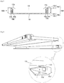
- Fig. 1 is a perspective view of a lighting module according to an embodiment.
- Fig. 2 is an exploded perspective view of the lighting module shown in Fig. 1 .
- Fig. 3 is a cross sectional view of the lighting module shown in Fig. 1 taken along line A-A'.
- a lighting module 100 includes a light guide plate 110, an optical plate 120, a first light source 130a, a second light source 130b, a first case 150A and a second case 150B.
- the first case 150A receives the first light source 130a and covers one side of the light guide plate 110.
- the second case 150B receives the second light source 130b and covers the other side of the light guide plate 110. Since the second case 150B is the same as the first case 150A, a description of the second case 150B is replaced by a description of the first case 150A.
- the first case 150A includes a lower case 150a' and an upper case 150a".
- the lower case 150a' and the upper case 150a" may be coupled to each other by a plurality of screws "S".
- the lower case 150a' includes a base 151a' and an extension part 152a'.
- the first light source 130a is disposed on the inner surface of the base 151a'.
- the extension part 152a' extends from one side edge of the inner surface of the base 151a' in a direction perpendicular to the inner surface.
- the upper case 150a" includes a base 151a" and an extension part 152a".
- the base 151a' of the lower case 150a' is disposed on the inner surface of the base 151a".
- the extension part 152a" extends from one side edge of the inner surface of the base 151a" in a direction perpendicular to the inner surface.
- the length of the extension part 152a" of the upper case 150a" may be different from the length of the extension part 152a' of the lower case 150a'.
- the length of the extension part 152a' of the lower case 150a' may be greater than that of the extension part 152a" of the upper case 150a".
- the base 151a' of the lower case 150a' may include a groove "g1".
- the base 151a" of the upper case 150a” may include a hole “h1".
- the hole “h1” is disposed at a position corresponding to the groove "g1”.
- the base 151a' of the lower case 150a' includes a second opening G2.
- the base 151a" of the upper case 150a" includes a first opening G1.
- the second opening G2 of the lower case 150a' is disposed at a position corresponding to the first opening G1 of the upper case 150a".
- the second opening G2 and the first opening G1 may be disposed on one side of the first light source 130a.
- a driving driver 190 is disposed in the second opening G2 of the lower case 150a' and the first opening G1 of the upper case 150a".
- the driving driver 190 is electrically connected with the first light source 130a and supplies the first light source 130a with electric power from the outside.
- the driving driver 190 controls the on/off of the first light source 130a.
- the extension part 152a' of the lower case 150a' may include a groove into which one side of a substrate 131a of the first light source 130a is inserted.
- the extension part 152a" of the upper case 150a" may include a groove into which the other side of the substrate 131a of the first light source 130a is inserted. Therefore, the first light source 130a can be stably coupled to the first case 150A.
- the extension part 152a' of the lower case 150a' may include a receiving groove "r". This will be described with reference to Fig. 4 .
- Fig. 4 is an exploded perspective view for describing how the first case shown in Fig. 2 is coupled to the light guide plate shown in Fig. 2 .
- a projection 113 formed on one side of the light guide plate 110 is inserted into the receiving groove "r". Due to the coupling of the receiving groove "r" and the projection 113, a coupling force between the extension part 152a' of the lower case 150a' and the light guide plate 110 can be strengthened and the light guide plate 110 can be prevented from moving or separating.
- the projection 113 may be disposed on the other side of the light guide plate 110 and the receiving groove "r" may be disposed in the extension part 152a" of the upper case 150a".
- the projection 113 may be disposed on both sides of the light guide plate 110 and the receiving groove "r” may be disposed in the lower case 150a' and the upper case 150a".
- the base 151a' and the extension part 152a' of the lower case 150a' may be independently formed respectively.
- the lower case 150a' may be also formed by coupling the base 151a' and the extension part 152a'.
- the base 151a" and the extension part 152a" of the upper case 150a" may be also independently formed respectively.
- the upper case 150a" may be also formed by coupling the base 151a" and the extension part 152a".
- the extension part 152a' of the lower case 150a' and the extension part 152a" of the upper case 150a" support both sides of the substrate 131a of the first light source 130a respectively.
- the upper case 150a" may include a receiving portion "R".
- the receiving portion "R” receives one side of the first light source 130a and one side of the base 151a' of the lower case 150a'.
- the first light source 130a is received in the first case 150A.
- the first light source 130a is disposed on the inner surface of the base 151a' of the lower case 150a' of the first case 150A.
- the first light source 130a includes the substrate 131a and a light emitting device 132a.
- a plurality of the light emitting devices 132a are disposed on one surface the substrate 131a.
- the plurality of the light emitting devices 132a may be disposed in a row or in a plurality of rows.
- the other surface of the substrate 131a is disposed on the inner surface of the base 151a' of the lower case 150a' of the first case 150A.
- the one side of the substrate 131a is supported by the extension part 152a' of the lower case 150a' of the first case 150A.
- the other side of the substrate 131a is supported by the extension part 152a" of the upper case 150a"of the first case 150A.
- the other side of the substrate 131a may be disposed in the receiving portion "R" of the upper case 150a"of the first case 150A.
- the substrate 131a may be, for example, a printed circuit board (PCB), a metal core PCB (MCPCB), a flexible PCB (FPCB) and a ceramic substrate.
- PCB printed circuit board
- MCPCB metal core PCB
- FPCB flexible PCB
- a plurality of the light emitting devices 132a may emit lights having the same color or may emit lights having mutually different colors.
- the lighting module according to the embodiment can emit light having various colors. Accordingly, the lighting module according to the embodiment can create emotional lighting.
- the light emitting device 132a may be a blue light emitting device. However, light emitting device 132a may be a white light emitting device having a high color rendering index (CRI), if possible. A synthetic resin including a fluorescent material is molded on a blue light emitting chip, so that the white light emitting device emits white light.
- CRI color rendering index
- the fluorescent material may include at least one of a garnet based fluorescent material (YAG, TAG), a silicate based fluorescent material, a nitride based fluorescent material and an oxynitride based fluorescent material.
- YAG, TAG garnet based fluorescent material
- silicate based fluorescent material e.g., silicate based fluorescent material
- nitride based fluorescent material e.g., silicate based fluorescent material
- an oxynitride based fluorescent material e.g., oxynitride based fluorescent material.
- the light emitting device 132a may be formed to emit natural light (white light) by causing the synthetic resins to include only a yellow fluorescent material
- the light emitting device 132a may further include a green fluorescent material or a red fluorescent material in order to improve the color rendering index and to reduce the color temperature.
- the addition ratio of the colors of the fluorescent materials is based on the fact that it is recommended that the green fluorescent material is more used than the red fluorescent material, and the yellow fluorescent material is more used than the green fluorescent material.
- the yellow fluorescent material may include YAG of the garnet based fluorescent material, a silicate based fluorescent material and an oxynitride based fluorescent material.
- the red fluorescent material may include a silicate based fluorescent material and an oxynitride based fluorescent material.
- the red fluorescent material may include a nitride based fluorescent material.
- the synthetic resin may be mixed with various kinds of the fluorescent materials or may be configured by a layer including the red fluorescent material, a layer including the green fluorescent material and a layer including the yellow fluorescent material, which are formed separately from each other.
- the second light source 130b includes a substrate 131b and a light emitting device 132b. Since the arrangement type of the substrate 131b and the light emitting device 132b of the second light source 130b are the same as the arrangement type of the substrate 131a and the light emitting device 132a of the first light source 130a, detailed description thereof will be omitted.
- the first light source 130a and the second light source 130b are disposed opposite to each other with the light guide plate 110 placed therebetween.
- the first light source 130a is disposed on one side of the light guide plate 110.
- the second light source 130b is disposed on the other side of the light guide plate 110.
- the light emitting device 132a of the first light source 130a and the light emitting device 132b of the second light source 130b may have mutually different color temperatures.
- a plurality of the light emitting devices 132a of the first light source 130a may be warm white LEDs and a plurality of the light emitting devices 132b of the second light source 130b may be cool white LEDs.
- the warm white LED and the cool white LED emit white light. Since the warm white LED and the cool white LED emit correlated color temperatures respectively and can emit mixed white light, a color rendering index (CRI) which represents how close light is to natural sunlight is improved. As a result, it is possible to prevent an actual color of an object from being distorted and to reduce the fatigue of the eyes of users.
- CRI color rendering index
- the light guide plate 110 is disposed between the first light source 130a and the second light source 130b both of which are disposed corresponding to each other. Specifically, one side of the light guide plate 110 is disposed corresponding to the first light source 130a. The other side opposite to the one side of the light guide plate 110 is disposed corresponding to the second light source 130b.
- the light guide plate 110 receives light through the both sides thereof and emits the light through a top surface thereof and a bottom surface thereof. As such, the light guide plate 110 guides light and changes the path of the light.
- the one side of the light guide plate 110 is inserted into the first case 150A.
- the other side of the light guide plate 110 is inserted into the second case 150B.
- the one side and the other side of the light guide plate 110 include a portion of the top and the bottom surfaces of the light guide plate 110.
- the material of the of the light guide plate 110 may be, for example, polyethylene terephthlate (PET), poly carbonate (PC), cycloolefin copolymer (COC) and polyethylene naphthalate (PEN) and an acrylic resin like polymethyl metaacrylate (PMMA) in consideration of thermal expansion depending on a temperature in use of the material.
- PET polyethylene terephthlate
- PC poly carbonate
- COC cycloolefin copolymer
- PEN polyethylene naphthalate
- PMMA polymethyl metaacrylate
- the optical plate 120 is disposed on one side of the light guide plate 110.
- the optical plate 120 may be disposed on the other side of the light guide plate 110.
- the optical plate 120 may be disposed on both sides of the light guide plate 110.
- the optical plate 120 is able to reflect a part of light from the first and the second light sources 130a and 130b and to transmit the rest of the light. Therefore, in the lighting module shown in Fig. 3 , it is possible to cause amounts of the lights which are emitted upward and downward from the lighting module to be different from each other. In the lighting module shown in Fig. 3 , when the optical plate 120 is not provided, about half of the lights from the light sources 130a and 130b is emitted upward from the lighting module, that is, through the top surface of the light guide plate 110 and the rest of the half the lights is emitted downward from the lighting module, that is, through the bottom surface of the light guide plate 110. Contrary to this, due to the optical plate 120 of the lighting module according to the embodiment shown in Fig. 3 , the amount of the light which is emitted upward can be controlled to be more than the amount of the light which is emitted downward.
- the optical plate 120 may have a plate shape capable of both reflecting and transmitting light.
- the optical plate 120 may be adhered to one side of the light guide plate 110.
- the optical plate 120 may be also printed on one side of the light guide plate 110 by using semi-light transmitting ink. This case will be described with reference to Fig. 5 .
- Fig. 5 is a cross sectional view of another embodiment of the lighting module shown in Fig. 3 .
- An optical plate 120' of the lighting module shown in Fig. 5 may be printed on one side of the light guide plate 110 by using the semi-light transmitting ink.
- the optical plate 120' may include a plurality of holes 120'-a. This will be described in detail with reference to Fig. 6 .
- Fig. 6 is a view of the optical plate shown in Fig.5 as viewed from the bottom.
- the optical plate 120' include a plurality of holes 120'-a.
- the plurality of the holes 120'-a pass through both sides of the optical plate 120'.
- the plurality of the holes 120'-a are uniformly distributed in the optical plate 120'.
- the plurality of the holes 120'-a may be arranged in accordance with a predetermined row and column.
- Fig. 7 is a view for describing a light distribution of the lighting module shown in Fig. 3 .
- an upper light distribution of the lighting module shown in Fig. 3 is different from a lower light distribution of the lighting module shown in Fig. 3 .
- the upper light distribution that is, a distribution of light which is emitted on the top surface of the light guide plate 110 is wider than the lower light distribution, that is, a distribution of light which is emitted through the bottom surface of the optical plate 120.
- the upper light distribution and the lower light distribution may show a general Lambertian shape.
- the lighting module shown in Fig. 5 has a light distribution similar to that of the lighting module shown in Fig. 7 .
- the upper light distribution and the lower light distribution of the lighting module shown in Fig. 5 may be changed depending on the diameter of the plurality of the holes 120'-a. The larger the diameter of the hole 120'-a is, the wider the lower light distribution may be. The less diameter of the hole 120'-a is, the smaller the lower light distribution may be.
- the optical plate 120' shown in Fig. 6 may include embodiments in various shapes. This will be described with reference to Figs. 8 to 10 .
- Figs. 8 to 10 show modified examples of the optical plate shown in Fig. 6 .
- An optical plate 120" shown in Fig. 8 like the optical plate 120' shown in Fig. 6 , includes the plurality of the holes 120'-a. However, unlike the optical plate 120' shown in Fig. 6 , the optical plate 120" shown in Fig. 8 includes the plurality of the holes 120'-a which are actually disposed in the central portion of the optical plate 120".
- An optical plate 120'" shown in Fig. 9 like the optical plate 120' shown in Fig. 6 , includes the plurality of the holes 120'-a. However, unlike the optical plate 120' shown in Fig. 6 , the optical plate 120"' shown in Fig. 9 includes the plurality of the holes 120'-a which are actually disposed in the outer portion of the optical plate 120"'.
- An optical plate 120'''' shown in Fig. 10 like the optical plate 120' shown in Fig. 6 , includes the plurality of the holes 120'-a. Moreover, the optical plate 120'''' shown in Fig. 10 includes a plurality of auxiliary holes 120'-b. The diameter of the auxiliary hole 120'-b is less than that of the hole 120'-a. The plurality of the holes 120'-a are actually disposed in the central portion of the optical plate 120"". The plurality of the auxiliary holes 120'-b are actually disposed in the outer portion of the optical plate 120"". The number of the auxiliary holes 120'-b may be greater than that of the holes 120'-a. Besides, the size of the auxiliary holes 120'-b may be smaller than that of the holes 120'-a.
- a light distribution of the lighting module including the optical plate shown in Figs. 8 to 10 will be described with reference to Fig. 7 .
- the upper light distribution and the lower light distribution of the lighting module including the optical plate 120" shown in Fig. 8 may have a bet-wing shape and a spot shape respectively.
- the upper light distribution and the lower light distribution of the lighting module including the optical plate 120"' shown in Fig. 9 may have a Lambertian shape and a bet-wing shape respectively.
- the upper light distribution and the lower light distribution of the lighting module including the optical plate 120"" shown in Fig. 10 may have a shape similar to that of Fig. 7 .
- the lighting module including various shaped upper and lower light distributions
- the light guide plate 110 may include a predetermined pattern. This will be described in detail with reference to Figs. 11 to 12 .
- Fig. 11 is a cross sectional view of further another embodiment of the lighting module shown in Fig. 3 .
- Fig. 12 is a cross sectional view of still another embodiment of the lighting module shown in Fig. 3 .
- the light guide plate 110 may include a predetermined pattern 115 therewithin.
- the predetermined pattern may be disposed within the light guide plate 110, particularly, in a central portion of the light guide plate 110 in a row.
- the predetermined pattern 115 may be formed within the light guide plate 110 by using a laser processing method.
- the predetermined pattern 115 may have a shape with an empty interior.
- the predetermined pattern 115 changes the path of light from the first light source 130a and the second light source 130b and allows the light to be emitted through both surfaces of the light guide plate 110.
- a plurality of the predetermined patterns 115 may be provided.
- the plurality of the patterns 115 may have the same type and may be disposed within the light guide plate 110 in a row. Particularly, the plurality of the patterns 115 may be disposed in an inner central portion of the light guide plate 110 in a row. In this case, the light from the first light source 130a and the second light source 130b may be emitted through the top and the bottom surfaces of the light guide plate 110 at the same ratio.
- the plurality of the patterns 115 may be disposed closer to one of the top and the bottom surfaces of the light guide plate 110.
- an amount of the light which is emitted through the top surface of the light guide plate 110 may be controlled to be different from an amount of the light which is emitted through the bottom surface.
- the cross section of the predetermined pattern 115 may have a circular shape. Moreover, the predetermined pattern 115 may have various shapes. For example, the cross section of the predetermined pattern 115 may have an elliptical shape or a slot shape. The cross section of the predetermined pattern 115 may also have a shape formed through a combination of a circle and an ellipse. That is, the upper portion of the shape may be elliptical and the lower portion of the shape may be circular. It is possible to cause the amounts of the lights which are emitted through the top and the bottom surfaces of the light guide plate 110 to be different from each other through the pattern 115.
- An interval between the predetermined patterns 115 may be regular or may not be regular. Specifically, the density of the pattern 115 may become greater the closer it is to a central portion from both sides of the light guide plate 110. In other words, an interval between the adjacent patterns 115 may become less the closer it is to the central portion of the light guide plate 110.
- a lighting module having such a pattern 115 is able to obtain various light distributions.
- the light guide plate 110 may have a predetermined pattern 115'.
- the predetermined pattern 115' may be disposed on one of the top surface and the bottom surface of the light guide plate 110.
- the predetermined pattern 115' may have a hemispherical cross section. Moreover, the predetermined pattern 115' may have various shaped cross sections. For example, the cross section of the predetermined pattern 115' may have a semi-elliptical shape or a half slot shape.
- An interval between the predetermined patterns 115' may be regular or may not be regular. Specifically, the density of the pattern 115' may become greater the closer it is to a central portion from both sides of the light guide plate 110. In other words, an interval between the adjacent patterns 115' may become less the closer it is to the central portion of the light guide plate 110.
- a lighting module having such a pattern 115' is able to obtain various light distributions.
- the lighting module according to the embodiment may further include a first phosphor luminescent film 170a and a second phosphor luminescent film 170b.
- the first phosphor luminescent film 170a is disposed between the light guide plate 110 and the first light source 130a.
- the second phosphor luminescent film 170b is disposed between the light guide plate 110 and the second light source 130b.
- the first and the second phosphor luminescent films 170a and 170b may emit light with a wavelength different from that of the light emitted from the first and the second light sources 130a and 130b.
- the first and the second phosphor luminescent films 170a and 170b may include a transparent resin and a fluorescent material contained within the transparent resin.
- the fluorescent material of the first phosphor luminescent film 170a may be the same as or different from the fluorescent material of the second phosphor luminescent film 170b.
- the fluorescent material is excited by the light from the first and the second light sources 130a and 130b and is able to emit light with a wavelength different from that of the light from the first and the second light sources 130a and 130b.
- the fluorescent material may be at least one of a yellow fluorescent material, a red fluorescent material and a green fluorescent material.
- a curing agent or an additive may be included within the transparent resins of the first and the second phosphor luminescent films 170a and 170b.
- the curing agent cures the transparent resin.
- the additive uniformly disperses the fluorescent material within the transparent resin.
- the transparent resin may include a diffusion material. The diffusion material is able to improve an excitation ratio of the fluorescent material by improving the refraction of light.
- the lighting module according to the embodiment may further include a diffuser plate.
- the diffuser plate diffuses light which is emitted from the light guide plate 110. Through use of the diffuser plate, light spot can be removed.
- the diffuser plate is disposed on at least one of the top and the bottom surfaces of the light guide plate 110. Both sides of the diffuser plate may be inserted into the first case 150A and the second case 150B respectively.
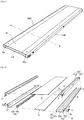
- Fig. 13 is a perspective view of a lighting module according to an embodiment.
- Fig. 14 is an exploded perspective view of the lighting module shown in Fig. 13 .
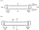
- Fig. 15 is a cross sectional view of the lighting module shown in Fig. 13 taken along line B-B'.
- the lighting module includes a first optical plate 121, a second optical plate 123, a first light source 130a, a second light source 130b, a first case 150A and a second case 150B.
- the lighting module shown in Figs. 13 to 15 does not include the light guide plate 110 of the lighting module shown in Figs. 1 to 3 .
- the lighting module shown in Figs. 13 to 15 includes the first and the second optical plates 121 and 123.
- the first and the second optical plates 121 and 123 reflect a part of light from the first and the second light sources 130a and 130b and transmit the rest of the light.
- the first and the second optical plates 121 and 123 may be plates having a predetermined reflectance and transmittance.
- the reflectance and the transmittance of the first and the second optical plates 121 and 123 may be equal or not equal to each other.
- the reflectance and the transmittance of the first and the second optical plates 121 and 123 are equal to each other, the amount of light which is emitted downward from the first optical plate 121 is almost the same as the amount of light which is emitted upward from the second optical plate 123.
- the amount of light which is emitted downward from the first optical plate 121 is different from the amount of light which is emitted upward from the second optical plate 123.
- the first and the second optical plates 121 and 123 may be connected to the first and the second cases 150A and 150B. Specifically, one side of the first optical plate 121 may be connected to an extension part 152a' of the lower case 150a' of the first case 150A.
- the other side of the first optical plate 121 may be connected to an extension part of the lower case of the second case 150B.
- One side of the second optical plate 123 may be connected to an extension part 152a" of the upper case 150a"of the first case 150A.
- the other side of the second optical plate 123 may be connected to an extension part of the upper case 150a"of the second case 150B.
- the first and the second optical plates 121and 123 are disposed separately from and opposite to each other.
- the first and the second optical plates 121and 123 may have holes.
- the light from the first and the second light sources 130a and 130b is emitted outward through the holes. This will be described in detail with reference to Fig. 16 .
- Fig. 16 is a cross sectional view of another embodiment of the lighting module shown in Fig. 15 .
- the first optical plate 121 includes a plurality of holes 121-a and the second optical plate 123 includes a plurality of holes 123-a.
- Light passes through the holes 121-a and 123-a of the first and the second optical plates 121 and 123.
- the inner surfaces of the first and the second optical plates 121 and 123 reflect the light.
- the shape or the size of the hole 121-a of the first optical plate 121 may be the same as or different from the shape and the size of the hole 123-a of the second optical plate 123.
- an amount of light which is emitted downward from the first optical plate 121 is almost the same as an amount of light which is emitted upward from the second optical plate 123. Contrary to this, as shown in Fig.
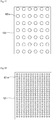
- Fig. 17 is a front view of the second optical plate shown in Fig. 16 as viewed from the top.
- Fig. 18 is a front view of the first optical plate shown in Fig. 16 as viewed from the bottom.
- the hole 121-a of the first optical plate 121 may pass through the first optical plate 121.
- a plurality of the holes 121-a are provided and may be uniformly distributed.
- the hole 123-a of the second optical plate 123 may pass through the second optical plate 123.
- a plurality of the holes 123-a are provided and may be uniformly distributed.
- the size of the hole 121-a of the first optical plate 121 is smaller than the size of the hole 123-a of the second optical plate 123.
- an amount of light which is emitted through the hole 121-a of the first optical plate 121 may be different from an amount of light which is emitted through the hole 123-a of the second optical plate 123.
- the first and the second optical plates 121 and 123 include a plurality of the holes 121-a and a plurality of the holes 123-a respectively.
- a disposition density of the holes 121-a of the first optical plate 121 may be different from a disposition density of the holes 123-a of the second optical plate 123.
- the hole 121-a of the first optical plate 121 and the hole 123-a of the second optical plate 123 have a circular shape.
- the hole 121-a of the first optical plate 121 and the hole 123-a of the second optical plate 123 may have various shapes such as an elliptical shape, a polygonal shape or a slot shape.
- the hole 121-a of the first optical plate 121 and the hole 123-a of the second optical plate 123 may be disposed only on one of the first optical plate 121 or the second optical plate 123.
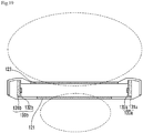
- Fig. 19 is a view showing a light distribution of the lighting module shown in Fig. 15 .
- the light distribution shown in Fig. 19 may be obtained when a ratio of a reflectance to a transmittance of the first optical plate 121 is different from a ratio of a reflectance to a transmittance of the second optical plate 123.
- the light distribution shown in Fig. 19 may be obtained when the reflectance of the first optical plate 121 is greater than that of the second optical plate 123 or when the transmittance of the first optical plate 121 is less than that of the second optical plate 123.
- the upper light distribution of the lighting module shown in Fig. 15 is different from the lower light distribution of the lighting module shown in Fig. 15 .
- an amount of light which is emitted through the second optical plate 123 is more than an amount of light which is emitted through the first optical plate 121 and it can also be seen that a distribution of light which is emitted through the second optical plate 123 is wider than a distribution of light which is emitted through the first optical plate 121.
- the lighting module shown in Fig. 16 also has a light distribution similar to the light distribution shown in Fig. 19 .
- the first and the second optical plates 121 and 123 of the lighting module according to the embodiment may emit excited light caused by light incident thereon.
- the first and the second optical plates 121 and 123 are able to emit excited light having a wavelength different from that of light emitted from the first and the second light sources 130a and 130b. Due to the light from the first and the second light sources 130a and 130b and the excited light, the lighting module according to the embodiment is able to emit light having various color senses.
- the first and the second optical plates 121 and 123 may include a transparent resin and a fluorescent material contained within the transparent resin.
- the fluorescent material of the first optical plate 121 may be the same as or different from the fluorescent material of the second optical plate 123.
- a curing agent or an additive may be included within the transparent resins of the first and the second optical plates 121 and 123.
- the curing agent cures the transparent resin.
- the additive uniformly disperses the fluorescent material within the transparent resin.
- the transparent resin may include a diffusion agent. The diffusion agent is able to improve an excitation ratio of the fluorescent material by improving the refraction of light.
- the first and the second optical plates 121 and 123 may include a diffusing material diffusing light which is incident.
- the first and the second optical plates 121 and 123 include the diffusing material, spots of the first and the second light sources 130a and 130b can be removed.
- a diffusion function may be included in at least one of the first and the second optical plates 121 and 123.
- Table 1 shows a practical specification of the lighting modules according to the embodiment shown in Figs. 1 and 13 .
- Table 1 Product Item Value Strip Spec. (13S * 5P) Voltage(V) 39 Current(mA) 350 Power(W) 13.65 Module Spec. Total Lumen output(lm) Up Lumen Output 2,500 500 Down Lumen Output 2,000 Module Power(W) 27.3 Efficacy(lm/W) 90 CCT(K) 4,000 CRI 80 Fixture Spec. Lumen Output(lm) 10,000(Up-Down: 2,000-8,000) DC Power Consumption(W) 110
- an up lumen output is less than a down lumen output. Contrary to this, the up lumen output may be greater than the down lumen output. For example, a ratio of the down lumen output to the up lumen output maybe from 4:6 to 2:8.
- a value of width W (mm) ⁇ height H (mm) ⁇ length L (mm) of the lighting modules shown in Figs. 1 and 13 may be either 80 ⁇ 12 ⁇ 560 or 45 ⁇ 12 ⁇ 560.
- any reference in this specification to "one embodiment,” “an embodiment,” “example embodiment,” etc. means that a particular feature, structure, or characteristic described in connection with the embodiment is included in at least one embodiment of the invention.
- the appearances of such phrases in various places in the specification are not necessarily all referring to the same embodiment.
Landscapes
- Physics & Mathematics (AREA)
- General Physics & Mathematics (AREA)
- Optics & Photonics (AREA)
- Engineering & Computer Science (AREA)
- General Engineering & Computer Science (AREA)
- Planar Illumination Modules (AREA)
- Non-Portable Lighting Devices Or Systems Thereof (AREA)
Abstract
Description
- Embodiments may relate to a lighting module.
- A light emitting diode (LED) is an energy device for converting electric energy into light energy. Compared with an electric bulb, the LED has higher conversion efficiency, lower power consumption and a longer life span. As there advantages are widely known, more and more attentions are now paid to a lighting apparatus using the LED.
- The lighting apparatus using the LED are generally classified into a direct lighting apparatus and an indirect lighting apparatus. The direct lighting apparatus emits light emitted from the LED without changing the path of the light. The indirect lighting apparatus emits light emitted from the LED by changing the path of the light through reflecting means and so on. Compared with the direct lighting apparatus, the indirect lighting apparatus mitigates to some degree the intensified light emitted from the LED and protects the eyes of users.
- One embodiment is a lighting module. The lighting module includes: a first and a second light sources, both of which are disposed opposite to each other; a first case including the first light source; a second case including the second light source; and an optical plate of which one side is connected to the first case and the other side is connected to the second case and on which light from the first and the second light sources is incident.
- The optical plate comprises a first optical plate and a second optical plate and wherein the first and the second optical plates are disposed opposite to each other.
- A reflectance of the first optical plate is different from a reflectance of the second optical plate.
- A transmittance of the first optical plate is different from a transmittance of the second optical plate.
- At least one of the first and/or the second optical plates comprises a hole.
- The first optical plate and the second optical plate comprise the hole and wherein the hole of the first optical plate is different from the hole of the second optical plate.
- The first optical plate and the second optical plate comprise a plurality of the holes and wherein a density of the holes of the first optical plate is different from a density of the holes of the second optical plate.
- At least one of the first and/or the second optical plates emits light with a wavelength different from that of the light from the first and the second light sources.
- At least one of the first and/or the second optical plates comprises a diffusing material diffusing light from the first and the second light sources.
- The optical plate comprises a plurality of holes, and the plurality of the holes are disposed in at least one of a central portion and/or an outer portion of the optical plate.
- The optical plate comprises a plurality of holes and a plurality of auxiliary holes which are smaller than the holes, and wherein the plurality of the holes are disposed in a central portion of the optical plate and the plurality of the auxiliary holes are disposed in an outer portion of the optical plate.
- The lighting module further comprises a light guide plate disposed between the first light source and the second light source, and wherein the optical plate is disposed on at least one of a top surface and/or a bottom surface of the light guide plate.
- The optical plate is printed on the light guide plate.
- The light guide plate comprises a predetermined pattern.
- The pattern is disposed within the light guide plate on at least one of the top surface and/or the bottom surface of the light guide plate.
- The pattern is disposed closer to at least one of the top and/or the bottom surfaces of the light guide plate.
- The pattern comprises at least one of a circular shape, an elliptical shape and/or a slot shape.
- A density of the pattern becomes greater the closer it is to a central portion from both sides of the light guide plate.
- The lighting module further comprises a diffuser plate disposed on at least one of the top surface and/or the bottom surface of the light guide plate.
- Another embodiment is a lighting module. The lighting module includes: a light source which includes a substrate and a light emitting device disposed on the substrate; a case which includes a base on which the substrate of the light source is disposed and a first and a second extension parts, each of which supports one side and the other side of the substrate respectively; a first plate which is connected to the first extension part of the case and reflects and transmits light from the light emitting device of the light source; and a second plate which is connected to the second extension part of the case and reflects and transmits light from the light emitting device of the light source.
- Arrangements and embodiments may be described in detail with reference to the following drawings in which like reference numerals refer to like elements and wherein:
-
Fig. 1 is a perspective view of a lighting module according to an embodiment; -
Fig. 2 is an exploded perspective view of the lighting module shown inFig. 1 ; -
Fig. 3 is a cross sectional view of the lighting module shown inFig. 1 taken along line A-A'; -
Fig. 4 is an exploded perspective view for describing how the first case shown inFig. 2 is coupled to the light guide plate shown inFig. 2 ; -
Fig. 5 is a cross sectional view of another embodiment of the lighting module shown inFig. 3 ; -
Fig. 6 is a view of the optical plate shown inFig.5 as viewed from the bottom. -
Fig. 7 is a view for describing a light distribution of the lighting module shown inFig. 3 ; -
Figs. 8 to 10 show modified examples of the optical plate shown inFig. 6 ; -
Fig. 11 is a cross sectional view of further another embodiment of the lighting module shown inFig. 3 ; -
Fig. 12 is a cross sectional view of still another embodiment of the lighting module shown inFig. 3 ; -
Fig. 13 is a perspective view of a lighting module according to an embodiment; -
Fig. 14 is an exploded perspective view of the lighting module shown inFig. 13 ; -
Fig. 15 is a cross sectional view of the lighting module shown inFig. 13 taken along line B-B'; -
Fig. 16 is a cross sectional view of another embodiment of the lighting module shown inFig. 15 ; -
Fig. 17 is a front view of a second optical plate shown inFig. 16 as viewed from the top; -
Fig. 18 is a front view of a first optical plate shown inFig. 16 as viewed from the bottom; -
Fig. 19 is a view showing a light distribution of the lighting module shown inFig. 15 . - A thickness or a size of each layer may be magnified, omitted or schematically shown for the purpose of convenience and clearness of description. The size of each component may not necessarily mean its actual size.
- It should be understood that when an element is referred to as being 'on' or "under" another element, it may be directly on/under the element, and/or one or more intervening elements may also be present. When an element is referred to as being `on' or 'under', 'under the element' as well as 'on the element' may be included based on the element.
- An embodiment may be described in detail with reference to the accompanying drawings.
-
Fig. 1 is a perspective view of a lighting module according to an embodiment.Fig. 2 is an exploded perspective view of the lighting module shown inFig. 1 .Fig. 3 is a cross sectional view of the lighting module shown inFig. 1 taken along line A-A'. - Referring to
Figs. 1 and3 , a lighting module 100 includes alight guide plate 110, anoptical plate 120, afirst light source 130a, asecond light source 130b, afirst case 150A and asecond case 150B. - The
first case 150A receives thefirst light source 130a and covers one side of thelight guide plate 110. Thesecond case 150B receives the secondlight source 130b and covers the other side of thelight guide plate 110. Since thesecond case 150B is the same as thefirst case 150A, a description of thesecond case 150B is replaced by a description of thefirst case 150A. - The
first case 150A includes alower case 150a' and anupper case 150a". Thelower case 150a' and theupper case 150a" may be coupled to each other by a plurality of screws "S". - The
lower case 150a' includes abase 151a' and anextension part 152a'. Thefirst light source 130a is disposed on the inner surface of thebase 151a'. Theextension part 152a' extends from one side edge of the inner surface of thebase 151a' in a direction perpendicular to the inner surface. - The
upper case 150a" includes abase 151a" and anextension part 152a". Thebase 151a' of thelower case 150a' is disposed on the inner surface of thebase 151a". Theextension part 152a" extends from one side edge of the inner surface of thebase 151a" in a direction perpendicular to the inner surface. - Here, the length of the
extension part 152a" of theupper case 150a" may be different from the length of theextension part 152a' of thelower case 150a'. For example, the length of theextension part 152a' of thelower case 150a' may be greater than that of theextension part 152a" of theupper case 150a". - The
base 151a' of thelower case 150a' may include a groove "g1". Thebase 151a" of theupper case 150a" may include a hole "h1". The hole "h1" is disposed at a position corresponding to the groove "g1". When thelower case 150a' is coupled to theupper case 150a", the screw "S" passes through the hole "h1" and is inserted into the groove "g1". As a result, thebase 151a' of thelower case 150a' is coupled close to thebase 151a" of theupper case 150a". Thebase 151a' of thelower case 150a' includes the groove "g1" instead of the hole in order that thefirst light source 130a is prevented from being damaged or broken by the screw "S" and from being electrically contacted with the screw "S". - The
base 151a' of thelower case 150a' includes a second opening G2. Thebase 151a" of theupper case 150a" includes a first opening G1. The second opening G2 of thelower case 150a' is disposed at a position corresponding to the first opening G1 of theupper case 150a". Specifically, the second opening G2 and the first opening G1 may be disposed on one side of thefirst light source 130a. A drivingdriver 190 is disposed in the second opening G2 of thelower case 150a' and the first opening G1 of theupper case 150a". The drivingdriver 190 is electrically connected with thefirst light source 130a and supplies thefirst light source 130a with electric power from the outside. The drivingdriver 190 controls the on/off of thefirst light source 130a. - Though not shown in the drawings, the
extension part 152a' of thelower case 150a' may include a groove into which one side of asubstrate 131a of thefirst light source 130a is inserted. Theextension part 152a" of theupper case 150a" may include a groove into which the other side of thesubstrate 131a of thefirst light source 130a is inserted. Therefore, thefirst light source 130a can be stably coupled to thefirst case 150A. - The
extension part 152a' of thelower case 150a' may include a receiving groove "r". This will be described with reference toFig. 4 . -
Fig. 4 is an exploded perspective view for describing how the first case shown inFig. 2 is coupled to the light guide plate shown inFig. 2 . - Referring to
Fig. 4 , aprojection 113 formed on one side of thelight guide plate 110 is inserted into the receiving groove "r". Due to the coupling of the receiving groove "r" and theprojection 113, a coupling force between theextension part 152a' of thelower case 150a' and thelight guide plate 110 can be strengthened and thelight guide plate 110 can be prevented from moving or separating. Here, theprojection 113 may be disposed on the other side of thelight guide plate 110 and the receiving groove "r" may be disposed in theextension part 152a" of theupper case 150a". Theprojection 113 may be disposed on both sides of thelight guide plate 110 and the receiving groove "r" may be disposed in thelower case 150a' and theupper case 150a". - Referring back to
Figs. 1 to 3 , thebase 151a' and theextension part 152a' of thelower case 150a' may be independently formed respectively. Thelower case 150a' may be also formed by coupling thebase 151a' and theextension part 152a'. Thebase 151a" and theextension part 152a" of theupper case 150a" may be also independently formed respectively. Theupper case 150a" may be also formed by coupling thebase 151a" and theextension part 152a". - When the
first light source 130a is disposed on the inner surface of thebase 151a" of theupper case 150a", theextension part 152a' of thelower case 150a' and theextension part 152a" of theupper case 150a" support both sides of thesubstrate 131a of thefirst light source 130a respectively. - The
upper case 150a" may include a receiving portion "R". The receiving portion "R" receives one side of thefirst light source 130a and one side of thebase 151a' of thelower case 150a'. - The
first light source 130a is received in thefirst case 150A. Thefirst light source 130a is disposed on the inner surface of thebase 151a' of thelower case 150a' of thefirst case 150A. - The
first light source 130a includes thesubstrate 131a and alight emitting device 132a. - A plurality of the
light emitting devices 132a are disposed on one surface thesubstrate 131a. Here, the plurality of thelight emitting devices 132a may be disposed in a row or in a plurality of rows. - The other surface of the
substrate 131a is disposed on the inner surface of thebase 151a' of thelower case 150a' of thefirst case 150A. - The one side of the
substrate 131a is supported by theextension part 152a' of thelower case 150a' of thefirst case 150A. The other side of thesubstrate 131a is supported by theextension part 152a" of theupper case 150a"of thefirst case 150A. Here, the other side of thesubstrate 131a may be disposed in the receiving portion "R" of theupper case 150a"of thefirst case 150A. - The
substrate 131a may be, for example, a printed circuit board (PCB), a metal core PCB (MCPCB), a flexible PCB (FPCB) and a ceramic substrate. - A plurality of the
light emitting devices 132a may emit lights having the same color or may emit lights having mutually different colors. When the plurality of thelight emitting devices 132a emit lights the mutually different colors, the lighting module according to the embodiment can emit light having various colors. Accordingly, the lighting module according to the embodiment can create emotional lighting. - The
light emitting device 132a may be a blue light emitting device. However, light emittingdevice 132a may be a white light emitting device having a high color rendering index (CRI), if possible. A synthetic resin including a fluorescent material is molded on a blue light emitting chip, so that the white light emitting device emits white light. - Here, the fluorescent material may include at least one of a garnet based fluorescent material (YAG, TAG), a silicate based fluorescent material, a nitride based fluorescent material and an oxynitride based fluorescent material. While the
light emitting device 132a may be formed to emit natural light (white light) by causing the synthetic resins to include only a yellow fluorescent material, thelight emitting device 132a may further include a green fluorescent material or a red fluorescent material in order to improve the color rendering index and to reduce the color temperature. When various kinds of the fluorescent materials are mixed in the synthetic resin, the addition ratio of the colors of the fluorescent materials is based on the fact that it is recommended that the green fluorescent material is more used than the red fluorescent material, and the yellow fluorescent material is more used than the green fluorescent material. The yellow fluorescent material may include YAG of the garnet based fluorescent material, a silicate based fluorescent material and an oxynitride based fluorescent material. The red fluorescent material may include a silicate based fluorescent material and an oxynitride based fluorescent material. The red fluorescent material may include a nitride based fluorescent material. The synthetic resin may be mixed with various kinds of the fluorescent materials or may be configured by a layer including the red fluorescent material, a layer including the green fluorescent material and a layer including the yellow fluorescent material, which are formed separately from each other. - The second
light source 130b includes asubstrate 131b and alight emitting device 132b. Since the arrangement type of thesubstrate 131b and thelight emitting device 132b of the secondlight source 130b are the same as the arrangement type of thesubstrate 131a and thelight emitting device 132a of thefirst light source 130a, detailed description thereof will be omitted. - The
first light source 130a and the secondlight source 130b are disposed opposite to each other with thelight guide plate 110 placed therebetween. Thefirst light source 130a is disposed on one side of thelight guide plate 110. The secondlight source 130b is disposed on the other side of thelight guide plate 110. - The
light emitting device 132a of thefirst light source 130a and thelight emitting device 132b of the secondlight source 130b may have mutually different color temperatures. For example, a plurality of thelight emitting devices 132a of thefirst light source 130a may be warm white LEDs and a plurality of thelight emitting devices 132b of the secondlight source 130b may be cool white LEDs. The warm white LED and the cool white LED emit white light. Since the warm white LED and the cool white LED emit correlated color temperatures respectively and can emit mixed white light, a color rendering index (CRI) which represents how close light is to natural sunlight is improved. As a result, it is possible to prevent an actual color of an object from being distorted and to reduce the fatigue of the eyes of users. - The
light guide plate 110 is disposed between thefirst light source 130a and the secondlight source 130b both of which are disposed corresponding to each other. Specifically, one side of thelight guide plate 110 is disposed corresponding to thefirst light source 130a. The other side opposite to the one side of thelight guide plate 110 is disposed corresponding to the secondlight source 130b. - The
light guide plate 110 receives light through the both sides thereof and emits the light through a top surface thereof and a bottom surface thereof. As such, thelight guide plate 110 guides light and changes the path of the light. - The one side of the
light guide plate 110 is inserted into thefirst case 150A. The other side of thelight guide plate 110 is inserted into thesecond case 150B. The one side and the other side of thelight guide plate 110 include a portion of the top and the bottom surfaces of thelight guide plate 110. - In the top and the bottom surfaces of the
light guide plate 110, light is emitted from remaining portions other than portions inserted into the first and thesecond cases - The material of the of the
light guide plate 110 may be, for example, polyethylene terephthlate (PET), poly carbonate (PC), cycloolefin copolymer (COC) and polyethylene naphthalate (PEN) and an acrylic resin like polymethyl metaacrylate (PMMA) in consideration of thermal expansion depending on a temperature in use of the material. - The
optical plate 120 is disposed on one side of thelight guide plate 110. Here, theoptical plate 120 may be disposed on the other side of thelight guide plate 110. Also, theoptical plate 120 may be disposed on both sides of thelight guide plate 110. - The
optical plate 120 is able to reflect a part of light from the first and thesecond light sources Fig. 3 , it is possible to cause amounts of the lights which are emitted upward and downward from the lighting module to be different from each other. In the lighting module shown inFig. 3 , when theoptical plate 120 is not provided, about half of the lights from thelight sources light guide plate 110 and the rest of the half the lights is emitted downward from the lighting module, that is, through the bottom surface of thelight guide plate 110. Contrary to this, due to theoptical plate 120 of the lighting module according to the embodiment shown inFig. 3 , the amount of the light which is emitted upward can be controlled to be more than the amount of the light which is emitted downward. - The
optical plate 120 may have a plate shape capable of both reflecting and transmitting light. - The
optical plate 120 may be adhered to one side of thelight guide plate 110. Theoptical plate 120 may be also printed on one side of thelight guide plate 110 by using semi-light transmitting ink. This case will be described with reference toFig. 5 . -
Fig. 5 is a cross sectional view of another embodiment of the lighting module shown inFig. 3 . - An optical plate 120' of the lighting module shown in
Fig. 5 may be printed on one side of thelight guide plate 110 by using the semi-light transmitting ink. - The optical plate 120' may include a plurality of holes 120'-a. This will be described in detail with reference to
Fig. 6 . -
Fig. 6 is a view of the optical plate shown inFig.5 as viewed from the bottom. - Referring to
Figs. 5 and 6 , the optical plate 120' include a plurality of holes 120'-a. - The plurality of the holes 120'-a pass through both sides of the optical plate 120'. The plurality of the holes 120'-a are uniformly distributed in the optical plate 120'. For example, the plurality of the holes 120'-a may be arranged in accordance with a predetermined row and column.
- Referring to
Fig. 5 , in lights from thefirst light source 130a an the secondlight source 130b, light which is incident on the optical plate 120' is reflected upward, that is, in a direction of the top surface of thelight guide plate 110, and light which is incident on the plurality of the holes 120'-a is emitted outward through the plurality of the holes 120'-a. Amounts of the lights which are emitted upward and downward from the lighting module including the optical plate 120' may be different from each other. -
Fig. 7 is a view for describing a light distribution of the lighting module shown inFig. 3 . - As shown in
Fig. 7 , an upper light distribution of the lighting module shown inFig. 3 is different from a lower light distribution of the lighting module shown inFig. 3 . Specifically, the upper light distribution, that is, a distribution of light which is emitted on the top surface of thelight guide plate 110 is wider than the lower light distribution, that is, a distribution of light which is emitted through the bottom surface of theoptical plate 120. Here, the upper light distribution and the lower light distribution may show a general Lambertian shape. - It can be expected that the lighting module shown in
Fig. 5 has a light distribution similar to that of the lighting module shown inFig. 7 . Here, the upper light distribution and the lower light distribution of the lighting module shown inFig. 5 may be changed depending on the diameter of the plurality of the holes 120'-a. The larger the diameter of the hole 120'-a is, the wider the lower light distribution may be. The less diameter of the hole 120'-a is, the smaller the lower light distribution may be. - The optical plate 120' shown in
Fig. 6 may include embodiments in various shapes. This will be described with reference toFigs. 8 to 10 . -
Figs. 8 to 10 show modified examples of the optical plate shown inFig. 6 . - An
optical plate 120" shown inFig. 8 , like the optical plate 120' shown inFig. 6 , includes the plurality of the holes 120'-a. However, unlike the optical plate 120' shown inFig. 6 , theoptical plate 120" shown inFig. 8 includes the plurality of the holes 120'-a which are actually disposed in the central portion of theoptical plate 120". - An optical plate 120'" shown in
Fig. 9 , like the optical plate 120' shown inFig. 6 , includes the plurality of the holes 120'-a. However, unlike the optical plate 120' shown inFig. 6 , theoptical plate 120"' shown inFig. 9 includes the plurality of the holes 120'-a which are actually disposed in the outer portion of theoptical plate 120"'. - An optical plate 120'''' shown in
Fig. 10 , like the optical plate 120' shown inFig. 6 , includes the plurality of the holes 120'-a. Moreover, the optical plate 120'''' shown inFig. 10 includes a plurality of auxiliary holes 120'-b. The diameter of the auxiliary hole 120'-b is less than that of the hole 120'-a. The plurality of the holes 120'-a are actually disposed in the central portion of theoptical plate 120"". The plurality of the auxiliary holes 120'-b are actually disposed in the outer portion of theoptical plate 120"". The number of the auxiliary holes 120'-b may be greater than that of the holes 120'-a. Besides, the size of the auxiliary holes 120'-b may be smaller than that of the holes 120'-a. - A light distribution of the lighting module including the optical plate shown in
Figs. 8 to 10 will be described with reference toFig. 7 . - The upper light distribution and the lower light distribution of the lighting module including the
optical plate 120" shown inFig. 8 may have a bet-wing shape and a spot shape respectively. - The upper light distribution and the lower light distribution of the lighting module including the
optical plate 120"' shown inFig. 9 may have a Lambertian shape and a bet-wing shape respectively. - The upper light distribution and the lower light distribution of the lighting module including the
optical plate 120"" shown inFig. 10 may have a shape similar to that ofFig. 7 . - As such, through various embodiments of the optical plate, those skilled in the art are able to implement the lighting module including various shaped upper and lower light distributions
- Referring back to
Figs. 1 to 3 , thelight guide plate 110 may include a predetermined pattern. This will be described in detail with reference toFigs. 11 to 12 . -
Fig. 11 is a cross sectional view of further another embodiment of the lighting module shown inFig. 3 .Fig. 12 is a cross sectional view of still another embodiment of the lighting module shown inFig. 3 . - Referring to
Fig. 11 , thelight guide plate 110 may include apredetermined pattern 115 therewithin. The predetermined pattern may be disposed within thelight guide plate 110, particularly, in a central portion of thelight guide plate 110 in a row. - The
predetermined pattern 115 may be formed within thelight guide plate 110 by using a laser processing method. Thepredetermined pattern 115 may have a shape with an empty interior. - The
predetermined pattern 115 changes the path of light from thefirst light source 130a and the secondlight source 130b and allows the light to be emitted through both surfaces of thelight guide plate 110. - A plurality of the
predetermined patterns 115 may be provided. - The plurality of the
patterns 115 may have the same type and may be disposed within thelight guide plate 110 in a row. Particularly, the plurality of thepatterns 115 may be disposed in an inner central portion of thelight guide plate 110 in a row. In this case, the light from thefirst light source 130a and the secondlight source 130b may be emitted through the top and the bottom surfaces of thelight guide plate 110 at the same ratio. - The plurality of the
patterns 115 may be disposed closer to one of the top and the bottom surfaces of thelight guide plate 110. When the plurality of thepatterns 115 are disposed closer to one of the top and the bottom surfaces, an amount of the light which is emitted through the top surface of thelight guide plate 110 may be controlled to be different from an amount of the light which is emitted through the bottom surface. - The cross section of the
predetermined pattern 115 may have a circular shape. Moreover, thepredetermined pattern 115 may have various shapes. For example, the cross section of thepredetermined pattern 115 may have an elliptical shape or a slot shape. The cross section of thepredetermined pattern 115 may also have a shape formed through a combination of a circle and an ellipse. That is, the upper portion of the shape may be elliptical and the lower portion of the shape may be circular. It is possible to cause the amounts of the lights which are emitted through the top and the bottom surfaces of thelight guide plate 110 to be different from each other through thepattern 115. - An interval between the
predetermined patterns 115 may be regular or may not be regular. Specifically, the density of thepattern 115 may become greater the closer it is to a central portion from both sides of thelight guide plate 110. In other words, an interval between theadjacent patterns 115 may become less the closer it is to the central portion of thelight guide plate 110. A lighting module having such apattern 115 is able to obtain various light distributions. - Referring to
Fig. 12 , thelight guide plate 110 may have a predetermined pattern 115'. The predetermined pattern 115' may be disposed on one of the top surface and the bottom surface of thelight guide plate 110. - The predetermined pattern 115' may have a hemispherical cross section. Moreover, the predetermined pattern 115' may have various shaped cross sections. For example, the cross section of the predetermined pattern 115' may have a semi-elliptical shape or a half slot shape.
- An interval between the predetermined patterns 115' may be regular or may not be regular. Specifically, the density of the pattern 115' may become greater the closer it is to a central portion from both sides of the
light guide plate 110. In other words, an interval between the adjacent patterns 115' may become less the closer it is to the central portion of thelight guide plate 110. A lighting module having such a pattern 115' is able to obtain various light distributions. - Referring back to
Figs. 1 to 3 , the lighting module according to the embodiment may further include a firstphosphor luminescent film 170a and a secondphosphor luminescent film 170b. - The first
phosphor luminescent film 170a is disposed between thelight guide plate 110 and thefirst light source 130a. The secondphosphor luminescent film 170b is disposed between thelight guide plate 110 and the secondlight source 130b. - The first and the second
phosphor luminescent films second light sources - The first and the second
phosphor luminescent films phosphor luminescent film 170a may be the same as or different from the fluorescent material of the secondphosphor luminescent film 170b. The fluorescent material is excited by the light from the first and thesecond light sources second light sources - A curing agent or an additive may be included within the transparent resins of the first and the second
phosphor luminescent films - Though not shown in the drawings, the lighting module according to the embodiment may further include a diffuser plate. The diffuser plate diffuses light which is emitted from the
light guide plate 110. Through use of the diffuser plate, light spot can be removed. In this case, the diffuser plate is disposed on at least one of the top and the bottom surfaces of thelight guide plate 110. Both sides of the diffuser plate may be inserted into thefirst case 150A and thesecond case 150B respectively. -
Fig. 13 is a perspective view of a lighting module according to an embodiment.Fig. 14 is an exploded perspective view of the lighting module shown inFig. 13 .Fig. 15 is a cross sectional view of the lighting module shown inFig. 13 taken along line B-B'. - In description of elements of the lighting modules shown in
Figs. 13 to 15 , the same reference numerals as those of the lighting modules shown inFigs. 1 to 3 are assigned to the same elements as those of the lighting modules shown inFigs. 1 to 3 . - Referring to
Figs. 13 to 15 , the lighting module according to the embodiment includes a firstoptical plate 121, a secondoptical plate 123, afirst light source 130a, a secondlight source 130b, afirst case 150A and asecond case 150B. - The lighting module shown in
Figs. 13 to 15 does not include thelight guide plate 110 of the lighting module shown inFigs. 1 to 3 . The lighting module shown inFigs. 13 to 15 includes the first and the secondoptical plates - Description of the
first light source 130a, the secondlight source 130b, thefirst case 150A and thesecond case 150B of the lighting module shown inFigs. 13 to 15 are replaced by the description ofFigs. 1 to 3 . Hereafter, the lighting module shown inFigs. 13 to 15 will be described focusing on the first and the secondoptical plates - The first and the second
optical plates second light sources - The first and the second
optical plates optical plates optical plates optical plate 121 is almost the same as the amount of light which is emitted upward from the secondoptical plate 123. When the reflectance and the transmittance of the first and the secondoptical plates optical plate 121 is different from the amount of light which is emitted upward from the secondoptical plate 123. - The first and the second
optical plates second cases optical plate 121 may be connected to anextension part 152a' of thelower case 150a' of thefirst case 150A. - The other side of the first
optical plate 121 may be connected to an extension part of the lower case of thesecond case 150B. One side of the secondoptical plate 123 may be connected to anextension part 152a" of theupper case 150a"of thefirst case 150A. The other side of the secondoptical plate 123 may be connected to an extension part of theupper case 150a"of thesecond case 150B. - The first and the second
optical plates 121and 123 are disposed separately from and opposite to each other. - The first and the second
optical plates 121and 123 may have holes. The light from the first and thesecond light sources Fig. 16 . -
Fig. 16 is a cross sectional view of another embodiment of the lighting module shown inFig. 15 . - As shown in
Fig. 16 , the firstoptical plate 121 includes a plurality of holes 121-a and the secondoptical plate 123 includes a plurality of holes 123-a. - Light passes through the holes 121-a and 123-a of the first and the second
optical plates optical plates - The shape or the size of the hole 121-a of the first
optical plate 121 may be the same as or different from the shape and the size of the hole 123-a of the secondoptical plate 123. When the hole 121-a of the firstoptical plate 121 is the same as the hole 123-a of the secondoptical plate 123, an amount of light which is emitted downward from the firstoptical plate 121 is almost the same as an amount of light which is emitted upward from the secondoptical plate 123. Contrary to this, as shown inFig. 16 , when the hole 121-a of the firstoptical plate 121 is different from the hole 123-a of the secondoptical plate 123, the amount of light which is emitted downward from the firstoptical plate 121 is different from the amount of light which is emitted upward from the secondoptical plate 123. An example where the hole 121-a of the firstoptical plate 121 is different from the hole 123-a of the secondoptical plate 123 will be described with reference toFigs. 17 to 18 . -
Fig. 17 is a front view of the second optical plate shown inFig. 16 as viewed from the top.Fig. 18 is a front view of the first optical plate shown inFig. 16 as viewed from the bottom. - Referring to
Figs. 17 and 18 , the hole 121-a of the firstoptical plate 121 may pass through the firstoptical plate 121. A plurality of the holes 121-a are provided and may be uniformly distributed. The hole 123-a of the secondoptical plate 123 may pass through the secondoptical plate 123. A plurality of the holes 123-a are provided and may be uniformly distributed. - The size of the hole 121-a of the first
optical plate 121 is smaller than the size of the hole 123-a of the secondoptical plate 123. Like this, when the size of the hole 121-a of the firstoptical plate 121 is different from the size of the hole 123-a of the secondoptical plate 123, an amount of light which is emitted through the hole 121-a of the firstoptical plate 121 may be different from an amount of light which is emitted through the hole 123-a of the secondoptical plate 123. - The first and the second
optical plates optical plate 121 may be different from a disposition density of the holes 123-a of the secondoptical plate 123. - It is shown in
Figs. 17 and 18 that the hole 121-a of the firstoptical plate 121 and the hole 123-a of the secondoptical plate 123 have a circular shape. However, there is no limit to the shapes of the hole 121-a and the hole 123-a. The hole 121-a of the firstoptical plate 121 and the hole 123-a of the secondoptical plate 123 may have various shapes such as an elliptical shape, a polygonal shape or a slot shape. - Meanwhile, the hole 121-a of the first
optical plate 121 and the hole 123-a of the secondoptical plate 123 may be disposed only on one of the firstoptical plate 121 or the secondoptical plate 123. -
Fig. 19 is a view showing a light distribution of the lighting module shown inFig. 15 . - The light distribution shown in
Fig. 19 may be obtained when a ratio of a reflectance to a transmittance of the firstoptical plate 121 is different from a ratio of a reflectance to a transmittance of the secondoptical plate 123. - The light distribution shown in
Fig. 19 may be obtained when the reflectance of the firstoptical plate 121 is greater than that of the secondoptical plate 123 or when the transmittance of the firstoptical plate 121 is less than that of the secondoptical plate 123. - Referring to
Fig. 19 , it can be found that the upper light distribution of the lighting module shown inFig. 15 is different from the lower light distribution of the lighting module shown inFig. 15 . Specifically, it can be seen that an amount of light which is emitted through the secondoptical plate 123 is more than an amount of light which is emitted through the firstoptical plate 121 and it can also be seen that a distribution of light which is emitted through the secondoptical plate 123 is wider than a distribution of light which is emitted through the firstoptical plate 121. - It can be expected that the lighting module shown in
Fig. 16 also has a light distribution similar to the light distribution shown inFig. 19 . - Referring back to
Figs. 13 to 15 , the first and the secondoptical plates optical plates second light sources second light sources - The first and the second
optical plates optical plate 121 may be the same as or different from the fluorescent material of the secondoptical plate 123. - Meanwhile, a curing agent or an additive may be included within the transparent resins of the first and the second
optical plates - The first and the second
optical plates optical plates second light sources optical plates - The following Table 1 shows a practical specification of the lighting modules according to the embodiment shown in
Figs. 1 and13 .Table 1 Product Item Value Strip Spec. (13S * 5P) Voltage(V) 39 Current(mA) 350 Power(W) 13.65 Module Spec. Total Lumen output(lm) Up Lumen Output 2,500 500 Down Lumen Output 2,000 Module Power(W) 27.3 Efficacy(lm/W) 90 CCT(K) 4,000 CRI 80 Fixture Spec. Lumen Output(lm) 10,000(Up-Down: 2,000-8,000) DC Power Consumption(W) 110 - Referring to Table 1, in the lighting modules shown in
Figs. 2 and14 , an up lumen output is less than a down lumen output. Contrary to this, the up lumen output may be greater than the down lumen output. For example, a ratio of the down lumen output to the up lumen output maybe from 4:6 to 2:8. - A value of width W (mm) × height H (mm) × length L (mm) of the lighting modules shown in
Figs. 1 and13 may be either 80×12×560 or 45×12×560. - Any reference in this specification to "one embodiment," "an embodiment," "example embodiment," etc., means that a particular feature, structure, or characteristic described in connection with the embodiment is included in at least one embodiment of the invention. The appearances of such phrases in various places in the specification are not necessarily all referring to the same embodiment. Further, when a particular feature, structure, or characteristic is described in connection with any embodiment, it is submitted that it is within the purview of one skilled in the art to affect such feature, structure, or characteristic in connection with other ones of the embodiments.
- Although embodiments have been described with reference to a number of illustrative embodiments thereof, it should be understood that numerous other modifications and embodiments can be devised by those skilled in the art that will fall within the spirit and scope of the principles of this disclosure. More particularly, various variations and modifications are possible in the component parts and/or arrangements of the subject combination arrangement within the scope of the disclosure, the drawings and the appended claims. In addition to variations and modifications in the component parts and/or arrangements, alternative uses will also be apparent to those skilled in the art.
Claims (15)
- A lighting module comprising:a first and a second light sources, both of which are disposed opposite to each other;a first case including the first light source;a second case including the second light source; andan optical plate of which one side is connected to the first case and the other side is connected to the second case and on which light from the first and the second light sources is incident.
- The lighting module of claim 1, wherein the optical plate comprises a first optical plate and a second optical plate and wherein the first and the second optical plates are disposed opposite to each other.
- The lighting module of claim 2, wherein a reflectance or a transmittance of the first optical plate is different from a reflectance or a transmittance of the second optical plate.
- The lighting module of claim 2 or 3, wherein at least one of the first and/or the second optical plates comprises a hole.
- The lighting module of claim 4, wherein the first optical plate and the second optical plate comprise the hole and wherein the hole of the first optical plate is different from the hole of the second optical plate.
- The lighting module of claim 4 or 5, wherein the first optical plate and the second optical plate comprise a plurality of the holes and wherein a density of the holes of the first optical plate is different from a density of the holes of the second optical plate.
- The lighting module of any one claim of claims 4 to 6, wherein the first optical plate comprises a plurality of holes and wherein the plurality of the holes are disposed in at least one of a central portion and/or an outer portion of the first optical plate.
- The lighting module of any one claim of claims 4 to 7, wherein the first optical plate comprises a plurality of holes and a plurality of auxiliary holes which are smaller than the holes, and wherein the plurality of the holes are disposed in a central portion of the first optical plate and the plurality of the auxiliary holes are disposed in an outer portion of the first optical plate.
- The lighting module of claim 1, further comprising a light guide plate disposed between the first light source and the second light source, and wherein the optical plate is disposed on at least one of a top surface and/or a bottom surface of the light guide plate.
- The lighting module of claim 9, wherein the optical plate is printed on the light guide plate.
- The lighting module of claim 9 or 10, wherein the light guide plate comprises a predetermined pattern.
- The lighting module of any one claim of claims 9 to 11, wherein the pattern is disposed within the light guide plate or on one of the top surface and the bottom surface of the light guide plate.
- The lighting module of claim 12, wherein the pattern is disposed closer to one of the top and the bottom surfaces of the light guide plate.
- The lighting module any one claim of claims 9 to 13, wherein a density of the pattern becomes greater the closer it is to a central portion from both sides of the light guide plate.
- The lighting module any one claim of claims 9 to 14, wherein the pattern comprises at least one of a circular shape, an elliptical shape and/or a slot shape.
Applications Claiming Priority (2)
| Application Number | Priority Date | Filing Date | Title |
|---|---|---|---|
| KR1020110050546A KR101827712B1 (en) | 2011-05-27 | 2011-05-27 | Lighting module |
| KR1020110050547A KR101839869B1 (en) | 2011-05-27 | 2011-05-27 | Lighting module |
Publications (2)
| Publication Number | Publication Date |
|---|---|
| EP2527725A1 true EP2527725A1 (en) | 2012-11-28 |
| EP2527725B1 EP2527725B1 (en) | 2020-10-28 |
Family
ID=45655664
Family Applications (1)
| Application Number | Title | Priority Date | Filing Date |
|---|---|---|---|
| EP12155203.8A Not-in-force EP2527725B1 (en) | 2011-05-27 | 2012-02-13 | Lighting module |
Country Status (4)
| Country | Link |
|---|---|
| US (3) | US8585237B2 (en) |
| EP (1) | EP2527725B1 (en) |
| JP (1) | JP6083931B2 (en) |
| CN (2) | CN102797994B (en) |
Cited By (5)
| Publication number | Priority date | Publication date | Assignee | Title |
|---|---|---|---|---|
| EP2746650A1 (en) * | 2012-12-19 | 2014-06-25 | Zumtobel Lighting GmbH | Luminaire with a curved light conducting element |
| WO2014173769A1 (en) * | 2013-04-24 | 2014-10-30 | Zumtobel Lighting Gmbh | Luminaire for generating direct lighting and indirect lighting |
| GB2521849A (en) * | 2014-01-06 | 2015-07-08 | Technoframe Llp | Illuminated advertising boards and components thereof |
| EP3184880A1 (en) * | 2011-07-26 | 2017-06-28 | LG Innotek Co., Ltd. | Lighting module |
| AT17182U1 (en) * | 2018-09-20 | 2021-08-15 | Zumtobel Lighting Gmbh | Luminaire with plate-shaped light guide element |
Families Citing this family (29)
| Publication number | Priority date | Publication date | Assignee | Title |
|---|---|---|---|---|
| US8827525B2 (en) | 2011-03-02 | 2014-09-09 | Lg Innotek Co., Ltd. | LED lighting device which has stable structure and is easily assembled and disassembled |
| JP6083931B2 (en) * | 2011-05-27 | 2017-02-22 | エルジー イノテック カンパニー リミテッド | Lighting module |
| US9534746B2 (en) | 2012-06-04 | 2017-01-03 | A.L. Whitehead Ltd. | High-uniformity limited-spread point spread function light emitter |
| JP5450778B2 (en) * | 2012-06-08 | 2014-03-26 | シャープ株式会社 | Edge light type surface light source device and illumination device |
| DE102012217293A1 (en) * | 2012-09-25 | 2014-03-27 | Zumtobel Lighting Gmbh | LED light with light guide plate |
| DE202012013172U1 (en) | 2012-10-05 | 2015-04-17 | LEDsSHINE GmbH | Area light with a light-conducting plate |
| USD706483S1 (en) * | 2012-11-27 | 2014-06-03 | Johnson Wai Aquarium Supply Co., Ltd. | Light |
| JP6351637B2 (en) * | 2013-03-07 | 2018-07-04 | フィリップス ライティング ホールディング ビー ヴィ | Lighting system, track for lighting system and lighting module |
| CN103307486B (en) * | 2013-06-19 | 2015-10-28 | 苏州信亚科技有限公司 | A kind of LED fluorescent lamp tube |
| US10317063B2 (en) * | 2013-08-13 | 2019-06-11 | Eaton Intelligent Power Limited | Explosion-proof luminaire |
| USD717990S1 (en) * | 2013-10-03 | 2014-11-18 | Nitto Denko Corporation | Organic light emitting diode device |
| CN103591487A (en) * | 2013-10-17 | 2014-02-19 | 永磁电子(东莞)有限公司 | Flat-panel light |
| TWM491854U (en) * | 2014-08-05 | 2014-12-11 | Silitech Technology Corp | Portable electronic device having commonly-used-type back light module |
| US20160281955A1 (en) * | 2015-03-24 | 2016-09-29 | Davinci Industrial Inc. | Flat panel luminaire |
| US9964692B2 (en) * | 2015-10-06 | 2018-05-08 | Focal Point, Llc | Illuminated feature for an LED luminaire |
| US10030842B1 (en) * | 2017-01-12 | 2018-07-24 | Robert A. Sonneman | Ring-shaped lights with edge effect |
| US20180306972A1 (en) * | 2017-04-19 | 2018-10-25 | Omachron Intellectual Property Inc. | Led light source |
| US10514489B2 (en) | 2017-04-19 | 2019-12-24 | Omachron Intellectual Property Inc. | LED light source |
| JP6669691B2 (en) * | 2017-05-11 | 2020-03-18 | ミネベアミツミ株式会社 | Planar lighting device |
| US20190346089A1 (en) * | 2018-05-08 | 2019-11-14 | Elite Lighting | Light Fixture |
| US20220214489A1 (en) * | 2019-04-29 | 2022-07-07 | Signify Holding B.V. | A light emitting device |
| CN211372033U (en) * | 2019-11-19 | 2020-08-28 | 漳州立达信光电子科技有限公司 | Systematized cabinet lamp |
| WO2021200071A1 (en) * | 2020-03-30 | 2021-10-07 | パナソニックIpマネジメント株式会社 | Illumination device |
| KR20210130419A (en) * | 2020-04-22 | 2021-11-01 | 삼성전자주식회사 | Refrigerator |
| US11262048B2 (en) | 2020-07-02 | 2022-03-01 | Lumileds Llc | Integrated optical system for dynamic diffuse and directional lighting |
| CN116157622A (en) * | 2020-07-02 | 2023-05-23 | 亮锐有限责任公司 | Lighting system and lighting method |
| CN213403596U (en) * | 2020-09-27 | 2021-06-08 | 漳州立达信光电子科技有限公司 | A control circuit of an intelligent lamp and an intelligent lamp |
| KR102572611B1 (en) * | 2021-05-03 | 2023-08-30 | 박병기 | LED Lighting Device |
| US20240052992A1 (en) * | 2022-08-11 | 2024-02-15 | Abl Ip Holding Llc | Collapsible Light Fixtures With Pliable Diffuser And Reflector |
Citations (2)
| Publication number | Priority date | Publication date | Assignee | Title |
|---|---|---|---|---|
| WO2011004306A1 (en) * | 2009-07-10 | 2011-01-13 | Koninklijke Philips Electronics N.V. | Free form lighting module |
| EP2312199A1 (en) * | 2008-08-06 | 2011-04-20 | Opto Design, Inc. | Light source device, lighting device, and display device |
Family Cites Families (14)
| Publication number | Priority date | Publication date | Assignee | Title |
|---|---|---|---|---|
| JP2004227856A (en) * | 2003-01-21 | 2004-08-12 | Nidec Copal Corp | Surface emitting device |
| JP2007163620A (en) | 2005-12-12 | 2007-06-28 | Hitachi Displays Ltd | Liquid crystal display device and backlight device |
| JP4654920B2 (en) * | 2006-01-19 | 2011-03-23 | 三菱電機株式会社 | Light source device and liquid crystal display device |
| JP4931628B2 (en) * | 2006-03-09 | 2012-05-16 | セイコーインスツル株式会社 | Illumination device and display device including the same |
| JP4751269B2 (en) * | 2006-08-09 | 2011-08-17 | セイコーインスツル株式会社 | Illumination device, display device including the same, and portable electronic device |
| CN100567795C (en) * | 2006-09-14 | 2009-12-09 | 黎涤萍 | surface emitting device |
| WO2008090646A1 (en) | 2007-01-22 | 2008-07-31 | Sharp Kabushiki Kaisha | Backlight device and flat display using it |
| US20080285274A1 (en) * | 2007-05-17 | 2008-11-20 | Hae-Ryong Jung Jung | Panel light source for back-lit signs |
| CN101307881A (en) * | 2007-05-17 | 2008-11-19 | 丁海龙 | Panel light source for back-lit signs |
| WO2009107275A1 (en) * | 2008-02-28 | 2009-09-03 | シャープ株式会社 | Backlight unit and liquid crystal display device |
| JP5526587B2 (en) * | 2009-04-14 | 2014-06-18 | 住友ベークライト株式会社 | Light guide plate and surface light emitting device |
| JP5645490B2 (en) * | 2009-06-17 | 2014-12-24 | 恵和株式会社 | Semi-transmissive reflective sheet and backlight unit using the same |
| EP2469313B1 (en) * | 2010-12-21 | 2018-01-10 | LG Innotek Co., Ltd. | Lighting module |
| JP6083931B2 (en) * | 2011-05-27 | 2017-02-22 | エルジー イノテック カンパニー リミテッド | Lighting module |
-
2012
- 2012-01-31 JP JP2012019121A patent/JP6083931B2/en not_active Expired - Fee Related
- 2012-01-31 US US13/362,982 patent/US8585237B2/en active Active
- 2012-02-13 EP EP12155203.8A patent/EP2527725B1/en not_active Not-in-force
- 2012-03-23 CN CN201210085549.6A patent/CN102797994B/en not_active Expired - Fee Related
- 2012-03-23 CN CN201610452881.XA patent/CN106015962A/en active Pending
-
2013
- 2013-10-17 US US14/056,693 patent/US8950922B2/en active Active
-
2015
- 2015-01-05 US US14/589,766 patent/US9529141B2/en not_active Expired - Fee Related
Patent Citations (2)
| Publication number | Priority date | Publication date | Assignee | Title |
|---|---|---|---|---|
| EP2312199A1 (en) * | 2008-08-06 | 2011-04-20 | Opto Design, Inc. | Light source device, lighting device, and display device |
| WO2011004306A1 (en) * | 2009-07-10 | 2011-01-13 | Koninklijke Philips Electronics N.V. | Free form lighting module |
Cited By (6)
| Publication number | Priority date | Publication date | Assignee | Title |
|---|---|---|---|---|
| EP3184880A1 (en) * | 2011-07-26 | 2017-06-28 | LG Innotek Co., Ltd. | Lighting module |
| EP2746650A1 (en) * | 2012-12-19 | 2014-06-25 | Zumtobel Lighting GmbH | Luminaire with a curved light conducting element |
| WO2014173769A1 (en) * | 2013-04-24 | 2014-10-30 | Zumtobel Lighting Gmbh | Luminaire for generating direct lighting and indirect lighting |
| US10408990B2 (en) | 2013-04-24 | 2019-09-10 | Zumtobel Lighting Gmbh | Luminaire for generating direct lighting and indirect lighting |
| GB2521849A (en) * | 2014-01-06 | 2015-07-08 | Technoframe Llp | Illuminated advertising boards and components thereof |
| AT17182U1 (en) * | 2018-09-20 | 2021-08-15 | Zumtobel Lighting Gmbh | Luminaire with plate-shaped light guide element |
Also Published As
| Publication number | Publication date |
|---|---|
| CN106015962A (en) | 2016-10-12 |
| US8950922B2 (en) | 2015-02-10 |
| US9529141B2 (en) | 2016-12-27 |
| JP6083931B2 (en) | 2017-02-22 |
| CN102797994B (en) | 2016-08-03 |
| US20120127756A1 (en) | 2012-05-24 |
| US20140043849A1 (en) | 2014-02-13 |
| JP2012248532A (en) | 2012-12-13 |
| CN102797994A (en) | 2012-11-28 |
| US20160178831A1 (en) | 2016-06-23 |
| US8585237B2 (en) | 2013-11-19 |
| EP2527725B1 (en) | 2020-10-28 |
Similar Documents
| Publication | Publication Date | Title |
|---|---|---|
| EP2527725B1 (en) | Lighting module | |
| EP2527891B1 (en) | Lighting module | |
| US8622599B2 (en) | Lighting module | |
| US9488771B2 (en) | Lighting module | |
| KR101827712B1 (en) | Lighting module | |
| KR101839869B1 (en) | Lighting module | |
| KR101894080B1 (en) | Lighting module | |
| KR101839053B1 (en) | Lighting module | |
| KR20120122168A (en) | Lighting module | |
| KR101859460B1 (en) | Lighting module | |
| KR101839868B1 (en) | Lighting module | |
| KR101827710B1 (en) | Lighting module | |
| KR101272690B1 (en) | Lighting module | |
| KR20130024309A (en) | Lighting module |
Legal Events
| Date | Code | Title | Description |
|---|---|---|---|
| PUAI | Public reference made under article 153(3) epc to a published international application that has entered the european phase |
Free format text: ORIGINAL CODE: 0009012 |
|
| AK | Designated contracting states |
Kind code of ref document: A1 Designated state(s): AL AT BE BG CH CY CZ DE DK EE ES FI FR GB GR HR HU IE IS IT LI LT LU LV MC MK MT NL NO PL PT RO RS SE SI SK SM TR |
|
| AX | Request for extension of the european patent |
Extension state: BA ME |
|
| 17P | Request for examination filed |
Effective date: 20130527 |
|
| RBV | Designated contracting states (corrected) |
Designated state(s): AL AT BE BG CH CY CZ DE DK EE ES FI FR GB GR HR HU IE IS IT LI LT LU LV MC MK MT NL NO PL PT RO RS SE SI SK SM TR |
|
| RAP1 | Party data changed (applicant data changed or rights of an application transferred) |
Owner name: LG INNOTEK CO., LTD. |
|
| STAA | Information on the status of an ep patent application or granted ep patent |
Free format text: STATUS: EXAMINATION IS IN PROGRESS |
|
| 17Q | First examination report despatched |
Effective date: 20180212 |
|
| RIC1 | Information provided on ipc code assigned before grant |
Ipc: F21Y 103/10 20160101ALN20200604BHEP Ipc: F21V 7/00 20060101ALI20200604BHEP Ipc: F21Y 115/10 20160101ALN20200604BHEP Ipc: F21V 8/00 20060101AFI20200604BHEP Ipc: F21S 8/06 20060101ALI20200604BHEP |
|
| RIC1 | Information provided on ipc code assigned before grant |
Ipc: F21Y 115/10 20160101ALN20200608BHEP Ipc: F21V 7/00 20060101ALI20200608BHEP Ipc: F21S 8/06 20060101ALI20200608BHEP Ipc: F21V 8/00 20060101AFI20200608BHEP Ipc: F21Y 103/10 20160101ALN20200608BHEP |
|
| GRAP | Despatch of communication of intention to grant a patent |
Free format text: ORIGINAL CODE: EPIDOSNIGR1 |
|
| STAA | Information on the status of an ep patent application or granted ep patent |
Free format text: STATUS: GRANT OF PATENT IS INTENDED |
|
| RIC1 | Information provided on ipc code assigned before grant |
Ipc: F21V 8/00 20060101AFI20200630BHEP Ipc: F21S 8/06 20060101ALI20200630BHEP Ipc: F21V 7/00 20060101ALI20200630BHEP Ipc: F21Y 103/10 20160101ALN20200630BHEP Ipc: F21Y 115/10 20160101ALN20200630BHEP |
|
| INTG | Intention to grant announced |
Effective date: 20200720 |
|
| RIN1 | Information on inventor provided before grant (corrected) |
Inventor name: KIM, HAN GYOUL Inventor name: KWAK, YOUNG KUK Inventor name: HONG, SANG JUN Inventor name: KIM, YOUNG SIK |
|
| GRAS | Grant fee paid |
Free format text: ORIGINAL CODE: EPIDOSNIGR3 |
|
| GRAA | (expected) grant |
Free format text: ORIGINAL CODE: 0009210 |
|
| STAA | Information on the status of an ep patent application or granted ep patent |
Free format text: STATUS: THE PATENT HAS BEEN GRANTED |
|
| AK | Designated contracting states |
Kind code of ref document: B1 Designated state(s): AL AT BE BG CH CY CZ DE DK EE ES FI FR GB GR HR HU IE IS IT LI LT LU LV MC MK MT NL NO PL PT RO RS SE SI SK SM TR |
|
| REG | Reference to a national code |
Ref country code: GB Ref legal event code: FG4D |
|
| REG | Reference to a national code |
Ref country code: CH Ref legal event code: EP |
|
| REG | Reference to a national code |
Ref country code: AT Ref legal event code: REF Ref document number: 1328585 Country of ref document: AT Kind code of ref document: T Effective date: 20201115 |
|
| REG | Reference to a national code |
Ref country code: DE Ref legal event code: R096 Ref document number: 602012072957 Country of ref document: DE |
|
| REG | Reference to a national code |
Ref country code: IE Ref legal event code: FG4D |
|
| REG | Reference to a national code |
Ref country code: AT Ref legal event code: MK05 Ref document number: 1328585 Country of ref document: AT Kind code of ref document: T Effective date: 20201028 |
|
| REG | Reference to a national code |
Ref country code: NL Ref legal event code: MP Effective date: 20201028 |
|
| PG25 | Lapsed in a contracting state [announced via postgrant information from national office to epo] |
Ref country code: FI Free format text: LAPSE BECAUSE OF FAILURE TO SUBMIT A TRANSLATION OF THE DESCRIPTION OR TO PAY THE FEE WITHIN THE PRESCRIBED TIME-LIMIT Effective date: 20201028 Ref country code: RS Free format text: LAPSE BECAUSE OF FAILURE TO SUBMIT A TRANSLATION OF THE DESCRIPTION OR TO PAY THE FEE WITHIN THE PRESCRIBED TIME-LIMIT Effective date: 20201028 Ref country code: NL Free format text: LAPSE BECAUSE OF FAILURE TO SUBMIT A TRANSLATION OF THE DESCRIPTION OR TO PAY THE FEE WITHIN THE PRESCRIBED TIME-LIMIT Effective date: 20201028 Ref country code: NO Free format text: LAPSE BECAUSE OF FAILURE TO SUBMIT A TRANSLATION OF THE DESCRIPTION OR TO PAY THE FEE WITHIN THE PRESCRIBED TIME-LIMIT Effective date: 20210128 Ref country code: PT Free format text: LAPSE BECAUSE OF FAILURE TO SUBMIT A TRANSLATION OF THE DESCRIPTION OR TO PAY THE FEE WITHIN THE PRESCRIBED TIME-LIMIT Effective date: 20210301 Ref country code: GR Free format text: LAPSE BECAUSE OF FAILURE TO SUBMIT A TRANSLATION OF THE DESCRIPTION OR TO PAY THE FEE WITHIN THE PRESCRIBED TIME-LIMIT Effective date: 20210129 |
|
| REG | Reference to a national code |
Ref country code: LT Ref legal event code: MG4D |
|
| PG25 | Lapsed in a contracting state [announced via postgrant information from national office to epo] |
Ref country code: PL Free format text: LAPSE BECAUSE OF FAILURE TO SUBMIT A TRANSLATION OF THE DESCRIPTION OR TO PAY THE FEE WITHIN THE PRESCRIBED TIME-LIMIT Effective date: 20201028 Ref country code: SE Free format text: LAPSE BECAUSE OF FAILURE TO SUBMIT A TRANSLATION OF THE DESCRIPTION OR TO PAY THE FEE WITHIN THE PRESCRIBED TIME-LIMIT Effective date: 20201028 Ref country code: LV Free format text: LAPSE BECAUSE OF FAILURE TO SUBMIT A TRANSLATION OF THE DESCRIPTION OR TO PAY THE FEE WITHIN THE PRESCRIBED TIME-LIMIT Effective date: 20201028 Ref country code: IS Free format text: LAPSE BECAUSE OF FAILURE TO SUBMIT A TRANSLATION OF THE DESCRIPTION OR TO PAY THE FEE WITHIN THE PRESCRIBED TIME-LIMIT Effective date: 20210228 Ref country code: ES Free format text: LAPSE BECAUSE OF FAILURE TO SUBMIT A TRANSLATION OF THE DESCRIPTION OR TO PAY THE FEE WITHIN THE PRESCRIBED TIME-LIMIT Effective date: 20201028 Ref country code: BG Free format text: LAPSE BECAUSE OF FAILURE TO SUBMIT A TRANSLATION OF THE DESCRIPTION OR TO PAY THE FEE WITHIN THE PRESCRIBED TIME-LIMIT Effective date: 20210128 Ref country code: AT Free format text: LAPSE BECAUSE OF FAILURE TO SUBMIT A TRANSLATION OF THE DESCRIPTION OR TO PAY THE FEE WITHIN THE PRESCRIBED TIME-LIMIT Effective date: 20201028 |
|
| PG25 | Lapsed in a contracting state [announced via postgrant information from national office to epo] |
Ref country code: HR Free format text: LAPSE BECAUSE OF FAILURE TO SUBMIT A TRANSLATION OF THE DESCRIPTION OR TO PAY THE FEE WITHIN THE PRESCRIBED TIME-LIMIT Effective date: 20201028 |
|
| REG | Reference to a national code |
Ref country code: DE Ref legal event code: R097 Ref document number: 602012072957 Country of ref document: DE |
|
| PG25 | Lapsed in a contracting state [announced via postgrant information from national office to epo] |
Ref country code: RO Free format text: LAPSE BECAUSE OF FAILURE TO SUBMIT A TRANSLATION OF THE DESCRIPTION OR TO PAY THE FEE WITHIN THE PRESCRIBED TIME-LIMIT Effective date: 20201028 Ref country code: SK Free format text: LAPSE BECAUSE OF FAILURE TO SUBMIT A TRANSLATION OF THE DESCRIPTION OR TO PAY THE FEE WITHIN THE PRESCRIBED TIME-LIMIT Effective date: 20201028 Ref country code: LT Free format text: LAPSE BECAUSE OF FAILURE TO SUBMIT A TRANSLATION OF THE DESCRIPTION OR TO PAY THE FEE WITHIN THE PRESCRIBED TIME-LIMIT Effective date: 20201028 Ref country code: SM Free format text: LAPSE BECAUSE OF FAILURE TO SUBMIT A TRANSLATION OF THE DESCRIPTION OR TO PAY THE FEE WITHIN THE PRESCRIBED TIME-LIMIT Effective date: 20201028 Ref country code: EE Free format text: LAPSE BECAUSE OF FAILURE TO SUBMIT A TRANSLATION OF THE DESCRIPTION OR TO PAY THE FEE WITHIN THE PRESCRIBED TIME-LIMIT Effective date: 20201028 Ref country code: CZ Free format text: LAPSE BECAUSE OF FAILURE TO SUBMIT A TRANSLATION OF THE DESCRIPTION OR TO PAY THE FEE WITHIN THE PRESCRIBED TIME-LIMIT Effective date: 20201028 |
|
| RAP2 | Party data changed (patent owner data changed or rights of a patent transferred) |
Owner name: SUZHOU LEKIN SEMICONDUCTOR CO., LTD. |
|
| PG25 | Lapsed in a contracting state [announced via postgrant information from national office to epo] |
Ref country code: DK Free format text: LAPSE BECAUSE OF FAILURE TO SUBMIT A TRANSLATION OF THE DESCRIPTION OR TO PAY THE FEE WITHIN THE PRESCRIBED TIME-LIMIT Effective date: 20201028 |
|
| PLBE | No opposition filed within time limit |
Free format text: ORIGINAL CODE: 0009261 |
|
| STAA | Information on the status of an ep patent application or granted ep patent |
Free format text: STATUS: NO OPPOSITION FILED WITHIN TIME LIMIT |
|
| REG | Reference to a national code |
Ref country code: DE Ref legal event code: R081 Ref document number: 602012072957 Country of ref document: DE Owner name: SUZHOU LEKIN SEMICONDUCTOR CO. LTD., TAICANG, CN Free format text: FORMER OWNER: LG INNOTEK CO., LTD., SEOUL, KR |
|
| PG25 | Lapsed in a contracting state [announced via postgrant information from national office to epo] |
Ref country code: MC Free format text: LAPSE BECAUSE OF FAILURE TO SUBMIT A TRANSLATION OF THE DESCRIPTION OR TO PAY THE FEE WITHIN THE PRESCRIBED TIME-LIMIT Effective date: 20201028 |
|
| 26N | No opposition filed |
Effective date: 20210729 |
|
| GBPC | Gb: european patent ceased through non-payment of renewal fee |
Effective date: 20210213 |
|
| REG | Reference to a national code |
Ref country code: BE Ref legal event code: MM Effective date: 20210228 |
|
| PG25 | Lapsed in a contracting state [announced via postgrant information from national office to epo] |
Ref country code: IT Free format text: LAPSE BECAUSE OF FAILURE TO SUBMIT A TRANSLATION OF THE DESCRIPTION OR TO PAY THE FEE WITHIN THE PRESCRIBED TIME-LIMIT Effective date: 20201028 Ref country code: CH Free format text: LAPSE BECAUSE OF NON-PAYMENT OF DUE FEES Effective date: 20210228 Ref country code: AL Free format text: LAPSE BECAUSE OF FAILURE TO SUBMIT A TRANSLATION OF THE DESCRIPTION OR TO PAY THE FEE WITHIN THE PRESCRIBED TIME-LIMIT Effective date: 20201028 Ref country code: LI Free format text: LAPSE BECAUSE OF NON-PAYMENT OF DUE FEES Effective date: 20210228 Ref country code: LU Free format text: LAPSE BECAUSE OF NON-PAYMENT OF DUE FEES Effective date: 20210213 |
|
| PG25 | Lapsed in a contracting state [announced via postgrant information from national office to epo] |
Ref country code: SI Free format text: LAPSE BECAUSE OF FAILURE TO SUBMIT A TRANSLATION OF THE DESCRIPTION OR TO PAY THE FEE WITHIN THE PRESCRIBED TIME-LIMIT Effective date: 20201028 |
|
| PG25 | Lapsed in a contracting state [announced via postgrant information from national office to epo] |
Ref country code: IE Free format text: LAPSE BECAUSE OF NON-PAYMENT OF DUE FEES Effective date: 20210213 Ref country code: FR Free format text: LAPSE BECAUSE OF NON-PAYMENT OF DUE FEES Effective date: 20210228 Ref country code: GB Free format text: LAPSE BECAUSE OF NON-PAYMENT OF DUE FEES Effective date: 20210213 |
|
| PG25 | Lapsed in a contracting state [announced via postgrant information from national office to epo] |
Ref country code: IS Free format text: LAPSE BECAUSE OF FAILURE TO SUBMIT A TRANSLATION OF THE DESCRIPTION OR TO PAY THE FEE WITHIN THE PRESCRIBED TIME-LIMIT Effective date: 20210228 |
|
| PG25 | Lapsed in a contracting state [announced via postgrant information from national office to epo] |
Ref country code: BE Free format text: LAPSE BECAUSE OF NON-PAYMENT OF DUE FEES Effective date: 20210228 |
|
| PG25 | Lapsed in a contracting state [announced via postgrant information from national office to epo] |
Ref country code: HU Free format text: LAPSE BECAUSE OF FAILURE TO SUBMIT A TRANSLATION OF THE DESCRIPTION OR TO PAY THE FEE WITHIN THE PRESCRIBED TIME-LIMIT; INVALID AB INITIO Effective date: 20120213 Ref country code: CY Free format text: LAPSE BECAUSE OF FAILURE TO SUBMIT A TRANSLATION OF THE DESCRIPTION OR TO PAY THE FEE WITHIN THE PRESCRIBED TIME-LIMIT Effective date: 20201028 |
|
| PGFP | Annual fee paid to national office [announced via postgrant information from national office to epo] |
Ref country code: DE Payment date: 20230104 Year of fee payment: 12 |
|
| PG25 | Lapsed in a contracting state [announced via postgrant information from national office to epo] |
Ref country code: MK Free format text: LAPSE BECAUSE OF FAILURE TO SUBMIT A TRANSLATION OF THE DESCRIPTION OR TO PAY THE FEE WITHIN THE PRESCRIBED TIME-LIMIT Effective date: 20201028 |
|
| PG25 | Lapsed in a contracting state [announced via postgrant information from national office to epo] |
Ref country code: TR Free format text: LAPSE BECAUSE OF FAILURE TO SUBMIT A TRANSLATION OF THE DESCRIPTION OR TO PAY THE FEE WITHIN THE PRESCRIBED TIME-LIMIT Effective date: 20201028 |
|
| REG | Reference to a national code |
Ref country code: DE Ref legal event code: R119 Ref document number: 602012072957 Country of ref document: DE |
|
| PG25 | Lapsed in a contracting state [announced via postgrant information from national office to epo] |
Ref country code: MT Free format text: LAPSE BECAUSE OF FAILURE TO SUBMIT A TRANSLATION OF THE DESCRIPTION OR TO PAY THE FEE WITHIN THE PRESCRIBED TIME-LIMIT Effective date: 20201028 |
|
| PG25 | Lapsed in a contracting state [announced via postgrant information from national office to epo] |
Ref country code: DE Free format text: LAPSE BECAUSE OF NON-PAYMENT OF DUE FEES Effective date: 20240903 |
|
| PG25 | Lapsed in a contracting state [announced via postgrant information from national office to epo] |
Ref country code: DE Free format text: LAPSE BECAUSE OF NON-PAYMENT OF DUE FEES Effective date: 20240903 |