EP2527682A2 - Torque fluctuation absorbing apparatus - Google Patents
Torque fluctuation absorbing apparatus Download PDFInfo
- Publication number
- EP2527682A2 EP2527682A2 EP12169215A EP12169215A EP2527682A2 EP 2527682 A2 EP2527682 A2 EP 2527682A2 EP 12169215 A EP12169215 A EP 12169215A EP 12169215 A EP12169215 A EP 12169215A EP 2527682 A2 EP2527682 A2 EP 2527682A2
- Authority
- EP
- European Patent Office
- Prior art keywords
- assembly
- rotating shaft
- absorbing apparatus
- torque fluctuation
- fluctuation absorbing
- Prior art date
- Legal status (The legal status is an assumption and is not a legal conclusion. Google has not performed a legal analysis and makes no representation as to the accuracy of the status listed.)
- Withdrawn
Links
- 210000000078 claw Anatomy 0.000 claims description 35
- 125000006850 spacer group Chemical group 0.000 claims description 8
- 238000010521 absorption reaction Methods 0.000 claims description 4
- 230000005540 biological transmission Effects 0.000 description 34
- 239000000470 constituent Substances 0.000 description 29
- 230000000694 effects Effects 0.000 description 25
- 238000003780 insertion Methods 0.000 description 3
- 230000037431 insertion Effects 0.000 description 3
- 230000000712 assembly Effects 0.000 description 2
- 238000000429 assembly Methods 0.000 description 2
- 230000003247 decreasing effect Effects 0.000 description 2
- 229920001971 elastomer Polymers 0.000 description 2
- 238000012937 correction Methods 0.000 description 1
- 239000000806 elastomer Substances 0.000 description 1
- 230000008030 elimination Effects 0.000 description 1
- 238000003379 elimination reaction Methods 0.000 description 1
- 238000012986 modification Methods 0.000 description 1
- 230000004048 modification Effects 0.000 description 1
- 238000000465 moulding Methods 0.000 description 1
- 230000002093 peripheral effect Effects 0.000 description 1
- 239000011347 resin Substances 0.000 description 1
- 229920005989 resin Polymers 0.000 description 1
- 230000000717 retained effect Effects 0.000 description 1
- 230000035939 shock Effects 0.000 description 1
Images













Classifications
-
- F—MECHANICAL ENGINEERING; LIGHTING; HEATING; WEAPONS; BLASTING
- F16—ENGINEERING ELEMENTS AND UNITS; GENERAL MEASURES FOR PRODUCING AND MAINTAINING EFFECTIVE FUNCTIONING OF MACHINES OR INSTALLATIONS; THERMAL INSULATION IN GENERAL
- F16F—SPRINGS; SHOCK-ABSORBERS; MEANS FOR DAMPING VIBRATION
- F16F15/00—Suppression of vibrations in systems; Means or arrangements for avoiding or reducing out-of-balance forces, e.g. due to motion
- F16F15/10—Suppression of vibrations in rotating systems by making use of members moving with the system
- F16F15/12—Suppression of vibrations in rotating systems by making use of members moving with the system using elastic members or friction-damping members, e.g. between a rotating shaft and a gyratory mass mounted thereon
- F16F15/121—Suppression of vibrations in rotating systems by making use of members moving with the system using elastic members or friction-damping members, e.g. between a rotating shaft and a gyratory mass mounted thereon using springs as elastic members, e.g. metallic springs
- F16F15/123—Wound springs
- F16F15/12353—Combinations of dampers, e.g. with multiple plates, multiple spring sets, i.e. complex configurations
- F16F15/1236—Combinations of dampers, e.g. with multiple plates, multiple spring sets, i.e. complex configurations resulting in a staged spring characteristic, e.g. with multiple intermediate plates
- F16F15/12366—Combinations of dampers, e.g. with multiple plates, multiple spring sets, i.e. complex configurations resulting in a staged spring characteristic, e.g. with multiple intermediate plates acting on multiple sets of springs
-
- F—MECHANICAL ENGINEERING; LIGHTING; HEATING; WEAPONS; BLASTING
- F16—ENGINEERING ELEMENTS AND UNITS; GENERAL MEASURES FOR PRODUCING AND MAINTAINING EFFECTIVE FUNCTIONING OF MACHINES OR INSTALLATIONS; THERMAL INSULATION IN GENERAL
- F16F—SPRINGS; SHOCK-ABSORBERS; MEANS FOR DAMPING VIBRATION
- F16F2226/00—Manufacturing; Treatments
- F16F2226/04—Assembly or fixing methods; methods to form or fashion parts
- F16F2226/041—Clipping
Definitions
- This disclosure relates to a torque fluctuation absorbing apparatus which absorbs a fluctuating torque generated between rotating shafts.
- a known torque fluctuation absorbing apparatus is provided on a drivetrain between an engine and a transmission, and absorbs (restrains) a fluctuating torque generated by the engine and the transmission.
- the known torque fluctuation absorbing apparatus includes a damper portion that absorbs the fluctuating torque by means of a spring force, a hysteresis portion that absorbs (restrains) the fluctuating torque by means of a hysteresis torque generated by friction or the like, and a limiter portion that generates slippage when a torsion of the rotating shafts is beyond the absorption capabilities of the damper portion and the hysteresis portion.
- the damper portion is provided at a radially outward location of the torque fluctuation absorbing apparatus, an advantage is achieved in that a large torsion angle can be obtained. If the damper portion is provided at a radially outward location of the torque fluctuation absorbing apparatus, an input-side member of the apparatus must be connected to a crank shaft of the engine by a bolt from the transmission side at a location that is more radially inward than the damper portion. In order to make this connection with a bolt from the transmission side, a hole through which the bolt is inserted is provided in a constituent member of the torque fluctuation absorbing apparatus (for example, see JP 2009-293652 A (hereinafter referred to as Reference 1)).
- a need thus exists for a torque fluctuation absorbing apparatus which can be connected to a crank shaft of an engine by a bolt from the transmission side without providing a bolt insertion hole.
- a torque fluctuation absorbing apparatus includes a first assembly that absorbs a fluctuating torque generated between a first rotating shaft and a second rotating shaft that are arranged coaxially, a first end of the first assembly being connected to the first rotating shaft from the second rotating shaft side by a first connecting member, a second assembly that absorbs a fluctuating torque generated between, the first rotating shaft and the second rotating shaft, the second assembly being disposed more toward the second rotating shaft side than the first connecting member and a second end thereof being connected to the second rotating shaft, and a second connecting member that connects a second end of the first assembly to a first end of the second assembly.
- the first assembly includes a first damper portion that absorbs a fluctuating torque generated between the first rotating shaft and the second rotating shaft by an elastic force
- the second assembly includes a second damper portion that absorbs a fluctuating torque generated between the first rotating shaft and the second rotating shaft by an elastic force, or a limiter portion that generates slippage when a fluctuating torque is beyond the absorption capabilities of the first damper portion.
- the second assembly is disposed more radially inward than the first damper portion of the first assembly.
- a second end of the second assembly is connected to the second rotating shaft by spline-engagement.
- the first end of the second assembly is disposed more toward the second rotating shaft side than the second end of the first assembly, and the second connecting member is a bolt that connects the first end of the second assembly to the second end of the first assembly.
- the first end of the second assembly is disposed more radially inward than the second end of the first assembly
- the second connecting member includes an inner spline formed on an inner circumferential surface of the second end of the first assembly and an outer spline that is formed on an outer circumferential surface of the first end of the second assembly and spline-engages with the inner spline.
- the second connecting member includes a plurality of protruding portions that are formed on the second end of the first assembly and protrude toward the second rotating shaft, and a plurality of holes formed on the first end of the second assembly and through which the protruding portions are inserted.
- the protruding portions engage with the holes so that their movement in the circumferential direction and the radial direction is controlled relative to the first end of the second assembly.
- the protruding portions each include a claw portion that hooks onto the first end of the second assembly at a distal end that penetrates through the holes, and the protruding portions are elastically deformable in the radial direction or the circumferential direction inside the holes.
- the movement in the axial direction of the first end of the second assembly is controlled by a main body of the second end of the first assembly and the claw portions.
- the protruding portions are forked protruding portions whose distal ends are split into two in the radial or circumferential direction, and the claw portion is formed on both sides in the radial direction or the circumferential direction of the distal end that penetrates through the holes in each forked protruding portion.
- the protruding portions include a groove on a surface in the radial direction or the circumferential direction of the distal end that penetrates through the holes, and a stopper that is fitted onto the groove.
- the movement in the axial direction of the first end of the second assembly is controlled by a main body of the second end of the first assembly and the stoppers.
- the second connecting member includes a pin member that includes a jaw portion that penetrates through the first end of the second assembly and the second end of the first assembly and hooks onto the first end of the second assembly, a forked pin portion whose distal end is split into two, and a claw portion at each distal end of the forked pin portion that hooks onto the second end of the first assembly.
- the movement in the axial direction of the first end of the second assembly is controlled by a main body of the second end of the first assembly and the jaw portion.
- the apparatus further comprises a spacer that is disposed between the second end of the first assembly and the first end of the second assembly and includes a hole through which the protruding portions are inserted.
- the apparatus further comprises an elastic member that is disposed between a stepped portion of the second rotating shaft and the second end of the second assembly, and biases the second end of the second assembly toward the first rotating shaft.
- the first assembly includes a hysteresis portion that alleviates a fluctuating torque generated between the first rotating shaft and the second rotating shaft by means of a hysteresis torque
- the hysteresis portion includes a thrust member sandwiched between the first rotating shaft and the second rotating shaft
- the thrust member includes a retaining portion that prevents the second assembly from falling out from the protruding portions.
- the second connecting member includes a plurality of protruding portions that are formed on the first end of the second assembly and protrude toward the first rotating shaft, and a plurality of holes that are formed on the second end of the first assembly and through which the protruding portions are inserted.
- the protruding portions engage with the holes so that their movement in the circumferential direction and the radial direction is controlled relative to the second end of the first assembly.
- the torque fluctuation absorbing apparatus by dividing the torque fluctuation absorbing apparatus into a first assembly and a second assembly and configuring the assemblies so that the second end of the first assembly can be connected to the first end of the second assembly, a work hole through which a first connecting member for connecting to a first rotating member can be eliminated from the torque fluctuation absorbing apparatus, and thus the strength of the apparatus can be ensured.
- FIG. 1 is a plane view schematically illustrating a structure of a torque fluctuation absorbing apparatus according to a first embodiment disclosed here;
- FIG. 2 is a section view taken on line X-X' illustrated in FIG. 1 ;
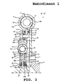
- FIG. 3 is a section view taken on line Y-Y' illustrated in FIG. 1 ;
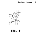
- FIG. 4 is an enlarged partial section view schematically illustrating a connection portion of a first assembly and a second assembly in the torque fluctuation absorbing apparatus according to a second embodiment disclosed here;
- FIG. 5 schematically illustrates the torque fluctuation absorbing apparatus according to a third embodiment disclosed here, where (A) is an enlarged partial section view schematically illustrating a connection portion of a first assembly and a second assembly, (B) is a partial plane view schematically illustrating a structure of a center plate of the first assembly from the viewpoint of arrow z, and (C) is a partial plane view schematically illustrating a structure of a variation of the center plate;
- FIG. 6 is an enlarged partial section view schematically illustrating a connection potion of a first assembly and a second assembly in the torque fluctuation absorbing apparatus according to a fourth embodiment disclosed here;
- FIG. 7 is an enlarged partial section view schematically illustrating a connection portion of a first assembly and a second assembly in the torque fluctuation absorbing apparatus according to a fifth embodiment disclosed here;
- FIG. 8 schematically illustrates a connection portion of a first assembly and a second assembly in the torque fluctuation absorbing apparatus according to a sixth embodiment disclosed here, where (A) is an enlarged partial section view before connection and (B) is an enlarged partial section view after connection;
- FIG. 9 schematically illustrates a connection portion of a first assembly and a second assembly in the torque fluctuation absorbing apparatus according to a seventh embodiment disclosed here, where (A) is an enlarged partial section view before connection, (B) is an enlarged partial section view after connection, and (C) is a partial plane view schematically illustrating a structure of a center plate of the first assembly from the viewpoint of arrow z;
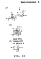
- FIG. 10 schematically illustrates a connection portion of a first assembly and a second assembly in the torque fluctuation absorbing apparatus according to an eighth embodiment disclosed here, where (A) is an enlarged partial section view before connection, (B) is an enlarged partial section view after connection, and (C) is a partial plane view schematically illustrating a structure of a center plate of the first assembly from the viewpoint of arrow z;
- FIG. 11 schematically illustrates a connection portion of a first assembly and a second assembly in the torque fluctuation absorbing apparatus according to a ninth embodiment disclosed here, where (A) is an enlarged partial section view before connection and (B) is an enlarged partial section view after connection;
- FIG. 12 schematically illustrates a connection portion of a first assembly and a second assembly in the torque fluctuation, absorbing apparatus according to a tenth embodiment disclosed here, where (A) is an enlarged partial section view before connection and (B) is an enlarged partial section view after connection;
- FIG. 13 schematically illustrates a connection portion of a first assembly and a second assembly in the torque fluctuation absorbing apparatus according to an eleventh embodiment disclosed here, where (A) is an enlarged partial section view before connection, (B) is an enlarged partial section view after connection, and (C) is a partial plane view schematically illustrating a structure of a center plate of the first assembly from the viewpoint of arrow z;
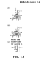
- FIG. 14 schematically illustrates a connection portion of a first assembly and a second assembly in the torque fluctuation absorbing apparatus according to a twelfth embodiment disclosed here, where (A) is an enlarged partial section view before connection, (B) is an enlarged partial section view after connection, and (C) is a partial plane view schematically illustrating a structure of a center plate of the first assembly from the viewpoint of arrow z;
- FIG. 15 schematically illustrates a connection portion of a first assembly and a second assembly in the torque fluctuation absorbing apparatus according to a thirteenth embodiment disclosed here, where (A) is an enlarged partial section view before connection, (B) is an enlarged partial section view after connection, and (C) is a partial plane view schematically illustrating a structure of a center plate of the first assembly from the viewpoint of arrow z;
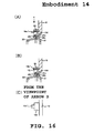
- FIG. 16 schematically illustrates a connection portion of a first assembly and a second assembly in the torque fluctuation absorbing apparatus according to a fourteenth embodiment disclosed here, where (A) is an enlarged partial section view before connection, (B) is an enlarged partial section view after connection, and (C) is a partial plane view schematically illustrating a structure of a center plate of the first assembly from the viewpoint of arrow z;
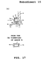
- FIG. 17 schematically illustrates a connection portion of a first assembly and a second assembly in the torque fluctuation absorbing apparatus according to a fifteenth embodiment disclosed here, where (A) is an enlarged partial section view, and (B) is a partial plane view schematically illustrating a structure when a center plate of the first assembly and a C-ring are combined from the viewpoint of arrow z;
- FIG. 18 schematically illustrates a connection portion of a first assembly and a second assembly in the torque fluctuation absorbing apparatus according to a sixteenth embodiment disclosed here, where (A) is an enlarged partial section view, and (B) is a partial plane view schematically illustrating a structure when a center plate of the first assembly and a C-ring are combined from the viewpoint of arrow z ;
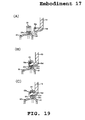
- FIG. 19 schematically illustrates a connection portion of a first assembly and a second assembly in the torque fluctuation absorbing apparatus according to a seventeenth embodiment disclosed here, where (A) is an enlarged partial section view before connection, (B) is an enlarged partial section view during connection, and (C) is an enlarged partial section view after connection;
- FIG. 20 is an enlarged partial section view of an engaged portion of a ring member and a center plate in the torque fluctuation absorbing apparatus according to an eighteenth embodiment disclosed here;
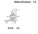
- FIG. 21 is an enlarged partial section view schematically illustrating a connection portion of a first assembly and a second assembly in the torque fluctuation absorbing apparatus according to a nineteenth embodiment disclosed here;
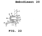
- FIG. 22 is an enlarged partial section view schematically illustrating a connection portion of a first assembly and a second assembly in the torque fluctuation absorbing apparatus according to a twentieth embodiment disclosed here;
- FIG. 23 is an enlarged partial section view schematically illustrating a connection portion of a first assembly and a second assembly in the torque fluctuation absorbing apparatus according to a twenty first embodiment disclosed here;
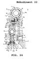
- FIG. 24 is a section view schematically illustrating a structure of the torque fluctuation absorbing apparatus according to a twenty second embodiment disclosed here;
- FIG. 25 is a section view schematically illustrating a structure of the torque fluctuation absorbing apparatus according to a twenty third embodiment disclosed here;
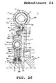
- FIG. 26 is a section view schematically illustrating a structure of the torque fluctuation absorbing apparatus according to a twenty fourth embodiment disclosed here;
- FIG. 27 is a section view schematically illustrating a structure of the torque fluctuation absorbing apparatus according to a twenty fifth embodiment disclosed here.
- FIG. 28 is a section view schematically illustrating a structure of the torque fluctuation absorbing apparatus according to a twenty sixth embodiment disclosed here.
- a torque fluctuation absorbing apparatus includes a first assembly (2 in FIG. 2 ) that absorbs a fluctuating torque generated between a first rotating shaft (6 in FIG. 2 ) and a second rotating shaft (8 in FIG. 2 ) that are arranged coaxially, a first end (10 in FIG. 2 ) of the first assembly being connected to the first rotating shaft from the second rotating shaft side by a first connecting member (7 in FIG. 2 ), a second assembly (3 in FIG. 2 ) that absorbs a fluctuating torque generated between the first rotating shaft and the second rotating shaft, the second assembly being disposed more toward the second rotating shaft side than the first connecting member and a second end (26 in FIG.
- a torque fluctuation absorbing apparatus which can be directly attached to a crank shaft of an engine rather than attaching to the crank shaft via a member such as a flywheel or a drive plate can be obtained.
- FIG. 1 is a plane view schematically illustrating a structure of a torque fluctuation absorbing apparatus according to a first embodiment disclosed here.
- FIG. 2 is a section view taken on line x-x' illustrated in FIG. 1 .
- FIG. 3 is a section view taken on line Y-Y' illustrated in FIG. 1 .
- the torque fluctuation absorbing apparatus 1 is provided between a crank shaft 6 of an engine (not illustrated) and an input shaft 8 of a transmission (not illustrated) so as to absorb (restrain) a fluctuating torque generated between the crank shaft 6 and the input shaft 8.
- the torque fluctuation absorbing apparatus 1 includes a first assembly 2 that absorbs a fluctuating torque generated between the crank shaft 6 and the input shaft 8 and is connected to the crank shaft 6 by a bolt 7, and a second assembly 3 that absorbs a fluctuating torque generated between the crank shaft 6 and the input shaft 8 and is connected to the first assembly 2 and the input shaft 8.
- the first assembly 2 is attached to the crank shaft 6 of the engine, the second assembly 3 is subsequently attached, and then the input shaft 8 of the transmission is mounted thereafter.
- a first end (corresponding to a side plate 10) of the drivetrain is connected to the crank shaft 6 by the bolt 7 from the transmission side (left side in FIG. 2 ) at a radially inward location.
- the first assembly 2 includes, at a radially outward location, a damper portion 2a and a hysteresis portion 2b that function to alleviate torsion.
- the damper portion 2a absorbs torque fluctuations between the crank shaft 6 and the input shaft 8 by means of an elastic force.
- the hysteresis portion 2b alleviates torque fluctuations between the crank shaft 6 and the input shaft 8 by means of a hysteresis torque (for example, frictional force).
- the hysteresis portion 2b is set more radially inward than the damper portion 2a.
- a second end (corresponding to a center plate 13) of the drivetrain is connected to a first end (corresponding to side plates 20 and 21 and a ring member 22) of the drivetrain in the second assembly 3 by a bolt 31 at a location that is more radially inward than the hysteresis portion 2b and more radially outward than the bolt 7.
- the second assembly 3 is connected by the bolt 31. Thereby, a hole through which the bolt 7 is inserted does not need to be provided in the second assembly 3.
- a first end of the drive train (corresponding to side plates 20 and 21 and a ring member 22) is connected to the second end of the drivetrain (corresponding to the center plate 13) in the first assembly 2 by the bolt 31.
- the first end (corresponding to side plates 20 and 21 and a ring member 22) of the second assembly 3 is disposed more toward the transmission side (left side in FIG. 2 ) than the second end of the first assembly 2 (corresponding to the center plate 13).
- the second assembly 3 is disposed more toward the transmission side (left side in FIG. 2 ) than the bolt 7.
- the second assembly 3 includes, at a location that is more radially inward than the bolt 31, a damper portion 3a and a hysteresis portion 3b that function to absorb torsion.
- the damper portion 3a absorbs torque fluctuations between the crank shaft 6 and the input shaft 8 by means of an elastic force. It does not matter whether the damper portion 3a absorbs torque fluctuations before the damper portion 2a of the first assembly 2.
- the hysteresis portion 3b alleviates torque fluctuations between the crank shaft 6 and the input shaft 8 by means of a hysteresis torque (for example, frictional force).
- the hysteresis portion 3b is set more radially inward than the damper portion 3a.
- the second end (corresponding to a hub member 26) of the drivetrain is connected by spline-engagement to the input shaft 8 at a location that is more radially inward than the hysteresis portion 2b.
- the first assembly 2 includes the following main constituent members: a side plate 10, a side plate 11, a coil spring 12, a center plate 13, thrust members 14 and 15, a disc spring 16, and a weld portion 17.
- the side plate 10 is a xing-shaped member, and is a constituent member of the damper portion 2a and the hysteresis portion 2b in the first assembly 2.
- the side plate 10 is connected at an inner circumferential portion thereof to the crank shaft 6 by the bolt 7.
- the bolt 7 can be rotated from the transmission side (left side in FIG. 2 ) using a tool.
- An outer circumferential portion of the side plate 10 includes a bag-shaped accommodating portion 10a for accommodating the coil spring 12 of the damper portion 2a in the first assembly 2.
- the end faces on both sides in the circumferential direction of the accommodating portion 10a can contact with and separate from the ends of the coil spring 12.
- the side plate 10 is formed so as to cover the radially outward side of the damper portion 2a.
- the end of the side plate 10 on the side plate 11 side is closely adhered to the side plate 11 across the entire circumference, and is fixed to the side plate 11 by the weld portion 17.
- the side plate 10 supports an outer circumferential end of a. disc spring 29 at the hysteresis portion 3b that is circumferentially inward relative to the damper portion 2a.
- the side plate 10 engages with the thrust member 15 so that it cannot rotate but can move axially (see FIG. 3 ).
- the side plate 11 is a ring-shaped member, and is a constituent member of the damper portion 2a and the hysteresis portion 2b in the first assembly 2.
- An outer circumferential portion of the side plate 11 is closely adhered to the side plate 10 across the entire circumference, and is fixed to the side plate 10 by the weld portion 17. Thereby, the side plate 11 rotates integrally with the side plate 10.
- the side plate 11 includes, at an intermediate portion thereof, a bag-shaped accommodating portion 11a for accommodating the coil spring 12 of the damper portion 2a in the first assembly 2.
- the end faces on both sides in the circumferential direction of the accommodating portion 11a can contact with and separate from the ends of the coil spring 12.
- the circumferential end faces of the accommodating portion 11a contact both ends of the coil spring 12, and when torsion is being generated in the damper portion 2a, the circumferential end faces contact one end of the coil spring 12.
- the side plate 11 engages with the thrust member 14 at the hysteresis portion 2b that is circumferentially inward than the damper portion 2a, so that the side plate 11 cannot rotate but can move axially (see FIG. 3 ).
- the coil spring 12 is accommodated in the accommodating portions 10a and 11a of the side plates 10 and 11 and a window portion 13a of the center plate 13, and is in separatable contact with the accommodating portions l0a and 11a at its ends and the window portion 13a.
- the coil spring 12 contracts when torsion (torsion between the side plates 10 and 11 and the center plate 13) is generated in the damper potion 2a.
- An arc spring that is curved in the circumferential direction may be used as the coil spring 12 so as to realize a large torsion.
- the center plate 13 is a ring-shaped member, and is a constituent member of the damper portion 2a and the hysteresis portion 2b in the first assembly 2.
- the center plate 13 is connected at an inner circumferential portion thereof to first end (the side plates 20 and 21 and the ring member 22) of the second assembly 3 by the bolt 31 (see FIG. 2 ). Thereby, the center plate 13 rotates integrally with the side plates 20 and 21 and the ring member 22.
- the center plate 13 is formed so as not to conflict with a rivet 30 that connects the side plates 20 and 21 and the ring member 22 (see FIG. 3 ).
- An outer circumferential portion of the center plate 13 includes a cutout window portion 13a for accommodating the coil spring 12 of the damper portion 2a.
- the end faces on both sides in the circumferential direction of the window portion 13a can contact with and separate from the coil spring 12.
- the circumferential end faces of the window portion 13a contact both ends of the coil spring 12, and when torsion is being generated in the damper portion 2a, the circumferential end faces contact one end of the coil spring 12.
- the center plate 13 is slidably sandwiched by the thrust members 14 and 15 at the hysteresis portion 2b which is an intermediate portion that is more radially inward than the damper portion 2a and more radially outward than the bolt 31.
- the thrust member 14 is a ring-shaped member, and is a constituent part of the hysteresis portion 2b in the first assembly 2.
- the thrust member 14 is disposed between the side plate 11 and the center plate 13.
- the thrust member 14 engages with the side plate 11 so that it cannot rotate but can move axially, and the thrust member 14 is slideably pressed against a flange 26b (see FIG. 3 ).
- the thrust member 15 is a ring-shaped member, and is a constituent part of the hysteresis portion 2b in the first assembly 2.
- the thrust member 15 is disposed between the disc spring 16 and the center plate 13.
- the thrust member 15 is biased toward the center plate 13 by the disc spring 16.
- the thrust member 15 is slidably pressed against the center plate 13.
- the thrust member 15 engages with the disc spring 16 so that it cannot rotate but can move axially (see FIG. 2 ).
- the thrust member 15 engages with the side plate 10 so that it cannot rotate but can move axially (see FIG. 3 ).
- the disc spring 16 is a disc-shaped spring that biases the thrust member 15 toward the center plate 13, and is a constituent part of the hysteresis portion 2b.
- the disc spring 16 is disposed between the thrust member 15 and the side plate 10.
- the disc spring 16 engages at an inner circumferential end thereof with the thrust member 15 so that it cannot rotate but can move axially.
- the disc spring 16 is supported at its outer circumferential end by the side plate 10, and biases the thrust member 15 toward the center plate 13 at its inner circumferential end.
- the weld portion 17 is a portion that welds the side plate 10 and the side plate 11 to each other, The weld portion 17 is formed across the entire circumference along an outer circumference of a portion at which the side plate 10 and the side plate 11 join together.
- the second assembly 3 includes the following main constituent members: a side plate 20, a side plate 21, a ring member 22, a seat member 23, a coil spring 24, a cushion member 25, a hub member 26, thrust members 27 and 28, a disc spring 29, and a rivet 30.
- the side plate 20 is a ring-shaped member disposed on the transmission side (left side in FIG. 2 ) of a flange 26b of the hub member 26, and is a constituent member of the damper portion 3a and the hysteresis portion 3b in the second assembly 3.
- the side plate 20 is integrally fixed on an outer circumferential portion thereof to the ring member 22 and the side plate 21 by the rivet 30 (see FIG. 3 ).
- the side plate 20 is connected to the ring member 22, the side plate 21, and the center plate 13 by the bolt 31 at a portion that is displaced in the circumferential direction from the rivet 30 (see FIG. 2 ).
- the side plate 20 includes, in the damper portion 3a which is an intermediate portion, a window portion 20a for accommodating the coil spring 24 and the seat member 23.
- the end face in the circumferential direction of the window portion 20a is in separatable contact with the seat member 23.
- the side plate 20 engages with the thrust member 27 so that it cannot rotate but can move axially.
- the side plate 20 is rotatably supported at its inner circumferential end by the hub member 26 (hub portion 26a) via the thrust member 27.
- the side plate 21 is a ring-shaped member disposed on the engine side (right side in FIG. 2 ) of the flange 26b of the hub member 26, and is a constituent member of the damper portion 3a and the hysteresis portion 3b in the second assembly 3.
- the side plate 21 is integrally fixed on an outer circumferential portion thereof to the ring member 22 and the side plate 20 by the rivet 30 (see FIG. 3 ).
- the side plate 21 is connected to the ring member 22, the side plate 20, and the center plate 13 by the bolt 31 at a portion that is displaced in the circumferential direction from the rivet 30 (see FIG. 2 ).
- the side plate 21 includes, in the damper portion 3a which is an intermediate portion, a window portion 21a for accommodating the coil spring 24 and the seat member 23.
- the end face in the circumferential direction of the window portion 21a is in separatable contact with the seat member 23.
- the side plate 21 supports an outer circumferential end of the disc spring 29.
- the side plate 21 engages with the thrust member 28 so that it cannot rotate but can move axially.
- the side plate 21 is rotatably supported at its inner circumferential end by the hub member 26 (hub portion 26a) via the thrust member 28.
- the ring member 22 is a ring-shaped member disposed between the side plates 20 and 21.
- the ring member 22 includes, at its inner circumferential portion, a plurality of convex portions 22a that protrude radially inward.
- the convex portions 22a control the torsion of the damper portion 3a in the second assembly 3 at a prescribed angle, and they control the torsion of the damper portion 3a by hitting against convex portions 26d of the hub member 26 when torsion is generated in the damper portion 3a.
- the convex portions 22a are sandwiched between the side plate 20 and the side plate 21, and are integrally fixed to the side plate 20 and the side plate 21 by the rivet 30 (see FIG. 3 ).
- the ring member 22 is connected to the side plates 20 and 21 and the center plate 13 by the bolt 31 at a portion that is displaced in the circumferential direction from the rivet 30 (see FIG. 2 ).
- the seat member 23 is a constituent part of the damper portion 3a in the second assembly 3.
- the seat member 23 is accommodated by the window portions 20a, 21a, and 26c formed respectively on the side plates 20 and 21 and the hub member 26 (flange 26b), and the seat member 23 is disposed between the end faces in the circumferential direction of the window portions 20a, 21a, and 26c and the end of the coil spring 24.
- a resin can be used for the seat member 23 in order to reduce the wear on the coil spring 24.
- the coil spring 24 is a constituent part of the damper portion 3a in the second assembly 3.
- the coil spring 24 is accommodated by the window portions 20a, 21a, and 26c formed respectively on the side plates 20 and 21 and the hub member 26 (flange 26b), and is in contact with the seat members 23 disposed on both ends of the coil spring 24.
- the coil spring 24 contracts when torsion (torsion between the side plates 20 and 21 and the hub member 26) is generated in the damper portion 3a.
- the coil spring 24 may be formed to have a straight shape, or may be formed into the straight shape and then bent while being assembled. Alternatively, an arc spring that is curved in the circumferential direction may be used so as to realize a large torsion.
- the cushion member 25 is a member that absorbs a shock when the convex portions 26d of the hub member 26 hit against the convex portions 22a of the ring member 22 when torsion is generated in the damper portion 3a in the second assembly 3.
- the cushion member 25 is disposed inside the coil spring 24.
- the cushion member 25 is in a free state until it is sandwiched between a pair of seat members 23 when torsion is generated in the damper portion 3a, and is sandwiched between the pair of seat members 23 before the convex portions 26d of the hub member 26 hit against the convex portions 22a of the ring member 22.
- the hub member 26 is a member that outputs a rotative power from the damper portion 3a and the hysteresis portion 3b in the second assembly 3 to the transmission, and is a constituent member of the damper portion 3a and the hysteresis portion 3b.
- the hub member 26 includes the flange 26b that extends radially outward from a predetermined location on the outer periphery of the hub portion 26a.
- An inner circumferential surface of the hub portion 26a is spline-engaged (engaged so that it cannot rotate but can move axially) with the input shaft 8 of the transmission.
- the outer periphery of the hub portion 26a rotatably supports the side plate 20 via the thrust member 27, and rotatably supports the side plate 21 via the thrust member 28.
- the flange 26b includes, in the damper portion 3a, a window portion 26c for accommodating the coil spring 24 and the seat member 23. The circumferential end face of the window portion 26c is in separatably contact with the seat member 23.
- the flange 26b is slidably sandwiched by the thrust members 27 and 28 at a surface in the axial direction of the hysteresis portion 3b that is radially inward relative to the damper portion 3a.
- the outer circumferential end of the flange 26b includes a plurality of convex portions 26d that protrude radially outward.
- the convex portions 26d are portions that control the torsion of the damper portion 3a at a prescribed angle, and they control the torsion of the damper portion 3a by hitting against the convex portions 22a of the ring member 22 when torsion is generated in the damper portion 3a.
- the thrust member 27 is a ring-shaped member disposed between the side plate 20 and the hub member 26, and is a constituent part of the hysteresis portion 3b in the second assembly 3.
- the thrust member 27 is positioned between the side plate 20 and the flange 26b in the axial direction.
- the thrust member 27 engages with the side plate 20 so that it cannot rotate but can move axially, and is slidably pressed against the flange 26b.
- the thrust members 27 is also interposed between the side plate 20 and the hub portion 26a in the radial direction, and serves as a sliding bearing (a bush) for rotatably supporting the side plate 20 on the hub portion 26a.
- the thrust member 28 is a ring-shaped member disposed between the side plate 21 and the hub member 26, and is a constituent part of the hysteresis portion 3b in the second assembly 3.
- the thrust member 28 is positioned between the disc spring 29 and the flange 26b in the axial direction.
- the thrust member 28 is biased toward the flange 26b by the disc spring 29, and is slidably pressed against the flange 26b.
- the thrust member 28 engages with the side plate 21 so that it cannot rotate but can move axially.
- the thrust member 28 is also interposed between the side plate 21 and the hub portion 26a in the radial direction, and serves as a sliding bearing (a bush) for rotatably supporting the side plate 21 on the hub portion 26a.
- the disc spring 29 is a disc-shaped spring that is disposed between the thrust member 28 and the side plate 21, and biases the thrust member 28 toward the flange 26b.
- the disc spring 29 is a constituent part of the hysteresis portion 3b in the second assembly 3.
- the disc spring 29 engages at its inner circumferential end with the thrust member 28 so that it cannot rotate but can move axially.
- the disc spring 29 is supported at its outer circumferential end by the side plate 21, and biases the thrust member 28 toward the flange 26b at its inner circumferential portion.
- the rivet 30 is a member for integrally fixing the side plates 20 and 21 and the ring member 22 to each other.
- the bolt 31 is a second connecting member that connects the second end of the first assembly 2 (corresponding to the center plate 13) to the first end of the second assembly 3 (corresponding to the side plates 20 and 21 and the ring member 22).
- the bolt 31 can be rotated from the transmission side (left side in FIG. 2 ) using a tool.
- the torque fluctuation absorbing apparatus 1 by dividing the torque fluctuation absorbing apparatus 1 into the first assembly 2 and the second assembly 3 and configuring the assemblies so that the second end of the first assembly 2 can be connected to the first end of the second assembly 3, a work hole through which the bolt 7 for connecting to the crank shaft 6 is inserted can be eliminated from the torque fluctuation absorbing apparatus 1, and thus the strength of the apparatus can be ensured.
- FIG. 4 is an enlarged partial section view schematically illustrating a connection portion of a first assembly and a second assembly in the torque fluctuation absorbing apparatus according to a second embodiment disclosed here.
- the second embodiment is a variation of the first embodiment.
- the second connecting member for connecting the second end (corresponding to the center plate 13) of the first assembly (corresponding to 2 in FIG. 2 ) to the first end (corresponding to the side plates 20 and 21 and the ring member 22) of the second assembly (corresponding to 3 in FIG. 2 )
- a cylindrical portion 13b that protrudes toward the transmission side (left side in FIG.
- the second end (corresponding to the center plate 13) of the first assembly (corresponding to 2 in FIG. 2 ) is connected to the first end (corresponding to the side plates 20 and 21 and the ring member 22) of the second assembly (corresponding to 3 in FIG.
- the side plates 20 and 21 and the ring member 22 are integrally fixed to each other by a rivet 32 in addition to the rivet (corresponding to 30 in FIG. 3 ).
- Other structures of the second embodiment are identical to those of the first embodiment.
- FIG. 5 schematically illustrates the torque fluctuation absorbing apparatus according to a third embodiment disclosed here, where (A) is an enlarged partial section view schematically illustrating a connection portion of a first assembly and a second assembly, (B) is a partial plane view schematically illustrating a structure of a center plate of the first assembly from the viewpoint of arrow z, and (C) is a partial plane view schematically illustrating a structure of a variation of the center plate.
- the third embodiment is a variation of the first embodiment.
- the second connecting member for connecting the second end (corresponding to the center plate 13) of the first assembly (corresponding to 2 in FIG. 2 ) to the first end (corresponding to the side plates 20 and 21 and the ring member 22) of the second assembly (corresponding to 3 in FIG. 2 ) instead of using a bolt (31 in FIG. 2 ), a plurality of protruding portions 13d that protrude toward the transmission side (left side in FIG. 5 ) are provided on the inner circumferential end of the center plate 13, and holes 20c, 21c, and 22c are respectively provided to the side plates 20 and 21 and the ring member 22.
- the protruding portions 13d are inserted through the holes 20c, 21c, and 22c, and a claw portion 13e is provided on a radially outward surface of the distal end portion of the protruding portions 13d.
- the side plates 20 and 21 and the ring member 22 are configured so that they do not fall out from the protruding portions 13d due to the claw portions 13e.
- a surface on the engine side (right side in FIG. 5 ) of the side plate 21 abuts the main body of the center plate 13.
- a surface on the engine side (right side in FIG. 5 ) of the claw portion 13e is formed so as to hook onto the side plate 20.
- the side plates 20 and 21 and the ring member 22 cannot move axially relative to the center plate 13.
- the surfaces on both sides in the circumferential direction of the protruding portion 13d abut the holes 20c, 21c, and 22c.
- the side plates 20 and 21 and the ring member 22 cannot move in the circumferential direction relative to the center plate 13.
- a radially outward surface of the protruding portion 13d abuts the holes 20c, 21c, and 22c.
- the side plates 20 and 21 and the ring member 22 cannot move radially relative to the center plate 13.
- a surface on the transmission side (left side in FIG. 5 ) of the claw portion 13e is tapered in order to make the protruding portion 13d easily elastically deformable radially inward when the protruding portion 13d is inserted through the holes 20c, 21c, and 22c.
- the holes 20c, 21c, and 22c are set larger in the radial direction than the cross-section of the protruding portion 13d so that the protruding portion 13d (including the claw portion 13e) can pass therethrough when the protruding portion 13d is elastically deformed radially inward.
- a surface on the transmission side (left side in FIG. 5 ) of the claw portion 13e can be formed as, for example, a rectangular-shaped claw portion 13e (see FIG.
- the apparatus is designed on the assumption that the protruding portion 13d will elastically deform radially inward.
- the protruding portion can elastically deform radially outward, and the claw portion can be provided on a surface on the radially inward side of the distal end portion of the protruding portion.
- the second assembly can be mounted to the first assembly without any elaborate facilities such as assembling by a bolt or rivet.
- FIG. 6 is an enlarged partial section view schematically illustrating a connection portion of a first assembly and a second assembly in the torque fluctuation absorbing apparatus according to a fourth embodiment disclosed here.
- the fourth embodiment is a variation of the third embodiment.
- the protruding portion (13d in FIG. 5 ) provided to the inner circumferential end of the center plate 13 are configured as a forked protruding portion 13f including two distal end portions that can elastically deform in the radial direction.
- a claw portion 13g is provided to a surface (excluding the surface on the groove side between the distal end portions) in the radial direction of each distal end portion of the forked protruding portion 13f, and thereby the side plates 20 and 21 and the ring member 22 are configured so that they do not fall out from the forked protruding portion 13f due to the claw portions 13g.
- a surface on the engine side (right side in FIG. 6 ) of the side plate 21 abuts the main body of the center plate 13.
- a surface on the engine side (right side in FIG. 6 ) of each claw portion 13g is formed so as to hook onto the side plate 20.
- the side plates 20 and 21 and the ring member 22 cannot move axially relative to the center plate 13.
- the surfaces on both sides in the circumferential direction of the forked protruding portion 13f abut the holes 20c, 21c, and 22c. Thereby, the side plates 20 and 21 and the ring member 22 cannot move in the circumferential direction relative to the center plate 13.
- each claw portion 13g A surface on the transmission side (left side in FIG. 6 ) of each claw portion 13g is tapered in order to make each distal end portion in the forked protruding portion 13f easily elastically deformable toward the groove side (groove between the distal end portions) when the forked protruding portion 13f is inserted through the holes 20c, 21c, and 22c.
- Other structures of the fourth embodiment are identical to those of the third embodiment.
- FIG. 7 is an enlarged partial section view schematically illustrating a connection portion of a first assembly and a second assembly in the torque fluctuation absorbing apparatus according to a fifth embodiment disclosed here.
- the fifth embodiment is a variation of the fourth embodiment.
- the two distal end portions of a forked protruding portion 13f' are elastically deformable in the circumferential direction rather than the radial direction, and a claw portion 13g' is provided to a surface (excluding the surface on the groove side between the distal end portions) in the circumferential direction of each distal end portion of the forked protruding portion 13f'.
- the side plates 20 and 21 and the ring member 22 are configured so that they do not fall out from the forked protruding portion 13f' due to the claw portions 13g'.
- a surface on the engine side (right side in FIG. 7 ) of the side plate 21 abuts the main body of the center plate 13.
- a surface on the engine side (right side in FIG. 7 ) of each claw portion 13g' is formed so as to hook onto the side plate 20.
- the side plates 20 and 21 and the ring member 22 cannot move axially relative to the center plate 13.
- the surfaces on both sides in the circumferential direction of the forked protruding portion 13f' abut the holes 20c, 21c, and 22c. Thereby, the side plates 20 and 21 and the ring member 22 cannot move in the circumferential direction relative to the center plate 13.
- a surface(s) in the radial direction (one or both of radially outward and radially inward) of the forked protruding portion 13f' abuts the holes 20c, 21c, and 22c. Thereby, the side plates 20 and 21 and the ring member 22 cannot move radially relative to the center plate 13.
- each claw portion 13g' A surface on the transmission side (left side in FIG.7 ) of each claw portion 13g' is tapered in order to make each distal end portion in the forked protruding portion 13f' easily elastically deformable toward the groove side (groove between the distal end portions) when the forked protruding portion 13f is inserted through the holes 20c, 21c, and 22c.
- Other structures of the fifth embodiment are identical to those of the fourth embodiment.
- FIG. 8 schematically illustrates a connection portion of a first assembly and a second assembly in the torque fluctuation absorbing apparatus according to a sixth embodiment disclosed here, where (A) is an enlarged partial section view before connection and (B) is an enlarged partial section view after connection.
- the sixth embodiment is a variation of the third embodiment.
- the claw portion (13g in FIG. 5 ) is eliminated from the protruding portion 13d provided on the inner circumferential end of the center plate 13, and a hook portion 13h that is curved and protrudes radially outward is formed on the distal end of the protruding portion 13d by press molding.
- the side plates 20 and 21 and the ring member 22 are configured so that they do not fall out from the protruding portion 13d due to the hook portion 13h.
- a surface on the engine side (right side in FIG. 8 ) of the side plate 21 abuts the main body of the center plate 13.
- the hook portion 13h is formed so as to hook onto the side plate 20.
- the side plates 20 and 21 and the ring member 22 cannot move axially relative to the center plate 13.
- the surfaces on both sides in the circumferential direction of the protruding portion 13d abut the holes 20c, 21c, and 22c.
- the side plates 20 and 21 and the ring member 22 cannot move in the circumferential direction relative to the center plate 13.
- a radially outward surface of the protruding portion 13d abuts the holes 20c, 21c, and 22c.
- the side plates 20 and 21 and the ring member 22 cannot move radially relative to the center plate 13.
- the holes 20c, 21c, and 22c are set larger in the radial direction than the cross-section of the protruding portion 13d so that the protruding portion 13d (including the hook portion 13h) can pass therethrough when the protruding portion 13d is elastically deformed radially inward.
- Other structures of the sixth embodiment are identical to those of the third embodiment.
- the apparatus is designed on the assumption that the protruding portion 13d will elastically deform radially inward.
- the protruding portion can elastically deform radially outward, and the hook portion can be configured to curve and protrude radially inward (the same applies to the seventh to ninth embodiments).
- FIG, 9 schematically illustrates a connection portion of a first assembly and a second assembly in the torque fluctuation absorbing apparatus according to a seventh embodiment disclosed here, where (A) is an enlarged partial section view before connection, (B) is an enlarged partial section view after connection, and (C) is a partial plane view schematically illustrating a structure of a center plate of the first assembly from the viewpoint of arrow z.
- the seventh embodiment is a variation of the sixth embodiment.
- the width in the circumferential direction of a portion of a hook portion 13h' formed on the distal end of the protruding portion 13d is made smaller than the width in the circumferential direction of a portion of the hook portion (13h in FIG. 8 ) of the sixth embodiment so as to make the hook portion 13h' easily elastically deformable.
- Other structures of the seventh embodiment are identical to those of the sixth embodiment.
- the portions on both sides in the circumferential direction of the hook portion 13h' are made into a cutout shape.
- only one side in the circumferential direction of the hook portion can be made into a cutout shape, or an intermediate portion of the hook portion can be made into a cutout shape.
- FIG. 10 schematically illustrates a connection portion of a first assembly and a second assembly in the torque fluctuation absorbing apparatus according to an eighth embodiment disclosed here, where (A) is an enlarged partial section view before connection, (B) is an enlarged partial section view after connection, and (C) is a partial plane view schematically illustrating a structure of a center plate of the first assembly from the viewpoint of arrow z.
- the eighth embodiment is a variation of the sixth embodiment.
- a hole 13i (a cutout is also possible) that penetrates in the axial direction is formed in the protruding portion 13d at a portion disposed within the holes 20c, 21c, 22c.
- the hole 13i is not limited to one per protruding portion 13d, and a plurality of holes 13i can be formed in each protruding portion 13d.
- Other structures of the eighth embodiment are identical to those of the sixth embodiment.
- FIG. 11 schematically illustrates a connection portion of a first assembly and a second assembly in the torque fluctuation absorbing apparatus according to a ninth embodiment disclosed here, where (A) is an enlarged partial section view before connection and (B) is an enlarged partial section view after connection.
- the ninth embodiment is a variation of the sixth embodiment.
- the width (thickness) in the radial direction of a portion of a hook portion 13h" formed on the distal end of the protruding portion 13d is made smaller (thinner) than the width in the radial direction of a portion of the hook portion (13h in FIG. 8 ) of the sixth embodiment so as to make the hook portion 13h" easily elastically deformable.
- Other structures of the ninth embodiment are identical to those of the sixth embodiment.
- a radially inward portion of the hook portion 13h" is made into a cutout shape.
- a radially outward portion can be made into a cutout shape if the hook portion hooks on at a radially inward position.
- FIG. 12 schematically illustrates a connection portion of a first assembly and a second assembly in the torque fluctuation absorbing apparatus according to a tenth embodiment disclosed here, where (A) is an enlarged partial section view before connection and (B) is an enlarged partial section view after connection.
- the tenth embodiment is a variation of the third embodiment.
- the claw portion (13e in FIG. 5 ) is eliminated from the protruding portion 13d, and a bent portion 13j that is bent radially outward (radially inward is also possible) is formed on the distal end of the protruding portion 13d that is inserted through the holes 20c, 21c, and 22c.
- the side plates 20 and 21 and the ring member 22 are configured so that they do not fall out from the protruding portion 13d due to the bent portion 13j.
- a surface on the engine side (right side in FIG. 12 ) of the side plate 21 abuts the main body of the center plate 13.
- a surface on the engine side (right side in FIG. 12 ) of the bent portion 13j is formed so as to abut the side plate 20.
- the side plates 20 and 21 and the ring member 22 cannot move axially relative to the center plate 13.
- the surfaces on both sides in the circumferential direction of the protruding portion 13d abut the holes 20c, 21c, and 22c. Thereby, the side plates 20 and 21 and the ring member 22 cannot move in the circumferential direction relative to the center plate 13.
- a surface(s) in the radial direction (one or both of radially outward and radially inward) of the protruding portion 13d abut (s) the holes 20c, 21c, and 22c. Thereby, the side plates 20 and 21 and the ring member 22 cannot move radially relative to the center plate 13.
- Other structures of the tenth embodiment are identical to those of the third embodiment.
- a caulking portion can be used instead of the bent portion 13j.
- the bent portion 13j can be bent in the circumferential direction instead of the radial direction.
- FIG. 13 schematically illustrates a connection portion of a first assembly and a second assembly in the torque fluctuation absorbing apparatus according to an eleventh embodiment disclosed here, where (A) is an enlarged partial section view before connection, (B) is an enlarged partial section view after connection, and (C) is a partial plane view schematically illustrating a structure of a center plate of the first assembly from the viewpoint of arrow z.
- the eleventh embodiment is a variation of the tenth embodiment.
- a hole 13k (a cutout is also possible) that penetrates in the radial direction is formed at the portion where the bent portion 13j is to be formed in the protruding portion 13d so as to make the bent portion 13j easier to form.
- the hole 13k is not limited to one per protruding portion 13d, and a plurality of holes 13k can be formed in each protruding portion 13d.
- Other structures of the eleventh embodiment are identical to those of the tenth embodiment.
- FIG. 14 schematically illustrates a connection portion of a first assembly and a second assembly in the torque fluctuation absorbing apparatus according to a twelfth embodiment disclosed here, where (A) is an enlarged partial section view before connection, (B) is an enlarged partial section view after connection, and (C) is a partial plane view schematically illustrating a structure of a center plate of the first assembly from the viewpoint of arrow z.
- the twelfth embodiment is a variation of the tenth embodiment.
- a groove 131 along the circumferential direction is formed at the portion where the bent portion 13 j is to be formed in the protruding portion 13d so as to make the bent portion 13j easier to form.
- the groove 131 does not have to be formed only on a radially outward surface of the protruding portion 13d as in FIG. 14 , but can also be formed on a radially inward surface or on a surface on one or both sides in the circumferential direction.
- Other structures of the twelfth embodiment are identical to those of the tenth embodiment.
- FIG. 15 schematically illustrates a connection portion of a first assembly and a second assembly in the torque fluctuation absorbing apparatus according to a thirteenth embodiment disclosed here, where (A) is an enlarged partial section view before connection, (B) is an enlarged partial section view after connection, and (C) is a partial plane view schematically illustrating a structure of a center plate of the first assembly from the viewpoint of arrow z.
- the thirteenth embodiment is a variation of the tenth embodiment.
- the width in the circumferential direction of the portion where the bent portion 13j is to be formed in the protruding portion 13d is made into a convex portion 13m whose width is smaller than the width in the circumferential direction of the bent portion (13j in FIG. 12 ) in the tenth embodiment (a width identical to that in the circumferential direction of the protruding portion 13d in FIG. 12 ) so as to make the bent portion 13j easier to form.
- Other structures of the thirteenth embodiment are identical to those of the tenth embodiment.
- the portions on both sides in the circumferential direction of the convex portion 13m are made into a cutout shape.
- only one side in the circumferential direction of the convex portion can be made into a cutout shape, or an intermediate portion of the convex portion can be made into a cutout shape.
- FIG. 16 schematically illustrates a connection portion of a first assembly and a second assembly in the torque fluctuation absorbing apparatus according to a fourteenth embodiment disclosed here, where (A) is an enlarged partial section view before connection, (B) is an enlarged partial section view after connection, and (C) is a partial plane view schematically illustrating a structure of a center plate of the first assembly from the viewpoint of arrow z.
- the fourteenth embodiment is a variation of the thirteenth embodiment.
- the width (thickness) in the radial direction of the portion where the bent portion 13j is to be formed in the protruding portion 13d is made into a convex portion 13m' whose width is smaller (thinner) than the width in the radial direction of the bent portion (13j in FIG. 12 ) in the tenth embodiment (a width identical to that in the radial direction of the protruding portion 13d in FIG. 12 ) so as to make the bent portion 13j easier to form.
- Other structures of the fourteenth embodiment are identical to those of the thirteenth embodiment.
- a radially inward portion of the convex portion 13m' is made into a cutout shape.
- a radially outward portion can be made into a cutout shape if the bent portion hooks on at a radially inward position.
- the width in the circumferential direction of the convex portion 13m' is made smaller than the width in the circumferential direction of the protruding portion 13d.
- the width in the circumferential direction of the convex portion 13m' can be made identical to the width in the circumferential direction of the protruding portion 13d.
- FIG. 17 schematically illustrates a connection portion of a first assembly and a second assembly in the torque fluctuation absorbing apparatus according to a fifteenth embodiment disclosed here, where (A) is an enlarged partial section view, and (B) is a partial plane view schematically illustrating a structure when a center plate of the first assembly and a c-ring are combined from the viewpoint of arrow z.
- the fifteenth embodiment is a variation of the third embodiment.
- the claw portion (13e in FIG. 5 ) is eliminated from the protruding portion 13d
- a groove 13n is formed on the periphery (surfaces in the radial direction and the circumferential direction) of the distal end portion of the protruding portion 13d that is inserted through the holes 20c, 21c, and 22c, and a C-ring 33 (other stoppers such as a snap ring, a temporary stop rivet, or the like are possible) is fitted onto the groove 13n.
- the side plates 20 and 21 and the ring member 22 are configured so that they do not fall out from the protruding portion 13d due to the C-ring 33.
- a surface on the engine side (right side in FIG. 17 ) of the side plate 21 abuts the main body of the center plate 13.
- a surface on the engine side (right side in FIG. 17 ) of the C-ring 33 abuts the side plate 20.
- the side plates 20 and 21 and the ring member 22 cannot move axially relative to the center plate 13.
- the surfaces on both sides in the circumferential direction of the protruding portion 13d abut the holes 20c, 21c, and 22c.
- the side plates 20 and 21 and the ring member 22 cannot move in the circumferential direction relative to the center plate 13.
- a surface (s) in the radial direction (one or both of radially outward and radially inward) of the protruding portion 13d abut(s) the holes 20c, 21c, and 22c. Thereby, the side plates 20 and 21 and the ring member 22 cannot move radially relative to the center plate 13.
- Other structures of the fifteenth embodiment are identical to those of the third embodiment.
- FIG. 18 schematically illustrates a connection portion of a first assembly and a second assembly in the torque fluctuation absorbing apparatus according to a sixteenth embodiment disclosed here, where (A) is an enlarged partial section view, and (B) is a partial plane view schematically illustrating a structure when a center plate of the first assembly and a C-ring are combined from the viewpoint of arrow z.
- the sixteenth embodiment is a variation of the fifteenth embodiment.
- a groove I3n' formed on the distal end portion of the protruding portion 13d is formed on the surfaces on both sides in the circumferential direction (both sides in the radial direction is also possible), and a C-ring 33' (other stoppers such as a snap ring, a temporary stop rivet, or the like are possible) is fitted onto the groove 13n'.
- the side plates 20 and 21 and the ring member 22 are configured so that they do not fall out from the protruding portion 13d due to the C-ring 33'.
- Other structures of the sixteenth embodiment are identical to those of the fifteenth embodiment.
- FIG. 19 schematically illustrates a connection portion of a first assembly and a second assembly in the torque fluctuation absorbing apparatus according to a seventeenth embodiment disclosed here, where (A) is an enlarged partial section view before connection, (B) is an enlarged partial section view during connection, and (C) is an enlarged partial section view after connection.
- the seventeenth embodiment is a variation of the third embodiment.
- the claw portion (13e in FIG. 5 ) is eliminated from the protruding portion 13d, an elastic body 13o is retained on a groove formed on a radially outward surface (a radially inward surface or the surfaces on both sides in the circumferential direction is also possible) of the protruding portion 13d.
- the side plates 20 and 21 and the ring member 22 are configured so that they do not fall out from the protruding portion 13d due to the elastic body 13o.
- the elastic body 13o includes a portion that protrudes from a radially outward surface of the protruding portion 13d, and this protruding portion hooks onto the side plate 20. The elastic body 13o elastically deforms when the protruding portion 13d is inserted through the holes 20c, 21c, and 22c (see FIG. 19 (B) ).
- a surface on the engine side (right side in FIG. 19 ) of the side plate 21 abuts the main body of the center plate 13.
- the protruding portion of the elastic body 13o abuts the side plate 20.
- the side plates 20 and 21 and the ring member 22 cannot move axially relative to the center plate 13.
- the surfaces on both sides in the circumferential direction of the protruding portion 13d abut the holes 20c, 21c, and 22c. Thereby, the side plates 20 and 21 and the ring member 22 cannot move in the circumferential direction relative to the center plate 13.
- a surface(s) in the radial direction (one or both of radially outward and radially inward) of the protruding portion 13d abut(s) the holes 20c, 21c, and 22c. Thereby, the side plates 20 and 21 and the ring member 22 cannot move radially relative to the center plate 13.
- Other structures of the seventeenth embodiment are identical to those of the third embodiment.
- FIG. 20 is an enlarged partial section view of an engaged portion of a ring member and a center plate in the torque fluctuation absorbing apparatus according to an eighteenth embodiment disclosed here.
- the eighteenth embodiment is a variation of the third embodiment.
- the claw portion (13e in FIG. 5 ) is eliminated from the protruding portion 13d, a groove 13p is provided on a radially outward surface of the protruding portion 13d, and a ring member 34 is fitted onto the groove 13p.
- a surface on the engine side (right side in FIG. 20 ) of the side plate 21 abuts the main body of the center plate 13.
- the ring member 34 abuts the side plate 20.
- the side plates 20 and 21 and the ring member 22 cannot move axially relative to the center plate 13.
- the surfaces on both sides in the circumferential direction of the protruding portion 13d abut the holes 20c, 21c, and 22c.
- the side plates 20 and 21 and the ring member 22 cannot move in the circumferential direction relative to the center plate 13.
- a surface (s) in the radial direction (one or both of radially outward and radially inward) of the protruding portion 13d abut (s) the holes 20c, 21c, and 22c.
- Other structures of the eighteenth embodiment are identical to those of the third embodiment.
- FIG. 21 is an enlarged partial section view schematically illustrating a connection portion of a first assembly and a second assembly in the torque fluctuation absorbing apparatus according to a nineteenth embodiment disclosed here.
- the nineteenth embodiment is a variation of the first embodiment.
- the second connecting member for connecting the second end (corresponding to the center plate 13) of the first assembly (corresponding to 2 in FIG. 2 ) to the first end (corresponding to the side plates 20 and 21 and the ring member 22) of the second assembly (corresponding to 3 in FIG. 2 ) instead of using a bolt (31 in FIG. 2 ), the side plates 20 and 21 and the ring member 22 are integrally fixed with a rivet 36, and a hole 13q (a cutout is also possible) is formed on the center plate 13 so that the center plate 13 does not conflict with the rivet 36.
- the side plate 21 is then abutted to the center plate 13 and a weld portion 37 is formed to weld the outer circumferential end of the side plate 21 to the center plate 13. Thereby, the side plates 20 and 21 and the ring member 22 are connected to the center plate 13.
- the hole 13q can also be used to position a jaw portion (head portion) of the rivet 36.
- Other structures of the nineteenth embodiment are identical to those of the first embodiment.
- FIG. 22 is an enlarged partial section view schematically illustrating a connection portion of a first assembly and a second assembly in the torque fluctuation absorbing apparatus according to a twentieth embodiment disclosed here.
- the twentieth embodiment is a variation of the first embodiment.
- the second connecting member for connecting the second end (corresponding to the center plate 13) of the first assembly (corresponding to 2 in FIG. 2 ) to the first end (corresponding to the side plates 20 and 21 and the ring member 22) of the second assembly (corresponding to 3 in FIG. 2 ) instead of using a bolt (31 in FIG. 2 ), a pin member 38 and a C-ring 39 (other stoppers such as a snap ring, a temporary stop rivet, or the like are possible) are used to connect the side plates 20 and 21 and the ring member 22 to the center plate 13.
- Holes 20c, 21c, 22c, and 13r through which a pin portion of the pin member 38 is inserted are formed respectively in the side plates 20 and 21, the ring member 22, and the center plate 13, and the pin portion of the pin member 38 is inserted into the holes 20c, 21c, 22c, and 13r so that a jaw portion 38a of the pin member 38 is on the engine side (right side in FIG. 22 ).
- a groove 38b is formed on a peripheral surface of the distal end of the pin portion of the pin member 38, and the C-ring 39 is fitted onto the groove 38b.
- FIG. 23 is an enlarged partial section view schematically illustrating a connection portion of a first assembly and a second assembly in the torque fluctuation absorbing apparatus according to a twenty first embodiment disclosed here.
- the twenty first embodiment is a variation of the first embodiment.
- a pin member 40 is used to connect the side plates 20 and 21 and the ring member 22 to the center plate 13.
- Holes 20c, 21c, 22c, and 13r through which a forked pin portion 40b (a pin portion having a structure in which its distal end is split into two parts) of the pin member 38 is inserted are formed respectively in the side plates 20 and 21, the ring member 22, and the center plate 13, and the forked pin portion 40b of the pin member 40 is inserted into the holes 20c, 21c, 22c, and 13r so that a jaw portion 40a of the pin member 40 is on the transmission side (left side in FIG. 23 ).
- a claw portion 40c is provided on an outer circumferential surface (excluding the groove between the two distal ends) of each distal end of the forked pin portion 40b of the pin member 40.
- the side plates 20 and 21 and the ring member 22 are connected to the center plate 13 by hooking the claw portions 40c onto the center plate 13.
- the side plates 20 and 21 and the ring member 22 cannot move axially relative to the center plate 13.
- Other structures of the twenty first embodiment are identical to those of the first embodiment.
- FIG. 24 is a section view schematically illustrating a structure of the torque fluctuation absorbing apparatus according to a twenty second embodiment disclosed here.
- the twenty second embodiment is a variation of the third embodiment.
- the claw portion (13e in FIG. 5 ) is eliminated from the protruding portion 13d provided on the inner circumferential end of the center plate 13, and disc springs 60 and 61 (other elastic members such as a coil spring, rubber, elastomer, and the like are possible) are disposed between a stepped portion 8a provided on the outer circumferential surface of the input shaft 8 and an end surface on the transmission side (left side in FIG. 24 ) of the hub portion 26a of the hub member 26 to elastically control the movement toward the transmission side (left side in FIG. 24 ) of the hub member 26.
- the protruding portion 13d engages with the holes 20c, 21c, and 22c of the side plates 20 and 21 and the ring member 22 so that it cannot rotate but can move axially.
- the spacer 42 includes a hole 42a that engages with the protruding portion 13d so that it cannot rotate but can move axially.
- the side plate 21 abuts a main body of the center plate 13 via the spacer 42, and thereby the axial movement toward the engine side (right side in FIG. 24 ) of the second assembly 3 is controlled.
- the disc spring 60 is supported at its inner circumferential end by the stepped portion 8a, and its outer circumferential end contacts the outer circumferential end of the disc spring 61.
- the outer circumferential end of the disc spring 61 contacts the outer circumferential end of the disc spring 60, and the disc spring 61 contacts the hub portion 26a at a portion near its inner circumferential end.
- the disc springs 60 and 61 bias the hub portion 26a toward the engine side (right side in FIG. 24 ).
- a disc spring 16' in the hysteresis portion 2b is disposed between the side plate 11 and the thrust member 14 instead of between the side plate 10 and the thrust member 15.
- the disc spring 16' is set so that it is supported at its outer circumferential end by the side plate 11 and its inner circumferential end biases the thrust member 14 toward the center plate 13.
- the thrust member 14 is disposed between the disc spring 16' and the center plate 13, and engages with the side plate 11 so that it cannot rotate but can move axially.
- the thrust member 14 includes a retaining portion 14a that extends toward the transmission side (left side in FIG. 24 ) on the radially inward side of the side plate 11 and protrudes more radially inward on the transmission side (left side in FIG.
- the retaining portion 14a is a portion that prevents the second assembly 3 from moving toward the transmission side (left side in FIG. 24 ) and falling out from the protruding portion 13d.
- the retaining portion 14a can be continuous or discontinuous in the circumferential direction.
- the thrust member 15 is sandwiched between the side plate 10 and the center plate 13, and engages with the side plate 10 so that it cannot rotate but can move axially.
- a disc spring 29' in the hysteresis portion 3b is disposed between the side plate 20 and the thrust member 27 instead of between the side plate 21 and the thrust member 28.
- the disc spring 29' is set so that it is supported at its outer circumferential end by the side plate 20 and its inner circumferential end biases the thrust member 27 toward the flange 26b.
- the thrust member 27 is disposed between the disc spring 29' and the flange 26b, and engages with the side plate 20 so that it cannot rotate but can move axially.
- the thrust member 28 is sandwiched between the side plate 21 and the flange 26b, and engages with the side plate 21 so that it cannot rotate but can move axially.
- FIG. 25 is a section view schematically illustrating a structure of the torque fluctuation absorbing apparatus according to a twenty third embodiment disclosed here.
- the twenty third embodiment is a variation of the third embodiment.
- the claw portion (13e in FIG. 5 ) is eliminated from the protruding portion 13d provided on the inner circumferential end of the center plate 13, and a ring-shaped plate member 41 whose movement toward the transmission side (left side in FIG. 25 ) is controlled by the stepped portion 8a provided on an outer circumferential surface of the input shaft 8 is fitted (can be fitted to make relative rotation impossible by spline-engagement) onto the input shaft 8.
- a plurality of protruding portions 20e are provided so that a portion (or all) of the inner circumferential end of the side plate 20 extends to abut the plate member 41, and thereby the second assembly 3 is prevented from moving axially and falling out from the protruding portion 13d.
- the plate member 41 is an elastic member that biases the protruding portions 20e toward the engine side (right side in FIG. 25 ).
- the protruding portion 13d engages with the holes 20c, 21c, and 22c of the side plates 20 and 21 and the ring member 22 so that it cannot rotate but can move axially.
- the side plate 21 abuts a main body of the center plate 13, and thereby axial movement of the second assembly 3 toward the engine side (right side in FIG. 25 ) is controlled.
- the distal ends of the protruding portions 20e of the side plate 20 abut the plate member 41, and thereby axial movement of the second assembly 3 toward the transmission side (left side in FIG. 25 )
- the disc spring 16' in the hysteresis portion 2b is disposed between the side plate 11 and the thrust member 14 instead of between the side plate 10 and the thrust member 15.
- the disc spring 16' is set so that it is supported at its outer circumferential end by the side plate 11 and its inner circumferential end biases the thrust member 14 toward the center plate 13.
- the thrust member 14 is disposed between the disc spring 16' and the center plate 13, and engages with the side plate 11 so that it cannot rotate but can move axially.
- the thrust member 15 is sandwiched between the side plate 10 and the center plate 13, and engages with the side plate 10 so that it cannot rotate but can move axially.
- the disc spring 29' in the hysteresis portion 3b is disposed between the side plate 20 and the thrust member 27 instead of between the side plate 21 and the thrust member 28.
- the disc spring 29' is set so that it is supported at its outer circumferential end by the side plate 20 and its inner circumferential end biases the thrust member 27 toward the flange 26b.
- the thrust member 27 is disposed between the disc spring 29' and the flange 26b, and engages with the side plate 20 so that it cannot rotate but can move axially.
- the thrust member 28 is sandwiched between the side plate 21 and the flange 26b, and engages with the side plate 21 so that it cannot rotate but can move axially.
- FIG. 26 is a section view schematically illustrating a structure of the torque fluctuation absorbing apparatus according to a twenty fourth embodiment disclosed here.
- the twenty fourth embodiment is a variation of the first embodiment.
- the second connecting member for connecting the second end (corresponding to the center plate 13) of the first assembly 2 to the first end (corresponding to the side plates 20 and 21 and the ring member 22) of the second assembly 3 instead of using a bolt (31 in FIG. 2 ), the side plates 20 and 21 and the ring member 22 are integrally connected by a rivet 32, a hole 13s that penetrates in the axial direction is provided to the center plate 13, a protruding part 20f is provided to extend from the outer circumferential end of the side plate 20 (the ring member 22 is also possible) toward the engine side (right side in FIG. 26 ), and the protruding portion 20f engages with the hole 13s so that it cannot rotate but can move axially.
- the center plate 13 is formed so as not to conflict with the rivet 32.
- the disc spring 16' in the hysteresis portion 2b is disposed between the side plate 11 and the thrust member 14 instead of between the side plate 10 and the thrust member 15.
- the disc spring 16' is set so that it is supported at its outer circumferential end by the side plate 11 and its inner circumferential end biases the thrust member 14 toward the center plate 13.
- the thrust member 14 is disposed between the disc spring 16' and the center plate 13, and engages with the side plate 11 so that it cannot rotate but can move axially.
- the thrust member 15 is sandwiched between the side plate 10 and the center plate 13, and engages with the side plate 10 so that it cannot rotate but can move axially.
- the disc spring 29' in the hysteresis portion. 3b is disposed between the side plate 20 and the thrust member 27 instead of between the side plate 21 and the thrust member 28.
- the disc spring 29' is set so that it is supported at its outer circumferential end by the side plate 20 and its inner circumferential end biases the thrust member 27 toward the flange 26b.
- the thrust member 27 is disposed between the disc spring 29' and the flange 26b, and engages with the side plate 20 so that it cannot rotate but can move axially.
- the thrust member 28 is sandwiched between the side plate 21 and the flange 26b, and engages with the side plate 21 so that it cannot rotate but can move axially.
- FIG. 27 is a section view schematically illustrating a structure of the torque fluctuation absorbing apparatus according to a twenty fifth, embodiment disclosed here.
- the twenty fifth embodiment is a variation of the twenty fourth embodiment.
- movement toward the transmission side (left side in FIG. 27 ) of the hub portion 26a of the hub member 26 is no longer controlled by the stepped portion 8a of the input shaft 8, and the ring-shaped plate member 41 whose movement toward the transmission side (left side in FIG. 27 ) is controlled by the stepped portion 8a of the input shaft 8 is fitted (can be fitted to make relative rotation impossible by spline-engagement) onto the input shaft 8.
- a protruding portion 41a is provided so that the outer circumferential end of the plate member 41 extends toward the engine side (right side in FIG. 27 ).
- FIG. 28 is a section view schematically illustrating a structure of the torque fluctuation absorbing apparatus according to a twenty sixth embodiment disclosed here.
- the twenty sixth embodiment is a variation of the first embodiment.
- the damper portion (3a in FIG. 2 ) and the hysteresis portion (3b in FIG. 2 ) are eliminated from a second assembly 4, and a limiter portion 4a is provided therein.
- the other structures except for the second assembly 4 are identical to those in the first embodiment.
- the second assembly 4 absorbs a fluctuating torque generated between the crank shaft 6 and the input shaft 8 and is connected to the first assembly 2 and the input shaft 8.
- a first end of the drivetrain (corresponding to a support plate 50 and a cover plate 51) is connected to the second end of the drivetrain (corresponding to the center plate 13) in the first assembly 2 by a bolt 31'.
- the first end (corresponding to a support plate 50 and a cover plate 51) of the second assembly 4 is disposed more toward the transmission side (left side in FIG. 28 ) than the second end of the first assembly 2 (corresponding to the center plate 13).
- the second assembly 4 includes, at a location that is more radially inward than the bolt 31', a limiter portion 4a that functions to absorb torsion.
- the limiter portion 4a generates slippage when torque fluctuation between the crank shaft 6 and the input shaft 8 is beyond the absorption capabilities of the damper portion 2a and the hysteresis portion 2b in the first assembly 2.
- a second end of the drivetrain (corresponding to a hub member 57) is connected by spline-engagement to the input shaft 8.
- the second assembly 4 includes the following main constituent members: a support plate 50, a cover plate 51, a pressure plate 52, a disc spring 53, friction members 54 and 55, a rivet 56, and a hub member 57.
- the support plate 50 is a ring-shaped member that supports the outer circumferential end of the disc spring 53, and is a constituent member of the limiter portion 4a.
- the support plate 50 is joined and integrally fixed at an outer circumferential portion thereof with the cover plate 51 by a rivet (not illustrated; corresponding to the rivet 30 in FIG. 3 ).
- the support plate 50 is connected together with the cover plate 51 to the center plate 13 of the first assembly 2 by the bolt 31'.
- the support plate 50 rotates integrally with the cover plate 51.
- the support plate 50 separates from the cover plate 51 at an inner circumferential portion thereof.
- the support plate 50 presses against the outer circumferential end of the disc spring 53.
- the cover plate 51 is a ring-shaped member that covers a sliding surface of the limiter portion 4a, and is a constituent member of the limiter portion 4a.
- the cover plate 51 is joined and integrally fixed at an outer circumferential portion thereof with the support plate 50 by a rivet (not illustrated; corresponding to the rivet 30 in FIG. 3 ).
- the cover plate 51 is connected together with the support plate 50 to the center plate 13 of the first assembly 2 by the bolt 31'.
- the cover plate 51 separates from the support plate 50 at an inner circumferential portion thereof.
- the cover plate 51 includes a hole 51a for supporting the pressure plate 52 so that it cannot rotate but can move axially.
- a protruding portion 52a of the pressure plate 52 is inserted into the hole 51a so that it cannot rotate but can move axially.
- An inner circumferential portion of the cover plate 51 slidably presses against the friction member 55.
- the pressure plate 52 is a ring-shaped member disposed between the disc spring 53 and the friction member 54, and is a constituent member of the limiter portion 4a.
- the pressure plate 52 includes a protruding portion 52a so that it is supported by the cover plate 51 so that it cannot rotate but can move axially.
- the protruding portion 52a is inserted into the hole 51a of the cover plate 51 so that it cannot rotate but can move axially.
- the pressure plate 52 is biased toward the friction member 54 by the disc spring 53.
- the pressure plate 52 is slidably pressed against the friction member 54.
- the disc spring 53 is a disc-shaped spring disposed between the support plate 50 and the pressure plate 52, and is a constituent member of the limiter portion 4a.
- the disc spring 53 is supported at its outer circumferential end by the support plate 50, and its inner circumferential end biases the pressure plate 52 towards the cover plate 51.
- the friction member 54 is a ring-shaped constituent member of the limiter portion 4a.
- the friction member 54 is disposed between a flange 57b of the hub member 57 and the pressure plate 52.
- the friction member 54 is fixed to the flange 57b by a rivet 56.
- the friction member 54 is slidably pressed against the pressure plate 52.
- the friction member 55 is a ring-shaped constituent member of the limiter portion 4a.
- the friction member 55 is disposed between the flange 57b of the hub member 57 and the cover plate 51.
- the friction member 55 is fixed to the flange 57b by a rivet (not illustrated).
- the friction member 55 is slidably pressed against the cover plate 51.
- the hub member 57 outputs a rotative power from the limiter portion 4a to the transmission, and is a constituent member of the limiter portion 4a.
- the hub member 57 includes the flange 57b that extends radially outward from a predetermined location on the outer periphery of a hub portion 57a.
- An inner circumferential surface of the hub portion 57a is spline-engaged (engaged so that it cannot rotate but can move axially) with the input shaft 8 of the transmission (not illustrated).
- the flange 57b is a ring-shaped portion disposed between the friction members 54 and 55 that are between the cover plate 51 and the pressure plate 52.
- An outer circumferential portion of the flange 57b is disposed between the friction members 54 and 55, and the friction members 54 and 55 are integrally fixed thereto by the rivet 56.
- the second connecting member of the second assembly 4 and the first assembly 2 is not limited to the bolt 31' in FIG. 28 , and the second connecting member described in the second to twenty fifth embodiments can be used.
- a torque fluctuation absorbing apparatus that includes a first assembly that absorbs a fluctuating torque generated between a first rotating shaft and a second rotating shaft that are arranged coaxially, a first end of the first assembly being connected to the first rotating shaft from the second rotating shaft side by a first connecting member, a second assembly that absorbs a fluctuating torque generated between the first rotating shaft and the second rotating shaft, the second assembly being disposed more toward the second rotating shaft side than the first connecting member and a second end thereof being connected to the second rotating shaft, and a second connecting member that connects a second end of the first assembly to a first end of the second assembly.
Landscapes
- Engineering & Computer Science (AREA)
- General Engineering & Computer Science (AREA)
- Physics & Mathematics (AREA)
- Acoustics & Sound (AREA)
- Aviation & Aerospace Engineering (AREA)
- Mechanical Engineering (AREA)
- Mechanical Operated Clutches (AREA)
- Vibration Dampers (AREA)
Abstract
A torque fluctuation absorbing apparatus that includes a first assembly that absorbs a fluctuating torque generated between a first rotating shaft and a second rotating shaft that are arranged coaxially, a first end of the first assembly being connected to the first rotating shaft from the second rotating shaft side by a first connecting member, a second assembly that absorbs a fluctuating torque generated between the first rotating shaft and the second rotating shaft, the second assembly being disposed more toward the second rotating shaft side than the first connecting member and a second end thereof being connected to the second rotating shaft, and a second connecting member that connects a second end of the first assembly to a first end of the second assembly.
Description
- This disclosure relates to a torque fluctuation absorbing apparatus which absorbs a fluctuating torque generated between rotating shafts.
- A known torque fluctuation absorbing apparatus is provided on a drivetrain between an engine and a transmission, and absorbs (restrains) a fluctuating torque generated by the engine and the transmission. The known torque fluctuation absorbing apparatus includes a damper portion that absorbs the fluctuating torque by means of a spring force, a hysteresis portion that absorbs (restrains) the fluctuating torque by means of a hysteresis torque generated by friction or the like, and a limiter portion that generates slippage when a torsion of the rotating shafts is beyond the absorption capabilities of the damper portion and the hysteresis portion.
- If the damper portion is provided at a radially outward location of the torque fluctuation absorbing apparatus, an advantage is achieved in that a large torsion angle can be obtained. If the damper portion is provided at a radially outward location of the torque fluctuation absorbing apparatus, an input-side member of the apparatus must be connected to a crank shaft of the engine by a bolt from the transmission side at a location that is more radially inward than the damper portion. In order to make this connection with a bolt from the transmission side, a hole through which the bolt is inserted is provided in a constituent member of the torque fluctuation absorbing apparatus (for example, see
JP 2009-293652 A - However, there are cases in which a hole through which the bolt is inserted cannot be provided in a constituent member due to the structure of the torque fluctuation absorbing apparatus. For example, under conditions in which the apparatus cannot be made large in the radial direction, if another damper portion or a limiter portion is provided at a location that is more radially inward than the damper portion, there are cases in which the bolt insertion hole cannot be provided in a constituent member. Even if the bolt insertion hole is provided in a constituent member, the strength of the constituent member may become insufficient due to the hole.
- A need thus exists for a torque fluctuation absorbing apparatus which can be connected to a crank shaft of an engine by a bolt from the transmission side without providing a bolt insertion hole.
- According to an aspect of this disclosure, a torque fluctuation absorbing apparatus includes a first assembly that absorbs a fluctuating torque generated between a first rotating shaft and a second rotating shaft that are arranged coaxially, a first end of the first assembly being connected to the first rotating shaft from the second rotating shaft side by a first connecting member, a second assembly that absorbs a fluctuating torque generated between, the first rotating shaft and the second rotating shaft, the second assembly being disposed more toward the second rotating shaft side than the first connecting member and a second end thereof being connected to the second rotating shaft, and a second connecting member that connects a second end of the first assembly to a first end of the second assembly.
- The first assembly includes a first damper portion that absorbs a fluctuating torque generated between the first rotating shaft and the second rotating shaft by an elastic force, and the second assembly includes a second damper portion that absorbs a fluctuating torque generated between the first rotating shaft and the second rotating shaft by an elastic force, or a limiter portion that generates slippage when a fluctuating torque is beyond the absorption capabilities of the first damper portion.
- The second assembly is disposed more radially inward than the first damper portion of the first assembly.
- A second end of the second assembly is connected to the second rotating shaft by spline-engagement.
- The first end of the second assembly is disposed more toward the second rotating shaft side than the second end of the first assembly, and the second connecting member is a bolt that connects the first end of the second assembly to the second end of the first assembly.
- The first end of the second assembly is disposed more radially inward than the second end of the first assembly, and the second connecting member includes an inner spline formed on an inner circumferential surface of the second end of the first assembly and an outer spline that is formed on an outer circumferential surface of the first end of the second assembly and spline-engages with the inner spline.
- The second connecting member includes a plurality of protruding portions that are formed on the second end of the first assembly and protrude toward the second rotating shaft, and a plurality of holes formed on the first end of the second assembly and through which the protruding portions are inserted. The protruding portions engage with the holes so that their movement in the circumferential direction and the radial direction is controlled relative to the first end of the second assembly.
- The protruding portions each include a claw portion that hooks onto the first end of the second assembly at a distal end that penetrates through the holes, and the protruding portions are elastically deformable in the radial direction or the circumferential direction inside the holes. The movement in the axial direction of the first end of the second assembly is controlled by a main body of the second end of the first assembly and the claw portions.
- The protruding portions are forked protruding portions whose distal ends are split into two in the radial or circumferential direction, and the claw portion is formed on both sides in the radial direction or the circumferential direction of the distal end that penetrates through the holes in each forked protruding portion.
- The protruding portions include a groove on a surface in the radial direction or the circumferential direction of the distal end that penetrates through the holes, and a stopper that is fitted onto the groove. The movement in the axial direction of the first end of the second assembly is controlled by a main body of the second end of the first assembly and the stoppers.
- The second connecting member includes a pin member that includes a jaw portion that penetrates through the first end of the second assembly and the second end of the first assembly and hooks onto the first end of the second assembly, a forked pin portion whose distal end is split into two, and a claw portion at each distal end of the forked pin portion that hooks onto the second end of the first assembly. The movement in the axial direction of the first end of the second assembly is controlled by a main body of the second end of the first assembly and the jaw portion.
- The apparatus further comprises a spacer that is disposed between the second end of the first assembly and the first end of the second assembly and includes a hole through which the protruding portions are inserted.
- The apparatus further comprises an elastic member that is disposed between a stepped portion of the second rotating shaft and the second end of the second assembly, and biases the second end of the second assembly toward the first rotating shaft.
- The first assembly includes a hysteresis portion that alleviates a fluctuating torque generated between the first rotating shaft and the second rotating shaft by means of a hysteresis torque, the hysteresis portion includes a thrust member sandwiched between the first rotating shaft and the second rotating shaft, and the thrust member includes a retaining portion that prevents the second assembly from falling out from the protruding portions.
- The second connecting member includes a plurality of protruding portions that are formed on the first end of the second assembly and protrude toward the first rotating shaft, and a plurality of holes that are formed on the second end of the first assembly and through which the protruding portions are inserted. The protruding portions engage with the holes so that their movement in the circumferential direction and the radial direction is controlled relative to the second end of the first assembly.
- According to this disclosure, by dividing the torque fluctuation absorbing apparatus into a first assembly and a second assembly and configuring the assemblies so that the second end of the first assembly can be connected to the first end of the second assembly, a work hole through which a first connecting member for connecting to a first rotating member can be eliminated from the torque fluctuation absorbing apparatus, and thus the strength of the apparatus can be ensured.
- The foregoing and additional features and characteristics of this disclosure will become more apparent from the following detailed description considered with reference to the accompanying drawings, wherein:
-
FIG. 1 is a plane view schematically illustrating a structure of a torque fluctuation absorbing apparatus according to a first embodiment disclosed here; -
FIG. 2 is a section view taken on line X-X' illustrated inFIG. 1 ; -
FIG. 3 is a section view taken on line Y-Y' illustrated inFIG. 1 ; -
FIG. 4 is an enlarged partial section view schematically illustrating a connection portion of a first assembly and a second assembly in the torque fluctuation absorbing apparatus according to a second embodiment disclosed here; -
FIG. 5 schematically illustrates the torque fluctuation absorbing apparatus according to a third embodiment disclosed here, where (A) is an enlarged partial section view schematically illustrating a connection portion of a first assembly and a second assembly, (B) is a partial plane view schematically illustrating a structure of a center plate of the first assembly from the viewpoint of arrow z, and (C) is a partial plane view schematically illustrating a structure of a variation of the center plate; -
FIG. 6 is an enlarged partial section view schematically illustrating a connection potion of a first assembly and a second assembly in the torque fluctuation absorbing apparatus according to a fourth embodiment disclosed here; -
FIG. 7 is an enlarged partial section view schematically illustrating a connection portion of a first assembly and a second assembly in the torque fluctuation absorbing apparatus according to a fifth embodiment disclosed here; -
FIG. 8 schematically illustrates a connection portion of a first assembly and a second assembly in the torque fluctuation absorbing apparatus according to a sixth embodiment disclosed here, where (A) is an enlarged partial section view before connection and (B) is an enlarged partial section view after connection; -
FIG. 9 schematically illustrates a connection portion of a first assembly and a second assembly in the torque fluctuation absorbing apparatus according to a seventh embodiment disclosed here, where (A) is an enlarged partial section view before connection, (B) is an enlarged partial section view after connection, and (C) is a partial plane view schematically illustrating a structure of a center plate of the first assembly from the viewpoint of arrow z; -
FIG. 10 schematically illustrates a connection portion of a first assembly and a second assembly in the torque fluctuation absorbing apparatus according to an eighth embodiment disclosed here, where (A) is an enlarged partial section view before connection, (B) is an enlarged partial section view after connection, and (C) is a partial plane view schematically illustrating a structure of a center plate of the first assembly from the viewpoint of arrow z; -
FIG. 11 schematically illustrates a connection portion of a first assembly and a second assembly in the torque fluctuation absorbing apparatus according to a ninth embodiment disclosed here, where (A) is an enlarged partial section view before connection and (B) is an enlarged partial section view after connection; -
FIG. 12 schematically illustrates a connection portion of a first assembly and a second assembly in the torque fluctuation, absorbing apparatus according to a tenth embodiment disclosed here, where (A) is an enlarged partial section view before connection and (B) is an enlarged partial section view after connection; -
FIG. 13 schematically illustrates a connection portion of a first assembly and a second assembly in the torque fluctuation absorbing apparatus according to an eleventh embodiment disclosed here, where (A) is an enlarged partial section view before connection, (B) is an enlarged partial section view after connection, and (C) is a partial plane view schematically illustrating a structure of a center plate of the first assembly from the viewpoint of arrow z; -
FIG. 14 schematically illustrates a connection portion of a first assembly and a second assembly in the torque fluctuation absorbing apparatus according to a twelfth embodiment disclosed here, where (A) is an enlarged partial section view before connection, (B) is an enlarged partial section view after connection, and (C) is a partial plane view schematically illustrating a structure of a center plate of the first assembly from the viewpoint of arrow z; -
FIG. 15 schematically illustrates a connection portion of a first assembly and a second assembly in the torque fluctuation absorbing apparatus according to a thirteenth embodiment disclosed here, where (A) is an enlarged partial section view before connection, (B) is an enlarged partial section view after connection, and (C) is a partial plane view schematically illustrating a structure of a center plate of the first assembly from the viewpoint of arrow z; -
FIG. 16 schematically illustrates a connection portion of a first assembly and a second assembly in the torque fluctuation absorbing apparatus according to a fourteenth embodiment disclosed here, where (A) is an enlarged partial section view before connection, (B) is an enlarged partial section view after connection, and (C) is a partial plane view schematically illustrating a structure of a center plate of the first assembly from the viewpoint of arrow z; -
FIG. 17 schematically illustrates a connection portion of a first assembly and a second assembly in the torque fluctuation absorbing apparatus according to a fifteenth embodiment disclosed here, where (A) is an enlarged partial section view, and (B) is a partial plane view schematically illustrating a structure when a center plate of the first assembly and a C-ring are combined from the viewpoint of arrow z; -
FIG. 18 schematically illustrates a connection portion of a first assembly and a second assembly in the torque fluctuation absorbing apparatus according to a sixteenth embodiment disclosed here, where (A) is an enlarged partial section view, and (B) is a partial plane view schematically illustrating a structure when a center plate of the first assembly and a C-ring are combined from the viewpoint of arrow z ; -
FIG. 19 schematically illustrates a connection portion of a first assembly and a second assembly in the torque fluctuation absorbing apparatus according to a seventeenth embodiment disclosed here, where (A) is an enlarged partial section view before connection, (B) is an enlarged partial section view during connection, and (C) is an enlarged partial section view after connection; -
FIG. 20 is an enlarged partial section view of an engaged portion of a ring member and a center plate in the torque fluctuation absorbing apparatus according to an eighteenth embodiment disclosed here; -
FIG. 21 is an enlarged partial section view schematically illustrating a connection portion of a first assembly and a second assembly in the torque fluctuation absorbing apparatus according to a nineteenth embodiment disclosed here; -
FIG. 22 is an enlarged partial section view schematically illustrating a connection portion of a first assembly and a second assembly in the torque fluctuation absorbing apparatus according to a twentieth embodiment disclosed here; -
FIG. 23 is an enlarged partial section view schematically illustrating a connection portion of a first assembly and a second assembly in the torque fluctuation absorbing apparatus according to a twenty first embodiment disclosed here; -
FIG. 24 is a section view schematically illustrating a structure of the torque fluctuation absorbing apparatus according to a twenty second embodiment disclosed here; -
FIG. 25 is a section view schematically illustrating a structure of the torque fluctuation absorbing apparatus according to a twenty third embodiment disclosed here; -
FIG. 26 is a section view schematically illustrating a structure of the torque fluctuation absorbing apparatus according to a twenty fourth embodiment disclosed here; -
FIG. 27 is a section view schematically illustrating a structure of the torque fluctuation absorbing apparatus according to a twenty fifth embodiment disclosed here; and -
FIG. 28 is a section view schematically illustrating a structure of the torque fluctuation absorbing apparatus according to a twenty sixth embodiment disclosed here. - According to an aspect of this disclosure, a torque fluctuation absorbing apparatus includes a first assembly (2 in
FIG. 2 ) that absorbs a fluctuating torque generated between a first rotating shaft (6 inFIG. 2 ) and a second rotating shaft (8 inFIG. 2 ) that are arranged coaxially, a first end (10 inFIG. 2 ) of the first assembly being connected to the first rotating shaft from the second rotating shaft side by a first connecting member (7 inFIG. 2 ), a second assembly (3 inFIG. 2 ) that absorbs a fluctuating torque generated between the first rotating shaft and the second rotating shaft, the second assembly being disposed more toward the second rotating shaft side than the first connecting member and a second end (26 inFIG. 2 ) thereof being connected to the second rotating shaft, and a second connecting member (31 inFIG. 2 ) that connects a second end (13 inFIG. 2 ) of the first assembly to a first end (20, 21, 22 inFIG. 2 ) of the second assembly. According to this aspect, in order to reduce the torque fluctuation absorbing apparatus in the axial direction and to decrease the costs, a torque fluctuation absorbing apparatus which can be directly attached to a crank shaft of an engine rather than attaching to the crank shaft via a member such as a flywheel or a drive plate can be obtained. - In the present application, when numerals referring to the drawings are inserted, they are solely for the purpose of facilitating understanding, and are not intended to limit to the illustrated embodiment.
- A first embodiment of the torque fluctuation absorbing apparatus disclosed here will be explained with reference to the drawings.
FIG. 1 is a plane view schematically illustrating a structure of a torque fluctuation absorbing apparatus according to a first embodiment disclosed here.FIG. 2 is a section view taken on line x-x' illustrated inFIG. 1 .FIG. 3 is a section view taken on line Y-Y' illustrated inFIG. 1 . - The torque
fluctuation absorbing apparatus 1 according to the first embodiment is provided between acrank shaft 6 of an engine (not illustrated) and aninput shaft 8 of a transmission (not illustrated) so as to absorb (restrain) a fluctuating torque generated between thecrank shaft 6 and theinput shaft 8. The torquefluctuation absorbing apparatus 1 includes afirst assembly 2 that absorbs a fluctuating torque generated between thecrank shaft 6 and theinput shaft 8 and is connected to the crankshaft 6 by abolt 7, and asecond assembly 3 that absorbs a fluctuating torque generated between thecrank shaft 6 and theinput shaft 8 and is connected to thefirst assembly 2 and theinput shaft 8. - In the first embodiment, the
first assembly 2 is attached to the crankshaft 6 of the engine, thesecond assembly 3 is subsequently attached, and then theinput shaft 8 of the transmission is mounted thereafter. - In the
first assembly 2, a first end (corresponding to a side plate 10) of the drivetrain is connected to the crankshaft 6 by thebolt 7 from the transmission side (left side inFIG. 2 ) at a radially inward location. Thefirst assembly 2 includes, at a radially outward location, adamper portion 2a and ahysteresis portion 2b that function to alleviate torsion. Thedamper portion 2a absorbs torque fluctuations between thecrank shaft 6 and theinput shaft 8 by means of an elastic force. Thehysteresis portion 2b alleviates torque fluctuations between thecrank shaft 6 and theinput shaft 8 by means of a hysteresis torque (for example, frictional force). Thehysteresis portion 2b is set more radially inward than thedamper portion 2a. In thefirst assembly 2, a second end (corresponding to a center plate 13) of the drivetrain is connected to a first end (corresponding toside plates second assembly 3 by abolt 31 at a location that is more radially inward than thehysteresis portion 2b and more radially outward than thebolt 7. After thefirst assembly 2 is connected to the crankshaft 6 by thebolt 7, thesecond assembly 3 is connected by thebolt 31. Thereby, a hole through which thebolt 7 is inserted does not need to be provided in thesecond assembly 3. - In the
second assembly 3, a first end of the drive train (corresponding toside plates first assembly 2 by thebolt 31. The first end (corresponding toside plates second assembly 3 is disposed more toward the transmission side (left side inFIG. 2 ) than the second end of the first assembly 2 (corresponding to the center plate 13). Thesecond assembly 3 is disposed more toward the transmission side (left side inFIG. 2 ) than thebolt 7. Thesecond assembly 3 includes, at a location that is more radially inward than thebolt 31, adamper portion 3a and ahysteresis portion 3b that function to absorb torsion. Thedamper portion 3a absorbs torque fluctuations between thecrank shaft 6 and theinput shaft 8 by means of an elastic force. It does not matter whether thedamper portion 3a absorbs torque fluctuations before thedamper portion 2a of thefirst assembly 2. Thehysteresis portion 3b alleviates torque fluctuations between thecrank shaft 6 and theinput shaft 8 by means of a hysteresis torque (for example, frictional force). Thehysteresis portion 3b is set more radially inward than thedamper portion 3a. In thesecond assembly 3, the second end (corresponding to a hub member 26) of the drivetrain is connected by spline-engagement to theinput shaft 8 at a location that is more radially inward than thehysteresis portion 2b. - The
first assembly 2 includes the following main constituent members: aside plate 10, aside plate 11, acoil spring 12, acenter plate 13, thrustmembers disc spring 16, and aweld portion 17. - The
side plate 10 is a xing-shaped member, and is a constituent member of thedamper portion 2a and thehysteresis portion 2b in thefirst assembly 2. Theside plate 10 is connected at an inner circumferential portion thereof to the crankshaft 6 by thebolt 7. Thebolt 7 can be rotated from the transmission side (left side inFIG. 2 ) using a tool. An outer circumferential portion of theside plate 10 includes a bag-shapedaccommodating portion 10a for accommodating thecoil spring 12 of thedamper portion 2a in thefirst assembly 2. The end faces on both sides in the circumferential direction of theaccommodating portion 10a can contact with and separate from the ends of thecoil spring 12. When no torsion is being generated in thedamper portion 2a, the circumferential end faces of theaccommodating portion 10a contact both ends of thecoil spring 12, and when torsion is being generated in thedamper portion 2a, the circumferential end faces contact one end of thecoil spring 12. Theside plate 10 is formed so as to cover the radially outward side of thedamper portion 2a. The end of theside plate 10 on theside plate 11 side is closely adhered to theside plate 11 across the entire circumference, and is fixed to theside plate 11 by theweld portion 17. Theside plate 10 supports an outer circumferential end of a.disc spring 29 at thehysteresis portion 3b that is circumferentially inward relative to thedamper portion 2a. Theside plate 10 engages with thethrust member 15 so that it cannot rotate but can move axially (seeFIG. 3 ). - The
side plate 11 is a ring-shaped member, and is a constituent member of thedamper portion 2a and thehysteresis portion 2b in thefirst assembly 2. An outer circumferential portion of theside plate 11 is closely adhered to theside plate 10 across the entire circumference, and is fixed to theside plate 10 by theweld portion 17. Thereby, theside plate 11 rotates integrally with theside plate 10. Theside plate 11 includes, at an intermediate portion thereof, a bag-shapedaccommodating portion 11a for accommodating thecoil spring 12 of thedamper portion 2a in thefirst assembly 2. The end faces on both sides in the circumferential direction of theaccommodating portion 11a can contact with and separate from the ends of thecoil spring 12. When no torsion is being generated in thedamper portion 2a, the circumferential end faces of theaccommodating portion 11a contact both ends of thecoil spring 12, and when torsion is being generated in thedamper portion 2a, the circumferential end faces contact one end of thecoil spring 12. Theside plate 11 engages with thethrust member 14 at thehysteresis portion 2b that is circumferentially inward than thedamper portion 2a, so that theside plate 11 cannot rotate but can move axially (seeFIG. 3 ). - The
coil spring 12 is accommodated in theaccommodating portions side plates window portion 13a of thecenter plate 13, and is in separatable contact with the accommodating portions l0a and 11a at its ends and thewindow portion 13a. Thecoil spring 12 contracts when torsion (torsion between theside plates damper potion 2a. An arc spring that is curved in the circumferential direction may be used as thecoil spring 12 so as to realize a large torsion. - The
center plate 13 is a ring-shaped member, and is a constituent member of thedamper portion 2a and thehysteresis portion 2b in thefirst assembly 2. Thecenter plate 13 is connected at an inner circumferential portion thereof to first end (theside plates second assembly 3 by the bolt 31 (seeFIG. 2 ). Thereby, thecenter plate 13 rotates integrally with theside plates ring member 22. Thecenter plate 13 is formed so as not to conflict with arivet 30 that connects theside plates FIG. 3 ). An outer circumferential portion of thecenter plate 13 includes acutout window portion 13a for accommodating thecoil spring 12 of thedamper portion 2a. The end faces on both sides in the circumferential direction of thewindow portion 13a can contact with and separate from thecoil spring 12. When no torsion is being generated in thedamper portion 2a, the circumferential end faces of thewindow portion 13a contact both ends of thecoil spring 12, and when torsion is being generated in thedamper portion 2a, the circumferential end faces contact one end of thecoil spring 12. Thecenter plate 13 is slidably sandwiched by thethrust members hysteresis portion 2b which is an intermediate portion that is more radially inward than thedamper portion 2a and more radially outward than thebolt 31. - The
thrust member 14 is a ring-shaped member, and is a constituent part of thehysteresis portion 2b in thefirst assembly 2. Thethrust member 14 is disposed between theside plate 11 and thecenter plate 13. Thethrust member 14 engages with theside plate 11 so that it cannot rotate but can move axially, and thethrust member 14 is slideably pressed against aflange 26b (seeFIG. 3 ). - The
thrust member 15 is a ring-shaped member, and is a constituent part of thehysteresis portion 2b in thefirst assembly 2. Thethrust member 15 is disposed between thedisc spring 16 and thecenter plate 13. Thethrust member 15 is biased toward thecenter plate 13 by thedisc spring 16. Thethrust member 15 is slidably pressed against thecenter plate 13. Thethrust member 15 engages with thedisc spring 16 so that it cannot rotate but can move axially (seeFIG. 2 ). Thethrust member 15 engages with theside plate 10 so that it cannot rotate but can move axially (seeFIG. 3 ). - The
disc spring 16 is a disc-shaped spring that biases thethrust member 15 toward thecenter plate 13, and is a constituent part of thehysteresis portion 2b. Thedisc spring 16 is disposed between thethrust member 15 and theside plate 10. Thedisc spring 16 engages at an inner circumferential end thereof with thethrust member 15 so that it cannot rotate but can move axially. Thedisc spring 16 is supported at its outer circumferential end by theside plate 10, and biases thethrust member 15 toward thecenter plate 13 at its inner circumferential end. - The
weld portion 17 is a portion that welds theside plate 10 and theside plate 11 to each other, Theweld portion 17 is formed across the entire circumference along an outer circumference of a portion at which theside plate 10 and theside plate 11 join together. - The
second assembly 3 includes the following main constituent members: aside plate 20, aside plate 21, aring member 22, aseat member 23, acoil spring 24, acushion member 25, ahub member 26, thrustmembers disc spring 29, and arivet 30. - The
side plate 20 is a ring-shaped member disposed on the transmission side (left side inFIG. 2 ) of aflange 26b of thehub member 26, and is a constituent member of thedamper portion 3a and thehysteresis portion 3b in thesecond assembly 3. Theside plate 20 is integrally fixed on an outer circumferential portion thereof to thering member 22 and theside plate 21 by the rivet 30 (seeFIG. 3 ). Theside plate 20 is connected to thering member 22, theside plate 21, and thecenter plate 13 by thebolt 31 at a portion that is displaced in the circumferential direction from the rivet 30 (seeFIG. 2 ). Theside plate 20 includes, in thedamper portion 3a which is an intermediate portion, awindow portion 20a for accommodating thecoil spring 24 and theseat member 23. The end face in the circumferential direction of thewindow portion 20a is in separatable contact with theseat member 23. In thehysteresis portion 3b that is more radially inward than thedamper portion 3a, theside plate 20 engages with thethrust member 27 so that it cannot rotate but can move axially. Theside plate 20 is rotatably supported at its inner circumferential end by the hub member 26 (hub portion 26a) via thethrust member 27. - The
side plate 21 is a ring-shaped member disposed on the engine side (right side inFIG. 2 ) of theflange 26b of thehub member 26, and is a constituent member of thedamper portion 3a and thehysteresis portion 3b in thesecond assembly 3. Theside plate 21 is integrally fixed on an outer circumferential portion thereof to thering member 22 and theside plate 20 by the rivet 30 (seeFIG. 3 ). Theside plate 21 is connected to thering member 22, theside plate 20, and thecenter plate 13 by thebolt 31 at a portion that is displaced in the circumferential direction from the rivet 30 (seeFIG. 2 ). Theside plate 21 includes, in thedamper portion 3a which is an intermediate portion, awindow portion 21a for accommodating thecoil spring 24 and theseat member 23. The end face in the circumferential direction of thewindow portion 21a is in separatable contact with theseat member 23. In thehysteresis portion 3b that is more radially inward than thedamper portion 3a, theside plate 21 supports an outer circumferential end of thedisc spring 29. Theside plate 21 engages with thethrust member 28 so that it cannot rotate but can move axially. Theside plate 21 is rotatably supported at its inner circumferential end by the hub member 26 (hub portion 26a) via thethrust member 28. - The
ring member 22 is a ring-shaped member disposed between theside plates ring member 22 includes, at its inner circumferential portion, a plurality ofconvex portions 22a that protrude radially inward. Theconvex portions 22a control the torsion of thedamper portion 3a in thesecond assembly 3 at a prescribed angle, and they control the torsion of thedamper portion 3a by hitting againstconvex portions 26d of thehub member 26 when torsion is generated in thedamper portion 3a. Theconvex portions 22a are sandwiched between theside plate 20 and theside plate 21, and are integrally fixed to theside plate 20 and theside plate 21 by the rivet 30 (seeFIG. 3 ). Thering member 22 is connected to theside plates center plate 13 by thebolt 31 at a portion that is displaced in the circumferential direction from the rivet 30 (seeFIG. 2 ). - The
seat member 23 is a constituent part of thedamper portion 3a in thesecond assembly 3. Theseat member 23 is accommodated by thewindow portions side plates flange 26b), and theseat member 23 is disposed between the end faces in the circumferential direction of thewindow portions coil spring 24. A resin can be used for theseat member 23 in order to reduce the wear on thecoil spring 24. - The
coil spring 24 is a constituent part of thedamper portion 3a in thesecond assembly 3. Thecoil spring 24 is accommodated by thewindow portions side plates flange 26b), and is in contact with theseat members 23 disposed on both ends of thecoil spring 24. Thecoil spring 24 contracts when torsion (torsion between theside plates damper portion 3a. Thecoil spring 24 may be formed to have a straight shape, or may be formed into the straight shape and then bent while being assembled. Alternatively, an arc spring that is curved in the circumferential direction may be used so as to realize a large torsion. - The
cushion member 25 is a member that absorbs a shock when theconvex portions 26d of thehub member 26 hit against theconvex portions 22a of thering member 22 when torsion is generated in thedamper portion 3a in thesecond assembly 3. Thecushion member 25 is disposed inside thecoil spring 24. Thecushion member 25 is in a free state until it is sandwiched between a pair ofseat members 23 when torsion is generated in thedamper portion 3a, and is sandwiched between the pair ofseat members 23 before theconvex portions 26d of thehub member 26 hit against theconvex portions 22a of thering member 22. - The
hub member 26 is a member that outputs a rotative power from thedamper portion 3a and thehysteresis portion 3b in thesecond assembly 3 to the transmission, and is a constituent member of thedamper portion 3a and thehysteresis portion 3b. Thehub member 26 includes theflange 26b that extends radially outward from a predetermined location on the outer periphery of thehub portion 26a. An inner circumferential surface of thehub portion 26a is spline-engaged (engaged so that it cannot rotate but can move axially) with theinput shaft 8 of the transmission. The outer periphery of thehub portion 26a rotatably supports theside plate 20 via thethrust member 27, and rotatably supports theside plate 21 via thethrust member 28. Theflange 26b includes, in thedamper portion 3a, awindow portion 26c for accommodating thecoil spring 24 and theseat member 23. The circumferential end face of thewindow portion 26c is in separatably contact with theseat member 23. Theflange 26b is slidably sandwiched by thethrust members hysteresis portion 3b that is radially inward relative to thedamper portion 3a. The outer circumferential end of theflange 26b includes a plurality ofconvex portions 26d that protrude radially outward. Theconvex portions 26d are portions that control the torsion of thedamper portion 3a at a prescribed angle, and they control the torsion of thedamper portion 3a by hitting against theconvex portions 22a of thering member 22 when torsion is generated in thedamper portion 3a. - The
thrust member 27 is a ring-shaped member disposed between theside plate 20 and thehub member 26, and is a constituent part of thehysteresis portion 3b in thesecond assembly 3. Thethrust member 27 is positioned between theside plate 20 and theflange 26b in the axial direction. Thethrust member 27 engages with theside plate 20 so that it cannot rotate but can move axially, and is slidably pressed against theflange 26b. Thethrust members 27 is also interposed between theside plate 20 and thehub portion 26a in the radial direction, and serves as a sliding bearing (a bush) for rotatably supporting theside plate 20 on thehub portion 26a. - The
thrust member 28 is a ring-shaped member disposed between theside plate 21 and thehub member 26, and is a constituent part of thehysteresis portion 3b in thesecond assembly 3. Thethrust member 28 is positioned between thedisc spring 29 and theflange 26b in the axial direction. Thethrust member 28 is biased toward theflange 26b by thedisc spring 29, and is slidably pressed against theflange 26b. Thethrust member 28 engages with theside plate 21 so that it cannot rotate but can move axially. Thethrust member 28 is also interposed between theside plate 21 and thehub portion 26a in the radial direction, and serves as a sliding bearing (a bush) for rotatably supporting theside plate 21 on thehub portion 26a. - The
disc spring 29 is a disc-shaped spring that is disposed between thethrust member 28 and theside plate 21, and biases thethrust member 28 toward theflange 26b. Thedisc spring 29 is a constituent part of thehysteresis portion 3b in thesecond assembly 3. Thedisc spring 29 engages at its inner circumferential end with thethrust member 28 so that it cannot rotate but can move axially. Thedisc spring 29 is supported at its outer circumferential end by theside plate 21, and biases thethrust member 28 toward theflange 26b at its inner circumferential portion. - The
rivet 30 is a member for integrally fixing theside plates ring member 22 to each other. - The
bolt 31 is a second connecting member that connects the second end of the first assembly 2 (corresponding to the center plate 13) to the first end of the second assembly 3 (corresponding to theside plates bolt 31 can be rotated from the transmission side (left side inFIG. 2 ) using a tool. - According to the first embodiment, by dividing the torque
fluctuation absorbing apparatus 1 into thefirst assembly 2 and thesecond assembly 3 and configuring the assemblies so that the second end of thefirst assembly 2 can be connected to the first end of thesecond assembly 3, a work hole through which thebolt 7 for connecting to the crankshaft 6 is inserted can be eliminated from the torquefluctuation absorbing apparatus 1, and thus the strength of the apparatus can be ensured. - A second embodiment of the torque fluctuation absorbing apparatus disclosed here will be explained with reference to the drawings.
FIG. 4 is an enlarged partial section view schematically illustrating a connection portion of a first assembly and a second assembly in the torque fluctuation absorbing apparatus according to a second embodiment disclosed here. - The second embodiment is a variation of the first embodiment. In the second embodiment, as the second connecting member for connecting the second end (corresponding to the center plate 13) of the first assembly (corresponding to 2 in
FIG. 2 ) to the first end (corresponding to theside plates FIG. 2 ), instead of using a bolt (31 inFIG. 2 ), acylindrical portion 13b that protrudes toward the transmission side (left side inFIG. 4 ) is provided on the inner circumferential end of thecenter plate 13, aninner spline 13c is formed on the inner circumferential surface of thecylindrical portion 13b, andouter splines side plates ring member 22. The second end (corresponding to the center plate 13) of the first assembly (corresponding to 2 inFIG. 2 ) is connected to the first end (corresponding to theside plates FIG. 2 ) by spline-engaging (engaging so that relative rotation is impossible, relative movement in the axial direction is impossible, and relative movement in the radial direction is impossible) theinner spline 13c with theouter splines FIG. 2 ), theside plates ring member 22 are integrally fixed to each other by arivet 32 in addition to the rivet (corresponding to 30 inFIG. 3 ). Other structures of the second embodiment are identical to those of the first embodiment. - According to the second embodiment, effects similar to the first embodiment are attained.
- A third embodiment of the torque fluctuation absorbing apparatus disclosed here will be explained with reference to the drawings.
FIG. 5 schematically illustrates the torque fluctuation absorbing apparatus according to a third embodiment disclosed here, where (A) is an enlarged partial section view schematically illustrating a connection portion of a first assembly and a second assembly, (B) is a partial plane view schematically illustrating a structure of a center plate of the first assembly from the viewpoint of arrow z, and (C) is a partial plane view schematically illustrating a structure of a variation of the center plate. - The third embodiment is a variation of the first embodiment. In the third embodiment, as the second connecting member for connecting the second end (corresponding to the center plate 13) of the first assembly (corresponding to 2 in
FIG. 2 ) to the first end (corresponding to theside plates FIG. 2 ), instead of using a bolt (31 inFIG. 2 ), a plurality of protrudingportions 13d that protrude toward the transmission side (left side inFIG. 5 ) are provided on the inner circumferential end of thecenter plate 13, andholes side plates ring member 22. The protrudingportions 13d are inserted through theholes claw portion 13e is provided on a radially outward surface of the distal end portion of the protrudingportions 13d. Thereby, theside plates ring member 22 are configured so that they do not fall out from the protrudingportions 13d due to theclaw portions 13e. - A surface on the engine side (right side in
FIG. 5 ) of theside plate 21 abuts the main body of thecenter plate 13. A surface on the engine side (right side inFIG. 5 ) of theclaw portion 13e is formed so as to hook onto theside plate 20. Thereby, theside plates ring member 22 cannot move axially relative to thecenter plate 13. The surfaces on both sides in the circumferential direction of the protrudingportion 13d abut theholes side plates ring member 22 cannot move in the circumferential direction relative to thecenter plate 13. A radially outward surface of the protrudingportion 13d abuts theholes side plates ring member 22 cannot move radially relative to thecenter plate 13. - A surface on the transmission side (left side in
FIG. 5 ) of theclaw portion 13e is tapered in order to make the protrudingportion 13d easily elastically deformable radially inward when the protrudingportion 13d is inserted through theholes holes portion 13d so that the protrudingportion 13d (including theclaw portion 13e) can pass therethrough when the protrudingportion 13d is elastically deformed radially inward. A surface on the transmission side (left side inFIG. 5 ) of theclaw portion 13e can be formed as, for example, a rectangular-shapedclaw portion 13e (seeFIG. 5(B) ) or a semicircular-shapedclaw portion 13e' (seeFIG. 5(C) ) when viewed from the radially outward side (viewpoint of the arrow z inFIG. 5 ). Other structures of the third embodiment are identical to those of the first embodiment. - In
FIG. 5 , the apparatus is designed on the assumption that the protrudingportion 13d will elastically deform radially inward. However, the protruding portion can elastically deform radially outward, and the claw portion can be provided on a surface on the radially inward side of the distal end portion of the protruding portion. - According to the third embodiment, effects similar to the first embodiment are obtained, and during assembly at an engine plant, the second assembly can be mounted to the first assembly without any elaborate facilities such as assembling by a bolt or rivet.
- A fourth embodiment of the torque fluctuation absorbing apparatus disclosed here will be explained with reference to the drawings.
FIG. 6 is an enlarged partial section view schematically illustrating a connection portion of a first assembly and a second assembly in the torque fluctuation absorbing apparatus according to a fourth embodiment disclosed here. - The fourth embodiment is a variation of the third embodiment. In the fourth embodiment, the protruding portion (13d in
FIG. 5 ) provided to the inner circumferential end of thecenter plate 13 are configured as a forked protrudingportion 13f including two distal end portions that can elastically deform in the radial direction. Aclaw portion 13g is provided to a surface (excluding the surface on the groove side between the distal end portions) in the radial direction of each distal end portion of the forked protrudingportion 13f, and thereby theside plates ring member 22 are configured so that they do not fall out from the forked protrudingportion 13f due to theclaw portions 13g. - A surface on the engine side (right side in
FIG. 6 ) of theside plate 21 abuts the main body of thecenter plate 13. A surface on the engine side (right side inFIG. 6 ) of eachclaw portion 13g is formed so as to hook onto theside plate 20. Thereby, theside plates ring member 22 cannot move axially relative to thecenter plate 13. The surfaces on both sides in the circumferential direction of the forked protrudingportion 13f abut theholes side plates ring member 22 cannot move in the circumferential direction relative to thecenter plate 13. A surface(s) in the radial direction (one or both of radially outward and radially inward) of the forked protrudingportion 13f abuts theholes side plates ring member 22 cannot move radially relative to thecenter plate 13. - A surface on the transmission side (left side in
FIG. 6 ) of eachclaw portion 13g is tapered in order to make each distal end portion in the forked protrudingportion 13f easily elastically deformable toward the groove side (groove between the distal end portions) when the forked protrudingportion 13f is inserted through theholes - According to the fourth embodiment, effects similar to the third embodiment are attained.
- A fifth embodiment of the torque fluctuation absorbing apparatus disclosed here will be explained with reference to the drawings.
FIG. 7 is an enlarged partial section view schematically illustrating a connection portion of a first assembly and a second assembly in the torque fluctuation absorbing apparatus according to a fifth embodiment disclosed here. - The fifth embodiment is a variation of the fourth embodiment. In the fifth embodiment, the two distal end portions of a forked protruding
portion 13f' are elastically deformable in the circumferential direction rather than the radial direction, and aclaw portion 13g' is provided to a surface (excluding the surface on the groove side between the distal end portions) in the circumferential direction of each distal end portion of the forked protrudingportion 13f'. Thereby, theside plates ring member 22 are configured so that they do not fall out from the forked protrudingportion 13f' due to theclaw portions 13g'. - A surface on the engine side (right side in
FIG. 7 ) of theside plate 21 abuts the main body of thecenter plate 13. A surface on the engine side (right side inFIG. 7 ) of eachclaw portion 13g' is formed so as to hook onto theside plate 20. Thereby, theside plates ring member 22 cannot move axially relative to thecenter plate 13. The surfaces on both sides in the circumferential direction of the forked protrudingportion 13f' abut theholes side plates ring member 22 cannot move in the circumferential direction relative to thecenter plate 13. A surface(s) in the radial direction (one or both of radially outward and radially inward) of the forked protrudingportion 13f' abuts theholes side plates ring member 22 cannot move radially relative to thecenter plate 13. - A surface on the transmission side (left side in
FIG.7 ) of eachclaw portion 13g' is tapered in order to make each distal end portion in the forked protrudingportion 13f' easily elastically deformable toward the groove side (groove between the distal end portions) when the forked protrudingportion 13f is inserted through theholes - According to the fifth embodiment, effects similar to the fourth embodiment are attained.
- A sixth embodiment of the torque fluctuation absorbing apparatus disclosed here will be explained with reference to the drawings.
FIG. 8 schematically illustrates a connection portion of a first assembly and a second assembly in the torque fluctuation absorbing apparatus according to a sixth embodiment disclosed here, where (A) is an enlarged partial section view before connection and (B) is an enlarged partial section view after connection. - The sixth embodiment is a variation of the third embodiment. In the sixth embodiment, the claw portion (13g in
FIG. 5 ) is eliminated from the protrudingportion 13d provided on the inner circumferential end of thecenter plate 13, and ahook portion 13h that is curved and protrudes radially outward is formed on the distal end of the protrudingportion 13d by press molding. Thereby, theside plates ring member 22 are configured so that they do not fall out from the protrudingportion 13d due to thehook portion 13h. - A surface on the engine side (right side in
FIG. 8 ) of theside plate 21 abuts the main body of thecenter plate 13. Thehook portion 13h is formed so as to hook onto theside plate 20. Thereby, theside plates ring member 22 cannot move axially relative to thecenter plate 13. The surfaces on both sides in the circumferential direction of the protrudingportion 13d abut theholes side plates ring member 22 cannot move in the circumferential direction relative to thecenter plate 13. A radially outward surface of the protrudingportion 13d abuts theholes side plates ring member 22 cannot move radially relative to thecenter plate 13. - The
holes portion 13d so that the protrudingportion 13d (including thehook portion 13h) can pass therethrough when the protrudingportion 13d is elastically deformed radially inward. Other structures of the sixth embodiment are identical to those of the third embodiment. - In
FIG. 8 , the apparatus is designed on the assumption that the protrudingportion 13d will elastically deform radially inward. However, the protruding portion can elastically deform radially outward, and the hook portion can be configured to curve and protrude radially inward (the same applies to the seventh to ninth embodiments). - According to the sixth embodiment, effects similar to the third embodiment are attained.
- A seventh embodiment of the torque fluctuation absorbing apparatus disclosed here will be explained with reference to the drawings.
FIG, 9 schematically illustrates a connection portion of a first assembly and a second assembly in the torque fluctuation absorbing apparatus according to a seventh embodiment disclosed here, where (A) is an enlarged partial section view before connection, (B) is an enlarged partial section view after connection, and (C) is a partial plane view schematically illustrating a structure of a center plate of the first assembly from the viewpoint of arrow z. - The seventh embodiment is a variation of the sixth embodiment. In the seventh embodiment, the width in the circumferential direction of a portion of a
hook portion 13h' formed on the distal end of the protrudingportion 13d is made smaller than the width in the circumferential direction of a portion of the hook portion (13h inFIG. 8 ) of the sixth embodiment so as to make thehook portion 13h' easily elastically deformable. Other structures of the seventh embodiment are identical to those of the sixth embodiment. - In
FIG. 9 , the portions on both sides in the circumferential direction of thehook portion 13h' are made into a cutout shape. However, only one side in the circumferential direction of the hook portion can be made into a cutout shape, or an intermediate portion of the hook portion can be made into a cutout shape. - According to the seventh embodiment, effects similar to the sixth embodiment are obtained, and by decreasing the width in the circumferential direction of a portion of the
hook portion 13h', the connection operation of theside plates ring member 22 to thecenter plate 13 becomes easier than that in the sixth embodiment. - An eighth embodiment of the torque fluctuation absorbing apparatus disclosed here will be explained with reference to the drawings.
FIG. 10 schematically illustrates a connection portion of a first assembly and a second assembly in the torque fluctuation absorbing apparatus according to an eighth embodiment disclosed here, where (A) is an enlarged partial section view before connection, (B) is an enlarged partial section view after connection, and (C) is a partial plane view schematically illustrating a structure of a center plate of the first assembly from the viewpoint of arrow z. - The eighth embodiment is a variation of the sixth embodiment. In the eighth embodiment, a
hole 13i (a cutout is also possible) that penetrates in the axial direction is formed in the protrudingportion 13d at a portion disposed within theholes hole 13i is not limited to one per protrudingportion 13d, and a plurality ofholes 13i can be formed in each protrudingportion 13d. Other structures of the eighth embodiment are identical to those of the sixth embodiment. - According to the eighth embodiment, effects similar to the sixth embodiment are obtained, and by forming the
hole 13i in the protrudingportion 13d, the connection operation of theside plates ring member 22 to thecenter plate 13 becomes easier than that in the sixth embodiment. - A ninth embodiment of the torque fluctuation absorbing apparatus disclosed here will be explained with reference to the drawings.
FIG. 11 schematically illustrates a connection portion of a first assembly and a second assembly in the torque fluctuation absorbing apparatus according to a ninth embodiment disclosed here, where (A) is an enlarged partial section view before connection and (B) is an enlarged partial section view after connection. - The ninth embodiment is a variation of the sixth embodiment. In the ninth embodiment, the width (thickness) in the radial direction of a portion of a
hook portion 13h" formed on the distal end of the protrudingportion 13d is made smaller (thinner) than the width in the radial direction of a portion of the hook portion (13h inFIG. 8 ) of the sixth embodiment so as to make thehook portion 13h" easily elastically deformable. Other structures of the ninth embodiment are identical to those of the sixth embodiment. - In
FIG. 11 , a radially inward portion of thehook portion 13h" is made into a cutout shape. However, a radially outward portion can be made into a cutout shape if the hook portion hooks on at a radially inward position. - According to the ninth embodiment, effects similar to the sixth embodiment are obtained, and by decreasing the width in the radial direction of a portion of the
hook portion 13h", the connection operation of theside plates ring member 22 to thecenter plate 13 becomes easier than that in the sixth embodiment. - A tenth embodiment of the torque fluctuation absorbing apparatus disclosed here will be explained with reference to the drawings.
FIG. 12 schematically illustrates a connection portion of a first assembly and a second assembly in the torque fluctuation absorbing apparatus according to a tenth embodiment disclosed here, where (A) is an enlarged partial section view before connection and (B) is an enlarged partial section view after connection. - The tenth embodiment is a variation of the third embodiment. In the tenth embodiment, the claw portion (13e in
FIG. 5 ) is eliminated from the protrudingportion 13d, and abent portion 13j that is bent radially outward (radially inward is also possible) is formed on the distal end of the protrudingportion 13d that is inserted through theholes side plates ring member 22 are configured so that they do not fall out from the protrudingportion 13d due to thebent portion 13j. - A surface on the engine side (right side in
FIG. 12 ) of theside plate 21 abuts the main body of thecenter plate 13. A surface on the engine side (right side inFIG. 12 ) of thebent portion 13j is formed so as to abut theside plate 20. Thereby, theside plates ring member 22 cannot move axially relative to thecenter plate 13. The surfaces on both sides in the circumferential direction of the protrudingportion 13d abut theholes side plates ring member 22 cannot move in the circumferential direction relative to thecenter plate 13. A surface(s) in the radial direction (one or both of radially outward and radially inward) of the protrudingportion 13d abut (s) theholes side plates ring member 22 cannot move radially relative to thecenter plate 13. Other structures of the tenth embodiment are identical to those of the third embodiment. - A caulking portion can be used instead of the
bent portion 13j. Thebent portion 13j can be bent in the circumferential direction instead of the radial direction. - According to the tenth embodiment, effects similar to the third embodiment are obtained.
- An eleventh embodiment of the torque fluctuation absorbing apparatus disclosed here will be explained with reference to the drawings.
FIG. 13 schematically illustrates a connection portion of a first assembly and a second assembly in the torque fluctuation absorbing apparatus according to an eleventh embodiment disclosed here, where (A) is an enlarged partial section view before connection, (B) is an enlarged partial section view after connection, and (C) is a partial plane view schematically illustrating a structure of a center plate of the first assembly from the viewpoint of arrow z. - The eleventh embodiment is a variation of the tenth embodiment. In the eleventh embodiment, a
hole 13k (a cutout is also possible) that penetrates in the radial direction is formed at the portion where thebent portion 13j is to be formed in the protrudingportion 13d so as to make thebent portion 13j easier to form. Thehole 13k is not limited to one per protrudingportion 13d, and a plurality ofholes 13k can be formed in each protrudingportion 13d. Other structures of the eleventh embodiment are identical to those of the tenth embodiment. - According to the eleventh embodiment, effects similar to the tenth embodiment are obtained, and by forming the
hole 13k in the protrudingportion 13d, the connection operation of theside plates ring member 22 to thecenter plate 13 becomes easier than that in the tenth embodiment. - A twelfth embodiment of the torque fluctuation absorbing apparatus disclosed here will be explained with reference to the drawings.
FIG. 14 schematically illustrates a connection portion of a first assembly and a second assembly in the torque fluctuation absorbing apparatus according to a twelfth embodiment disclosed here, where (A) is an enlarged partial section view before connection, (B) is an enlarged partial section view after connection, and (C) is a partial plane view schematically illustrating a structure of a center plate of the first assembly from the viewpoint of arrow z. - The twelfth embodiment is a variation of the tenth embodiment. In the twelfth embodiment, a
groove 131 along the circumferential direction is formed at the portion where thebent portion 13 j is to be formed in the protrudingportion 13d so as to make thebent portion 13j easier to form. Thegroove 131 does not have to be formed only on a radially outward surface of the protrudingportion 13d as inFIG. 14 , but can also be formed on a radially inward surface or on a surface on one or both sides in the circumferential direction. Other structures of the twelfth embodiment are identical to those of the tenth embodiment. - According to the twelfth embodiment, effects similar to the tenth embodiment are obtained, and by forming the
groove 131 in the protrudingportion 13d, the connection operation of theside plates ring member 22 to thecenter plate 13 becomes easier than that in the tenth embodiment. - A thirteenth embodiment of the torque fluctuation absorbing apparatus disclosed here will be explained with reference to the drawings.
FIG. 15 schematically illustrates a connection portion of a first assembly and a second assembly in the torque fluctuation absorbing apparatus according to a thirteenth embodiment disclosed here, where (A) is an enlarged partial section view before connection, (B) is an enlarged partial section view after connection, and (C) is a partial plane view schematically illustrating a structure of a center plate of the first assembly from the viewpoint of arrow z. - The thirteenth embodiment is a variation of the tenth embodiment. In the thirteenth embodiment, the width in the circumferential direction of the portion where the
bent portion 13j is to be formed in the protrudingportion 13d is made into aconvex portion 13m whose width is smaller than the width in the circumferential direction of the bent portion (13j inFIG. 12 ) in the tenth embodiment (a width identical to that in the circumferential direction of the protrudingportion 13d inFIG. 12 ) so as to make thebent portion 13j easier to form. Other structures of the thirteenth embodiment are identical to those of the tenth embodiment. - In
FIG. 15 , the portions on both sides in the circumferential direction of theconvex portion 13m are made into a cutout shape. However, only one side in the circumferential direction of the convex portion can be made into a cutout shape, or an intermediate portion of the convex portion can be made into a cutout shape. - According to the thirteenth embodiment, effects similar to the tenth embodiment are obtained, and by reducing the width in the circumferential direction of a portion of the
convex portion 13m, the connection operation of theside plates ring member 22 to thecenter plate 13 becomes easier than that in the tenth embodiment. - A fourteenth embodiment of the torque fluctuation absorbing apparatus disclosed here will be explained with reference to the drawings.
FIG. 16 schematically illustrates a connection portion of a first assembly and a second assembly in the torque fluctuation absorbing apparatus according to a fourteenth embodiment disclosed here, where (A) is an enlarged partial section view before connection, (B) is an enlarged partial section view after connection, and (C) is a partial plane view schematically illustrating a structure of a center plate of the first assembly from the viewpoint of arrow z. - The fourteenth embodiment is a variation of the thirteenth embodiment. In the fourteenth embodiment, the width (thickness) in the radial direction of the portion where the
bent portion 13j is to be formed in the protrudingportion 13d is made into aconvex portion 13m' whose width is smaller (thinner) than the width in the radial direction of the bent portion (13j inFIG. 12 ) in the tenth embodiment (a width identical to that in the radial direction of the protrudingportion 13d inFIG. 12 ) so as to make thebent portion 13j easier to form. Other structures of the fourteenth embodiment are identical to those of the thirteenth embodiment. - In
FIG. 16 , a radially inward portion of theconvex portion 13m' is made into a cutout shape. However, a radially outward portion can be made into a cutout shape if the bent portion hooks on at a radially inward position. Further, inFIG. 16 , the width in the circumferential direction of theconvex portion 13m' is made smaller than the width in the circumferential direction of the protrudingportion 13d. However, the width in the circumferential direction of theconvex portion 13m' can be made identical to the width in the circumferential direction of the protrudingportion 13d. - According to the fourteenth embodiment, effects similar to the thirteenth embodiment are obtained, and by reducing the width in the radial direction of a portion of the
convex portion 13m', the connection operation of theside plates ring member 22 to thecenter plate 13 becomes easier than that in the thirteenth embodiment. - A fifteenth embodiment of the torque fluctuation absorbing apparatus disclosed here will be explained with reference to the drawings.
FIG. 17 schematically illustrates a connection portion of a first assembly and a second assembly in the torque fluctuation absorbing apparatus according to a fifteenth embodiment disclosed here, where (A) is an enlarged partial section view, and (B) is a partial plane view schematically illustrating a structure when a center plate of the first assembly and a c-ring are combined from the viewpoint of arrow z. - The fifteenth embodiment is a variation of the third embodiment. In the fifteenth embodiment, the claw portion (13e in
FIG. 5 ) is eliminated from the protrudingportion 13d, agroove 13n is formed on the periphery (surfaces in the radial direction and the circumferential direction) of the distal end portion of the protrudingportion 13d that is inserted through theholes groove 13n. Thereby, theside plates ring member 22 are configured so that they do not fall out from the protrudingportion 13d due to the C-ring 33. - A surface on the engine side (right side in
FIG. 17 ) of theside plate 21 abuts the main body of thecenter plate 13. A surface on the engine side (right side inFIG. 17 ) of the C-ring 33 abuts theside plate 20. Thereby, theside plates ring member 22 cannot move axially relative to thecenter plate 13. The surfaces on both sides in the circumferential direction of the protrudingportion 13d abut theholes side plates ring member 22 cannot move in the circumferential direction relative to thecenter plate 13. A surface (s) in the radial direction (one or both of radially outward and radially inward) of the protrudingportion 13d abut(s) theholes side plates ring member 22 cannot move radially relative to thecenter plate 13. Other structures of the fifteenth embodiment are identical to those of the third embodiment. - According to the fifteenth embodiment, effects similar to the third embodiment are attained.
- A sixteenth embodiment of the torque fluctuation absorbing apparatus disclosed here will be explained with reference to the drawings.
FIG. 18 schematically illustrates a connection portion of a first assembly and a second assembly in the torque fluctuation absorbing apparatus according to a sixteenth embodiment disclosed here, where (A) is an enlarged partial section view, and (B) is a partial plane view schematically illustrating a structure when a center plate of the first assembly and a C-ring are combined from the viewpoint of arrow z. - The sixteenth embodiment is a variation of the fifteenth embodiment. In the sixteenth embodiment, a groove I3n' formed on the distal end portion of the protruding
portion 13d is formed on the surfaces on both sides in the circumferential direction (both sides in the radial direction is also possible), and a C-ring 33' (other stoppers such as a snap ring, a temporary stop rivet, or the like are possible) is fitted onto thegroove 13n'. Thereby, theside plates ring member 22 are configured so that they do not fall out from the protrudingportion 13d due to the C-ring 33'. Other structures of the sixteenth embodiment are identical to those of the fifteenth embodiment. - According to the sixteenth embodiment, effects similar to the fifteenth embodiment are attained.
- A seventeenth embodiment of the torque fluctuation absorbing apparatus disclosed here will be explained with reference to the drawings.
FIG. 19 schematically illustrates a connection portion of a first assembly and a second assembly in the torque fluctuation absorbing apparatus according to a seventeenth embodiment disclosed here, where (A) is an enlarged partial section view before connection, (B) is an enlarged partial section view during connection, and (C) is an enlarged partial section view after connection. - The seventeenth embodiment is a variation of the third embodiment. In the seventeenth embodiment, the claw portion (13e in
FIG. 5 ) is eliminated from the protrudingportion 13d, an elastic body 13o is retained on a groove formed on a radially outward surface (a radially inward surface or the surfaces on both sides in the circumferential direction is also possible) of the protrudingportion 13d. Thereby, theside plates ring member 22 are configured so that they do not fall out from the protrudingportion 13d due to the elastic body 13o. The elastic body 13o includes a portion that protrudes from a radially outward surface of the protrudingportion 13d, and this protruding portion hooks onto theside plate 20. The elastic body 13o elastically deforms when the protrudingportion 13d is inserted through theholes FIG. 19 (B) ). - A surface on the engine side (right side in
FIG. 19 ) of theside plate 21 abuts the main body of thecenter plate 13. The protruding portion of the elastic body 13o abuts theside plate 20. Thereby, theside plates ring member 22 cannot move axially relative to thecenter plate 13. The surfaces on both sides in the circumferential direction of the protrudingportion 13d abut theholes side plates ring member 22 cannot move in the circumferential direction relative to thecenter plate 13. A surface(s) in the radial direction (one or both of radially outward and radially inward) of the protrudingportion 13d abut(s) theholes side plates ring member 22 cannot move radially relative to thecenter plate 13. Other structures of the seventeenth embodiment are identical to those of the third embodiment. - According to the seventeenth embodiment, effects similar to the third embodiment are attained.
- An eighteenth embodiment of the torque fluctuation absorbing apparatus disclosed here will be explained with reference to the drawings.
FIG. 20 is an enlarged partial section view of an engaged portion of a ring member and a center plate in the torque fluctuation absorbing apparatus according to an eighteenth embodiment disclosed here. - The eighteenth embodiment is a variation of the third embodiment. In the eighteenth embodiment, the claw portion (13e in
FIG. 5 ) is eliminated from the protrudingportion 13d, agroove 13p is provided on a radially outward surface of the protrudingportion 13d, and aring member 34 is fitted onto thegroove 13p. - A surface on the engine side (right side in
FIG. 20 ) of theside plate 21 abuts the main body of thecenter plate 13. Thering member 34 abuts theside plate 20. Thereby, theside plates ring member 22 cannot move axially relative to thecenter plate 13. The surfaces on both sides in the circumferential direction of the protrudingportion 13d abut theholes side plates ring member 22 cannot move in the circumferential direction relative to thecenter plate 13. A surface (s) in the radial direction (one or both of radially outward and radially inward) of the protrudingportion 13d abut (s) theholes side plates ring member 22 cannot move radially relative to thecenter plate 13. Other structures of the eighteenth embodiment are identical to those of the third embodiment. - According to the eighteenth embodiment, effects similar to the third embodiment are attained.
- A nineteenth embodiment of the torque fluctuation absorbing apparatus disclosed here will be explained with reference to the drawings.
FIG. 21 is an enlarged partial section view schematically illustrating a connection portion of a first assembly and a second assembly in the torque fluctuation absorbing apparatus according to a nineteenth embodiment disclosed here. - The nineteenth embodiment is a variation of the first embodiment. In the nineteenth embodiment, as the second connecting member for connecting the second end (corresponding to the center plate 13) of the first assembly (corresponding to 2 in
FIG. 2 ) to the first end (corresponding to theside plates FIG. 2 ), instead of using a bolt (31 inFIG. 2 ), theside plates ring member 22 are integrally fixed with arivet 36, and ahole 13q (a cutout is also possible) is formed on thecenter plate 13 so that thecenter plate 13 does not conflict with therivet 36. Theside plate 21 is then abutted to thecenter plate 13 and aweld portion 37 is formed to weld the outer circumferential end of theside plate 21 to thecenter plate 13. Thereby, theside plates ring member 22 are connected to thecenter plate 13. Thehole 13q can also be used to position a jaw portion (head portion) of therivet 36. Other structures of the nineteenth embodiment are identical to those of the first embodiment. - According to the nineteenth embodiment, effects similar to the first embodiment are attained.
- A twentieth embodiment of the torque fluctuation absorbing apparatus disclosed here will be explained with reference to the drawings.
FIG. 22 is an enlarged partial section view schematically illustrating a connection portion of a first assembly and a second assembly in the torque fluctuation absorbing apparatus according to a twentieth embodiment disclosed here. - The twentieth embodiment is a variation of the first embodiment. In the twentieth embodiment, as the second connecting member for connecting the second end (corresponding to the center plate 13) of the first assembly (corresponding to 2 in
FIG. 2 ) to the first end (corresponding to theside plates FIG. 2 ), instead of using a bolt (31 inFIG. 2 ), apin member 38 and a C-ring 39 (other stoppers such as a snap ring, a temporary stop rivet, or the like are possible) are used to connect theside plates ring member 22 to thecenter plate 13.Holes pin member 38 is inserted are formed respectively in theside plates ring member 22, and thecenter plate 13, and the pin portion of thepin member 38 is inserted into theholes jaw portion 38a of thepin member 38 is on the engine side (right side inFIG. 22 ). Agroove 38b is formed on a peripheral surface of the distal end of the pin portion of thepin member 38, and the C-ring 39 is fitted onto thegroove 38b. Thereby, theside plates ring member 22 are connected to thecenter plate 13. Thejaw portion 38a of thepin member 38 can be pre-welded and fixed to thecenter plate 13. By abutting thejaw portion 38a of thepin member 38 to thecenter plate 13 and abutting the C-ring 39 to theside plate 20, theside plates ring member 22 cannot move axially relative to thecenter plate 13. Other structures of the twentieth embodiment are identical to those of the first embodiment. - According to the twentieth embodiment, effects similar to the first embodiment are attained.
- A twenty first embodiment of the torque fluctuation absorbing apparatus disclosed here will be explained with reference to the drawings.
FIG. 23 is an enlarged partial section view schematically illustrating a connection portion of a first assembly and a second assembly in the torque fluctuation absorbing apparatus according to a twenty first embodiment disclosed here. - The twenty first embodiment is a variation of the first embodiment. In the twenty first embodiment, as the second connecting member for connecting the second end (corresponding to the center plate 13) of the first assembly to the first end (corresponding to the
side plates second assembly 3, instead of using a bolt (31 inFIG. 2 ), apin member 40 is used to connect theside plates ring member 22 to thecenter plate 13.Holes pin portion 40b (a pin portion having a structure in which its distal end is split into two parts) of thepin member 38 is inserted are formed respectively in theside plates ring member 22, and thecenter plate 13, and the forkedpin portion 40b of thepin member 40 is inserted into theholes jaw portion 40a of thepin member 40 is on the transmission side (left side inFIG. 23 ). Aclaw portion 40c is provided on an outer circumferential surface (excluding the groove between the two distal ends) of each distal end of the forkedpin portion 40b of thepin member 40. Theside plates ring member 22 are connected to thecenter plate 13 by hooking theclaw portions 40c onto thecenter plate 13. By abutting thejaw portion 40a of thepin member 40 to theside plate 20 and hooking theclaw portions 40c onto thecenter plate 13, theside plates ring member 22 cannot move axially relative to thecenter plate 13. Other structures of the twenty first embodiment are identical to those of the first embodiment. - According to the twenty first embodiment, effects similar to the first embodiment are attained.
- A twenty second embodiment of the torque fluctuation absorbing apparatus disclosed here will be explained with reference to the drawings.
FIG. 24 is a section view schematically illustrating a structure of the torque fluctuation absorbing apparatus according to a twenty second embodiment disclosed here. - The twenty second embodiment is a variation of the third embodiment. In the twenty second embodiment, the claw portion (13e in
FIG. 5 ) is eliminated from the protrudingportion 13d provided on the inner circumferential end of thecenter plate 13, and disc springs 60 and 61 (other elastic members such as a coil spring, rubber, elastomer, and the like are possible) are disposed between a steppedportion 8a provided on the outer circumferential surface of theinput shaft 8 and an end surface on the transmission side (left side inFIG. 24 ) of thehub portion 26a of thehub member 26 to elastically control the movement toward the transmission side (left side inFIG. 24 ) of thehub member 26. By disposing aspacer 42 between thecenter plate 13 and theside plate 21, axial movement of thesecond assembly 3 is controlled. The protrudingportion 13d engages with theholes side plates ring member 22 so that it cannot rotate but can move axially. Thespacer 42 includes ahole 42a that engages with the protrudingportion 13d so that it cannot rotate but can move axially. During assembly, spacers of multiple types that have different thicknesses in the axial direction can be collected, and the spacer that controls the axial movement of thesecond assembly 3 the most can be selected as thespacer 42. Theside plate 21 abuts a main body of thecenter plate 13 via thespacer 42, and thereby the axial movement toward the engine side (right side inFIG. 24 ) of thesecond assembly 3 is controlled. Thedisc spring 60 is supported at its inner circumferential end by the steppedportion 8a, and its outer circumferential end contacts the outer circumferential end of thedisc spring 61. The outer circumferential end of thedisc spring 61 contacts the outer circumferential end of thedisc spring 60, and thedisc spring 61 contacts thehub portion 26a at a portion near its inner circumferential end. The disc springs 60 and 61 bias thehub portion 26a toward the engine side (right side inFIG. 24 ). - A disc spring 16' in the
hysteresis portion 2b is disposed between theside plate 11 and thethrust member 14 instead of between theside plate 10 and thethrust member 15. The disc spring 16' is set so that it is supported at its outer circumferential end by theside plate 11 and its inner circumferential end biases thethrust member 14 toward thecenter plate 13. Thethrust member 14 is disposed between the disc spring 16' and thecenter plate 13, and engages with theside plate 11 so that it cannot rotate but can move axially. Thethrust member 14 includes a retainingportion 14a that extends toward the transmission side (left side inFIG. 24 ) on the radially inward side of theside plate 11 and protrudes more radially inward on the transmission side (left side inFIG. 24 ) than theside plate 20 of thesecond assembly 3. The retainingportion 14a is a portion that prevents thesecond assembly 3 from moving toward the transmission side (left side inFIG. 24 ) and falling out from the protrudingportion 13d. The retainingportion 14a can be continuous or discontinuous in the circumferential direction. Thethrust member 15 is sandwiched between theside plate 10 and thecenter plate 13, and engages with theside plate 10 so that it cannot rotate but can move axially. - A disc spring 29' in the
hysteresis portion 3b is disposed between theside plate 20 and thethrust member 27 instead of between theside plate 21 and thethrust member 28. The disc spring 29' is set so that it is supported at its outer circumferential end by theside plate 20 and its inner circumferential end biases thethrust member 27 toward theflange 26b. Thethrust member 27 is disposed between the disc spring 29' and theflange 26b, and engages with theside plate 20 so that it cannot rotate but can move axially. Thethrust member 28 is sandwiched between theside plate 21 and theflange 26b, and engages with theside plate 21 so that it cannot rotate but can move axially. - Other structures of the twenty second embodiment are identical to those of the third embodiment.
- According to the twenty second embodiment, effects similar to the third embodiment are attained.
- A twenty third embodiment of the torque fluctuation absorbing apparatus disclosed here will be explained with reference to the drawings.
FIG. 25 is a section view schematically illustrating a structure of the torque fluctuation absorbing apparatus according to a twenty third embodiment disclosed here. - The twenty third embodiment is a variation of the third embodiment. In the twenty third embodiment, the claw portion (13e in
FIG. 5 ) is eliminated from the protrudingportion 13d provided on the inner circumferential end of thecenter plate 13, and a ring-shapedplate member 41 whose movement toward the transmission side (left side inFIG. 25 ) is controlled by the steppedportion 8a provided on an outer circumferential surface of theinput shaft 8 is fitted (can be fitted to make relative rotation impossible by spline-engagement) onto theinput shaft 8. A plurality of protrudingportions 20e are provided so that a portion (or all) of the inner circumferential end of theside plate 20 extends to abut theplate member 41, and thereby thesecond assembly 3 is prevented from moving axially and falling out from the protrudingportion 13d. Theplate member 41 is an elastic member that biases the protrudingportions 20e toward the engine side (right side inFIG. 25 ). The protrudingportion 13d engages with theholes side plates ring member 22 so that it cannot rotate but can move axially. Theside plate 21 abuts a main body of thecenter plate 13, and thereby axial movement of thesecond assembly 3 toward the engine side (right side inFIG. 25 ) is controlled. The distal ends of the protrudingportions 20e of theside plate 20 abut theplate member 41, and thereby axial movement of thesecond assembly 3 toward the transmission side (left side inFIG. 25 ) is controlled. - The disc spring 16' in the
hysteresis portion 2b is disposed between theside plate 11 and thethrust member 14 instead of between theside plate 10 and thethrust member 15. The disc spring 16' is set so that it is supported at its outer circumferential end by theside plate 11 and its inner circumferential end biases thethrust member 14 toward thecenter plate 13. Thethrust member 14 is disposed between the disc spring 16' and thecenter plate 13, and engages with theside plate 11 so that it cannot rotate but can move axially. Thethrust member 15 is sandwiched between theside plate 10 and thecenter plate 13, and engages with theside plate 10 so that it cannot rotate but can move axially. - The disc spring 29' in the
hysteresis portion 3b is disposed between theside plate 20 and thethrust member 27 instead of between theside plate 21 and thethrust member 28. The disc spring 29' is set so that it is supported at its outer circumferential end by theside plate 20 and its inner circumferential end biases thethrust member 27 toward theflange 26b. Thethrust member 27 is disposed between the disc spring 29' and theflange 26b, and engages with theside plate 20 so that it cannot rotate but can move axially. Thethrust member 28 is sandwiched between theside plate 21 and theflange 26b, and engages with theside plate 21 so that it cannot rotate but can move axially. - Other structures of the twenty third embodiment are identical to those of the third embodiment.
- According to the twenty third embodiment, effects similar to the third embodiment are attained.
- A twenty fourth embodiment of the torque fluctuation absorbing apparatus disclosed here will be explained with reference to the drawings.
FIG. 26 is a section view schematically illustrating a structure of the torque fluctuation absorbing apparatus according to a twenty fourth embodiment disclosed here. - The twenty fourth embodiment is a variation of the first embodiment. In the twenty fourth embodiment, as the second connecting member for connecting the second end (corresponding to the center plate 13) of the
first assembly 2 to the first end (corresponding to theside plates second assembly 3, instead of using a bolt (31 inFIG. 2 ), theside plates ring member 22 are integrally connected by arivet 32, ahole 13s that penetrates in the axial direction is provided to thecenter plate 13, a protrudingpart 20f is provided to extend from the outer circumferential end of the side plate 20 (thering member 22 is also possible) toward the engine side (right side inFIG. 26 ), and the protrudingportion 20f engages with thehole 13s so that it cannot rotate but can move axially. Thecenter plate 13 is formed so as not to conflict with therivet 32. - The disc spring 16' in the
hysteresis portion 2b is disposed between theside plate 11 and thethrust member 14 instead of between theside plate 10 and thethrust member 15. The disc spring 16' is set so that it is supported at its outer circumferential end by theside plate 11 and its inner circumferential end biases thethrust member 14 toward thecenter plate 13. Thethrust member 14 is disposed between the disc spring 16' and thecenter plate 13, and engages with theside plate 11 so that it cannot rotate but can move axially. Thethrust member 15 is sandwiched between theside plate 10 and thecenter plate 13, and engages with theside plate 10 so that it cannot rotate but can move axially. - The disc spring 29' in the hysteresis portion. 3b is disposed between the
side plate 20 and thethrust member 27 instead of between theside plate 21 and thethrust member 28. The disc spring 29' is set so that it is supported at its outer circumferential end by theside plate 20 and its inner circumferential end biases thethrust member 27 toward theflange 26b. Thethrust member 27 is disposed between the disc spring 29' and theflange 26b, and engages with theside plate 20 so that it cannot rotate but can move axially. Thethrust member 28 is sandwiched between theside plate 21 and theflange 26b, and engages with theside plate 21 so that it cannot rotate but can move axially. - Other structures of the twenty fourth embodiment are identical to those of the first embodiment.
- According to the twenty fourth embodiment, effects similar to the first embodiment are attained.
- A twenty fifth embodiment of the torque fluctuation absorbing apparatus disclosed here will be explained with reference to the drawings.
FIG. 27 is a section view schematically illustrating a structure of the torque fluctuation absorbing apparatus according to a twenty fifth, embodiment disclosed here. - The twenty fifth embodiment is a variation of the twenty fourth embodiment. In the twenty fifth embodiment, movement toward the transmission side (left side in
FIG. 27 ) of thehub portion 26a of thehub member 26 is no longer controlled by the steppedportion 8a of theinput shaft 8, and the ring-shapedplate member 41 whose movement toward the transmission side (left side inFIG. 27 ) is controlled by the steppedportion 8a of theinput shaft 8 is fitted (can be fitted to make relative rotation impossible by spline-engagement) onto theinput shaft 8. A protrudingportion 41a is provided so that the outer circumferential end of theplate member 41 extends toward the engine side (right side inFIG. 27 ). The distal end of the protrudingportion 41a abuts (or presses against) theside plate 20, and thereby the protrudingportion 20f is prevented from falling out from thehole 13s upon axial movement of thesecond assembly 3. Other structures of the twenty fifth embodiment are identical to those of the twenty fourth embodiment. - According to the twenty fifth embodiment, effects similar to the twenty fourth embodiment are attained.
- A twenty sixth embodiment of the torque fluctuation absorbing apparatus disclosed here will be explained with reference to the drawings.
FIG. 28 is a section view schematically illustrating a structure of the torque fluctuation absorbing apparatus according to a twenty sixth embodiment disclosed here. - The twenty sixth embodiment is a variation of the first embodiment. In the twenty sixth embodiment, the damper portion (3a in
FIG. 2 ) and the hysteresis portion (3b inFIG. 2 ) are eliminated from asecond assembly 4, and alimiter portion 4a is provided therein. The other structures except for thesecond assembly 4 are identical to those in the first embodiment. - The
second assembly 4 absorbs a fluctuating torque generated between thecrank shaft 6 and theinput shaft 8 and is connected to thefirst assembly 2 and theinput shaft 8. In thesecond assembly 4, a first end of the drivetrain (corresponding to asupport plate 50 and a cover plate 51) is connected to the second end of the drivetrain (corresponding to the center plate 13) in thefirst assembly 2 by a bolt 31'. The first end (corresponding to asupport plate 50 and a cover plate 51) of thesecond assembly 4 is disposed more toward the transmission side (left side inFIG. 28 ) than the second end of the first assembly 2 (corresponding to the center plate 13). Thesecond assembly 4 includes, at a location that is more radially inward than the bolt 31', alimiter portion 4a that functions to absorb torsion. Thelimiter portion 4a generates slippage when torque fluctuation between thecrank shaft 6 and theinput shaft 8 is beyond the absorption capabilities of thedamper portion 2a and thehysteresis portion 2b in thefirst assembly 2. In thesecond assembly 4, a second end of the drivetrain (corresponding to a hub member 57) is connected by spline-engagement to theinput shaft 8. - The
second assembly 4 includes the following main constituent members: asupport plate 50, acover plate 51, apressure plate 52, adisc spring 53,friction members rivet 56, and ahub member 57. - The
support plate 50 is a ring-shaped member that supports the outer circumferential end of thedisc spring 53, and is a constituent member of thelimiter portion 4a. Thesupport plate 50 is joined and integrally fixed at an outer circumferential portion thereof with thecover plate 51 by a rivet (not illustrated; corresponding to therivet 30 inFIG. 3 ). Thesupport plate 50 is connected together with thecover plate 51 to thecenter plate 13 of thefirst assembly 2 by the bolt 31'. Thesupport plate 50 rotates integrally with thecover plate 51. Thesupport plate 50 separates from thecover plate 51 at an inner circumferential portion thereof. Thesupport plate 50 presses against the outer circumferential end of thedisc spring 53. - The
cover plate 51 is a ring-shaped member that covers a sliding surface of thelimiter portion 4a, and is a constituent member of thelimiter portion 4a. Thecover plate 51 is joined and integrally fixed at an outer circumferential portion thereof with thesupport plate 50 by a rivet (not illustrated; corresponding to therivet 30 inFIG. 3 ). Thecover plate 51 is connected together with thesupport plate 50 to thecenter plate 13 of thefirst assembly 2 by the bolt 31'. Thecover plate 51 separates from thesupport plate 50 at an inner circumferential portion thereof. Thecover plate 51 includes ahole 51a for supporting thepressure plate 52 so that it cannot rotate but can move axially. A protrudingportion 52a of thepressure plate 52 is inserted into thehole 51a so that it cannot rotate but can move axially. An inner circumferential portion of thecover plate 51 slidably presses against thefriction member 55. - The
pressure plate 52 is a ring-shaped member disposed between thedisc spring 53 and thefriction member 54, and is a constituent member of thelimiter portion 4a. Thepressure plate 52 includes a protrudingportion 52a so that it is supported by thecover plate 51 so that it cannot rotate but can move axially. The protrudingportion 52a is inserted into thehole 51a of thecover plate 51 so that it cannot rotate but can move axially. Thepressure plate 52 is biased toward thefriction member 54 by thedisc spring 53. Thepressure plate 52 is slidably pressed against thefriction member 54. - The
disc spring 53 is a disc-shaped spring disposed between thesupport plate 50 and thepressure plate 52, and is a constituent member of thelimiter portion 4a. Thedisc spring 53 is supported at its outer circumferential end by thesupport plate 50, and its inner circumferential end biases thepressure plate 52 towards thecover plate 51. - The
friction member 54 is a ring-shaped constituent member of thelimiter portion 4a. Thefriction member 54 is disposed between aflange 57b of thehub member 57 and thepressure plate 52. Thefriction member 54 is fixed to theflange 57b by arivet 56. Thefriction member 54 is slidably pressed against thepressure plate 52. - The
friction member 55 is a ring-shaped constituent member of thelimiter portion 4a. Thefriction member 55 is disposed between theflange 57b of thehub member 57 and thecover plate 51. Thefriction member 55 is fixed to theflange 57b by a rivet (not illustrated). Thefriction member 55 is slidably pressed against thecover plate 51. - The
hub member 57 outputs a rotative power from thelimiter portion 4a to the transmission, and is a constituent member of thelimiter portion 4a. Thehub member 57 includes theflange 57b that extends radially outward from a predetermined location on the outer periphery of ahub portion 57a. An inner circumferential surface of thehub portion 57a is spline-engaged (engaged so that it cannot rotate but can move axially) with theinput shaft 8 of the transmission (not illustrated). Theflange 57b is a ring-shaped portion disposed between thefriction members cover plate 51 and thepressure plate 52. An outer circumferential portion of theflange 57b is disposed between thefriction members friction members rivet 56. - The second connecting member of the
second assembly 4 and thefirst assembly 2 is not limited to the bolt 31' inFIG. 28 , and the second connecting member described in the second to twenty fifth embodiments can be used. - According to the twenty sixth embodiment, effects similar to the first embodiment are attained.
- Changes and variations to the embodiments and examples of the present invention can be made within the scope of the entire disclosure of the present invention (including the claims and drawings) as well as based on basic technical concepts. Further, various combinations and selections of the various elements disclosed herein can be made within the scope of the claims of the present invention. In other words, the present invention clearly includes various modifications and corrections that could be made by a person skilled in the art in accordance with the entire disclosure of the present invention including the claims and drawings and other technical concepts.
A torque fluctuation absorbing apparatus that includes a first assembly that absorbs a fluctuating torque generated between a first rotating shaft and a second rotating shaft that are arranged coaxially, a first end of the first assembly being connected to the first rotating shaft from the second rotating shaft side by a first connecting member, a second assembly that absorbs a fluctuating torque generated between the first rotating shaft and the second rotating shaft, the second assembly being disposed more toward the second rotating shaft side than the first connecting member and a second end thereof being connected to the second rotating shaft, and a second connecting member that connects a second end of the first assembly to a first end of the second assembly.
Claims (15)
- A torque fluctuation absorbing apparatus comprising:a first assembly that absorbs a fluctuating torque generated between a first rotating shaft and a second rotating shaft that are arranged coaxially, a first end of the first assembly being connected to the first rotating shaft from the second rotating shaft side by a first connecting member,a second assembly that absorbs a fluctuating torque generated between the first rotating shaft and the second rotating shaft, the second assembly being disposed more toward the second rotating shaft side than the first connecting member and a second end thereof being connected to the second rotating shaft, anda second connecting member that connects a second end of the first assembly to a first end of the second assembly.
- The torque fluctuation absorbing apparatus according to claim 1, wherein the first assembly includes a first damper portion that absorbs a fluctuating torque generated between the first rotating shaft and the second rotating shaft by an elastic force, and
the second assembly includes a second damper portion that absorbs a fluctuating torque generated between the first rotating shaft and the second rotating shaft by an elastic force, or a limiter portion that generates slippage when a fluctuating torque is beyond the absorption capabilities of the first damper portion. - The torque fluctuation absorbing apparatus according to claim 2, wherein the second assembly is disposed more radially inward than the first damper portion of the first assembly.
- The torque fluctuation absorbing apparatus according to any one of claims 1 to 3, wherein a second end of the second assembly is connected to the second rotating shaft by spline-engagement.
- The torque fluctuation absorbing apparatus according to any one of claims 1 to 4, wherein the first end of the second assembly is disposed more toward the second rotating shaft side than the second end of the first assembly, and
the second connecting member is a bolt that connects the first end of the second assembly to the second end of the first assembly. - The torque fluctuation absorbing apparatus according to any one of claims 1 to 4, wherein the first end of the second assembly is disposed more radially inward than the second end of the first assembly, and
the second connecting member includes an inner spline formed on an inner circumferential surface of the second end of the first assembly and an outer spline that is formed on an outer circumferential surface of the first end of the second assembly and spline-engages with the inner spline. - The torque fluctuation absorbing apparatus according to any one of claims 1 to 4, wherein the second connecting member includes a plurality of protruding portions that are formed on the second end of the first assembly and protrude toward the second rotating shaft, and a plurality of holes formed on the first end of the second assembly and through which the protruding portions are inserted, and
the protruding portions engage with the holes so that their movement in the circumferential direction and the radial direction is controlled relative to the first end of the second assembly. - The torque fluctuation absorbing apparatus according to claim 7, wherein the protruding portions each include a claw portion that hooks onto the first end of the second assembly at a distal end that penetrates through the holes, and the protruding portions are elastically deformable in the radial direction or the circumferential direction inside the holes,
and
the movement in the axial direction of the first end of the second assembly is controlled by a main body of the second end of the first assembly and the claw portions. - The torque fluctuation absorbing apparatus according to claim 8, wherein the protruding portions are forked protruding portions whose distal ends are split into two in the radial or circumferential direction, and
the claw portion is formed on both sides in the radial direction or the circumferential direction of the distal end that penetrates through the holes in each forked protruding portion. - The torque fluctuation absorbing apparatus according to claim 7, wherein the protruding portions include a groove on a surface in the radial direction or the circumferential direction of the distal end that penetrates through the holes, and a stopper that is fitted onto the groove, and
the movement in the axial direction of the first end of the second assembly is controlled by a main body of the second end of the first assembly and the stoppers. - The torque fluctuation absorbing apparatus according to any one of claims 1 to 4, wherein the second connecting member includes a pin member that includes a jaw portion that penetrates through the first end of the second assembly and the second end of the first assembly and hooks onto the first end of the second assembly, a forked pin portion whose distal end is split into two, and a claw portion at each distal end of the forked pin portion that hooks onto the second end of the first assembly, and
the movement in the axial direction of the first end of the second assembly is controlled by a main body of the second end of the first assembly and the jaw portion. - The torque fluctuation absorbing apparatus according to claim 7, further comprising a spacer that is disposed between the second end of the first assembly and the first end of the second assembly and includes a hole through which the protruding portions are inserted.
- The torque fluctuation absorbing apparatus according to claim 7 or 12, further comprising an elastic member that is disposed between a stepped portion of the second rotating shaft and the second end of the second assembly, and biases the second end of the second assembly toward the first rotating shaft.
- The torque fluctuation absorbing apparatus according to claim 7 or 12 or 13, wherein the first assembly includes a hysteresis portion that alleviates a fluctuating torque generated between the first rotating shaft and the second rotating shaft by means of a hysteresis torque,
the hysteresis portion includes a thrust member sandwiched between the first rotating shaft and the second rotating shaft, and
the thrust member includes a retaining portion that prevents the second assembly from falling out from the protruding portions. - The torque fluctuation absorbing apparatus according to any one of claims 1 to 4, wherein the second connecting member includes a plurality of protruding portions that are formed on the first end of the second assembly and protrude toward the first rotating shaft, and a plurality of holes that are formed on the second end of the first assembly and through which the protruding portions are inserted, and
the protruding portions engage with the holes so that their movement in the circumferential direction and the radial direction is controlled relative to the second end of the first assembly.
Applications Claiming Priority (1)
| Application Number | Priority Date | Filing Date | Title |
|---|---|---|---|
| JP2011119380A JP2012247005A (en) | 2011-05-27 | 2011-05-27 | Torque fluctuation absorbing apparatus |
Publications (1)
| Publication Number | Publication Date |
|---|---|
| EP2527682A2 true EP2527682A2 (en) | 2012-11-28 |
Family
ID=46148687
Family Applications (1)
| Application Number | Title | Priority Date | Filing Date |
|---|---|---|---|
| EP12169215A Withdrawn EP2527682A2 (en) | 2011-05-27 | 2012-05-24 | Torque fluctuation absorbing apparatus |
Country Status (4)
| Country | Link |
|---|---|
| US (1) | US20120302359A1 (en) |
| EP (1) | EP2527682A2 (en) |
| JP (1) | JP2012247005A (en) |
| CN (1) | CN202901090U (en) |
Cited By (1)
| Publication number | Priority date | Publication date | Assignee | Title |
|---|---|---|---|---|
| WO2020260708A1 (en) * | 2019-06-28 | 2020-12-30 | Valeo Embrayages | Torsional vibration damping device |
Families Citing this family (6)
| Publication number | Priority date | Publication date | Assignee | Title |
|---|---|---|---|---|
| DE112013006856T5 (en) | 2013-03-22 | 2015-12-10 | Toyota Jidosha Kabushiki Kaisha | Vehicle damping device |
| US9841060B2 (en) * | 2015-10-20 | 2017-12-12 | Valeo Embrayages | Torsional vibration damper for hydrokinetic torque coupling device with inner and outer elastic damping members connected in series |
| JP7346992B2 (en) * | 2019-08-09 | 2023-09-20 | 株式会社アイシン | damper device |
| KR102315995B1 (en) * | 2020-04-06 | 2021-10-21 | 현대트랜시스 주식회사 | Torsional damper for vehicle |
| KR102317968B1 (en) * | 2020-04-06 | 2021-10-27 | 현대트랜시스 주식회사 | Power transmission device for vehicle |
| KR102362359B1 (en) * | 2020-07-16 | 2022-02-11 | 현대트랜시스 주식회사 | Torsional damper assembly |
Citations (1)
| Publication number | Priority date | Publication date | Assignee | Title |
|---|---|---|---|---|
| JP2009293652A (en) | 2008-06-03 | 2009-12-17 | Aisin Seiki Co Ltd | Torque fluctuation absorbing apparatus |
Family Cites Families (16)
| Publication number | Priority date | Publication date | Assignee | Title |
|---|---|---|---|---|
| JPS5345456B1 (en) * | 1970-01-17 | 1978-12-06 | Luk Lamellen & Kupplungsbau | |
| JPS5877924A (en) * | 1981-10-30 | 1983-05-11 | Daikin Mfg Co Ltd | Vibration damper assembly body |
| JPS58131431A (en) * | 1982-01-28 | 1983-08-05 | Daikin Mfg Co Ltd | Vibration damper unit |
| DE3218192A1 (en) * | 1982-05-14 | 1983-11-17 | Fichtel & Sachs Ag, 8720 Schweinfurt | Torsional vibration damper, especially for torque converters |
| DE3242933A1 (en) * | 1982-11-20 | 1984-05-24 | LuK Lamellen und Kupplungsbau GmbH, 7580 Bühl | CLUTCH DISC |
| JPS6336190Y2 (en) * | 1986-05-02 | 1988-09-26 | ||
| JP3668592B2 (en) * | 1997-07-11 | 2005-07-06 | 株式会社エクセディ | Dynamic damper and flywheel assembly |
| JP4617845B2 (en) * | 2004-11-17 | 2011-01-26 | アイシン精機株式会社 | Clutch disc |
| US8042667B2 (en) * | 2005-11-10 | 2011-10-25 | Schaeffler Technologies Gmbh & Co. Kg | Hydrodynamic torque converter device for an automotive drive train |
| JP4747875B2 (en) * | 2006-02-16 | 2011-08-17 | アイシン精機株式会社 | Torque fluctuation absorber |
| JP4858096B2 (en) * | 2006-11-10 | 2012-01-18 | アイシン精機株式会社 | Torque fluctuation absorber |
| DE102008057104B4 (en) * | 2007-11-22 | 2018-10-31 | Schaeffler Technologies AG & Co. KG | Power transmission device and method for mounting a damper assembly in a power transmission device |
| JP4577351B2 (en) * | 2007-11-29 | 2010-11-10 | トヨタ自動車株式会社 | Torque fluctuation absorber |
| JP2010038312A (en) * | 2008-08-07 | 2010-02-18 | Aisin Seiki Co Ltd | Damper device |
| JP5458612B2 (en) * | 2009-03-13 | 2014-04-02 | アイシン精機株式会社 | Damper device |
| CN102597567A (en) * | 2009-11-05 | 2012-07-18 | 株式会社艾科赛迪 | Power transmission device for torque converter |
-
2011
- 2011-05-27 JP JP2011119380A patent/JP2012247005A/en active Pending
-
2012
- 2012-05-24 EP EP12169215A patent/EP2527682A2/en not_active Withdrawn
- 2012-05-25 CN CN201220242224XU patent/CN202901090U/en not_active Expired - Fee Related
- 2012-05-25 US US13/480,981 patent/US20120302359A1/en not_active Abandoned
Patent Citations (1)
| Publication number | Priority date | Publication date | Assignee | Title |
|---|---|---|---|---|
| JP2009293652A (en) | 2008-06-03 | 2009-12-17 | Aisin Seiki Co Ltd | Torque fluctuation absorbing apparatus |
Cited By (2)
| Publication number | Priority date | Publication date | Assignee | Title |
|---|---|---|---|---|
| WO2020260708A1 (en) * | 2019-06-28 | 2020-12-30 | Valeo Embrayages | Torsional vibration damping device |
| FR3097924A1 (en) * | 2019-06-28 | 2021-01-01 | Valeo Embrayages | Torsional oscillation damping device |
Also Published As
| Publication number | Publication date |
|---|---|
| CN202901090U (en) | 2013-04-24 |
| US20120302359A1 (en) | 2012-11-29 |
| JP2012247005A (en) | 2012-12-13 |
Similar Documents
| Publication | Publication Date | Title |
|---|---|---|
| US20120302359A1 (en) | Torque fluctuation absorbing apparatus | |
| EP2500599B1 (en) | Torque fluctuation absorber | |
| US9151332B2 (en) | Power transmission apparatus | |
| EP2765330A2 (en) | Power transmission apparatus | |
| US8696474B2 (en) | Torque fluctuation absorber | |
| EP2527681A2 (en) | Torque fluctuation absorbing apparatus | |
| JP6965566B2 (en) | Torque fluctuation absorber | |
| EP3006774A1 (en) | Damper apparatus with torque limiter | |
| JP6066090B2 (en) | Torque converter | |
| JP5416494B2 (en) | Torque limiter device | |
| US9638262B2 (en) | Damper apparatus | |
| US20240035524A1 (en) | Damper device | |
| US11408468B2 (en) | Torque limiter embedded damper device | |
| US20210102598A1 (en) | Torque limiter and power transmission device | |
| EP2434175B1 (en) | Torque fluctuation absorber | |
| EP2434176A2 (en) | Torque fluctuation absorber | |
| US11655859B2 (en) | Power transmission device | |
| CN114623194B (en) | Vibration damping device | |
| JP4326414B2 (en) | Torque limiter device manufacturing method and torque limiter device assembly method | |
| JP2016027277A (en) | Damper device | |
| US20190309823A1 (en) | Power transmission device | |
| JP6708004B2 (en) | Damper device | |
| JP2012042060A (en) | Torque fluctuation absorbing device | |
| JP6708566B2 (en) | Power transmission device | |
| JP6733263B2 (en) | Damper device |
Legal Events
| Date | Code | Title | Description |
|---|---|---|---|
| PUAI | Public reference made under article 153(3) epc to a published international application that has entered the european phase |
Free format text: ORIGINAL CODE: 0009012 |
|
| AK | Designated contracting states |
Kind code of ref document: A2 Designated state(s): AL AT BE BG CH CY CZ DE DK EE ES FI FR GB GR HR HU IE IS IT LI LT LU LV MC MK MT NL NO PL PT RO RS SE SI SK SM TR |
|
| AX | Request for extension of the european patent |
Extension state: BA ME |
|
| STAA | Information on the status of an ep patent application or granted ep patent |
Free format text: STATUS: THE APPLICATION HAS BEEN WITHDRAWN |
|
| 18W | Application withdrawn |
Effective date: 20151006 |