EP2527651A2 - Wind Turbine and Method for Determining Parameters of Wind Turbine - Google Patents
Wind Turbine and Method for Determining Parameters of Wind Turbine Download PDFInfo
- Publication number
- EP2527651A2 EP2527651A2 EP12169611A EP12169611A EP2527651A2 EP 2527651 A2 EP2527651 A2 EP 2527651A2 EP 12169611 A EP12169611 A EP 12169611A EP 12169611 A EP12169611 A EP 12169611A EP 2527651 A2 EP2527651 A2 EP 2527651A2
- Authority
- EP
- European Patent Office
- Prior art keywords
- blade
- wind turbine
- mimus
- signals
- tower
- Prior art date
- Legal status (The legal status is an assumption and is not a legal conclusion. Google has not performed a legal analysis and makes no representation as to the accuracy of the status listed.)
- Withdrawn
Links
Images


Classifications
-
- F—MECHANICAL ENGINEERING; LIGHTING; HEATING; WEAPONS; BLASTING
- F03—MACHINES OR ENGINES FOR LIQUIDS; WIND, SPRING, OR WEIGHT MOTORS; PRODUCING MECHANICAL POWER OR A REACTIVE PROPULSIVE THRUST, NOT OTHERWISE PROVIDED FOR
- F03D—WIND MOTORS
- F03D17/00—Monitoring or testing of wind motors, e.g. diagnostics
-
- F—MECHANICAL ENGINEERING; LIGHTING; HEATING; WEAPONS; BLASTING
- F05—INDEXING SCHEMES RELATING TO ENGINES OR PUMPS IN VARIOUS SUBCLASSES OF CLASSES F01-F04
- F05B—INDEXING SCHEME RELATING TO WIND, SPRING, WEIGHT, INERTIA OR LIKE MOTORS, TO MACHINES OR ENGINES FOR LIQUIDS COVERED BY SUBCLASSES F03B, F03D AND F03G
- F05B2270/00—Control
- F05B2270/80—Devices generating input signals, e.g. transducers, sensors, cameras or strain gauges
-
- F—MECHANICAL ENGINEERING; LIGHTING; HEATING; WEAPONS; BLASTING
- F05—INDEXING SCHEMES RELATING TO ENGINES OR PUMPS IN VARIOUS SUBCLASSES OF CLASSES F01-F04
- F05B—INDEXING SCHEME RELATING TO WIND, SPRING, WEIGHT, INERTIA OR LIKE MOTORS, TO MACHINES OR ENGINES FOR LIQUIDS COVERED BY SUBCLASSES F03B, F03D AND F03G
- F05B2270/00—Control
- F05B2270/80—Devices generating input signals, e.g. transducers, sensors, cameras or strain gauges
- F05B2270/807—Accelerometers
-
- F—MECHANICAL ENGINEERING; LIGHTING; HEATING; WEAPONS; BLASTING
- F05—INDEXING SCHEMES RELATING TO ENGINES OR PUMPS IN VARIOUS SUBCLASSES OF CLASSES F01-F04
- F05B—INDEXING SCHEME RELATING TO WIND, SPRING, WEIGHT, INERTIA OR LIKE MOTORS, TO MACHINES OR ENGINES FOR LIQUIDS COVERED BY SUBCLASSES F03B, F03D AND F03G
- F05B2270/00—Control
- F05B2270/80—Devices generating input signals, e.g. transducers, sensors, cameras or strain gauges
- F05B2270/821—Displacement measuring means, e.g. inductive
-
- Y—GENERAL TAGGING OF NEW TECHNOLOGICAL DEVELOPMENTS; GENERAL TAGGING OF CROSS-SECTIONAL TECHNOLOGIES SPANNING OVER SEVERAL SECTIONS OF THE IPC; TECHNICAL SUBJECTS COVERED BY FORMER USPC CROSS-REFERENCE ART COLLECTIONS [XRACs] AND DIGESTS
- Y02—TECHNOLOGIES OR APPLICATIONS FOR MITIGATION OR ADAPTATION AGAINST CLIMATE CHANGE
- Y02E—REDUCTION OF GREENHOUSE GAS [GHG] EMISSIONS, RELATED TO ENERGY GENERATION, TRANSMISSION OR DISTRIBUTION
- Y02E10/00—Energy generation through renewable energy sources
- Y02E10/70—Wind energy
- Y02E10/72—Wind turbines with rotation axis in wind direction
Definitions
- Wind turbines are complex machines, which convert kinetic energy in wind into electrical power energy. When a wind turbine is operated, some parameters of the wind turbine, such as blade pitch, blade rotating speed, yaw, rotor speed, generator speed, and structural vibration, need to be monitored for controlling the wind turbine be more reliable.
- a rotary encoder is used to detect the blade pitch, blade rotating speed, yaw, rotor speed, and generator speed; an accelerometer is used to monitor the wind turbine vibration; while other sensors, such as ultrasonic sensors, laser sensors, radar sensors, are used to measure other kinds of parameters.
- sensors or meters need to be installed on the wind turbine to monitor the various parameters, which makes the wind turbine be very complicated and very expensive.
- the conventional wind turbine can only monitor limited parameters. Parameters, such as torque, thrust, blade bending moment, blade twisting moment, tip displacement, tower bending moment, and three-dimensional motion track, cannot be monitored.
- a wind turbine and method includes a plurality of blades where each blade includes a plurality of Micro Inertial Measurement Units (MIMUs) to sense parameter signals of the blades.
- MIMUs Micro Inertial Measurement Units
- a parameter processing unit receives the sensed parameter signals from the MIMUs and determines parameters of the blades according to the sensed parameter signals.
- MIMUs Micro Inertial Measurement Units
- the parameter processing unit determines parameters of the blades according to the sensed parameter signals.
- a wind turbine 10 includes three blades 12, a tower 14, and a main shaft 16.
- the wind turbine 10 may also include a hub 11, a nacelle 13, a generator (not shown), and so on, which are conventional technology and, thus, not described here.
- the number of the blades 12 may be two or more than three.
- each blade 12 includes two Micro Inertial Measurement Units (MIMUs) 18 respectively mounted on a root point 122 and a tip point 124 of the corresponding blade 12.
- the tower 14 comprises three MIMUs 18 respectively mounted on a base point 142, a middle point 144, and a top point 146 of the tower 14.
- the main shaft 16 comprises an MIMU 18 mounted thereon.
- the MIMUs 18 are mounted on external walls of the blades 12, the tower 14, and the main shaft 16. In other embodiments, the MIMUs 18 can be mounted on inner walls of the blades 12, the tower 14, and the main shaft 16, or the MIMUs 18 can be embedded in the walls thereof according to requirements. In other embodiments, the number and the mounted position of the MIMUs 18 can be adjusted according to requirements of desired application or for desired results.
- each blade 12 can include three or more MIMUs 18 mounted at different positions of the corresponding blades 12.
- other parts of the wind turbine 10, such as the hub 11 and the nacelle 13 also include MIMUs 18 to provide parameter signals as necessary.
- the wind turbine 10 further includes a parameter processing unit 19 coupled to all of the MIMUs 18.
- the parameter process unit 19 may be arranged in the tower 14, the nacelle 13, or in another location according to requirements.
- the communication mode between the parameter processing unit 19 and the MIMUs 18 can be wireless communication mode or cable communication mode.
- the MIMUs 18 may be respectively coupled to first wireless transceivers, and the parameter processing unit 19 may be coupled to a second wireless transceiver, thus the MIMUs 18 can communicate with the parameter processing 19 through the first and second wireless transceivers.
- the parameter processing unit 19 may be a computer system or a microprocessor system, for example.
- the parameter processing unit 19 is also coupled to a controller 21 used to receive the parameter signals from the parameter processing unit 19 and control the wind turbine 10 accordingly. In other embodiments, the parameter processing unit 19 and the controller 21 can be integrated as necessary.
- the MIMUs 18 are used to sense parameter signals of the corresponding mounted position of the wind turbine 10.
- the MIMU is a comprehensive motion capture sensing apparatus, which can sense three dimensional (3D) orientation (pitch, roll, yaw) signals, as well as 3D acceleration signals, 3D rate of turn signals, 3D magnetic field signals, and other related parameter signals in real time according to different kinds of MIMUs.
- the MIMU 18 may include a 3D accelerometer, a 3D gyroscope, and a 3D magnetometer at the same time, or include two kinds of them, or include one kind of them.
- the parameter processing unit 19 receives the sensed parameter signals from all of the MIMUs 18 and determines parameters of the wind turbine 10 by implementing an embedded model-based estimation program therein.
- the determined parameters can include blade pitch, blade rotating speed, structural vibration, blade bending moment, blade twisting moment, tip displacement, three dimensional motion track, tower bending moment, yaw, rotor speed, generator speed, torque, thrust, and load.
- Each MIMU 18 can sense different types of parameter signals, such as 3D rate of turn signals (W x , W y , W z ), 3D acceleration signals (a x , a y , a z ), 3D earth magnetic field signals (m x , m y , m z ), and 3D orientation signals ( ⁇ , ⁇ , ⁇ ), for example.
- the above sensed parameter signals together with a coordinate parameter (x n , y n , z n ) of the corresponding MIMU 18 are processed into a vector T n , where "n” stands for the number of MIMU 18.
- "n” may be 1, 2, 3..., etc.
- the sensed signals from all of the MIMUs 18 can be noted as a matrix S, whose row and column are equal to N and 15 respectively.
- the matrix So can be determined by processing the data into the matrix S when the wind turbine 10 is in a static status. Subsequently, the real time data in the matrix S and the initial data in the matrix So will be used to determine the mentioned parameters. In other embodiments, the parameters also can be determined by other algorithm processed by the parameter processing unit 19.
- FIG. 4 is a flowchart of one embodiment of a process for determining parameters of the wind turbine 10.
- the sensed parameter signals from the MIMUs 18 are received, for example by the parameter processing unit 19.
- the parameter processing unit 19 determines the parameters according to the sensed signals from the MIMUs 18 in step 406.
- the parameter processing unit 19 generates parameter signals based on the sensed signals.
- the parameter signals are monitored by the control unit 21 to control the wind turbine 10 accordingly.
- FIG. 5 illustrates another type (vertical axis type) of wind turbine 20.
- the wind turbine 20 in this embodiment includes eleven MIMUs 18 mounted on different parts of the wind turbine 20.
- each blade 22 includes two MIMUs 18, the tower 24 includes three MIMUs 18, and the main shaft 26 includes two MIMUs 18.
- the difference between the wind turbine 10 and the wind turbine 20 is the number and the mounted position of the MIMUs 18, which is decided by the type, size, or other characteristics of the wind turbines 10 and 20.
- MIMUs 18 are utilized to monitor different parameters of different parts of the wind turbines 10 and 20, which makes the parameter monitoring system simpler, cost efficient, and comprehensive.
Landscapes
- Engineering & Computer Science (AREA)
- Life Sciences & Earth Sciences (AREA)
- Sustainable Development (AREA)
- Sustainable Energy (AREA)
- Chemical & Material Sciences (AREA)
- Combustion & Propulsion (AREA)
- Mechanical Engineering (AREA)
- General Engineering & Computer Science (AREA)
- Wind Motors (AREA)
Abstract
Description
- Wind turbines are complex machines, which convert kinetic energy in wind into electrical power energy. When a wind turbine is operated, some parameters of the wind turbine, such as blade pitch, blade rotating speed, yaw, rotor speed, generator speed, and structural vibration, need to be monitored for controlling the wind turbine be more reliable.
- In order to monitor the parameters of the wind turbine, different kinds of sensors are mounted to the wind turbine. For example, a rotary encoder is used to detect the blade pitch, blade rotating speed, yaw, rotor speed, and generator speed; an accelerometer is used to monitor the wind turbine vibration; while other sensors, such as ultrasonic sensors, laser sensors, radar sensors, are used to measure other kinds of parameters. Thus, numerous kinds of sensors or meters need to be installed on the wind turbine to monitor the various parameters, which makes the wind turbine be very complicated and very expensive.
- Furthermore, the conventional wind turbine can only monitor limited parameters. Parameters, such as torque, thrust, blade bending moment, blade twisting moment, tip displacement, tower bending moment, and three-dimensional motion track, cannot be monitored.
- For these and other reasons, there is a need for embodiments of the invention.
- According to various aspects of the present invention, a wind turbine and method are provided that includes a plurality of blades where each blade includes a plurality of Micro Inertial Measurement Units (MIMUs) to sense parameter signals of the blades. A parameter processing unit receives the sensed parameter signals from the MIMUs and determines parameters of the blades according to the sensed parameter signals.
- Various features and aspects of embodiments of the present invention will become better understood when the following detailed description is read with reference to the accompanying drawings in which like characters represent like parts throughout the drawings, wherein:
-
FIG. 1 is a schematic view of a wind turbine according to one embodiment. -
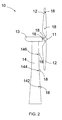
FIG. 2 is a side view of the wind turbine ofFIG. 1 . -
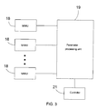
FIG. 3 is a block diagram of a parameter processing device according to an embodiment. -
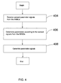
FIG. 4 is a flowchart of a method for determining parameters of a wind turbine according to one embodiment. -
FIG. 5 is a schematic view of a wind turbine according to another embodiment. - Various embodiments of the invention relate to a wind turbine including multiple Micro Inertial Measurement Units (MIMUs) mounted at various locations of the wind turbine to monitor the status of the wind turbine. For example, MIMUs mounted on each of the blades of the wind turbine sense parameter signals of the blades, and supply these signals to a parameter processing unit. The parameter processing unit determines parameters of the blades according to the sensed parameter signals.
- Unless defined otherwise, technical and scientific terms used herein have the same meaning as is commonly understood by one of ordinary skill in the art to which this invention belongs. The terms "first", "second", and the like, as used herein do not denote any order, quantity, or importance, but rather are used to distinguish one element from another. Also, the terms "a" and "an" do not denote a limitation of quantity, but rather denote the presence of at least one of the referenced items, and terms such as "front", "back", "bottom", and/or "top", unless otherwise noted, are merely used for convenience of description, and are not limited to any one position or spatial orientation. Moreover, the terms "coupled" and "connected" are not intended to distinguish between a direct or indirect coupling/connection between two components. Rather, such components may be directly or indirectly coupled/connected unless otherwise indicated.
- Referring to
FIGs. 1 and2 , awind turbine 10 according to one embodiment includes threeblades 12, atower 14, and amain shaft 16. Thewind turbine 10 may also include ahub 11, anacelle 13, a generator (not shown), and so on, which are conventional technology and, thus, not described here. In other embodiments, the number of theblades 12 may be two or more than three. - In the illustrated embodiment of
FIGs. 1 and2 , eachblade 12 includes two Micro Inertial Measurement Units (MIMUs) 18 respectively mounted on aroot point 122 and atip point 124 of thecorresponding blade 12. Thetower 14 comprises threeMIMUs 18 respectively mounted on abase point 142, amiddle point 144, and atop point 146 of thetower 14. Themain shaft 16 comprises anMIMU 18 mounted thereon. - In the illustrated embodiment of
FIG. 1 , theMIMUs 18 are mounted on external walls of theblades 12, thetower 14, and themain shaft 16. In other embodiments, theMIMUs 18 can be mounted on inner walls of theblades 12, thetower 14, and themain shaft 16, or theMIMUs 18 can be embedded in the walls thereof according to requirements. In other embodiments, the number and the mounted position of theMIMUs 18 can be adjusted according to requirements of desired application or for desired results. For example, eachblade 12 can include three ormore MIMUs 18 mounted at different positions of thecorresponding blades 12. In other embodiments, other parts of thewind turbine 10, such as thehub 11 and thenacelle 13 also includeMIMUs 18 to provide parameter signals as necessary. - Referring to
FIG. 3 , thewind turbine 10 further includes aparameter processing unit 19 coupled to all of theMIMUs 18. Theparameter process unit 19 may be arranged in thetower 14, thenacelle 13, or in another location according to requirements. The communication mode between theparameter processing unit 19 and theMIMUs 18 can be wireless communication mode or cable communication mode. For example, theMIMUs 18 may be respectively coupled to first wireless transceivers, and theparameter processing unit 19 may be coupled to a second wireless transceiver, thus theMIMUs 18 can communicate with theparameter processing 19 through the first and second wireless transceivers. In one embodiment, theparameter processing unit 19 may be a computer system or a microprocessor system, for example. Theparameter processing unit 19 is also coupled to acontroller 21 used to receive the parameter signals from theparameter processing unit 19 and control thewind turbine 10 accordingly. In other embodiments, theparameter processing unit 19 and thecontroller 21 can be integrated as necessary. - The
MIMUs 18 are used to sense parameter signals of the corresponding mounted position of thewind turbine 10. The MIMU is a comprehensive motion capture sensing apparatus, which can sense three dimensional (3D) orientation (pitch, roll, yaw) signals, as well as 3D acceleration signals, 3D rate of turn signals, 3D magnetic field signals, and other related parameter signals in real time according to different kinds of MIMUs. In certain embodiments, the MIMU 18 may include a 3D accelerometer, a 3D gyroscope, and a 3D magnetometer at the same time, or include two kinds of them, or include one kind of them. Theparameter processing unit 19 receives the sensed parameter signals from all of theMIMUs 18 and determines parameters of thewind turbine 10 by implementing an embedded model-based estimation program therein. - According to an embodiment, the determined parameters can include blade pitch, blade rotating speed, structural vibration, blade bending moment, blade twisting moment, tip displacement, three dimensional motion track, tower bending moment, yaw, rotor speed, generator speed, torque, thrust, and load. Each
MIMU 18 can sense different types of parameter signals, such as 3D rate of turn signals (Wx, Wy, Wz), 3D acceleration signals (ax, ay, az), 3D earth magnetic field signals (mx, my, mz), and 3D orientation signals (θ, γ, ψ), for example. - In detail, during the determining process, the above sensed parameter signals together with a coordinate parameter (xn, yn, zn) of the
corresponding MIMU 18 are processed into a vector Tn, where "n" stands for the number ofMIMU 18. For example, "n" may be 1, 2, 3..., etc. The vector Tn can be noted as the following equation:
- Furthermore, the sensed signals from all of the
MIMUs 18 can be noted as a matrix S, whose row and column are equal to N and 15 respectively. Wherein, "N" stands for the total number ofMIMUs 18, for example N=10. The matrix S can be noted as the following equation: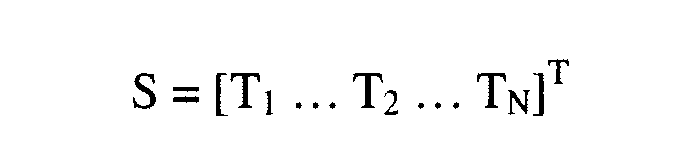
- There is also a matrix So to denote the initial data of all parameter signals. The matrix So can be determined by processing the data into the matrix S when the
wind turbine 10 is in a static status. Subsequently, the real time data in the matrix S and the initial data in the matrix So will be used to determine the mentioned parameters. In other embodiments, the parameters also can be determined by other algorithm processed by theparameter processing unit 19. -
FIG. 4 is a flowchart of one embodiment of a process for determining parameters of thewind turbine 10. Instep 404, the sensed parameter signals from theMIMUs 18 are received, for example by theparameter processing unit 19. Theparameter processing unit 19 determines the parameters according to the sensed signals from theMIMUs 18 instep 406. Instep 408, theparameter processing unit 19 generates parameter signals based on the sensed signals. The parameter signals are monitored by thecontrol unit 21 to control thewind turbine 10 accordingly. - In
FIGs. 1 and2 , the illustratedwind turbine 10 is a horizontal axistype wind turbine 10. However, embodiments of the invention can also be utilized in any other type of wind turbines. For example,FIG. 5 illustrates another type (vertical axis type) ofwind turbine 20. Thewind turbine 20 in this embodiment includes eleven MIMUs 18 mounted on different parts of thewind turbine 20. For example, eachblade 22 includes two MIMUs 18, thetower 24 includes threeMIMUs 18, and themain shaft 26 includes twoMIMUs 18. The difference between thewind turbine 10 and thewind turbine 20 is the number and the mounted position of theMIMUs 18, which is decided by the type, size, or other characteristics of thewind turbines - In the embodiments disclosed herein,
MIMUs 18 are utilized to monitor different parameters of different parts of thewind turbines - While the invention has been described with reference to exemplary embodiments, it will be understood by those skilled in the art that various changes may be made and equivalents may be substituted for elements thereof without departing from the scope of the invention. In addition, many modifications may be made to adapt a particular situation or material to the teachings of the invention without departing from the essential scope thereof. Therefore, it is intended that the invention not be limited to the particular embodiment disclosed as the best mode contemplated for carrying out this invention, but that the invention will include all embodiments falling within the scope of the appended claims.
- Various aspects and embodiments of the present invention are defined by the following numbered clauses:
- 1. A wind turbine, comprising:
- a plurality of blades;
- a plurality of Micro Inertial Measurement Units (MIMUs) mounted on each of the plurality of blades and sensing parameter signals of the plurality of blades; and
- a parameter processing unit receiving the parameter signals from the MIMUs and determining parameters of the plurality of blades according to the received parameter signals.
- 2. The wind turbine of clause 1, wherein two MIMUs are respectively mounted on a root point and a tip point of the corresponding blade.
- 3. The wind turbine of any preceding clause, wherein the parameters determined by the parameter processing unit comprises at least one of blade pitch, blade rotating speed, structural vibration, blade bending moment, blade twisting moment, tip displacement, and three dimensional motion track.
- 4. The wind turbine of any preceding clause, further comprising:
- a tower; and
- a plurality of MIMUs mounted on the tower and sensing parameter signals of the tower;
- wherein the parameter processing unit further receives sensed parameter signals from the plurality of MIMUs mounted on the tower and determines parameters of the tower according to the received parameter signals from the plurality of MIMUs mounted on the tower.
- 5. The wind turbine of any preceding clause, wherein three MIMUs are respectively mounted on a base point, a middle point, and a top point of the tower.
- 6. The wind turbine of any preceding clause, wherein the parameters determined by the parameter processing unit comprises at least one of blade pitch, blade rotating speed, structural vibration, blade bending moment, blade twisting moment, tip displacement, three dimensional motion track, and tower bending moment.
- 7. The wind turbine of any preceding clause, further comprising:
- a rotor comprising a shaft; and
- a MIMU mounted on the shaft and sensing parameter signals of the shaft;
- wherein the parameter processing unit further receives sensed parameter signals from the MIMU mounted on the shaft and determines parameters of the shaft according to the received parameter signals from the MIMU mounted on the shaft.
- 8. The wind turbine of any preceding clause, wherein the parameters determined by the parameter processing unit comprises at least one of blade pitch, blade rotating speed, structural vibration, blade bending moment, blade twisting moment, tip displacement, three dimensional motion track, tower bending moment, yaw, rotor speed, generator speed, torque, thrust, and load.
- 9. The wind turbine of any preceding clause, further comprising:
- a rotor comprising a shaft; and
- a MIMU mounted on the shaft and sensing parameter signals of the shaft;
- wherein the parameter processing unit further receives sensed parameter signals from the MIMU mounted on the shaft and determines parameters of the shaft according to the received parameter signals from the MIMU mounted on the shaft.
- 10. The wind turbine of any preceding clause, wherein the parameters determined by the parameter processing unit comprises at least one of blade pitch, blade rotating speed, structural vibration, blade bending moment, blade twisting moment, tip displacement, three dimensional motion track, yaw, rotor speed, generator speed, torque, and thrust.
- 11. A method for determining parameters of a wind turbine, comprising:
- receiving sensed signals from Micro Inertial Measurement Units (MIMUs) mounted on each blade of the wind turbine; and
- determining parameters according to the sensed signals from the MIMUs.
- 12. The method of any preceding clause, wherein receiving sensed signals comprises receiving sensed signals from two MIMUs respectively mounted on a root point and a tip point of the corresponding blade.
- 13. The method of any preceding clause, wherein determining parameters according to the sensed signals from the MIMUs comprises determining at least one of blade pitch, blade rotating speed, structural vibration, blade bending moment, blade twisting moment, tip displacement, and three dimensional motion track.
- 14. The method of any preceding clause, further comprising:
- receiving sensed signals from a plurality of MIMUs mounted on a tower of the wind turbine; and
- determining parameters according to the sensed signals from the plurality of MIMU mounted on the tower.
- 15. The method of any preceding clause, wherein receiving sensed signals comprises receiving sensed signals from three MIMUs respectively mounted on a base point, a middle point, and a top point of the tower.
- 16. The method of any preceding clause, wherein determining parameters according to the sensed signals from the plurality of MIMUs mounted on the tower comprises determining at least one of blade pitch, blade rotating speed, structural vibration, blade bending moment, blade twisting moment, tip displacement, three dimensional motion track, and tower bending moment.
- 17. The method of any preceding clause, further comprising:
- receiving sensed signals from an MIMU mounted on a shaft of the wind turbine; and
- determining parameters according to the sensed signals from the MIMU mounted on the shaft.
- 18. The method of any preceding clause, wherein determining parameters according to the sensed signals from the MIMU mounted on the shaft comprises determining at least one of blade pitch, blade rotating speed, structural vibration, blade bending moment, blade twisting moment, tip displacement, three dimensional motion track, tower bending moment, yaw, rotor speed, generator speed, torque, thrust, and load.
- 19. The method of any preceding clause, further comprising:
- receiving sensed signals from a MIMU mounted on a shaft of a rotor of the wind turbine; and
- determining parameters according to the sensed signals from the MIMU mounted on the shaft.
- 20. The method of any preceding clause, wherein determining parameters according to the sensed signals from the MIMU mounted on the shaft comprises determining at least one of blade pitch, blade rotating speed, structural vibration, blade bending moment, blade twisting moment, tip displacement, three dimensional motion track, yaw, rotor speed, generator speed, torque, and thrust.
Claims (15)
- A wind turbine (10), comprising:a plurality of blades (12);a plurality of Micro Inertial Measurement Units (MIMUs) (18) mounted on each of the plurality of blades and sensing parameter signals of the plurality of blades; anda parameter processing unit (19) receiving the parameter signals from the MIMUs (18) and determining parameters of the plurality of blades according to the received parameter signals.
- The wind turbine (10) of claim 1, wherein two MIMUs (18) are respectively mounted on a root point and a tip point of the corresponding blade (12).
- The wind turbine (10) of any preceding claim, wherein the parameters determined by the parameter processing unit (19) comprises at least one of blade pitch, blade rotating speed, structural vibration, blade bending moment, blade twisting moment, tip displacement, and three dimensional motion track.
- The wind turbine (10) of any preceding claim, further comprising:a tower (14); anda plurality of MIMUs (18) mounted on the tower (14) and sensing parameter signals of the tower;wherein the parameter processing unit (19) further receives sensed parameter signals from the plurality of MIMUs mounted on the tower and determines parameters of the tower according to the received parameter signals from the plurality of MIMUs mounted on the tower.
- The wind turbine (10) of claim 4, wherein three MIMUs (18) are respectively mounted on a base point, a middle point, and a top point of the tower (14).
- The wind turbine (10) of any preceding claim, wherein the parameters determined by the parameter processing unit (19) comprises at least one of blade pitch, blade rotating speed, structural vibration, blade bending moment, blade twisting moment, tip displacement, three dimensional motion track, and tower bending moment.
- The wind turbine (10) of any preceding claim, further comprising:a rotor (11) comprising a shaft; anda MIMU (18) mounted on the shaft and sensing parameter signals of the shaft;wherein the parameter processing unit (19) further receives sensed parameter signals from the MIMU mounted on the shaft and determines parameters of the shaft according to the received parameter signals from the MIMU mounted on the shaft.
- The wind turbine (10) of any preceding claim, wherein the parameters determined by the parameter processing unit (19) comprises at least one of blade pitch, blade rotating speed, structural vibration, blade bending moment, blade twisting moment, tip displacement, three dimensional motion track, tower bending moment, yaw, rotor speed, generator speed, torque, thrust, and load.
- The wind turbine (10) of any preceding claim, further comprising:a rotor (12) comprising a shaft; anda MIMU (18) mounted on the shaft and sensing parameter signals of the shaft;wherein the parameter processing unit (19) further receives sensed parameter signals from the MIMU mounted on the shaft and determines parameters of the shaft according to the received parameter signals from the MIMU mounted on the shaft.
- The wind turbine (10) of any preceding claim, wherein the parameters determined by the parameter processing unit (19) comprises at least one of blade pitch, blade rotating speed, structural vibration, blade bending moment, blade twisting moment, tip displacement, three dimensional motion track, yaw, rotor speed, generator speed, torque, and thrust.
- A method for determining parameters of a wind turbine (10), comprising:receiving sensed signals from Micro Inertial Measurement Units (MIMUs) (18) mounted on each blade (12) of the wind turbine (10); anddetermining parameters according to the sensed signals from the MIMUs.
- The method of claim 11, wherein receiving sensed signals comprises receiving sensed signals from two MIMUs (18) respectively mounted on a root point and a tip point of the corresponding blade (12).
- The method of claim 11 or claim 12, wherein determining parameters according to the sensed signals from the MIMUs (18) comprises determining at least one of blade pitch, blade rotating speed, structural vibration, blade bending moment, blade twisting moment, tip displacement, and three dimensional motion track.
- The method of any of claims 11 to 13, further comprising:receiving sensed signals from a plurality of MIMUs (18) mounted on a tower (14) of the wind turbine (10); anddetermining parameters according to the sensed signals from the plurality of MIMUs (18) mounted on the tower (14).
- The method of claim 14, wherein receiving sensed signals comprises receiving sensed signals from three MIMUs (18) respectively mounted on a base point, a middle point, and a top point of the tower (14).
Applications Claiming Priority (1)
| Application Number | Priority Date | Filing Date | Title |
|---|---|---|---|
| CN2011101411981A CN102797634A (en) | 2011-05-27 | 2011-05-27 | Wind turbine and method for monitoring parameter thereof |
Publications (2)
| Publication Number | Publication Date |
|---|---|
| EP2527651A2 true EP2527651A2 (en) | 2012-11-28 |
| EP2527651A3 EP2527651A3 (en) | 2017-04-26 |
Family
ID=46148724
Family Applications (1)
| Application Number | Title | Priority Date | Filing Date |
|---|---|---|---|
| EP12169611.6A Withdrawn EP2527651A3 (en) | 2011-05-27 | 2012-05-25 | Wind Turbine and Method for Determining Parameters of Wind Turbine |
Country Status (3)
| Country | Link |
|---|---|
| US (1) | US20120303277A1 (en) |
| EP (1) | EP2527651A3 (en) |
| CN (1) | CN102797634A (en) |
Cited By (1)
| Publication number | Priority date | Publication date | Assignee | Title |
|---|---|---|---|---|
| EP3816434A1 (en) * | 2019-10-28 | 2021-05-05 | Siemens Gamesa Renewable Energy A/S | Blade vibration suppression system for a wind turbine and associated method |
Families Citing this family (16)
| Publication number | Priority date | Publication date | Assignee | Title |
|---|---|---|---|---|
| US20130003071A1 (en) * | 2011-06-30 | 2013-01-03 | Catch the Wind, Inc. | System and Method of In Situ Wind Turbine Blade Monitoring |
| WO2013110215A1 (en) * | 2012-01-27 | 2013-08-01 | General Electric Company | Wind turbine and method for determining parameters of wind turbine |
| EP2690286A1 (en) * | 2012-07-23 | 2014-01-29 | Siemens Aktiengesellschaft | Monitoring arrangement |
| DE102013014622A1 (en) * | 2013-09-02 | 2015-03-05 | Northrop Grumman Litef Gmbh | System and method for determining movements and vibrations of moving structures |
| CN104454350B (en) * | 2013-09-23 | 2019-01-08 | 通用电气公司 | Wind turbine and its control method for reducing rotor unbalance load |
| CN104595112B (en) | 2013-10-30 | 2018-01-16 | 通用电气公司 | Wind turbine and the method for assessing its blade health status |
| DE102013227055A1 (en) * | 2013-12-23 | 2015-06-25 | Robert Bosch Gmbh | Method for determining a rotational angle position and / or a rotational speed |
| CN105089931A (en) | 2014-05-13 | 2015-11-25 | 通用电气公司 | Draught fan and alignment method for draught fan blades |
| ES2780689T3 (en) * | 2014-10-01 | 2020-08-26 | Ge Renewable Tech | Rotating machine and installation for converting energy comprising such machine |
| CN104989594A (en) * | 2015-06-20 | 2015-10-21 | 上海电机学院 | Wind generating set vibration waveform collection system and method |
| US10247170B2 (en) * | 2016-06-07 | 2019-04-02 | General Electric Company | System and method for controlling a dynamic system |
| US10539116B2 (en) | 2016-07-13 | 2020-01-21 | General Electric Company | Systems and methods to correct induction for LIDAR-assisted wind turbine control |
| DE102016215533A1 (en) * | 2016-08-18 | 2018-02-22 | Wobben Properties Gmbh | Measuring arrangement of a wind turbine |
| EP4038276B1 (en) | 2019-10-03 | 2024-05-29 | Syddansk Universitet | A method and a system for tracking motion of a blade |
| AT523919B1 (en) * | 2020-08-14 | 2022-01-15 | Eologix Sensor Tech Gmbh | Measuring device for wind turbines |
| EP3961177B1 (en) * | 2020-08-25 | 2022-06-15 | AIRBUS HELICOPTERS DEUTSCHLAND GmbH | A measurement apparatus for determining a bending moment |
Family Cites Families (11)
| Publication number | Priority date | Publication date | Assignee | Title |
|---|---|---|---|---|
| US7822560B2 (en) * | 2004-12-23 | 2010-10-26 | General Electric Company | Methods and apparatuses for wind turbine fatigue load measurement and assessment |
| DE102005031436B4 (en) * | 2005-07-04 | 2012-06-28 | Johannes Reetz | Method for monitoring an elasto-mechanical support structure |
| US7417332B2 (en) * | 2006-08-24 | 2008-08-26 | General Electric Company | Method and apparatus of monitoring a machine |
| CN100462683C (en) * | 2007-02-07 | 2009-02-18 | 北京航空航天大学 | A Miniature Inertial Measurement Unit with Implicit Structure |
| CN101545828A (en) * | 2008-03-10 | 2009-09-30 | 通用电气公司 | Independent sensing system for a winding turbine |
| US20090232635A1 (en) * | 2008-03-12 | 2009-09-17 | General Electric Company | Independent sensing system for wind turbines |
| CA2724311A1 (en) * | 2008-05-13 | 2009-11-19 | Purdue Research Foundation | Monitoring of wind turbines |
| US8004101B2 (en) * | 2008-10-11 | 2011-08-23 | Michael Scott Aaron | Vertical axis variable geometry wind energy collection system |
| WO2010046403A2 (en) * | 2008-10-23 | 2010-04-29 | Vestas Wind Systems A/S | A wind turbine and a method for monitoring a wind turbine |
| US20100140936A1 (en) * | 2008-12-23 | 2010-06-10 | General Electric Company | Wind turbine with gps load control |
| US20110158806A1 (en) * | 2009-04-15 | 2011-06-30 | Arms Steven W | Wind Turbines and Other Rotating Structures with Instrumented Load-Sensor Bolts or Instrumented Load-Sensor Blades |
-
2011
- 2011-05-27 CN CN2011101411981A patent/CN102797634A/en active Pending
-
2012
- 2012-05-25 EP EP12169611.6A patent/EP2527651A3/en not_active Withdrawn
- 2012-05-25 US US13/480,963 patent/US20120303277A1/en not_active Abandoned
Non-Patent Citations (1)
| Title |
|---|
| None |
Cited By (2)
| Publication number | Priority date | Publication date | Assignee | Title |
|---|---|---|---|---|
| EP3816434A1 (en) * | 2019-10-28 | 2021-05-05 | Siemens Gamesa Renewable Energy A/S | Blade vibration suppression system for a wind turbine and associated method |
| US11460002B2 (en) | 2019-10-28 | 2022-10-04 | Siemens Gamesa Renewable Energy A/S | Blade vibration suppression system for a wind turbine and associated method |
Also Published As
| Publication number | Publication date |
|---|---|
| CN102797634A (en) | 2012-11-28 |
| US20120303277A1 (en) | 2012-11-29 |
| EP2527651A3 (en) | 2017-04-26 |
Similar Documents
| Publication | Publication Date | Title |
|---|---|---|
| EP2527651A2 (en) | Wind Turbine and Method for Determining Parameters of Wind Turbine | |
| EP2693049B1 (en) | Control system and method for mitigating rotor imbalance on a wind turbine | |
| US20150118047A1 (en) | Wind turbine and method for determining parameters of wind turbine | |
| US10018177B2 (en) | Control system and method for mitigating rotor imbalance on a wind turbine | |
| JP6906354B2 (en) | Wind turbine generator fatigue damage calculation device, wind power generation system, and wind turbine generator fatigue damage calculation method | |
| EP2466131B1 (en) | Systems and methods for monitoring a condition of a rotor blade for a wind turbine | |
| EP2169218B1 (en) | System and method for estimating wind condition for wind turbines | |
| US9606518B2 (en) | Control system and method of predicting wind turbine power generation | |
| EP2469083B1 (en) | Offshore wind turbine and method of operating same | |
| EP2743500B1 (en) | System for managing a fatigue life distribution, method of operating a plurality of wind turbines | |
| EP2258946A2 (en) | Load identification system for a wind turbine | |
| US20110142620A1 (en) | Apparatus and method for operation of a wind turbine | |
| EP2778395A2 (en) | System and method for reducing loads acting on a wind turbine in response to transient wind conditions by means of pitch control | |
| EP3511567B1 (en) | State monitoring device, system and method for wind power generating device | |
| JP2017090145A (en) | Windmill blade deformation measuring device and windmill blade deformation evaluation system | |
| US20130103327A1 (en) | Fault detection device for wind power generator and means of judgment thereof | |
| EP4330692B1 (en) | Determining wind turbine rotor speed | |
| KR20130028923A (en) | Control device for a wind power plant | |
| EP4179201B1 (en) | Determining sunlight effect on wind turbine tower inclination using tower top accelerometers | |
| CN103711642B (en) | For determining the system and method for wind turbine operational factor | |
| EP4088020B1 (en) | Wind turbine oscillation detection | |
| EP4224011A1 (en) | Method and device of controlling a wind turbine by individual pitch control | |
| EP4185770B1 (en) | Imbalance estimation for the wind rotor of a wind turbine | |
| Loss et al. | Using MEMS acceleration sensors for monitoring blade tip movement of wind turbines | |
| EP4339453A1 (en) | Method for operating a wind turbine, control system and wind turbine |
Legal Events
| Date | Code | Title | Description |
|---|---|---|---|
| PUAI | Public reference made under article 153(3) epc to a published international application that has entered the european phase |
Free format text: ORIGINAL CODE: 0009012 |
|
| AK | Designated contracting states |
Kind code of ref document: A2 Designated state(s): AL AT BE BG CH CY CZ DE DK EE ES FI FR GB GR HR HU IE IS IT LI LT LU LV MC MK MT NL NO PL PT RO RS SE SI SK SM TR |
|
| AX | Request for extension of the european patent |
Extension state: BA ME |
|
| PUAL | Search report despatched |
Free format text: ORIGINAL CODE: 0009013 |
|
| AK | Designated contracting states |
Kind code of ref document: A3 Designated state(s): AL AT BE BG CH CY CZ DE DK EE ES FI FR GB GR HR HU IE IS IT LI LT LU LV MC MK MT NL NO PL PT RO RS SE SI SK SM TR |
|
| AX | Request for extension of the european patent |
Extension state: BA ME |
|
| RIC1 | Information provided on ipc code assigned before grant |
Ipc: F03D 11/00 00000000AFI20170320BHEP |
|
| STAA | Information on the status of an ep patent application or granted ep patent |
Free format text: STATUS: THE APPLICATION IS DEEMED TO BE WITHDRAWN |
|
| 18D | Application deemed to be withdrawn |
Effective date: 20171021 |